Article

Four Channel 6.5 kV, 65 A, 100 ns–100 µs Generator with Advanced Control of Pulse and Burst Protocols for Biomedical and Biotechnological Applications

by
Aleh Kandratsyeu
1,
Uladzimir Sabaleuski
2,
Luis Redondo
3,* and
Andrei G. Pakhomov
4
1
EnergyPulse Systems, 1600-546 Lisbon, Portugal
2
OEM Tech, Odoevskogo 129, 220018 Minsk, Belarus
3
Pulsed Power Advanced Applications Group, Lisbon Engineering Superior Institute, GIAAPP/ISEL, 1959-007 Lisbon, Portugal
4
Frank Reidy Research Center for Bioelectrics, Old Dominion University, Norfolk, VA 23529, USA
*
Author to whom correspondence should be addressed.
Appl. Sci. 2021, 11(24), 11782; https://doi.org/10.3390/app112411782
Submission received: 30 October 2021 / Revised: 2 December 2021 / Accepted: 9 December 2021 / Published: 11 December 2021
(This article belongs to the Special Issue Biomedical Applications of Pulsed Power and Plasmas)

Abstract

:

Featured Application

Pulsed generator for biomedical and biotechnology applications.

Abstract

Pulsed electric fields in the sub-microsecond range are being increasingly used in biomedical and biotechnology applications, where the demand for high-voltage and high-frequency pulse generators with enhanced performance and pulse flexibility is pushing the limits of pulse power solid state technology. In the scope of this article, a new pulsed generator, which includes four independent MOSFET based Marx modulators, operating individually or combined, controlled from a computer user interface, is described. The generator is capable of applying different pulse shapes, from unipolar to bipolar pulses into biological loads, in symmetric and asymmetric modes, with voltages up to 6.5 kV and currents up to 65 A, in pulse widths from 100 ns to 100 µs, including short-circuit protection, current and voltage monitoring. This new scientific tool can open new research possibility due to the flexibility it provides in pulse generation, particularly in adjusting pulse width, polarity, and amplitude from pulse-to-pulse. It also permits operating in burst mode up to 5 MHz in four independent channels, for example in the application of synchronized asymmetric bipolar pulses, which is shown together with other characteristics of the generator.

1. Introduction

Currently, there is a growing demand for high-voltage pulse generators, with pulses between 1 and 10 kV, with 10 s A, able to deliver high-frequency pulse bursts, in the MHz range. The generators should have high flexibility in order to apply pulses from 100 s ns to 100 s µs, with capability to adjust the pulse width, polarity and amplitude from pulse-to-pulse. These different pulse shapes, including unipolar and bipolar pulses, are currently the key to the huge evolution in the application of pulsed electric fields to biological tissues for electropermeabilization of cells, in biomedical and biotechnological contexts [1].
The application of high-voltage pulses, in the range of 100 s ns to 100 s µs, is very important within electroporation-based therapies and technologies in medicine and biotechnology, for example in gene electrotransfer, tissue ablation, extraction of compounds, or electrochemotherapy [2,3,4]. These pulses can be applied with different shapes; for example, symmetric unipolar pulses were reported [5] for biophysical tumor treatment and [6] for platelet activation and asymmetric unipolar pulses was reported [7] for tissues ablation and [8] for electroporation of mammal cells. In addition, high-frequency burst of symmetric bipolar microsecond range high-voltage pulses have been recently reported [9] to minimize the effect of muscle contractions during irreversible electroporation, Ref. [8] for electroporation of mammal cells, Ref. [10] for inducing irreversible electroporation in brain tumors and in [11] for inhibition of tumor growth. In addition, the use of bipolar asymmetric pulses was reported [12] for in vivo experimental treating of subcutaneous tumors in mice to evaluate tumor responses [13], for altering membrane permeability parameters in relation to unipolar pulse application [14], for irreversible electroporation in cardiac ablation and by [15], and for decreasing irreversible electroporation thresholds in primary and metastatic brain cancers. Finally, the application of synchronized bipolar pulses has been reported [16] to minimize neuromuscular stimulation in ablation therapies [17] for uniform tumor ablation and stimulation targeting away from electrodes, and [18] to minimize stimulation near pulse delivering electrodes in electrical stimulation. Many of these applications share the decisive advantage that the pulse width, amplitude, and polarity can be changed from pulse-to-pulse operation.
While there are several techniques to generate high-voltage pulses, being the direct capacitive discharge [19], the use of transformer [20], pulse forming lines [21], and inductive energy storage [22] methods some of them. The requirement for 100 s ns to 100 s µs pulse variation narrows the selection to direct capacitive discharge [1]. Considering this technique and the electroporation applications in biomedical and biotechnological contexts, several authors have reported the use of semiconductor-based Marx generators, for positive and bipolar operation [8,23,24]. In addition, the use of a single capacitors bank with semiconductor stack has been reported [5]. Alternatively, H-bridge circuits have been used for bipolar generation individually and stacked in order to get a high amplitude voltage [5,12,15]. Similarly, multilevel-type generators can be used to produce bipolar pulses [15,25].
It is worth noting that in most of the reports describing the pulse generators above, there are many details about the circuit’s specifications. However, often the circuit protections are not examined, namely the overcurrent protection which is very important for circuit operation.
Common to all the circuits presented is the fact that only semiconductor switches can be used, as MHz on–off capability is needed. Hence, the present demand for pulse generator technology has been driven by the evolution of solid state pulse generators, with optimized performance and reliability [26]. This has been pushed by the development of more efficient semiconductor switches, being the MOSFETs, i.e., metal oxide semiconductor field effect transistors, based on SiC technology, presently the most used switches.
The aim of this paper was to present a highly flexible pulse generator that can be used in several electroporation applications in biomedical and biotechnological context described, where the generation of high-voltage, high-frequency pulse burst of different pulse shapes, with pulse-to-pulse adjustment of pulse width, polarity, and amplitude is possible.
Henceforward, a new pulsed generator, which includes four independent MOSFET based Marx modulators, operating individually and in combination, controlled from a computer user interface is described. The generator can be programmed to apply into biological loads different pulse shapes, from unipolar to bipolar pulses, in symmetric and asymmetric modes, with voltages up to 6.5 kV and currents up to 65 A, in pulse width from 100 ns to 100 µs, including overcurrent protection, current, and voltage monitoring.
The design of this generator gives it the flexibility to generate pulses with different pulse widths, polarity, and amplitude from pulse-to-pulse, while operating in burst mode up to 5 MHz on four independent channels for applying synchronized asymmetric bipolar pulses. This paper shows these properties and other characteristics of the generator.

2. Four Channels Generator

The basic structure of the four channels generator is presented in Figure 1, where four main blocks are identified: (1) the four positive Marx modulators, MM, also, identified as output channels, respectively, 0, 1, 2 and 3, each one operating independently; (2) capacitor charging power supply, CCPS, common to all channels, with voltage set by the PC user interface, Udc; (3) main control board and trigger signals generator board, which receive the command lines from the PC user interface, programs all the four Marx modulators and sends the trigger signals to all the MM; (4) PC user interface, from where the user sets which channels produce pulses, the pulse sequence for each channel, and the amplitude voltage for each pulse in the sequence. The start pulses command can be internal or external, from an external trigger signal.
The pulse generator operates in burst mode for each channel, with the possibility to repeat the burst sequence, from 2 to continuous operation, at a desirable frequency.
At the output of each channel, voltage, and current monitoring are available, respectively, from a voltage divider with 200 gain and from a current transformer with 50 gain. These are helpful for diagnostic, depending on user applications.

2.1. Solid State Marx Modulator

The simplified topology, of each positive Marx modulator, MM, with 8 stages, capable of delivering repetitive positive high voltage output pulses to a load, between HV+ and HV−, using MOSFETs as on–off switches, is presented in Figure 2, where each stage comprises a diode Di, a capacitor Ci, and two switches, Sci and Spi.
The basic circuit operation, of Figure 2 circuit, can be understood considering two main operating modes. First the charging mode of the main capacitors Ci, for i ∈ [1–8], from the capacitor charging power supply, CCPS, Udc, connected to terminals PS+ and PS−, where Sci and Spi switches are, respectively, on and off. In this operating mode, the HV+ terminal is grounded, resetting the load. Then, the positive pulse mode, where switches Sci and Spi are, respectively, off and on, if applying full voltage, approximately, Vout ≈ 8Udc into a load, connected to terminals HV+ and HV−. A more detailed description of the operation of the circuit is Figure 2 is given [27].
It is possible to apply a lower voltage into the load, also, different from 8Udc, by choosing the number of Spi switches to set on. For example, if Sp1 is not set on, during pulse mode, the load current flows through the Sc1 anti-parallel diode and bypass stage one, then the output voltage is 7Udc in this situation.
Considering the operating modes described, one can produce at the output a sequence of pulses with different amplitudes, up to 8, and various pulse widths, depending on the time Spi switches are set on. Clearly, in order to do so, each stage much be triggered independently, which increases the control circuits complexity. The control circuit is described in the next sections.

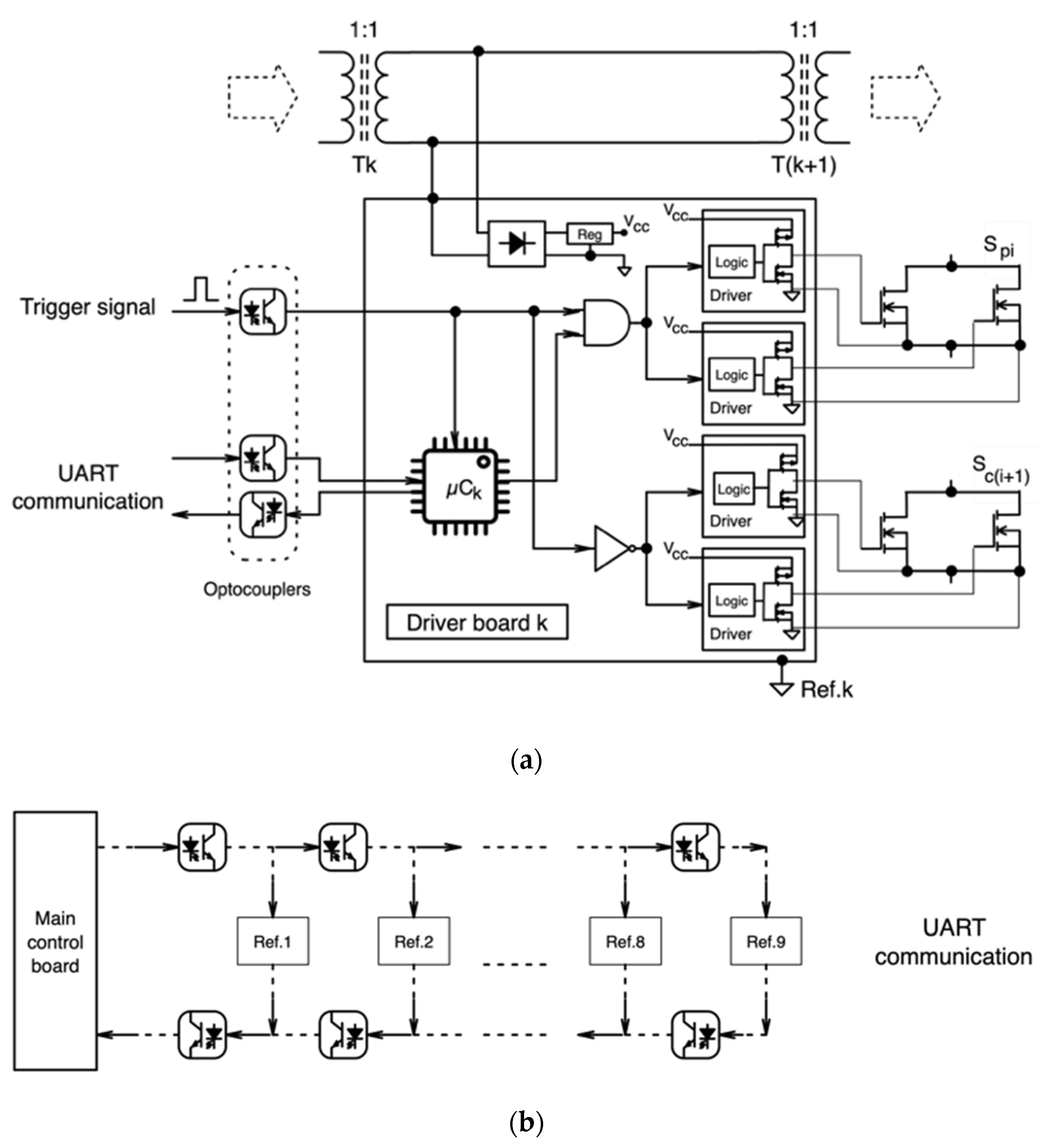
2.2. Marx Modulator Trigger Circuit

From the circuit topology of Figure 2, one can identify 9 voltage reference nodes, from Ref.1 to Ref.9, which can be used to place the switches driver boards. Hence, to supply energy to all the switch driver boards, with galvanic insulation, a series of toroid transformers was implemented, which is feed be a 150 kHz inverter, as shown in Figure 3.
As shown in Figure 3, only one switch is placed on Ref.1 and Ref.9, but two switches are placed between Ref.2 and Ref.8, a charge switch from one stage, i, and a pulse switch from a previous stage, i − 1, as seen in Figure 2.
In a more detailed schematic, Figure 4a shows a generic switch driver board k placed at voltage reference k, being k ∈ [1–9], as seen in Figure 3. Each switch driver board is capable of triggering two switches, Spi and Sci, where each one comprises two MOSFETs in parallel, both triggered by an individual driver to increase switching speed, as seen in Figure 4a.
Considering Figure 4a, all the components in each board are placed on the same voltage reference, being floating in relation to safety ground. During pulse mode, each voltage reference k jumps to the resulting sum of the voltage on each capacitor in the series. Then, the trigger signals to each driver board, must be sent via galvanic isolation.
In each Marx modulator the trigger signal, generated on the main control board, is sent to the driver boards by associations of optocouplers, as seen in Figure 4b,c. The use of optocouplers was chosen in alternative to optic-fibers for compactness and to reduce the propagation delay times, normally, found on optic-fibers receivers and transmitters. Figure 4b shows the opto-coupler association for the UART communication and Figure 4c the transmission of the trigger signal to each MM reference driver position, where additional delay modules, D, comprising an RC network and gate door, are used, to compensate for the propagation delays in the opto-couplers.
From Figure 4, it can be seen that when the trigger signal is zero, the charging switches are set on, but when the trigger pulse is high, all charging switches are set off (i.e., there is a NOT logic gate). In relation to the pulse switches, when the trigger signal is zero, the pulse switches are set off, but when the trigger signal is high, the pulse switches state depends on the programming loaded on the µCk, in each driver board k (i.e., there is an AND logic gate, with the trigger signal and a signal from the board µCk). The µCk programming is made by the main board, prior to the trigger signal generation, in order to set which Marx stage contributes to the final pulse, enabling the generation of pulses with different amplitudes in the same pulse sequence, or burst. This is called setting the Mask.
The µCk programming in each Marx modulator is made via UART (i.e., universal asynchronous receiver/transmitter) communication protocol, from main control board, where the two lines use optocoupler strings for insulation from the high voltage.

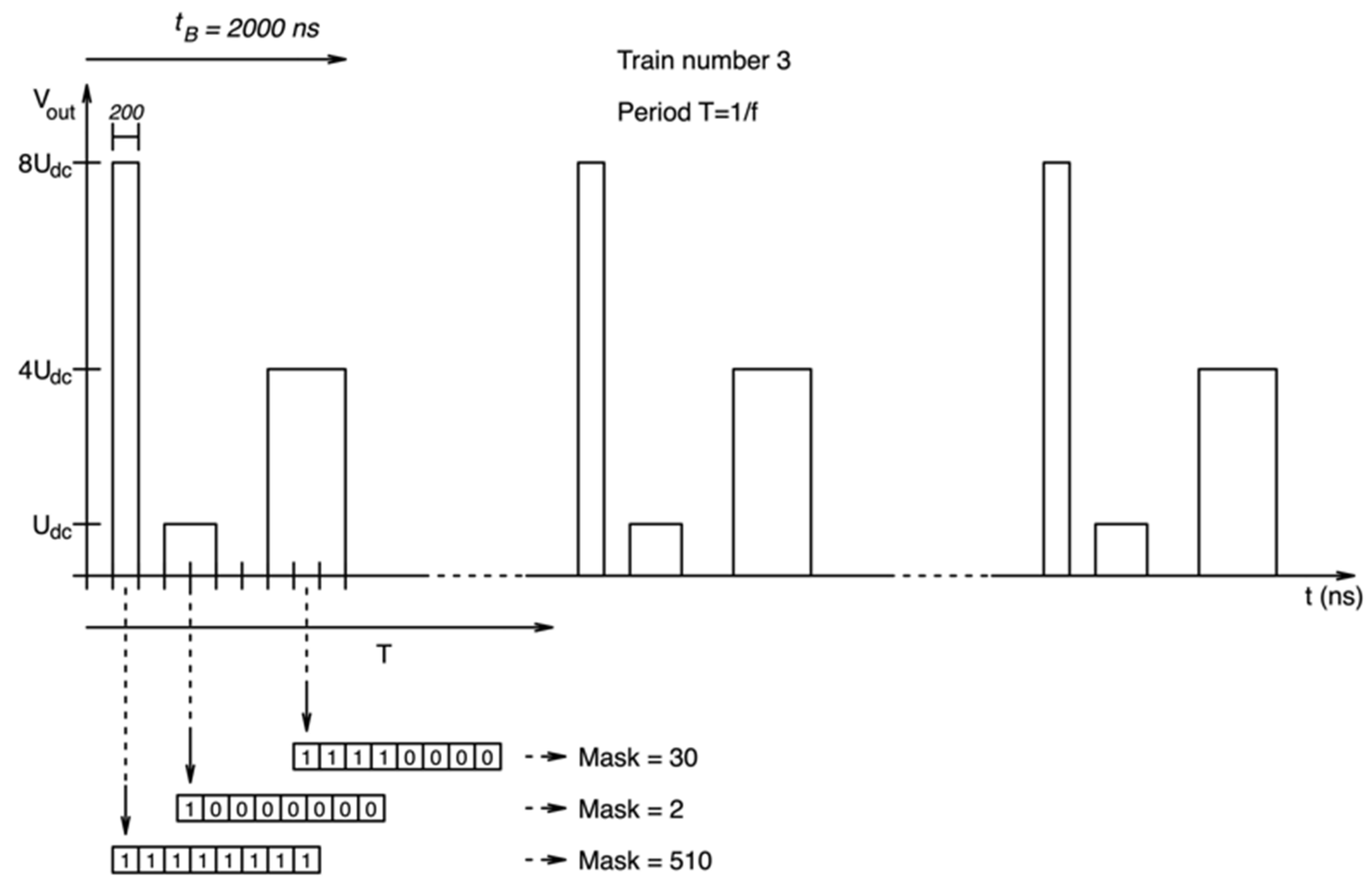
2.3. Marx Modulator Pulse Burst Sequence Programming

The control system includes three main components, as shown in Figure 1:
-
The computer user interface, which allows the user to define the timing and pulse amplitude sequence for the four channels, using a simple line command, using Pause in ns for the time before the pulse, Pulse in ns for the pulse time, and Mask for the amplitude control that defines the stages to trigger in each Marx;
-
The main control board that receives the information from the computer user interface and sets the pulse timing sequence and amplitude for each Marx modulator, sending this information by UART communication to each Marx. Additionally, once the trimming sequence and Mask is programmed in each MM, the trigger signals are sent to each modulator. The minimum step possible is 100 ns and the maximum pulse width, or burst time, is 100 µs;
-
The drive board k in each Marx that receives the timing sequence for all the pulse time of each Marx and the corresponding information when to turn-on or turn-off each stage during pulse trigger signal.
The main control board generates a time sequence with the time periods when there are pulses, which matches the trigger signal generation, for each Marx modulator. In parallel, the main control board sets for every pulse time period the Mask for each Marx.
The Mask is calculated by adding the value corresponding to the power of two, with index from 1 to 8, equal to the number of stages, of the stages that are on. For example, if all the stages are on, the Mask value is 510, if the first four stages are on, the Mask value is 30, if the first stage is on only, the Mask value is 2, and so on and so forth.
In order to generate a burst pulse sequence in each Marx, the user must define a command line as shown in Table 1, as an example, where the total pulse burst time, tB (equal to the sum of pause and pulse times), is identical in all the four channels. If, for one channel, the pulse sequence is not defined, or defined for a lower time, the output voltage is set to zero to the end of tB.
Figure 5 shows the output result, for one channel, of the pulse sequence defined in Table 1, where a train number of 3, for pulse sequence repetition, and a frequency f between each train number was defined, also, as shown in Figure 6.
For the example shown in Figure 5, the pulse time sequence defined was tB = 2000 ns, equal to the sum of all the Pause and Pulse times of the burst sequence, shown in Table 1. The time sequence is sent to the Marx generator with the Mask definition, which defines for each pulse time, which stages are on and off.
Although the minimum step is 100 ns, preliminary results were taken for a minimum pulse time of 200 ns, 2.5 MHz maximum frequency, for safety switching margin at Marx modulators. The user can define a time for the burst operation, tB, within certain limits, which is the same for each channel, from 0 to 4.

2.4. Marx Modulator Design

The specifications for the generator include the possibility to produce pulse burst of 6500 V, 65 A from 100 ns to 100 µs, with a maximum frequency of 5 MHz, on each channel, with a maximum 100 W average output power for the all generator. In addition, the possibility to set in each pulse burst, a time sequence with different pulse widths and amplitudes, for each channel independently.
Considering the above, each Marx modulator was assembled with 8 stages, for an Udc up to about 820 V. For the Spi and Sni switches TO-263-7 C3M0280090J SiC Cree MOSFETs (i.e., 900 V, 22 A pulsed current and 280 mΩ) were chosen. Considering the required pulse current of 65 A, two MOSFETs were placed in parallel in each switch Spi and Sci. Although the current presented on the datasheet is lower, the MOSFETs were tested up to 35 A each, at vgs ≈ 17.5 V, with good performance and no observed derating.
The pulse and charging switches were designed alike, since more than one channel can work simultaneously. Hence, is possible to have several operating conditions, depending on how the load is connected between the outputs, were one MM could be in pulse mode and another is charge mode, sinking the current from the first one. This operation is presented in the Results section, for bipolar operation, with the load connect to HV+ of two channels.
For each Marx modulator, the stage Ci capacitors, in Figure 2 circuit, has a capacitance of 0.75 µF, comprising five 0.15 µF/1000 V capacitors in parallel, reference B32653A0154 from TDK. The maximum energy stored inside each MM, Wg, for an input Udc of about 820 V, is about 2 J, from:
Wg = (n/2) Ci (Udc)2,
where n = 8. Considering the energy stored inside the MM, Wg, the maximum pulse energy, Wp, should be less than 5 times, 0.4 J, to have a maximum 10% pulse voltage droop, from:
Wp = n Udc Ip ton,
where n is the number of stages that participate in the pulse, Udc is the CCPS voltage, Ip the pulse current and ton the pulse width. This means that for a pulse of 6500 V and 65 A, having 10% voltage droop (i.e., 650 V), the maximum pulse width would be about 946 ns.
In addition, the operating frequency in single or burst series mode is limited by the HVPS 100 W, such that the time between pulses must be sufficient in order that the Marx capacitors are charged to the set voltage. Considering that the pulse duty cycle is normally less than 1%. A simple way to estimate the maximum pulse frequency is by:
f = P/Wg,
where P is the CCPS power, 100 W. Hence, for the example given above, the maximum pulse frequency would be 250 Hz.
In relation to the signal transmission, the TLP2367 series photocoupler was used, with 50-Mbps in small SO6 package, internal Faraday shield that provides a guaranteed common-mode transient immunity of ±25 kV/μs, and 3750 Vrms isolation voltage, with just 12 ns propagation delay time (i.e., the delay D used in Figure 4c are also of 12 ns).
A critical aspect with the pulse generator is current protection, as the load is biological, in order to protect the hardware and to keep the load from undesirable operating conditions that may lead to its destruction. Normally, problems arise from overcurrent’s and load short-circuit events, when the current rises too fast, due to the fact that the generator has low inductance to be able to produce fast pulses, and can overheat the biological load, by delivering excess energy, damaging the switches. In order to limit these types of issues, the proposed generator, in Figure 1, has two current protection modes:
(a)
A fast overcurrent protection, based on the classic desaturation technique, in the MOSFET drivers on each stage, both pulse and charge devices, which is very fast and cuts the gate signals if the current goes above a reference value [28]. This protection is set to 65 A, being proportional to the current level and detects the di/dt, also;
(b)
A slow overcurrent protection, based on the pulse output current measurement, from a current transformer, both in HV+ and HV− terminals, where it is possible to change the amplitude value of this protection, for increased safety in certain operating conditions. This protection can be set from 10 to 65 A, switching off all the stage drivers. A current transformer is placed on each HV+ output, which send the values to the “Trigger signals generation” board, being compared to a reference value set by the main control board. If the value sensed is above that reference level the trigger signal is switched off.
The value of 100 Ω was chosen for nominal load impedance. Being a direct capacitive discharge type of generator, it can work with any value of load, where for values equal and higher than 100 Ω, the constraints are due to the ratio between stored energy and pulse energy, and power, as explained above. For impedance values below 100 Ω, besides these constraints, also the voltage amplitude should be reduced in order to limit the maximum current to 65 A. The target value of 100 Ω was chosen because several electroporation experimental procedures present impedance between 50 and 200 Ω, or more. Such when electrodes are used for microscope exposure setup [13,29,30,31], as well as when electrodes are used for exposures of cell monolayers and 3D cultures [11,32,33,34], and in most in vivo stimulation/ablation electrodes [35,36,37].

3. Results

The implemented four channels generator is shown in Figure 6, which is enclosed in a grounded 19” stainless steel box, with air cooling. The generator was tested using resistive loads. Unless described otherwise, voltage waveforms were recorded with a Tektronix TDS3012B 100 MHz 1.25 GS/s oscilloscope, using PMK PHV1000 100:1, 400 MHz, 50 MΩ/7.5 pF high voltage probe. The current measurements were recorded using a Bergoz CT-D0.5-B current transformer.

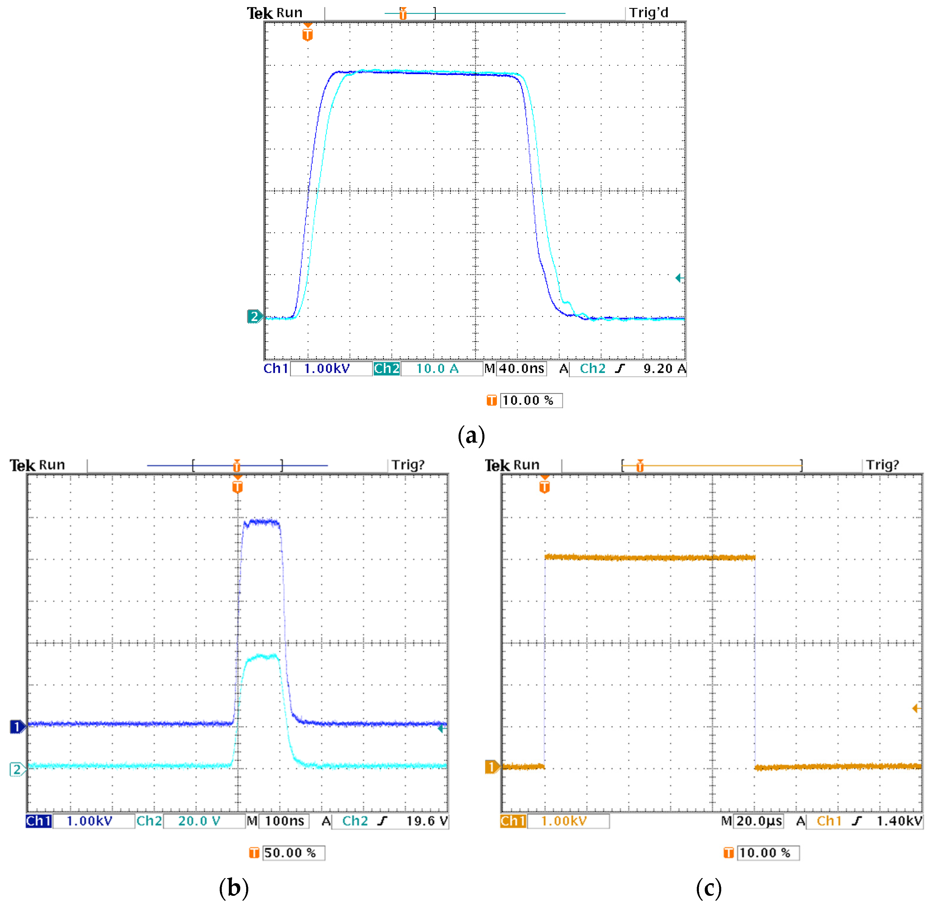
3.1. Single Channel Operation

The basic function of the generator is the single channel operation, where a load is connected between terminals, HV+ and HV−, of one channel. In Figure 7, the pulse output voltage and current for operation with channel 0, considering a resistive load, connect between HV+ and HV−, is shown. In Figure 7a, a single pulse of, almost, 6 kV and 60 A with 200 ns is applied to a 100 Ω load. The pulse has, about, 30 ns rise and fall times. The pulse was generated by the command at the computer user interface shown in Table 2, where the Mask = 510 means that all the stages, in the selected MM, are on during the pulse, applying the full voltage, i.e., 8Udc, being Udc = 750 V. The 5 ns delay in the current waveform, shown in Figure 7a, relative to the voltage waveform, is due to a longer cable used on this situation.
Considering now Udc = 625 V, Figure 7b shows a single pulse of 100 ns on 100 Ω and Figure 7c shows a single pulse of 100 µs on 1 MΩ load, command lines on Table 2.
In addition, in simple pulse operation, Channel 0, Figure 8 shows a burst sequence of pulses with various amplitudes, time between pulses and pulse widths, as detailed in Table 3, with an input voltage from the CCPS of Udc = 750 V.
Figure 8 shows, also, a small voltage droop during the pulse period. This voltage droop depends on the ratio of pulse energy to stored energy in MM, for a given voltage. It is worth noting that the CCPS is always charging the MMs, even during burst. Nevertheless, the 100 W available are for the four MMs.
In relation to the Mask values, shown in Table 3, the user can select any stage in a MM for on–off operation, so the values of the Mask can change for equal number of stages on–off.

3.2. Multi-Channel Operation

The main advantage of this generator is the possibility to work with 4 independent output channels, simultaneously applying different pulse protocols to the load. Figure 9 shows an example of this multi-channel operation with the load connected between the HV+ terminals of two channels, 0 and 1; one pulse is generated in each channel with a time delay, generating a bipolar pulse in a resistive load.
Table 4 shows the pulse command line in the two channels, 0 and 1, considering an input voltage of Udc = 625 V, i.e., 8Udc= 5 kV.
As shown in Figure 9, a bipolar symmetric pulse of approximately 5 kV, 50 A, and 200 ns width is applied to a 100 Ω load, with 250 ns time between pulses. The bipolar pulse has about 30 ns rise and fall times in both positive and negative pulses. Although the pulses shown in Figure 9 are shifted, it is possible to define a command line where pulses can be applied to different channels at the same time.
Another example of the multi-channel operation, using all the 4 channels is presented in Figure 10, where two shifted bipolar pulses with decreasing amplitude are generated. One between HV+ terminals of channels 0 and 1 and the other between HV+ terminals of channels 2 and 3. The command line for Figure 10 is described in Table 5, for each MM.

3.3. Protections Operation

Figure 11 shows the overcurrent protections in action, with a load of approximately 10 Ω, for an output voltage of about 700 V in Channel 0. The first result, Figure 11a, shows the slow protection in action for a set value of 40 A, where this value can be set from 10 A to 65 A. The time response observed is about 150 ns, due to the current measurement loop from the current transformer to the main control board, which switches off all the stage in MM0. Instead, the fast protection (i.e., 10 ns to 20 ns response), switches off the individual stages that sense this current limit, as shown in Figure 11b.
The value of the output overcurrent protection can be set via software and the protection can be turned on–off.

4. Discussion

The developed device can generate pulses from 100 ns to 100 µs, up to 6.5 kV and 65 A with maximum repetition rate of 5 MHz, from 4 independent and synchronized Marx modulators.
The pulse generator was evaluated on resistive type loads connected at the HV+ and HV− terminals, from 100 Ω to 1 MΩ. Unipolar, symmetric and asymmetric bipolar pulses were successfully generated (Figure 7, Figure 8, Figure 9 and Figure 10). In addition, synchronized shifted bipolar asymmetric pulses were generated in Figure 10. For all reported pulses, rise and fall times were in the order of 30 ns, which allowed for the generation of almost rectangular pulses.
The maximum energy stored energy in the Marx modulators, for input voltage of 820 V, is 2 J, enabling the generation of 6.5 kV and 65 A with almost 950 ns, for voltage droop less than 10%, and burst repetition rate up to 250 Hz.
While there are pulsed generators reported in the literature that can generate high-voltage and high-frequency asymmetric bipolar pulses [12,13,14,15]. The main innovation of the presented generator is the ability to generate, also, two synchronized asymmetric pulses, and so extending the possibilities for new research progresses [16,17,18], due to the 4 independent Marx modulators, operated synchronously.
Finally, the current protections described, slow and fast, seen in Figure 11, contribute to the reliability of the generator, the safety of the application, mainly for long pulse operation, being adjustable by software, which is not seen to this extend in the literature for this type of pulse generator.

Author Contributions

Conceptualization, A.K., L.R. and A.G.P.; methodology, A.K., U.S. and L.R.; software, U.S.; validation, A.K., L.R. and A.G.P.; formal analysis, A.K., U.S., L.R. and A.G.P.; investigation, A.K., L.R. and A.G.P.; writing—original draft preparation, L.R. and A.K.; writing—review and editing, L.R. and A.K. All authors have read and agreed to the published version of the manuscript.

Funding

EnergyPulse Systems.

Institutional Review Board Statement

Not applicable.

Informed Consent Statement

Not applicable.

Data Availability Statement

The data presented in this paper is available on request from the corresponding author. A.K., L.R., U.S. and A.G.P.

Conflicts of Interest

The authors declare no conflict of interest.

References

  1. Butkus, P.; Murauskas, A.; Tolvaišienė, S.; Novickij, V. Concepts and Capabilities of In-House Built Nanosecond Pulsed Electric Field (nsPEF) Generators for Electroporation: State of Art. Appl. Sci. 2020, 10, 4244. [Google Scholar] [CrossRef]
  2. Chopinet, L.; Rols, M.P. Nanosecond electric pulses: A mini-review of the present state of the art. Bioelectrochemistry 2015, 103, 2–6. [Google Scholar] [CrossRef]
  3. Batista Napotnik, T.; Reberšek, M.; Vernier, P.T.; Mali, B.; Miklavčič, D. Effects of high voltage nanosecond electric pulses on eukaryotic cells (In Vitro): A systematic review. Bioelectrochemistry 2016, 110, 1–12. [Google Scholar] [CrossRef] [PubMed] [Green Version]
  4. Kotnik, T.; Frey, W.; Sack, M.; Meglič, S.H.; Peterka, M.; Miklavčič, D. Electroporation-based applications in biotechnology. Trends Biotechnol. 2015, 33, 480–488. [Google Scholar] [CrossRef] [PubMed]
  5. Rao, X.; Chen, X.; Zhou, J.; Zhang, B.; Alfadhl, Y. Design of a High Voltage Pulse Generator with Large Width Adjusting Range for Tumor Treatment. Electronics 2020, 9, 1053. [Google Scholar] [CrossRef]
  6. Garner, A.L.; Caiafa, A.; Jiang, Y.; Klopman, S.; Morton, C.; Torres, A.S.; Loveless, A.M.; Neculaes, V.B. Design, characterization and experimental validation of a compact, flexible pulsed power architecture for ex vivo platelet activation. PLoS ONE 2017, 12, e0181214. [Google Scholar] [CrossRef] [Green Version]
  7. Yao, C.; Lv, Y.; Dong, S.; Zhao, Y.; Liu, H. Irreversible electroporation ablation area enhanced by synergistic high- and low-voltage pulses. PLoS ONE 2017, 12, e0173181. [Google Scholar] [CrossRef] [Green Version]
  8. Sweeney, D.C.; Reberšek, M.; Dermol, J.; Rems, L.; Miklavčič, D.; Davalos, R.V. Quantification of cell membrane permeability induced by monopolar and high-frequency bipolar bursts of electrical pulses. Biochim. Biophys. Acta Biomembr. 2016, 1858, 2689–2698. [Google Scholar] [CrossRef]
  9. Yao, C.; Dong, S.; Zhao, Y.; Lv, Y.; Liu, H.; Gong, L.; Ma, J.; Wang, H.; Sun, Y. Bipolar Microsecond Pulses and Insulated Needle Electrodes for Reducing Muscle Contractions during Irreversible Electroporation. IEEE Trans. Biomed. Eng. 2017, 64, 2924–2937. [Google Scholar] [CrossRef]
  10. Latouche, E.L.; Arena, C.B.; Ivey, J.W.; Garcia, P.A.; Pancotto, T.E.; Pavlisko, N.; Verbridge, S.S.; Davalos, R.V.; Rossmeisl, J.H. High-Frequency Irreversible Electroporation for Intracranial Meningioma: A Feasibility Study in a Spontaneous Canine Tumor Model. Technol. Cancer Res. Treat. 2018, 1, 17. [Google Scholar] [CrossRef]
  11. Sano, M.; Arena, C.B.; Bittleman, K.R.; DeWitt, M.R.; Cho, H.J.; Szot, C.S.; Saur, D.; Cissell, J.M.; Robertson, J.; Lee, Y.W.; et al. Bursts of Bipolar Microsecond Pulses Inhibit Tumor Growth. Sci. Rep. 2015, 5, 14999. [Google Scholar] [CrossRef] [Green Version]
  12. Pirc, E.; Miklavčič, D.; Uršič, K.; Serša, G.; Reberšek, M. High-Frequency and High-Voltage Asymmetric Bipolar Pulse Generator for Electroporation Based Technologies and Therapies. Electronics 2021, 10, 1203. [Google Scholar] [CrossRef]
  13. Valdez, C.M.; Barnes, R.A.; Roth, C.C.; Moen, E.K.; Throckmorton, G.A.; Ibey, B.L. Asymmetrical bipolar nanosecond electric pulse widths modify bipolar cancellation. Sci. Rep. 2017, 7, 16372. [Google Scholar] [CrossRef] [PubMed] [Green Version]
  14. van Es, R.; Konings, M.K.; Du Pré, B.C.; Neven, K.; van Wessel, H.; van Driel, V.J.H.M.; Westra, A.H.; Doevendans, P.A.F.; Wittkampf, F.H.M. High-frequency irreversible electroporation for cardiac ablation using an asymmetrical waveform. Biomed. Eng. Online 2019, 18, 75. [Google Scholar] [CrossRef] [Green Version]
  15. Sano, M.B.; Fan, R.E.; Xing, L. Asymmetric Waveforms Decrease Lethal Thresholds in High Frequency Irreversible Electroporation Therapies. Sci. Rep. 2017, 7, 40747. [Google Scholar] [CrossRef] [PubMed] [Green Version]
  16. Kim, V.; Gudvangen, E.; Kondratiev, O.; Redondo, L.; Xiao, S.; Pakhomov, A. Peculiarities of Neurostimulation by Intense Nanosecond Pulsed Electric Fields: How to Avoid Firing in Peripheral Nerve Fibers. Int. J. Mol. Sci. 2021, 22, 7051. [Google Scholar] [CrossRef] [PubMed]
  17. Pakhomov, A.G.; Gudvangen, E.; Xiao, S.; Semenov, I. Interference targeting of bipolar nanosecond electric pulses for spatially focused electroporation, electrostimulation, and tissue ablation. Bioelectrochemistry 2021, 141, 107876. [Google Scholar] [CrossRef]
  18. Gianulis, E.C.; Casciola, M.; Zhou, C.; Yang, E.; Xiao, S.; Pakhomov, A.G. Selective distant electrostimulation by synchronized bipolar nanosecond pulses. Sci. Rep. 2019, 9, 13116. [Google Scholar] [CrossRef]
  19. Rubin, A.E.; Levkov, K.; Usta, O.B.; Yarmush, M.; Golberg, A. IGBT-Based Pulsed Electric Fields Generator for Disinfection: Design and In Vitro Studies on Pseudomonas aeruginosa. Ann. Biomed. Eng. 2019, 47, 1314–1325. [Google Scholar] [CrossRef]
  20. Wang, C.; Zhang, Q.H.; Streaker, C. A 12 kV solid state high voltage pulse generator for a bench top PEF machine. In Proceedings of the IEEE 3rd International Conference on Power Electronics and Motion Control, Beijing, China, 15–18 August 2000; Volume 3, pp. 1347–1352. [Google Scholar]
  21. Mi, Y.; Bian, C.; Wan, J.; Xu, J.; Yao, C.; Li, C. A Modular Solid-State Nanosecond Pulsed Generator Based on Blumlein-Line and Transmission Line Transformer with Microstrip Line. IEEE Trans. Dielectr. Electr. Insul. 2017, 24, 2196–2202. [Google Scholar] [CrossRef]
  22. Pirc, E.; Miklavcic, D.; Rebersek, M. Nanosecond Pulse Electroporator with Silicon Carbide MOSFETs: Development and Evaluation. IEEE Trans. Biomed. Eng. 2019, 66, 3526–3533. [Google Scholar] [CrossRef] [PubMed]
  23. Redondo, L.M.; Zahyka, M.; Kandratsyeu, A. Solid-State Generation of High-Frequency Burst of Bipolar Pulses for Medical Applications. IEEE Trans. Plasma Sci. 2019, 47, 4091–4095. [Google Scholar] [CrossRef]
  24. Yao, C.; Dong, S.; Zhao, Y.; Mi, Y.; Li, C. A Novel Configuration of Modular Bipolar Pulse Generator Topology Based on Marx Generator with Double Power Charging. IEEE Trans. Plasma Sci. 2016, 44, 1872–1878. [Google Scholar] [CrossRef]
  25. Abdelsalam, I.; Elgenedy, M.A.; Ahmed, S.; Williams, B.W. Full-Bridge Modular Multilevel Submodule-Based High-Voltage Bipolar Pulse Generator with Low-Voltage DC, Input for Pulsed Electric Field Applications. IEEE Trans. Plasma Sci. 2017, 45, 2857–2864. [Google Scholar] [CrossRef] [Green Version]
  26. Jiang, W.; Oshima, N.; Yokoo, T.; Yatsui, K.; Takayama, K.; Wake, M.; Shimizu, N.; Tokuchi, A. Development of Repetitive Pulsed Power Generators Using Power Semiconductor Devices. IEEE Pulsed Power Conf. 2005, 1167–1172. [Google Scholar] [CrossRef]
  27. Redondo, L.M.; Silva, J.F. Repetitive High-Voltage Solid-State Marx Modulator Design for Various Load Conditions. IEEE Trans. Plasma Sci. 2009, 37, 1632–1637. [Google Scholar] [CrossRef]
  28. Mocevic, S.; Wang, J.; Burgos, R.; Boroyevich, D.; Stancu, C.; Jaksic, M.; Peaslee, B. Comparison between desaturation sensing and Rogowski coil current sensing for short-circuit protection of 1.2 kV, 300 A SiC MOSFET module. In Proceedings of the 2018 IEEE Applied Power Electronics Conference and Exposition (APEC), San Antonio, TX, USA, 4–8 March 2018; pp. 2666–2672. [Google Scholar] [CrossRef]
  29. Michel, O.; Pakhomov, A.G.; Casciola, M.; Saczko, J.; Kulbacka, J.; Pakhomova, O.N. Electro permeabilization does not correlate with plasma membrane lipid oxidation. Bioelectrochemistry 2020, 132, 107433. [Google Scholar] [CrossRef]
  30. Bo, W.; Silkunas, M.; Mangalanathan, U.; Novickij, V.; Casciola, M.; Semenov, I.; Xiao, S.; Pakhomova, O.N.; Pakhomov, A.G. Probing Nano electroporation and Resealing of the Cell Membrane by the Entry of Ca2+ and Ba2+ Ions. Int. J. Mol. Sci. 2020, 21, 3386. [Google Scholar] [CrossRef]
  31. Sozer, E.B.; Pocetti, C.F.; Vernier, P.T. Asymmetric Patterns of Small Molecule Transport After Nanosecond and Microsecond Electropermeabilization. J. Membr. Biol. 2018, 251, 197–210. [Google Scholar] [CrossRef] [PubMed] [Green Version]
  32. Liu, H.; Zhao, Y.; Yao, C.; Schmelz, E.M.; Davalos, R.V. Differential effects of nanosecond pulsed electric fields on cells representing progressive ovarian cancer. Bioelectrochemistry 2021, 142, 107942. [Google Scholar] [CrossRef]
  33. Newman, J.; Jauregui, L.; Knape, W.A.; Ebbers, E.; Uecker, D.; Mehregan, D.; Nuccitelli, R. A dose-response study of nanosecond electric energy pulses on facial skin. J. Cosmet. Laser Ther. 2020, 22, 195–199. [Google Scholar] [CrossRef]
  34. Hruza, G.J.; Zelickson, B.D.; Selim, M.M.; Rohrer, T.E.; Newman, J.; Park, H.; Jauregui, L.; Nuccitelli, R.; Knape, W.A.; Ebbers, E.; et al. Safety and Efficacy of Nanosecond Pulsed Electric Field Treatment of Seborrheic Keratoses. Dermatol. Surg. 2019, 46, 1183–1189. [Google Scholar] [CrossRef] [PubMed]
  35. Nuccitelli, R.; McDaniel, A.; Anand, S.; Cha, J.; Mallon, Z.; Berridge, J.C.; Uecker, D. Nano-Pulse Stimulation is a physical modality that can trigger immunogenic tumor cell death. J. Immunother. Cancer 2017, 5, 32. [Google Scholar] [CrossRef] [Green Version]
  36. Nuccitelli, R.; Berridge, J.C.; Mallon, Z.; Kreis, M.; Athos, B.; Nuccitelli, P. Nanoelectroablation of Murine Tumors Triggers a CD8-Dependent Inhibition of Secondary Tumor Growth. PLoS ONE 2015, 10, e0134364. [Google Scholar] [CrossRef] [Green Version]
  37. Nuccitelli, R.; Huynh, J.; Lui, K.; Wood, R.; Kreis, M.; Athos, B.; Nuccitelli, P. Nanoelectroablation of human pancreatic carcinoma in a murine xenograft model without recurrence. Int. J. Cancer 2013, 132, 1933–1939. [Google Scholar] [CrossRef]
Figure 1. General schematic layout of the four channels generator, including: capacitor charging power supply, CCPS; four Marx modulators, MM; main control board and trigger signals generation board; PC user interface.
Applsci 11 11782 g001
Figure 2. Simplified schematic of the positive Marx modulator.
Applsci 11 11782 g002
Figure 3. Auxiliary power supply, PS, in each Marx modulator, supplying power to the stage switches.
Applsci 11 11782 g003
Figure 4. (a) Schematic of a generic switch driver board k used for driving each switch in Marx generator of Figure 2, placed at voltage reference k. (b) Simplified schematic of the opto-coupler association for the UART communication. (c) Simplified schematic of the opto-coupler association for the trigger signal transmission for each MM.
Applsci 11 11782 g004aApplsci 11 11782 g004b
Figure 5. Example of pulse burst sequence defined from Table 1, with train number 3 and frequency f.
Applsci 11 11782 g005
Figure 6. Top view of the 19” rack of the four channels generator, 506 length, 430 width, and 174 mm height: (A) The four Marx modulators; (B) main control board; (C) capacitor charging power supply; (D) auxiliary circuits, power supplies, and trigger signal generation board; (E) voltage pulses output, protections, current, and voltage measurement.
Applsci 11 11782 g006
Figure 7. Generator single pulse operation: (a) 200 ns on 100 Ω: (blue) output voltage 1 kV/div; (cyan) output current 10 A/div; 40 ns/div; (b) 100 ns pulse on 100 Ω: (blue) output voltage 1 kV/div; (cyan) output current 20 A/div; 100 ns/div; (c) 100 µs pulse on 1 MΩ: output voltage 1 kV/cm; 20 µs/div.
Applsci 11 11782 g007
Figure 8. Single pulse operation of the generator, with various pulse widths and amplitudes during one burst: (blue) output current 10 A/div, 400 ns/div.
Applsci 11 11782 g008
Figure 9. Symmetric bipolar pulse operation, between MM0 and MM1, of the generator: (blue) output current of MM0, 20 A/div; (cyan) output current of MM1, 20 A/div; 100 ns/div.
Applsci 11 11782 g009
Figure 10. (a) Asymmetric bipolar pulse operation, between MM0 and MM1 (blue), between MM2 and MM3 (cyan) of the generator: (blue) output current of MM0, 20 A/div; (cyan) output current of MM12 20 A/div; 400 ns/div. (b) Zoom of (a), 100 ns/div.
Applsci 11 11782 g010
Figure 11. (a) Slow overcurrent protection, operating at 40 A. (b) Fast overcurrent protection, operating at 65 A. (blue) output voltage, 100 V/div; (cyan) output current, 10 A/div; 100 ns/div.
Applsci 11 11782 g011
Table 1. Example of command line of a pulse sequence for MM 0, for three pulses.
# MM0Pause (ns)Pulse (ns)MaskStages on
12002005108
220040021
3400600304
Table 2. Single channel command line for the pulse sequence shown in Figure 7.
# MM0Pause (ns)Pulse (ns)MaskStages on
(a) 12002005108
(b) 12001005108
(c) 1200100,0005108
Table 3. Single channel command line for the pulse sequence shown in Figure 8.
# MM0Pause (ns)Pulse (ns)MaskStages on
12502505108
230030062
32504502547
45001100304
Table 4. Dual channel command line for the pulse sequence shown in Figure 9.
# MM0Pause (ns)Pulse (ns)MaskStages on
12002505108
# MM1Pause (ns)Pulse (ns)MaskStages on
12002505108
Table 5. Multi-channel command line for the pulses sequence shown in Figure 10.
# MM0Pause (ns)Pulse (ns)MaskStages on
1 2502505108
22502501266
3250250304
425025062
# MM1Pause (ns)Pulse (ns)MaskStages on
1 5002502547
2250250625
3250250143
425025021
# MM2Pause (ns)Pulse (ns)MaskStages on
1 7502505108
22502501266
3250250304
425025062
# MM3Pause (ns)Pulse (ns)MaskStages on
1 10002505107
22502501265
3250250303
425025061
Publisher’s Note: MDPI stays neutral with regard to jurisdictional claims in published maps and institutional affiliations.

