Abstract
Using a sample coated with three types of carbon-based paints, namely single-wall carbon nanotube (SWCNTs), carbon black, and graphite, the amount of radio wave absorption for each was measured. SWCNTs proved to have the superior radio wave absorption effect in the millimeter band. Considering the change in the amount of radio wave absorption depending on the coating amount, three different coating thicknesses were prepared for each test material. The measurement frequency was set to two frequency bands of 28 GHz and 75 GHz, and the measurement method was carried out based on Japanese Industrial Standard (JIS) R1679 “Radio wave absorption characteristic measurement method in the millimeter wave band of the radio wave absorber.” As for the amount of radio wave absorption in the 28 GHz band, a maximum amount of radio wave absorption of about 6 dB was obtained when 35 m of CNT spray paint was applied. It was confirmed that the carbon black paint came to about 60% that of the SWCNT, and the graphite paint did not obtain much radio wave absorption even when the coating thickness was changed. Furthermore, even in the 75 GHz band, the radio wave absorption was about 7 dB when 16 μm of CNT spray paint was applied, showing the maximum value. Within these experimental results, the CNT spray paint has a higher amount of radio wave absorption in the millimeter wave band than paints using general carbon materials. Its effectiveness could be confirmed even with a very thin coating thickness of 35 μm or less. It was also confirmed that even with the same paint, the radio wave absorption effect changes depending on the difference in coating thickness and the condition of the coated surface.
1. Introduction
The environment surrounding us is undergoing major changes, such as the spread of infectious diseases on a global scale and the increasing scale of natural disasters. In tackling these political, economic, and social issues, we must work towards a “safe and secure society.” In the field of wireless technology, 5G, IoT, millimeter-wave imaging technology, etc., are being rapidly developed as newer necessary technologies to realize a “safe and secure society”. Although those newer technologies have not enjoyed extensively widespread use until more recently, the utilization of a frequency band called millimeter waves is drawing particular attention [1].
Millimeter waves are radio waves with a frequency of 30 GHz to 300 GHz and a wavelength of 1 cm to 1 mm. Within radio waves, they are in a frequency band closer to light, and have properties relatively similar to light. They have a very strong straightness and cannot transmit far, but they have a large transmission capacity and are capable of high-speed data communication [2]. On the other hand, with millimeter waves, which are rapidly being used in various technologies, there is concern that the radio wave environment will deteriorate due to interference. Thus, there is an urgent need to develop technology to control the radio wave environment.
In recent years, attention has been focused on various shapes of micro/nanostructures, such as rods, tubes, beams, plates, and shells, and their mechanical behaviors [2]. In particular, carbon nanotubes are attracting attention. CNTs are tubular, fibrous, one-dimensional materials consisting only of carbon with a diameter of nanometers [3]. CNTs are extremely lightweight because their constituents are only carbon atoms. CNTs can be classified into single-walled carbon nanotubes (SWCNTs) and multiwalled carbon nanotubes (MWCNTs) according to their structure (see Figure 1).
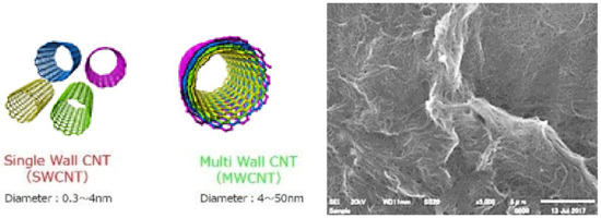
Figure 1.
Illustration of SWCNTs and MWCNTs and a photo of dispersed SWCNTs (SEM 5000×).
Reinforced composites such as carbon nanotubes are new nanomaterials, and their mechanical behavior has recently been attention-grabbing in materials science and engineering science due to their excellent mechanical and electrical properties after fusion with a matrix [4,5].
The radio wave absorption effect of SWCNTs (single-walled carbon nanotubes) is attracting attention as a technology for controlling the radio wave environment, but its specific characteristics have not yet been fully studied.
By comparing the radio wave absorption effect in the millimeter wave band within conventionally used carbon-based material and SWCNTs in this paper, the purpose of the study is to verify the possibility of using SWCNTs as radio wave absorbers for the millimeter wave band.
2. Background of Electromagnetic Absorption
Various electromagnetic waves are widely used in many areas, making our daily lives convenient [6]. For example, a wide variety of electromagnetic wave-based electronic devices such as mobile phones, WiFi, Bluetooth, Near Field Communication (NFC), and wireless charging have been developed and play important roles [7,8]. So, the widespread practical application of various electronic devices and dense systems will cause electromagnetic interference (EMI), which might cause more and more serious problems, such as the malfunction of electronic devices and effects on the human body [9]. Moreover, the wireless devices we use generate unwanted electromagnetic waves that affect other wireless devices [10].
In recent years, as represented by fifth-generation mobile communication systems (5G) and autonomous driving, the frequency band of electromagnetic waves used has been expanded to high frequency bands including millimeter waves. Therefore, there is an urgent need to develop electromagnetic shielding materials and establish evaluation methods [11]. Accordingly, the development of the latest radio wave absorbers and electromagnetic shielding materials using artificial materials that do not exist in the natural world, and evaluation methods, are being researched [12,13]. The artificial material referred to here is a two-dimensional or three-dimensional periodic arrangement of metal wires, metal patterns, and so on. Their radiometric characteristics are significantly different from those of ordinary conductive materials, dielectrics, and magnetic materials existing in nature.
In the field of electromagnetic wave-shielding research, electromagnetic wave-shielding measures for suppressing noise caused by electronic devices and electrical automobile components, electromagnetic wave radiation reduction measures for semiconductor packages, and electromagnetic wave-shielding measures for medical facilities and studios have been implemented. Research on shielding measures in necessary facilities and evaluation methods for electromagnetic wave shielding performance are also being conducted [14]. In addition, compared to the fourth-generation mobile communication system (4G) and wireless LAN radio, the fifth-generation mobile communication system (5G), which shifts to a higher frequency band, uses millimeter-wave band frequencies, meaning radio waves can be used. Due to the strength of straightness, it seems that the shield has a large effect on the radio wave propagation characteristics. Since this will have a great impact on indoor and outdoor coverage areas, research on the analysis and evaluation of the radio wave environment with consideration to the shielding-loss characteristics of vehicles and human bodies is also underway [15].
On the other hand, in the field of radio wave absorber research, it is ideal to have a wide band and high absorption performance. However, recently, a radio wave absorber with a narrow band absorption performance specialized for a specific purpose and having various added values such as thinning and weight reduction has been proposed [14,15,16,17]. Furthermore, in the research field on the evaluation of material constants of absorbent materials, various measuring methods for a high frequency region which have been difficult to measure in the past have been proposed. This has become possible since the performance of measuring instruments such as vector network analyzers have been dramatically improved. In this way, research and development of electromagnetic wave absorbers and electromagnetic wave-shielding materials are expected to become more and more important as their use in various fields expands in the near future.
Currently, a sheet type of commercialized electromagnetic wave-shielding material, a mixture of rubber and carbon-based material, is the mainstream [14,18,19,20,21,22,23]. These electromagnetic wave-shielding materials are not elastic, are difficult to install in uneven or curved parts, and may be peeled off in deformed parts, so that they are difficult to install. As a method to solve such problems, a CNT paint has been developed in which various carbon-based materials including CNT are well dispersed. S. Chiba and M. Waki have succeeded in spraying carbon nanotubes (CNTs) by treating and dispersing them via a special method (see Figure 2). The spray using ZEON’s SWCNTs (ZEONANO®-SG101, Zeon corp., Tokyo, Japan) is particularly excellent. This CNT paint can be applied by spraying it like a general paint, and it can be easily applied to uneven or curved parts. Moreover, since it has elasticity, it is difficult to peel off even if it is applied to a deformed part. It is also easy to install on structures that have already been installed [24,25,26,27].
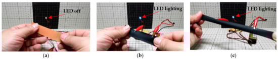
Figure 2.
Ultraflexible, thin film electrode formation with CNT spray: (a) Before applying the CNT spray; (b) After applying the CNT spray; (c) Even when stretched greatly, the LED remains on and the LED lights up.
As an example of special usage, attempts have been made to improve the amount of power generation by absorbing as many electromagnetic waves as possible in a photovoltaic power generation system [28,29]. Other research focuses on the stealth effect [27].
3. Experimental Procedure
3.1. Purpose of the Experiment
The purpose was to measure the amount of radio wave absorption of three types of carbon-based paints, including CNT spray paints, and to verify the superiority of CNT spray paints. As for the sample material, three thicknesses of each sample material were prepared in consideration of the influence of the coating amount. The frequencies to be verified were two frequency bands, the 28 GHz band used for 5G and the like and the 75 GHz band used for in-vehicle radar systems. The 77 GHz band is used for the in-vehicle radar system, but within this experiment, the measurement was performed at 75 GHz due to the equipment. The measurement method was carried out based on the Japanese Industrial Standard (JIS) R1679’s “Radio wave absorption characteristic measurement method in the millimeter wave band of the radio wave absorber” [30].
3.2. Sample Preparation
The sample material used for the verification of the radio wave absorption effect was prepared using a foamed polypropylene plate with a width of 170 mm, a height of 225 mm, a thickness of 3 mm and a smooth surface (See Figure 3).
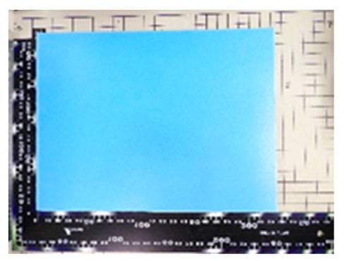
Figure 3.
Foamed polypropylene plate before painting.
The paints used for the test material were three types of carbon-based paints, SWCNTs, carbon black, and graphite, which were manually applied to the foamed polypropylene plate using a general spray gun. This work was performed by Fukoku Co., Ltd. (Saitama, Japan) [31]. The coating thickness was calculated by measuring the thickness of the sample material before and after coating with a micrometer and calculating the difference. Figure 4a–c shows the various test materials created.
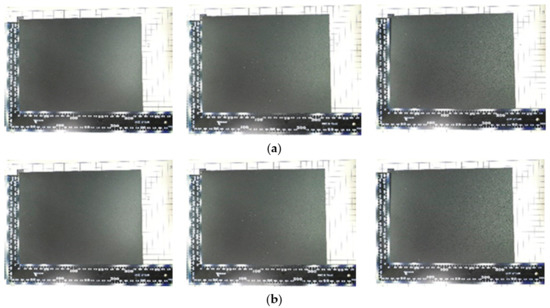
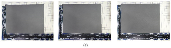
Figure 4.
Each sample used for verification: (a) CNT spray paint. Coating thickness: 16 μm [left], 35 μm [middle], 76 μm [right]; (b) Carbon black paint: Coating thickness: 16 μm [left], 35 μm [middle], 76 μm [right]; (c) Graphite paint: Coating thickness: 15 μm [left], 36 μm [middle], 74 μm [right].
3.3. Equipment for Verifying Radio Wave Absorption Effect
3.3.1. Outline of the Radio Wave Absorption Verification System
The outline of the verification system is shown in Figure 5.
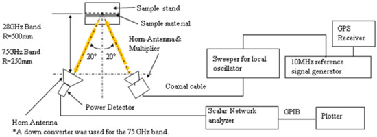
Figure 5.
Outline of the radio wave absorption verification system.
The radio wave absorption verification system is roughly divided into a transmission system and a reception system:
The transmission system consists of Sweep Generator (HP 8350B & 83595A) and Multiplier (HP 83554A). By multiplying the 13.25 GHz to the 14.75 GHz RF signal oscillated from the Sweep Generator by Multiplier, an RF signal from 26.5 GHz to 29.5 GHz is created and transmitted from the horn antenna for transmission. The receiving system consists of a Scalar network analyzer (WILTRON 562) and an RF Detector (WILTRON 560-7K50). The RF signal received from the receiving horn antenna is detected by the RF Detector and transmitted by the Scalar network analyzer. The loss is measured. Figure 6 shows the Sweep Generator (HP 8350B & 83595A) and the Scalar network analyzer (WILTRON 562).
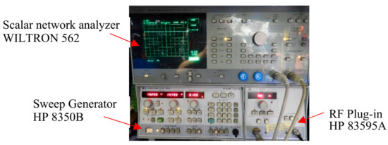
Figure 6.
Sweep Generator (HP 8350B & 83595A) and Scalar network analyzer (WILTRON 562).
3.3.2. Antenna Installation Position
The transmitting and receiving horn antennas should be installed in the Franhofer area. The distance (R) that gives the boundary between the Fresnel region and the Franhofer region can be calculated from the directional gain (Gd) of the horn antenna, π is Pi, and the free space wavelength (λ) of the transmission/reception frequency. (Refer to JIS R1679) [30].
R = Gdλ/2π
The directivity gain (Gd) of the Horn Antenna can be calculated from the effective maximum dimension (Dm) of the aperture surface, Pi (π) and the free space wavelength (λ) of the transmission/reception frequency (Refer to JIS R1679) [26].
Gd = 4πDm2/λ2
The distance that gives the boundary between the Fresnel region and the Franhofer region in each frequency band calculated using Equation (1) is shown below:
In the 28 GHz band, assuming that the test frequency is 28 GHz and the directional gain of the antenna is 14.5 dB, the distance that gives the boundary between the Fresnel region and the Franhofer region is calculated to be 243.7 mm. The position where the transmitting and receiving horn antennas were actually installed was set to 500 mm, which is about twice the distance of the boundary between the Fresnel region and the Franhofer region. In the 75 GHz band, each antenna was installed at a position of 250 mm. This is also about twice the distance of the boundary between the Fresnel region and the Franhofer region calculated from each condition. In this experiment, the nominal value was used for the antenna directivity gain (Gd), but if the gain was not disclosed, it could be calculated using Equation (2).
3.3.3. Outline of Antenna for 28 GHz Band
Figure 7 shows the receiving horn antenna and RF Detector, and the transmitting horn antenna and Multiplier used for the 28 GHz band measurement. The receiving horn antenna and the RF Detector were connected using a waveguide/coaxial connector converter. The transmitting horn antenna and Multiplier were connected using an isolator in order to reduce the influence of reflected waves. A laser marker was attached to each antenna so that the angle of incidence could be visually confirmed.
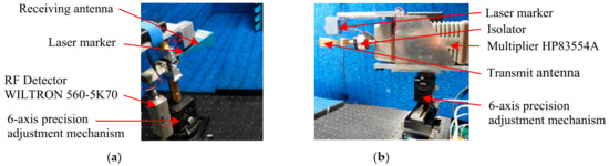
Figure 7.
(a) Receiving antenna and RF Detector; (b) Multiplier and transmitting antenna.
Figure 8 shows the outline of the installation of the antenna and the sample stand.
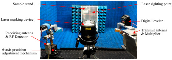
Figure 8.
Outline of the installation of the antenna and sample stand, etc.
The transmitting and receiving horn antennas were installed in a 6-axis precision adjustment mechanism to adjust the height, angle, tilt, etc. These adjustments were made using a laser marking device and a digital level (See Figure 8). The laser marking device used here has a gyro mechanism and automatically draws horizontal and vertical laser beams on the front and both sides. This was used to adjust the installation position and angle of each antenna and the sample stand.
Note: The laser marking device and digital level used for adjustment were removed during measurement, but the laser markers installed on each antenna were operated during measurement to monitor the angle of incidence.
3.3.4. Outline of the Verification System for the Amount of Radio Wave Absorption for the 75 GHz Band
The 75 GHz band verification system used the same equipment as the 28 GHz band, except for the horn antenna, Multiplier, and reception down converter. Figure 9 shows an outline of the installation of a horn antenna for the 75 GHz band, a Multiplier, and a down converter for reception.
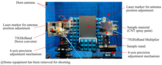
Figure 9.
Outline of the installation of the verification system and sample material for 75 GHz band.
The transmission system generated an RF signal from 74.1 GHz to 75.9 GHz by multiplying the RF signal from 12.35 GHz to 12.65 GHz oscillated from the Sweep Generator by 6 with the Multiplier. The receiving system used a down converter in which a frequency 73 GHz lower than the received frequency is output as an intermediate frequency (IF). By supplying this IF output to the RF Detector, the transmission loss was measured. The down converter used here is a super heterodyne method because it has high sensitivity and is less affected by unnecessary waves.
3.3.5. Sample Stand
The test material stand was made of foamed polypropylene and was installed on an infrared-controlled rotary tape using a 2-axis precision stage to adjust the tilt. After installing the sample material, the installation angle of the sample material stand was finely adjusted by the infrared controller while monitoring the transmission loss (See Figure 10).
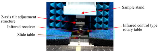
Figure 10.
Sample stand installed on an infrared control type rotary table.
4. Measurement Result of Radio Wave Absorption
4.1. 28 GHz Band Radio Wave Absorption
The sweep generator was set so that the center frequency of the signal output from the transmitting antenna was 28 GHz, and the sweep frequency was from 26.5 GHz to 29.5 GHz.
The marker for the level measurement of the Scalar network analyzer was set to 28 GHz, and the level resolution was set to 10 dB/1 Division. Figure 11, Figure 12, Figure 13 and Figure 14 show a copy of the Scalar network analyzer screen during measurement. Figure 11a is a copy of the measurement screen at the time of calibration. It can be confirmed that the value in the measurement frequency band is linear when nearly at 0 dB. Calibration was performed based on the Japanese Industrial Standard R1679 using a polished aluminum plate. Figure 11b is a screen copy of the calibration and the measurement of only the expanded polypropylene used for the substrate. It can be confirmed that there is no change from the value at the time of calibration even if the foamed polypropylene is installed. This indicates that the expanded polypropylene does not affect the radio wave absorption effect. The decibel value in parentheses indicates the amount of radio wave absorption.
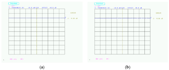
Figure 11.
Changes in the amount of radio wave absorption depending on the board: (a) Calibration (−0.02 dB); (b) Foamed polypropylene (−0.06 dB).
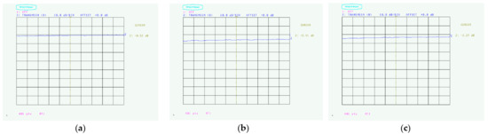
Figure 12.
Radio wave absorption of CNT spray paint: (a) Coating thickness 16 μm (0.52 dB); (b) Coating thickness 35 μm (5.91 dB); (c) Coating thickness 76 μm (3.29 dB).
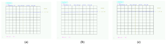
Figure 13.
Radio wave absorption of carbon black paint: (a) Coating thickness 16 μm (3.29 dB); (b) Coating thickness 35 μm (2.32 dB); (c) Coating thickness 76 μm (1.62 dB).
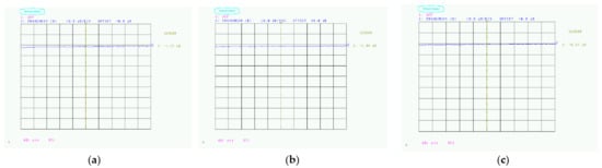
Figure 14.
Radio wave absorption of graphite paints: (a) Coating thickness 15 μm (1.27 dB); (b) Coating thickness 36 μm (1.44 dB); (c) Coating thickness 74 μm (0.57 dB).
Figure 12, Figure 13 and Figure 14 are screen copies of the CNT spray paint, carbon black paint, and graphite paint when the amount of radio wave absorption is measured. The decibel value in parentheses is the amount of radio wave absorption. The value is attenuated by absorbing radio waves from the reference value obtained by the calibration with the sample material. Although the measured value shows a minus, the minus is omitted for the radio wave absorption amount.
It can be seen that the amount of radio wave absorption of the CNT spray paint is the largest, as shown in Figure 12. With CNT spray paint, the amount of radio wave absorption was the largest at 5.91 dB with a coating thickness of 35 μm. Figure 13 shows the amount of radio wave absorption with the carbon black paint. When the coating thickness was 16 μm, a maximum radio wave absorption amount of 3.29 dB was obtained, which is smaller than that of the CNT spray paint. Figure 14 shows the amount of radio wave absorption with the graphite paint. When the coating thickness was 36 μm, a maximum radio wave absorption amount of 1.44 dB was obtained, which is the smallest value among the three carbon materials.
From these facts, it can be seen that the amount of radio wave absorption varies greatly depending on the type of sample material and also the coating thickness.
4.2. 75 GHz Band Radio Wave Absorption
In the 75 GHz band, the Sweep Generator was set so that the signal output from the transmitting antenna had a center frequency of 75 GHz and a sweep frequency of 74.1 GHz to 75.9 GHz. The marker for the level measurement of the Scalar network analyzer was set to 75 GHz, and the level resolution was set to 10 dB/1 Division. Figure 15, Figure 16, Figure 17 and Figure 18 show screen copies of the Scalar network analyzer during measurement.
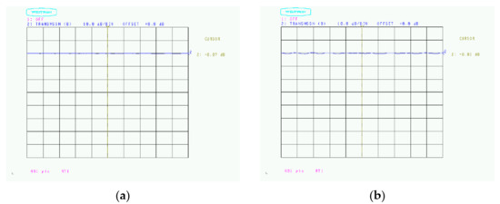
Figure 15.
Changes in the amount of radio wave absorption depending on the board: (a) Calibration (+0.07 dB); (b) Foamed polypropylene (−0.01 dB).
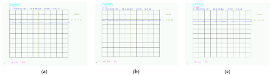
Figure 16.
Radio wave absorption of CNT spray paint: (a) Coating thickness 16 μm lower part (7.14 dB); (b) Coating thickness 35 μm upper part (1.45 dB); (c) Coating thickness 75 μm lower part (3.76 dB).
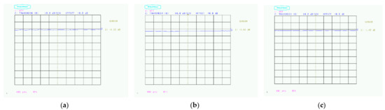
Figure 17.
Radio wave absorption of carbon black paint: (a) Coating thickness 16 μm lower part (1.32 dB); (b) Coating thickness 35 μm upper part (3.03 dB); (c) Coating thickness 75 μm upper part (1.47 dB).
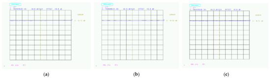
Figure 18.
Radio wave absorption of graphite paint: (a) Coating thickness 15 μm upper part (0.77 dB); (b) Coating thickness 36 μm lower part (0.93 dB); (c) Coating thickness 74 μm upper part (0.71 dB).
Figure 15a is a copy of the measurement screen at the time of calibration. It can be confirmed that the value in the measurement frequency band is linear when nearly 0 dB. The aluminum plate used for calibration is mirror-finished so that the surface unevenness is 1/10 or less (0.4 mm or less) of the wavelength in order to prevent diffused reflection from surface unevenness.
Figure 15b is a screen copy of the calibration and the measurement of only the expanded polypropylene used for the substrate.
In the 75 GHz band, due to the effect of installing the expanded polypropylene, it repeatedly increases/decreases slightly in the 350 MHz cycle. However, since the range of change is as small as about 0.3 dB, it was judged that it would not have a significant effect on the measurement results.
Figure 16 shows the radio wave absorption of CNT spray paint, Figure 17 shows the carbon black paint, and Figure 18 shows the amount of radio wave absorption of graphite paint. Since variations in the measured values were confirmed at the measurement points, measurements were performed at the upper and lower parts of the sample, but the screen copies of Figure 16, Figure 17 and Figure 18 show only the best values.
With CNT spray paint, the amount of radio wave absorption was the largest at 7.14 dB with a coating thickness of 16 μm. This is a little larger than the amount of radio wave absorption in the 28 GHz band (see Figure 16). With carbon black paint, a maximum amount of radio wave absorption of 3.03 dB was obtained when the coating thickness was 35 μm (see Figure 17). In addition, graphite paint showed a maximum amount of radio wave absorption of 0.93 dB when the coating thickness was 36 μm, but there was only a maximum difference of 0.22 dB from the other coating thicknesses, so radio waves can be obtained regardless of the coating thickness. Almost no absorption effect was obtained (see Figure 18).
As mentioned above, even in the 75 GHz band, the amount of radio wave absorption shows the same tendency as in the 28 GHz band, and it can be seen that the amount of radio wave absorption of the CNT spray paint is the largest. In the 28 GHz band, the measurement frequency bandwidth was 3 GHz, but in the 75 GHz band, it was 800 MHz, which is relatively narrow, so the frequency characteristics could not be confirmed (see Figure 16). From these measurement results, it was also found that the amount of radio wave absorption varies greatly depending on the type of test material even if the frequency changes, and also changes depending on the coating thickness. Regarding the coating thickness, it was also found that the optimum thickness changes depending on the frequency.
5. Discussion
5.1. Measurement of 28 GHz Band
Table 1 summarizes the amount of radio wave absorption in the 28 GHz band measured for each coating thickness.

Table 1.
28 GHz band radio wave absorption.
The maximum value of the radio wave absorption in the 28 GHz band was confirmed when 35 μm of CNT spray paint was applied. The carbon black paint obtained a radio wave absorption amount of about 60% of that of the CNT spray paint. It was confirmed that the graphite paint did not have much absorption effect even when the coating thickness was changed.
The amount of radio wave absorption of the CNT spray paint with a coating thickness of 16 μm is smaller than that of other paints, which is considered to be due to the fact that the coating thickness in the vicinity of the irradiation of radio waves is thin. In order to verify this, a part of the coating film of the test material used for the measurement was peeled off, and the coating thickness at the center of the test material was measured. The coating thickness was measured using a KEYENCE double-scan high-precision laser measuring instrument (LT-9500) and a sensor head with a camera function (LT-9010M). Figure 19 and Figure 20 show screen copies during measurement.
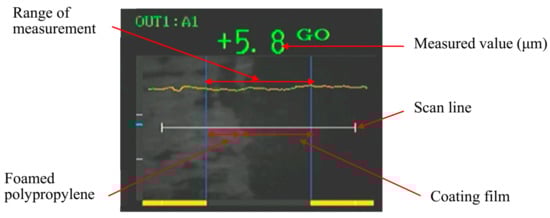
Figure 19.
Screen copy when measuring the thinnest part.
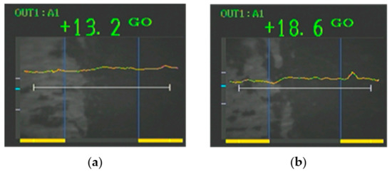
Figure 20.
Coating thickness at the top and bottom of the sample: (a) top 13.2 μm; (b) bottom 18.6 μm.
The black part on the right is the coating film, and the gray part on the left is the part where the coating film is peeled off. The numerical value at the top is the coating thickness at the center of the screen. The coating thickness was about 6–9 μm, and the thinnest part was 5.8 μm. (See Figure 19). In order to confirm the variation in coating thickness, the coating thickness at the top and bottom of the sample was also measured. The coating thickness was about 13–19 μm, and although there was a large variation, it could be seen that the coating was thicker than the central part (see Figure 20).
From this, it was confirmed that the radio wave absorption amount of the CNT spray paint with a coating thickness of 16 μm was lower than that of other carbon-based paints due to the influence of the variation in the coating thickness.
The difference in the amount of radio wave absorption depending on the coating thickness was observed in all the test materials, but it could be seen that the appropriate coating thickness differed depending on the material. In addition, when the coating thickness was 76 μm, the amount of radio wave absorption decreased in all the test materials. It is considered that this is because the amount of radio wave absorption decreased due to the increase in the amount of reflection.
The shape of CNTs tends to be elongated and difficult to spray compared to carbon grains and graphite grains. The coating sample used this time was prepared by Fukoku Co., Ltd., but it seems that there is a problem with the shape of their spray head, and it is presumed that this led to the above results being obtained. Next time, it will be necessary to reconfirm with a spray [24,25,26,27] that applies a nozzle developed by Chiba and Waki. This spray system has been developed to make it easier to create electrodes for dielectric elastomers [32,33]. The dielectric elastomer developed by Chiba and Waki uses this system to disperse the SWCNTs more evenly, resulting in a uniform thickness. It has become possible to show growth. In addition to the above, it is considered that a higher radio wave absorption effect can be obtained by realizing a CNT spray paint specializing in the radio wave absorption effect by adjusting the CNT dispersion conditions, the types of binders, the compounding ratios, etc. Furthermore, in order to reduce the cost, it is considered that the shielding characteristics can be controlled by adding another carbon-based material or changing the coating thicknesses. As another improvement method, a method of devising a three-dimensional structure, such as laminating the same components as the sample material, can be considered. Alternatively, a porous material can be used as the base material to be applied, and an effervescent material can be added to the binder of the CNT spray paint. Then, it seems that a three-dimensional structure will be possible without stacking, and it will be possible to improve the radio wave absorption effect more simply. Currently, it is being verified that the reflected wave can be reduced and the radio wave absorption effect can be improved by combining the CNT spray coating film and the space in the radio wave propagation path.
As a trial test, in order to simply verify the idea above, we created a sample using our CNT spray method and a highly foamable polypropylene with a thickness of 3 mm. The coating thickness at the measurement point was about 18 μm. Figure 21 shows a screen copy during measurement.
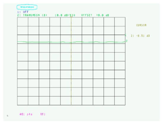
Figure 21.
Radio wave absorption of sample material created by our CNT spray method (8.51 dB).
Even with a small amount of coating, the amount of radio wave absorption was improved by about 2.5 dB.
5.2. 75 GHz Band Measurement
Table 2 summarizes the amount of radio wave absorption in the 75 GHz band measured for each coating thickness.
Table 2.
Radio wave absorption in the 75 GHz band.
Since variations in the measured values were confirmed depending on the measurement points, the measurement points were set at two points, the upper part and the lower part, with the center as the boundary, and the average value was calculated.
The maximum value of radio wave absorption in the 75 GHz band was confirmed when 16 μm of CNT spray paint was applied. It can be seen that the effect of the coating thickness is that the radio wave absorption amount decreases when the coating thickness is 35 μm and increases again when the coating thickness is 76 μm (See Table 2). It is presumed that this is because the coating conditions did not match the CNT spray paint, causing irregularities on the coated surface and diffusing the radio waves, resulting in an increase in the apparent amount of radio waves absorbed. Figure 22 shows the surface photographs of the sample coated with 16 μm of CNT spray paint and the sample coated with 76 μm.
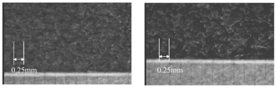
Figure 22.
Surface photograph of the sample material coated with CNT spray paint (magnification: 100 times).
In the sample material with a coating thickness of 15 μm, a slightly darker-colored part (the dented part) of about 0.25 mm can be confirmed, but in the sample material with a coating thickness of 76 μm, parts of about 1 mm are scattered. In addition, the light-colored part (convex part) can be confirmed more clearly. The JIS R1679 recommends that the surface roughness of the sample material be 1/10 or less of the free space wavelength. Since the free space wavelength of 75 GHz is 4 mm, the surface roughness of the sample must be 0.4 mm or less. In the sample material with a coating thickness of 76 μm, a part with a surface roughness of about 1 mm was confirmed. It is considered that radio waves were diffused due to this unevenness. These cases will also be reconfirmed using the spray nozzle developed by Chiba and Waki. The radio wave absorption of other test materials also showed the same tendency as 28 GHz, and the result was that the radio wave absorption effect could not be obtained with graphite paint. It was confirmed that the difference in the amount of radio wave absorption depending on the coating thickness is different from that in the 28 GHz band at the peak point. However, it also changes depending on the coating thickness.
6. Conclusions
It was not possible to confirm the practical effects of carbon black and graphite as radio wave absorbers. On the other hand, in the spray paint using SWCNT, a radio wave absorption effect of 5.91 dB was obtained in the 28 GHz band and when the coating thickness was 35 μm. In the 75 GHz band, a radio wave absorption effect of 6.96 dB was obtained when the coating thickness was 16 μm. However, the sample material used at the beginning showed a slightly lower value in the radio wave absorption in the 28 GHz band because the coating method was not appropriate. Therefore, by preparing a new uniformly coated test material and remeasuring it, we were able to obtain a radio wave absorption effect of 8.51 dB even in the 28 GHz band with a coating thickness of 18 μm.
As described above, the CNT spray paint is effective in a very thin coating film, displaying a large amount of radio wave absorption in the millimeter wave band and at a coating thickness of 18 μm or less. Even if the same paint is used, it is possible to suppress the radio wave absorption effect by changing the thickness of the coating. This shows that CNT spray paint is highly practical as a radio wave absorber in millimeter waves.
In the future, by adjusting each parameter of CNT spray paint, we would like to develop a radio wave absorber that suits the purpose and contributes to the improvement of the worsening electromagnetic wave environment.
Author Contributions
S.C. and M.W. jointly made this measurement and wrote this paper together. All authors have read and agreed to the published version of the manuscript.
Funding
No one has funded this study. Chiba used his own fund.
Institutional Review Board Statement
Not applicable.
Informed Consent Statement
Not applicable.
Data Availability Statement
All data have not been reported yet.
Acknowledgments
We would like to thank ZEON Corporation for providing SWCNTs (ZEONANO®-SG101) free of charge for carrying out the experiment. We would also like to thank Fukoku Co., Ltd. for spraying various carbon-based materials on the samples.
Conflicts of Interest
The authors declare no conflict of interest.
References
- What is Millimeter-Wave Radar that Expands the Possibilities of Autonomous Driving and Industrial Machinery. Available online: https://www.hitachi-solutions-create.co.jp (accessed on 2 November 2021).
- Roudbari, M.; Jorshari, T.; Lü, C.; Ansari; Kouzani, A.; Amabili, M. A review of size-dependent continuum mechanics models for micro- and nano-structures. Thin-Walled Struct. 2022, 170, 108562. [Google Scholar] [CrossRef]
- Chiba, S.; Waki, M.; Takeshita, M.; Uejima, M.; Arakawa, K. Dielectric elastomer using CNT as an electrode. Int. Soc. Opt. Photonics 2020, 11375, 113751C. [Google Scholar] [CrossRef]
- Zhang, H.; Gao, C.; Li, H.; Pang, F.; Zou, T.; Wang, H.; Wang, N. Analysis of functionally graded carbon nanotube-reinforced composite structures. Nanotechnol. Rev. 2020, 9, 1408–1426. [Google Scholar] [CrossRef]
- Nurazzi, N.M.; Asyraf, M.R.M.; Khalina, A.; Abdullah, N.; Sabaruddin, F.A.; Kamarudin, S.; Ahmado, S.H.; Mahat, A.M.; Lee, C.L.; Aisyah, H.A.; et al. Fabrication, functionalization, and application of carbon nanotube-reinforced polymer composite: An overview. Polymers 2021, 13, 1047. [Google Scholar] [CrossRef] [PubMed]
- Ministry of Internal Affairs and Communications. Main Applications and Radio Wave Characteristics for Each Frequency Band. Available online: https://www.tele.soumu.go.jp›freq›myuse›summary (accessed on 2 November 2021).
- Ministry of Environment. About Electromagnetic Field around Us. Available online: http://www.env.go.jp/chemi/electric/mate-rial/minomawari.pdf (accessed on 2 November 2021).
- Association of Radio Industries and Business. Radio Waves in Daily Life. Available online: http://www.arib-emf.org›denpa01-01 (accessed on 2 November 2021).
- First Electronic Development Co., Ltd. Do Electromagnetic Waves Affect the Human Body? Available online: https://www.first-ele.co.jp/den-ziha.html (accessed on 2 November 2021).
- Otsu, A. EMI Noise Problems and Regulations. J. Surf. Finish. Soc. Jpn. 1991, 42, 2–12. [Google Scholar] [CrossRef]
- Hashimoto, O. Radio wave propagation and wave absorption technology in 5G. Eng. Mater. 2021, 69, 18–20. [Google Scholar]
- Sugiyama, A.; Yoshino, M. Plating for Electro-magnetic Shielding. J. Surf. Finish. Soc. Jpn. 2017, 68, 191–195. [Google Scholar] [CrossRef][Green Version]
- Yamamoto, S.; Hatakeyama, K. Design and evaluation of radio wave absorbers and electromagnetic shielding materials that use artificial materials. In Proceedings of the BI-4-1 (The Society Conference) Institute of Electronics Information and Communication Engineers (IEICE), Tokyo, Japan, 11 September 2019. [Google Scholar]
- Zhao, B.; Zhang, R. Electromagnetic Wave Absorption Properties of Core-Shell Ni-Based Composites. In Electromagnetic Materials and Devices; IntechOpen: London, UK, 2018. [Google Scholar] [CrossRef]
- Hayashi, O. Latest Developments in Electromagnetic Wave Absorbers and Shielding Materials-Design and Performance Enhancement for 5G; CMC Publishing Co.: Tokyo, Japan, 2020; pp. 1–318. ISBN 978-4-7813-1513-3. [Google Scholar]
- Koyo Sangyo Co. Ltd. Thickness and Weight Reduction That Could Not Be Achieved with Conventional Radio Wave Absorbers. Available online: https://premium.ipros.jp/koyoweb/catalog/detail/505729/ (accessed on 2 November 2021).
- Kashihara, K.; Fujita, N.; Hashimoto, H.; Ijiri, Y.; Hosono, K.; Mitsui, T.; Kudo, T. Development of the Sheet-Type Electromagnetic Wave Absorber for ETC/DSRC. Mitsubishi Cable Ind. Rev. 2002, 99, 69–77. Available online: https://www.mitsubishi-cable.co.jp/jihou/pdf/95/01.pdf (accessed on 2 November 2021).
- Ishino, K.; Watanabe, T.; Hashimoto, Y. Radio wave absorbers and those applications. Jpn. Soc. Appl. Phys. 1974, 43, 1157–1163. [Google Scholar]
- Toyo Ink SC Holdings. Millimeter-Wave Radio Wave Absorption Compound that Can Be Injection-Molded for in-Vehicle Radar Housing. Available online: https://newswitch.jp/p/27163#:~:te (accessed on 2 November 2021).
- Japan Radio Absorber Co., Ltd. Millimeter Wave Noise Absorption Sheet (CPE/silicon). Available online: https://mwa.co.jp/product/adas/ (accessed on 2 November 2021).
- Sekisui Chemical Co., Ltd. Radio Wave Absorption Sheet (ADAS). Available online: https://www.sekisui-automotive.com›adas.html (accessed on 2 November 2021).
- Maxell Co. Ltd. Electromagnetic Wave Absorption Rubber Sheets. Available online: https://biz.maxell.com/ja/adhesive_tapes_inks_functional_films/electromagnetic_wave_suppression_sheet2.html (accessed on 2 November 2021).
- Kansai Paint, Co. Ltd. For Millimeter Waves for the Purpose of Preventing Automatic Driving Malfunction. Available online: https://www.kansai.co.jp›sites›files›new›press18 (accessed on 2 November 2021).
- Chiba, S. Super flexible electrode for a DE made with CNT spray. In Proceedings of the SPIE 11375, Electroactive Polymer Actuators and Devices (EAPAD) XXII, Anaheim, CA, USA, 22 April–9 May 2020. [Google Scholar] [CrossRef]
- Chiba, S.; Waki, M.; Takeshita, M.; Yoshizawa, T. Improvement Measurement for Dielectric Elastomers for Heavy Duty Uses Such as Robots and Power assist Devices. Adv. Theor. Comput. Phys. 2021, 4, 241. [Google Scholar] [CrossRef]
- Chiba, S.; Waki, M.; Takeshita, M.; Uejima, M.; Arakawa, K. Single-wall CNT spray for easy creation of DE electrodes (Conference Presentation). In Proceedings of the SPIE 11375, Electroactive Polymer Actuators and Devices (EAPAD) XXII, Anaheim, CA, USA, 22 April–9 May 2020. [Google Scholar] [CrossRef]
- Chiba, S.; Waki, M.; Takeshita, M.; Uejima, M.; Arakawa, H.; Ohyama, K.; Yoshizawa, T.; Yoshizawa, S.; Yoshizawa, Y. Electromagnetic Wave Leakage Absorption Film Using CNT Spray. In Proceedings of the SPIE 11745, Passive and Active Millimeter-Wave Imaging XXIV, online, 12–17 April 2021. [Google Scholar] [CrossRef]
- Tenent, R.; Barnes, T.; Bergeson, J.; Ferguson, A.; To, B.; Gedvilas, L.; Heben, M.; Blackburn, J. Ultrasmooth, Large-Area, High-Uniformity, Conductive Transparent Single-Wall-Carbon-Nanotube Films for Photovoltaics Produced by Ultrasonic Spraying. Adv. Mater. 2009, 21, 3210–3216. [Google Scholar] [CrossRef]
- Chen, Z.; Qiao, N.; Yang, Y.; Ye, H.; Liu, S.; Wang, W.; Wang, Y. Enhanced Broadband Electromagnetic Absorption in Silicon Film with Photonic Crystal Surface and Random Gold Grooves Reflector. Sci. Rep. 2015, 5, 12794. [Google Scholar] [CrossRef] [PubMed]
- The Japanese Industrial Standards Committee (JISC). Japanese Industrial Standards (JIS) Search Site. Available online: https://www.jisc.go.jp/app/jis/general/GnrJISSearch.html (accessed on 2 November 2021).
- Fukoku Co. Ltd. Available online: http://www.fukoku-rubber.co.jp/ (accessed on 2 November 2021).
- Chiba, S.; Waki, M.; Ono, K.; Hatano, R.; Taniyama, Y.; Tanaka, S.; Okada, E.; Ohyama, K. Challenge of creating high performance dielectric elastomers. In Proceedings of the SPIE2021 (Smart Structures and Materials Symposium and its 23rd Electroactive Polymer Actuators and Devices (EAPAD) Conference), Anaheim, CA, USA, 22–27 March 2021; pp. 1157–1162. [Google Scholar] [CrossRef]
- Chiba, S. Development and application of dielectric elastomers (0.15g DE can lift 8 kg weight). Funct. Mater. 2021, 41, 33–39. [Google Scholar]
Publisher’s Note: MDPI stays neutral with regard to jurisdictional claims in published maps and institutional affiliations. |
© 2021 by the authors. Licensee MDPI, Basel, Switzerland. This article is an open access article distributed under the terms and conditions of the Creative Commons Attribution (CC BY) license (https://creativecommons.org/licenses/by/4.0/).