
Common-Ground Photovoltaic Inverters for Leakage Current Mitigation: Comparative Review

 , ,
, , 

Abstract
:1. Introduction
- Undesirable tripping of residual current protection system;
- Deterioration of electromagnetic compatibility (EMC);
- Decreasing of PV modules lifetime;
- Harmonic distortion of the current injected into the grid;
- An electric shock for persons touching the PV module.
- It can eliminate the injection of DC current into the grid. Such DC current might result in saturation of the distribution transformers and electric motors along over the grid [12,13]. In addition, it can degrade power cables over time and affect normal load operation [14,15]. DC current injection may result due to several factors, such as asymmetric operation during positive and negative half-cycles, delays in gate drive circuits, and offset drift in the current sensing [14,15];
- -
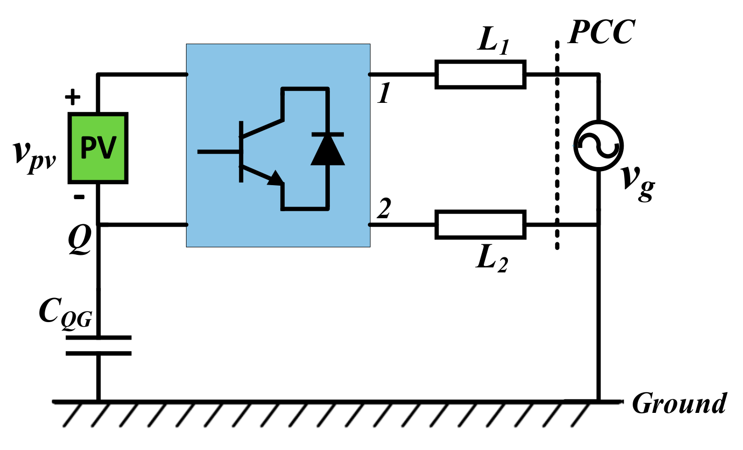
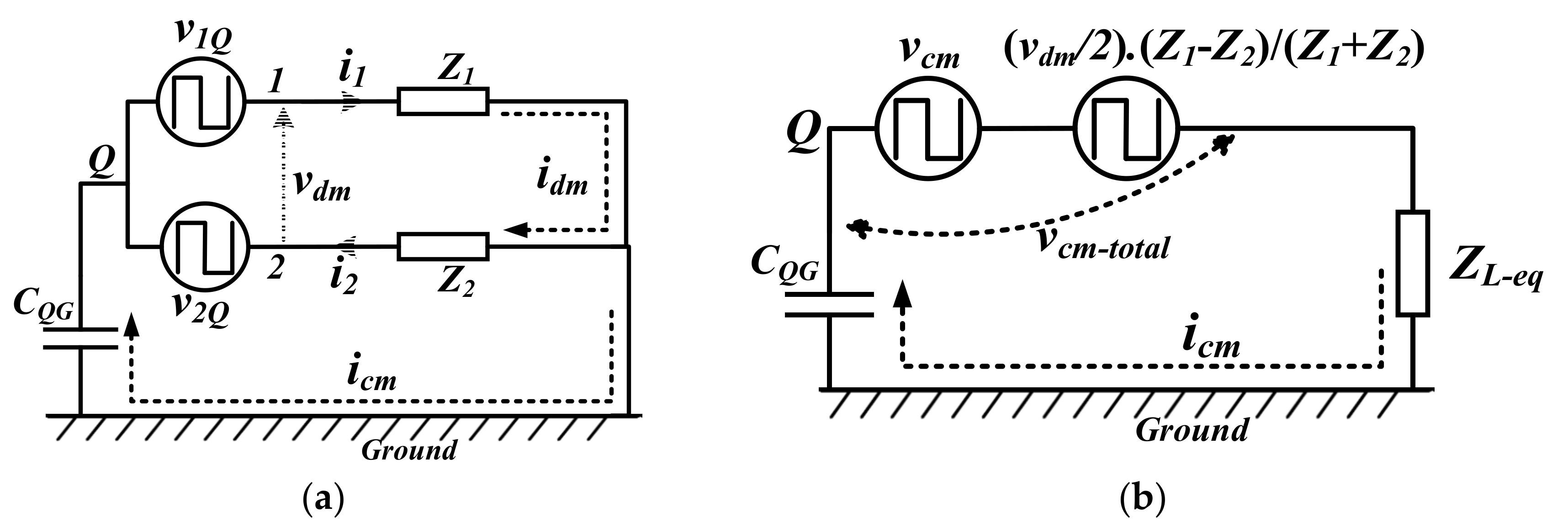
- Generation mechanism of leakage current
- -
- Mitigation methods of leakage current
- Using of common-mode (CM) chokes: this represents an effective solution to mitigate the leakage current in grid-connected systems [21]. These filters can be connected on either the DC side or the AC side of the inverter. To reduce the required size and weight, a number of configurations have been proposed for magnetic integration of the differential-mode (DM) and common-mode (CM) filters [22]. In these configurations, two types of coils use a common core; according to the DM and CM current directions, some coils attenuate the DM current component, and the other coils attenuate the CM current components. However, these filters introduce a significant increase in cost, size, and weight. In addition, the losses of these coils reduce the overall efficiency. Furthermore, core saturation at high leakage current values worse the overall system performance. Thus, large cores might be needed to avoid such scenario;
- Keeping constant CMV: Accordingly, no leakage current can be generated. According to the expression in (3), two conditions must be realized for this purpose:
- (1)
- Equal line impedances (Z1 and Z2). This requires two filter inductors with independent iron cores, which can result in increased size and cost.
- (2)
- Achieving constant value for CM component expressed in (1). Some effort has been reported in the literature to achieve constant CM component; two main directions are followed:
- a.
- Modulation-based method [1,3,4,6,8]. A simple way to realize the constant CM component is to use the full-bridge inverter with the bipolar sinusoidal PWM; this offers a constant CM at half of the DC bus voltage. However, compared to unipolar sinusoidal PWM, such modulation strategy results in high switching losses and high harmonic contents, which need a large filter size.
- b.
- Converter-based methods (modified full-bridge converters). To keep constant CM when the unipolar modulation is used, a number of topologies have been developed based on the full-bridge inverter, such as the H5 inverter and the HERIC inverter. The main idea of these topologies is the disconnection of PV from the grid during freewheeling mode. This is achieved through inserting extra switches into the full-bridge inverter either on the dc or ac side [9,23,24,25]. However, this will need extra switches, which increases the cost. In addition, perfect disconnection cannot be realized because of the switch parasitic capacitance [26].
- Bypassing the parasitic capacitance of PV through using common-ground converters. This represents the most effective solution as it offers complete mitigation of the leakage current by providing a solid connection between the negative terminal photovoltaic modules and the neutral of the grid side. In addition, the grounding of a PV system can minimize the effects of lighting and other surges [27].
2. Classification of Common-Ground Converters
- -
- Current-source CG converters (CSCG);
- -
- Voltage-source CG converters (VSCG); this category can be further classified as follow:
- (a)
- Bucking VSCG;
- (b)
- Boosting VSCG;
- (c)
- Buck/boost VSCG.
- -
- Number of semiconductors (switches and diodes) and number of passive components (capacitors and inductors) along with their values adopted in the reported experimental results of each converter: this can imply the size, cost, complexity, and efficiency of these converters;
- -
- -
- Input/output voltage gain (for VSCS converters): high boosting gain is an important feature in PV converters. This can significantly reduce the capacitance required for power decoupling; in addition, this reduces the required number of series-connected PV modules for grid-tied systems;
- -
- -
- -
- The reported efficiency for each converter: this implies the total losses for each converter; these losses can be varied according to the converters’ structure and switching mechanism.

| Topology | Total No. of Components (S: Switches, D: Diodes, C: Capacitors, L: Inductors) | No. of Semiconductors in Current Path | Output Voltage Levels | Voltage Gain | Is Input Current Continous? | Reported Efficiency | |||||||
|---|---|---|---|---|---|---|---|---|---|---|---|---|---|
| Type | Refs. No. | S | D | C (Capacitance) | L (Inductance) | +Half Cycle | -Half Cycle | ||||||
| Current-sourceCG inverters | [36,37] | 4 | 0 | 2 (3 and 2200 uF) | 2 (0.25 and 0.5 mH) | 2 | 2 | - | Yes | 95.7% @300 W | |||
| [38] | 5 | 0 | 1 (220 uF) | 1 (0.3 mH) | 2 | 2 | - | NR | No | 92.5% @200 W | |||
| [39] | 5 | 3 | 1 (NR) | 1 (320 uH) | 4 | 3 | - | NR | No | NR | |||
| [40] * | 4 | 0 | 2 (NR) | 1 + 1 (coupled) (NR) | 2 | 2 | - | Yes | NR | ||||
| [41] | 3 | 0 | 2 (2 × 18.8 uF) | 3 (675 uH and 2 × 1 mH) | 2 | 2 | - | Yes | ≈92.2% @200 W | ||||
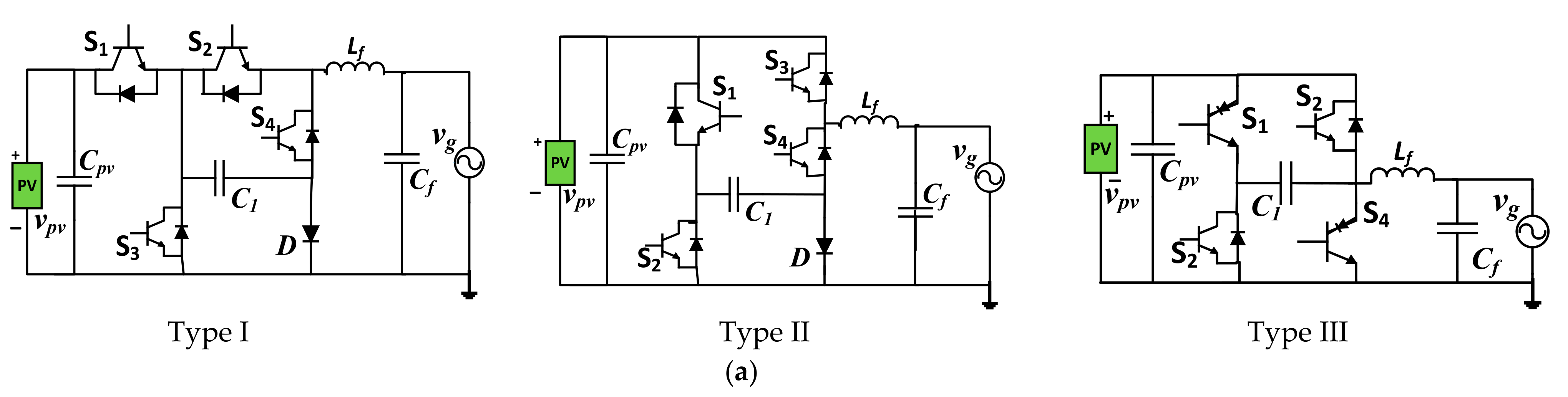
| Voltage-source CG inverters | Buck | [42,43,44] | I | 4 | 1 | 2 (NR and 470 uF) | 0 | 2 | 2 | 3 | M | No | 99.2 @1 kW |
| II | 4 | 1 | 2 (NR and 470 uF) | 0 | 1 | 2 | 3 | No | 99.25 @1 kW | ||||
| III | 4 | 0 | 2 (NR and 650 uF) | 0 | 1 | 1 | 3 | No | 97.8 @1 kW | ||||
| [45] | 4 | 0 | 2 (NR and 45 uF) | 1 (230 uH) | 2 | 2 | 2 | M | No | 96.1% @3 kW | |||
| [46] | 4 | 2 | 3 (470 and 330 and 220 uF) | 0 | 2 | 2 | 3 | M | No | 97.4% @500 W | |||
| [47] | 5 | 0 | 2 (470 and 940 uF) | 0 | 3 | 2 | 3 | M | No | ≈97% @500 W | |||
| [48] | 4 | 0 | 2 (NR and 1.1 mF) | 0 | 2 | 2 | 3 | M (≤0.637) | No | 97.04% @1 kW | |||
| [49] | 5 | 0 | 2 (100 and 400 uF) | 0 | 3 | 3 | 3 | M | No | ≈97% @1 kW | |||
| [50] | 2 | 0 | 2 (250 and 110 uF) | 1 (2 mH) | 1 | 1 | 2 | NR | Yes | ≈96% @200 W | |||
| [51] | 8 | 0 | 3 (3 × 1 mF) | 0 | 2/2 | 3/2 | 5 | M | No | ≈97.1% @800 W | |||
| [52] | 6 | 1 | 3 (2 × 0.5 mF and 2 mF) | 0 | 3/2 | 3/3 | 5 | M | No | ≈95% @1.2 kW | |||
| [53] | 7 | 0 | 3 (1 and 2 × 2 mF) | 0 | 2/3 | 3/3 | 5 | M (≤0.637) | No | ≈97.5% @500 W | |||
| Boost | [54] | 7 | 3 | 5 (4 × 4.7 and 32 uF) | 4 (3 × 180 uH and 205 uH) | 2 | 2 | 3 | Yes | ≈94.43% @300 W | |||
| [55] * | 6 | 2 | 3 | 2 | 2 | 2 | 3 | yes | NR | ||||
| [56] * | 6 | 5 | 3 | 1 (coupled) | 3 | 3 | 3 | Yes | NR | ||||
| [57] | 4 | 1 | 2 (2 × 1 m F) | 1 (1 mH) | 2 | 2 | 3 | Yes | NR | ||||
| [58,59] | 5 | 0 | 1 (47 uF) | 1 (0.2 mH) | 3 | 2 | 3 | Yes | ≈95.5% @440 W | ||||
| [60] | 3 | 5 | 6 (100 and 20 and 2 × 10 and2 × 120 uF) | 1 + 1 (coupled)(600 and 220 uH) | 1 | 1 | 2 | Yes | ≈92.5% @200 W | ||||
| [61] | 3 | 0 | 3 (3 × 100 uF) | 1 + 1 (coupled)(240 and 60 uH) | 1 | 1 | 2 | Yes | ≈90.5% @280 W | ||||
| [62] | 6 | 2 | 3 (NR and 120 and 680 uF) | 0 | 2/3 | 3/2 | 5 | 1+M | Yes | ≈98.1% @900 W | |||
| [63] | 10 | 0 | 2 (0.94 and 0.47 mF) | 1 (100 uH) | 3/2 | 3/2 | 5 | Yes | ≈98.2% @1 kW | ||||
| Buck/boost | [64] * | 5 | 0 | 2 (NR and 47 uF) | 1 (110 uH) | 3 | 3 | 3 | Yes | NR | |||
| [65] | 7 | 1 | 3 (3 × 10 uF) | 0 | 2 | 1 | 3 | 2M | Yes | ≈98.1% @500 W | |||
| [66] | 2 | 0 | 1 (1 uF) | 2 (2 × 1.3 mH) | 1 | 1 | 2 | Yes | ≈93.5% @200 W | ||||
| [67,68] | 6 | 2 | 2 (0.47 and 1 mF) | 0 | 3/3 | 3/2 | 5 | 2M | Yes | ≈98.1% @600 W | |||
| [69] | 6 | 0 | 1 (47 uF) | 1 (110 uH) | 2 | 3 | 3 | NR | Yes | NR@250 W | |||
| [70,71] | 5 | 0 | 2 (11 uF and2.2 mF) | 1 (52 uH) | 2 | 3 | 3 | Yes | ≈93.5% @300 W | ||||
| [72] | 5 | 2 | 2 (NR and 46 uF) | 1 (110 uH) | 3 | 4 | 3 | Yes | NR | ||||
| [73] | 5 | 1 | 2 (NR and 50 uF) | 1 (110 uH) | 2 | 2 | 3 | No | NR @300 W | ||||
| [74] | 6 | 0 | 2 (NR and 47 uF) | 1 (110 uH) | 2 | 3 | 3 | NR | Yes | NR | |||
| [75] | 5 | 4 | 2 (2 × 1.36 mF) | 1 (3 mH) | 4 | 2 | 3 | yes | NR @500 W | ||||
| [76,77,78] | 9 | 0 | 2 (2 × 1.64 mF) | 0 | 3/4 | 3/4 | 5 | 2M | No | ≈98.5% @1 kVA | |||
| [79] | 9 | 2 | 3 (2 × 0.47 and 1 mF) | 0 | 2/2 | 2/2 | 5 | 2M | No | ≈96.5% @600 W | |||
| [80] | 7 | 0 | 2 (2 × 1 mF) | 1 (3 mH) | 3/3 | 3/4 | 5 | Yes | NR | ||||
| [81] | 8 | 0 | 3 (NR) | 0 | 3/3 | 3/3 | 4 | (3/2) M | Yes | NR | |||
| [82] | 4 | 0 | 1 (100 uF) | 1 (3 mH) | 2 | 2 | 3 | Yes | ≈96.5% @2 kW | ||||
| [83] | 5 | 4 | 2 (NR and 2 × 6.8 uF) | 3 (1 mH and 2 × 30 uH) | 2 | 3 | 3 | Yes | ≈96.5% @400 W | ||||
2.1. Current-Source CG Converters (CSCG)
- ▪
- ▪
- Compared to other converters in this category, the converters introduced in [38,39] cannot offer continuous input current; thus, inefficient MPPT operation is highly expected. For the converter in [39], it also needs the highest number of semiconductors among all CSCG converters; this results in decreased efficiency and cost increase. Furthermore, this converter does not offer a symmetrical current path during positive and negative half-cycles; therefore, it may produce DC current component;
- ▪
- Except for the converter presented in [38], the other converters of this category support bidirectional power flow. Therefore, they can be operated over a wide range of power factors;
- ▪
2.2. Voltage-Source CG Converters (VSCG)
2.2.1. Bucking VSCG
- ▪
- Due to the bucking operation of these converters, a series connection of several PV modules must be used for grid integration. In addition, high capacitance must be adopted for power decoupling purposes;
- ▪
- Except for the topology introduced in [50], all other converters in this category do not offer continuous input current. Therefore, improper MPPT operation is expected;
- ▪
- To overcome the above issues, a front-end DC-DC converter is usually used with bucking VSCG converters. However, this results in increased cost and size;
- ▪
- Among these topologies, the converters introduced in [51,52,53] can offer five voltage levels at the output. Thus, a reduced filter size is needed. On the other hand, the inverters introduced in [45,50] can only offer two voltage levels. Therefore, large filter size is needed. Such high filtering requirements can significantly diminish other features related to the use of a low number of components. All other inverters belonging to this category can offer three voltage levels;
- ▪
- Among the inverters offering five voltage levels, the inverter in [52] uses a fewer number of switches than the other inverters introduced in [51,53]. However, extra electrolytic capacitors are needed for these converters (2 capacitors are needed for the converter in [52], three capacitors for the one in [51,53]). In addition, these converters need a pre-charging circuit to charge the voltages on their capacitors;
- ▪
- ▪
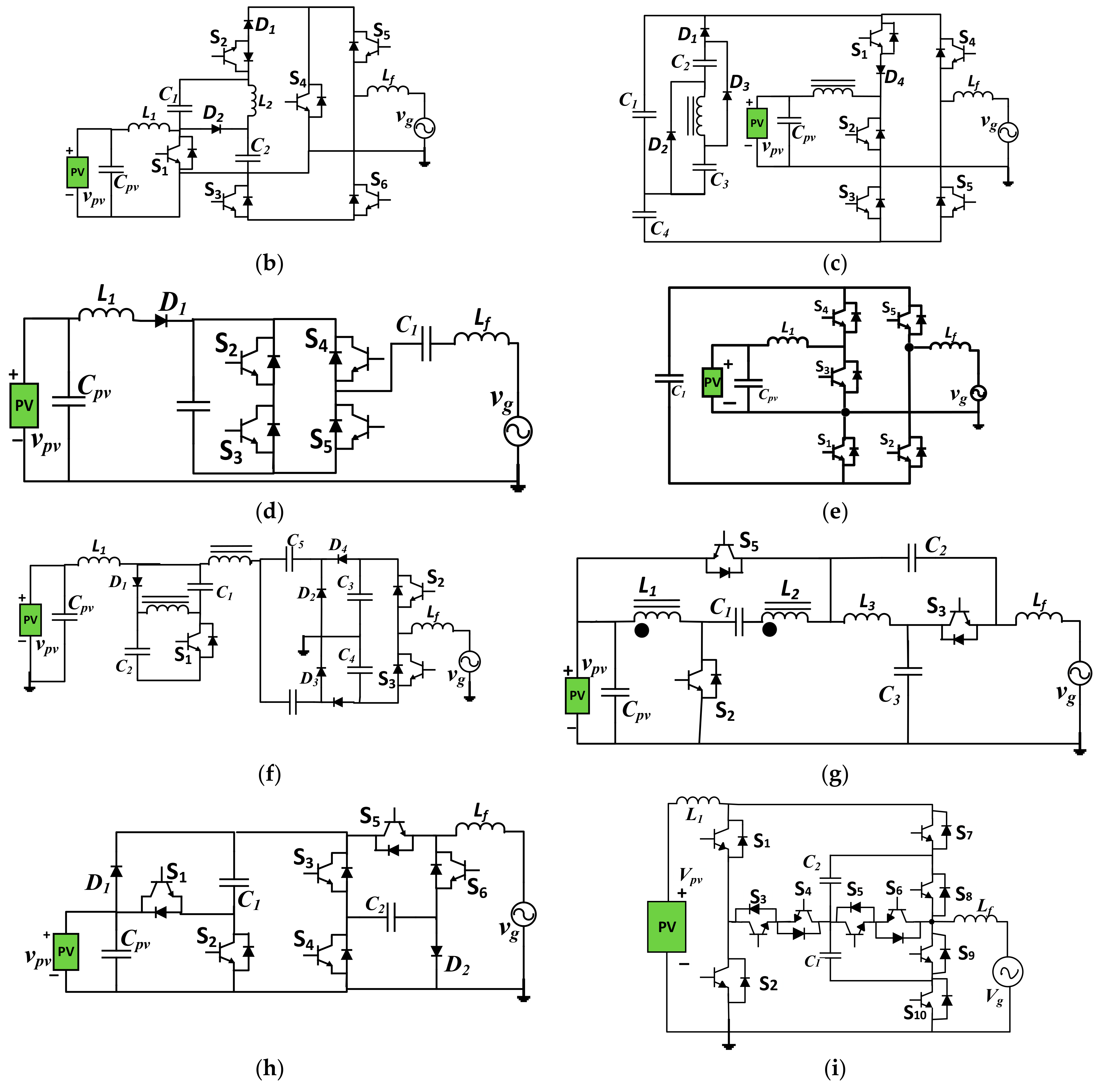
2.2.2. Boosting VSCG
- ▪
- The boosting capability offered by these converters facilitates a reduction in the required decoupling capacitance. This can significantly improve reliability. In addition, all these converters offer continuous input current; this can significantly improve MPPT operation;
- ▪
- The converters introduced in [56,60,61] uses coupled inductors to acquire high boosting capability. However, this results in increased cost and size also. On the other hand, the converters presented in [55,57,62] offer low boosting gain. Finally, the boosting gain offered by other boost converters is high; thus, no series connection of PV modules is needed for grid integration;
- ▪
- Among these topologies, the converters introduced in [62,63] offer five levels at the output voltage. In addition, these converters do not need a pre-charging circuit to charge the voltages on their capacitors. However, high electrolytic capacitors may be needed for voltage balancing over these capacitors. On the other hand, the converters introduced in [60,61] can offer only two voltage levels. Thus, a large filter size is needed. All other inverters belonging to this category can offer three voltage levels;
- ▪
2.2.3. Buck/Boost VSCG
- ▪
- The buck-boost feature offered by these converters makes it applicable for a wide range of power ratings. It can be used with module-integrated PV applications as well as with multi-series-connected PV modules;
- ▪
- Among these converters, those introduced in [76,77,78,79] can offer five voltage levels on their outputs. This can significantly reduce the required filter size. On the other hand, the converter introduced in [66] can offer only two voltage levels. Thus, a large filter size is needed. All other converters belonging to this category can offer three voltage levels;
- ▪
- ▪
- Among these converters, those introduced in [75,83] use a high number of diodes. This reduces efficiency. On the other hand, the converter introduced in [65] uses a high number of switches. This can significantly increase the cost and complexity of operation. These converters need this high number of semiconductors while offering only three voltage levels;
- ▪
- Except for the converter presented in [64], all of these converters support bidirectional power flow; thus, they can be operated at different power factors;
- ▪
- ▪
3. General Discussion
- ○
- Multilevel shaping of output voltage to reduce the filter size;
- ○
- Continuous input current for efficient operation of MPPT;
- ○
- Using the minimum number of semiconductors and passive components to reduce the overall cost, increase the efficiency and decrease the operation complexity;
- ○
- Low DC current generation to follow the related standards;
- ○
- Voltage boosting capability to reduce the required number of series-connected PV modules for grid integration. In addition, this can reduce the capacitance value needed for power decoupling purposes.
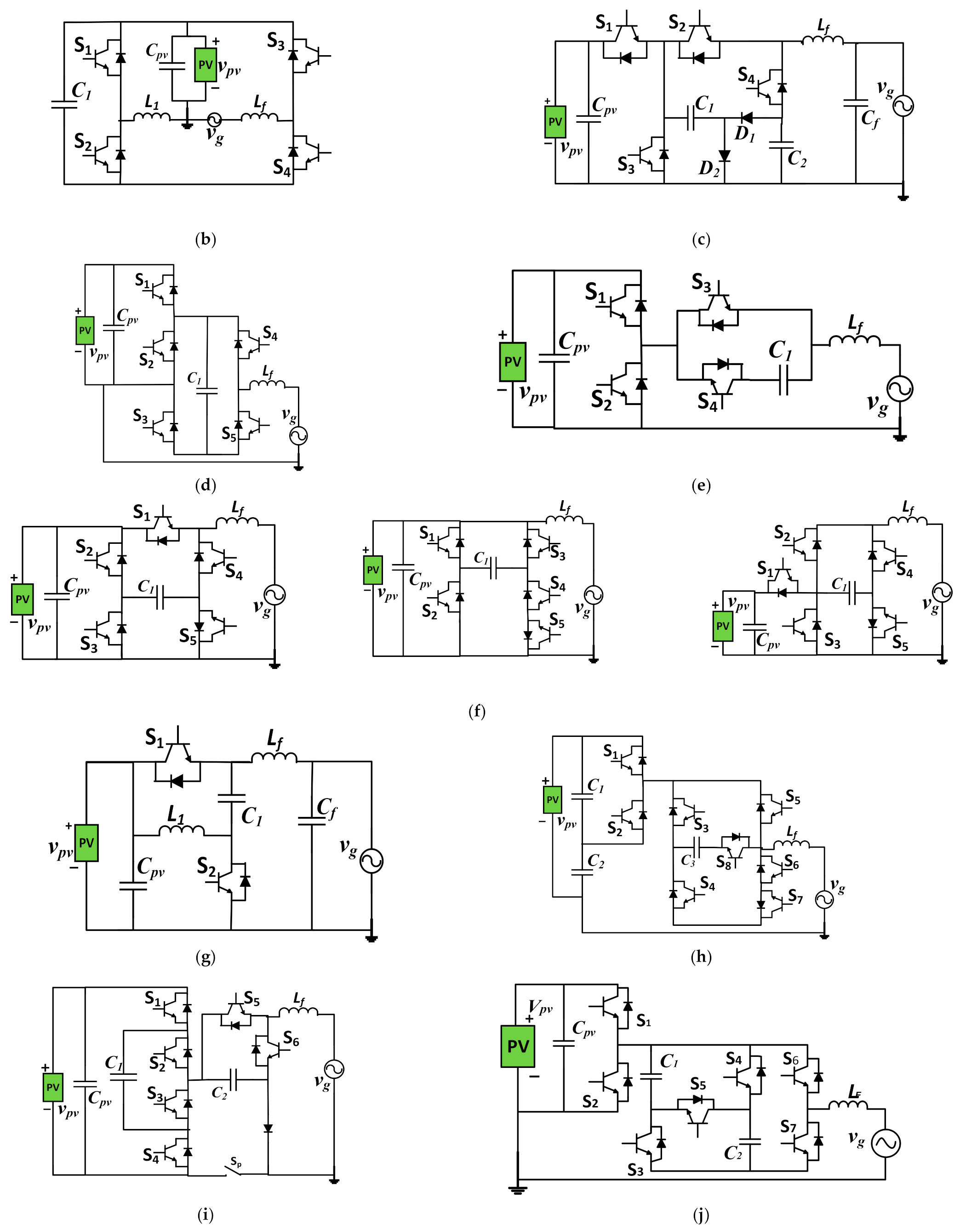
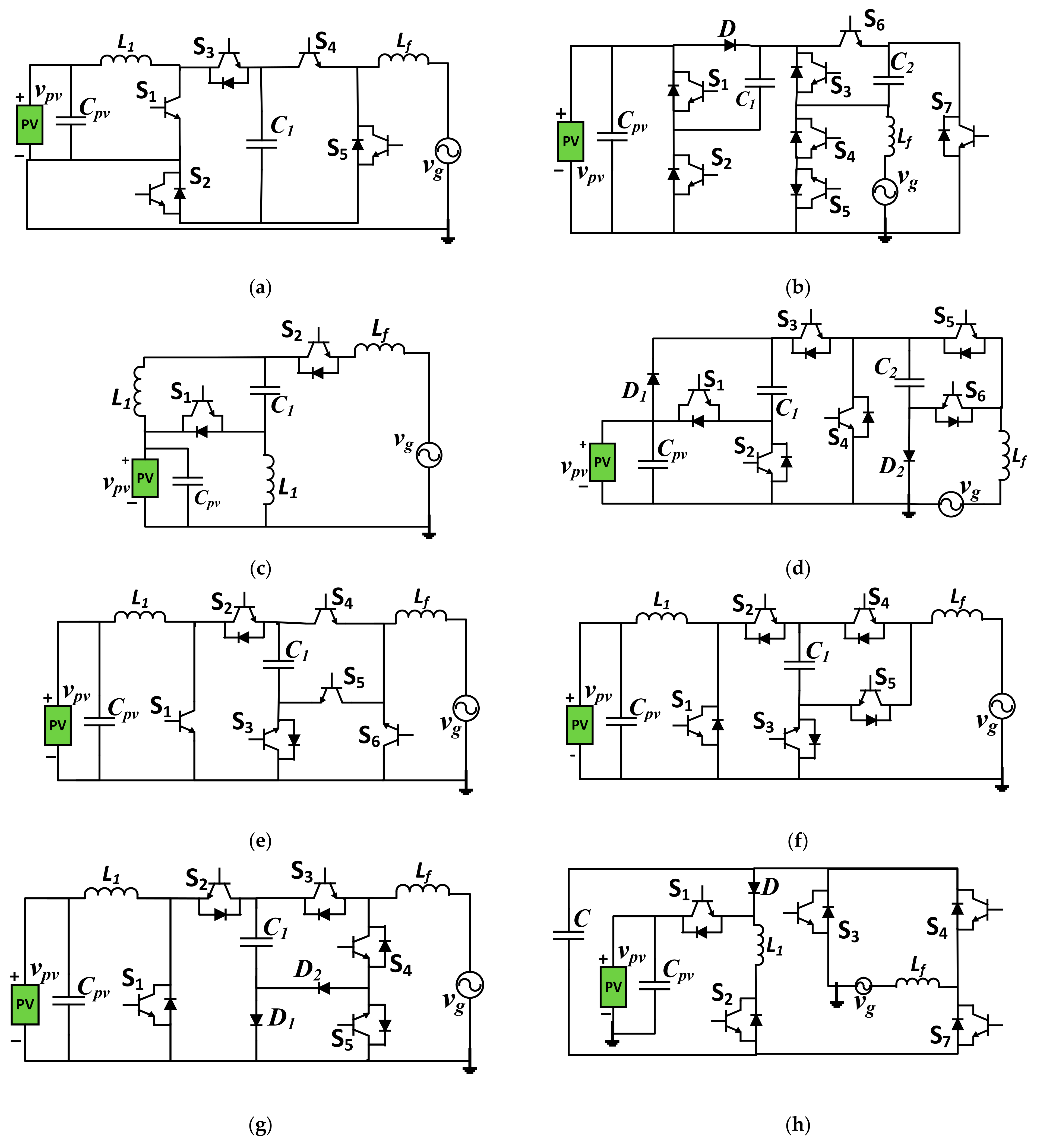
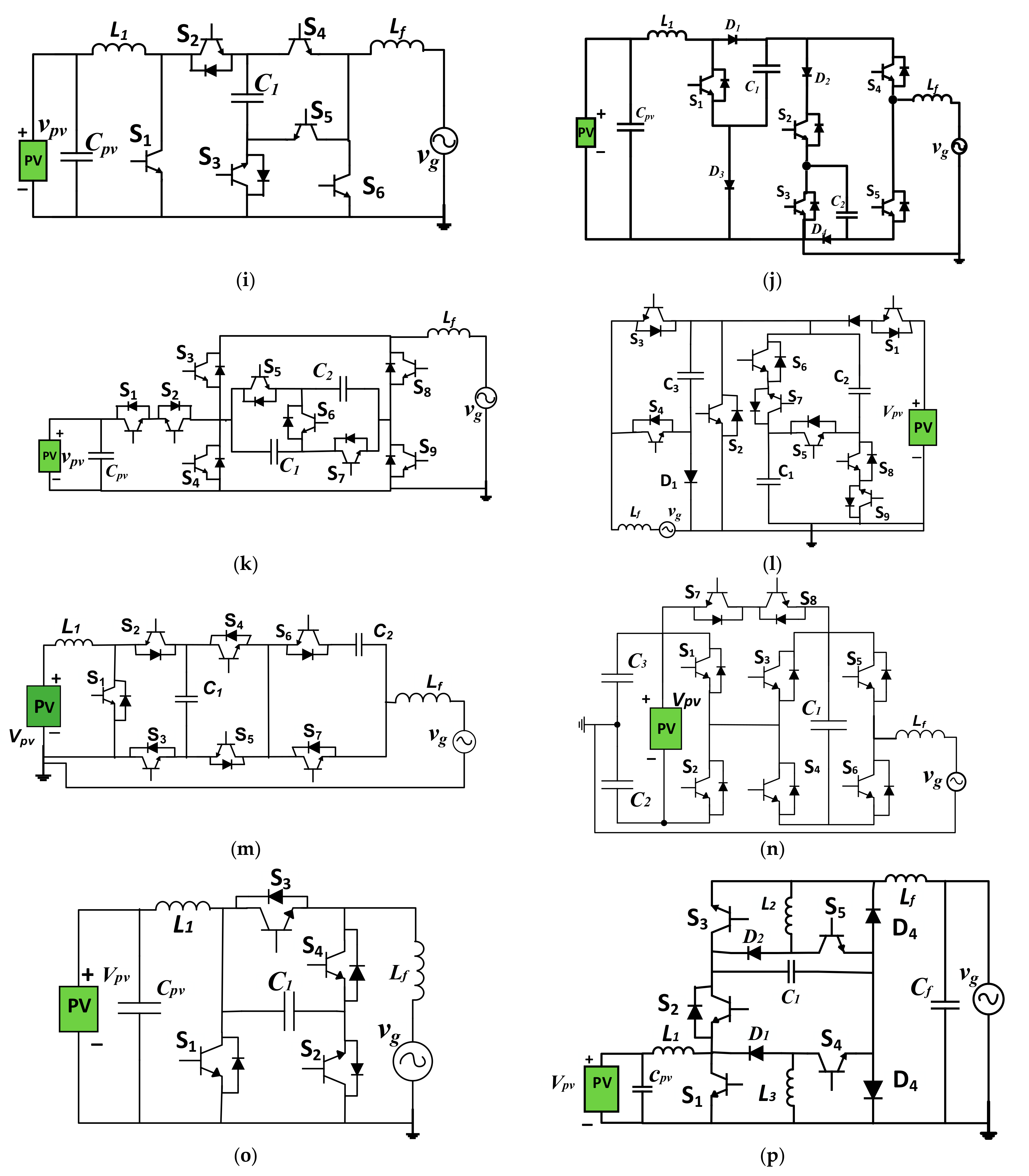
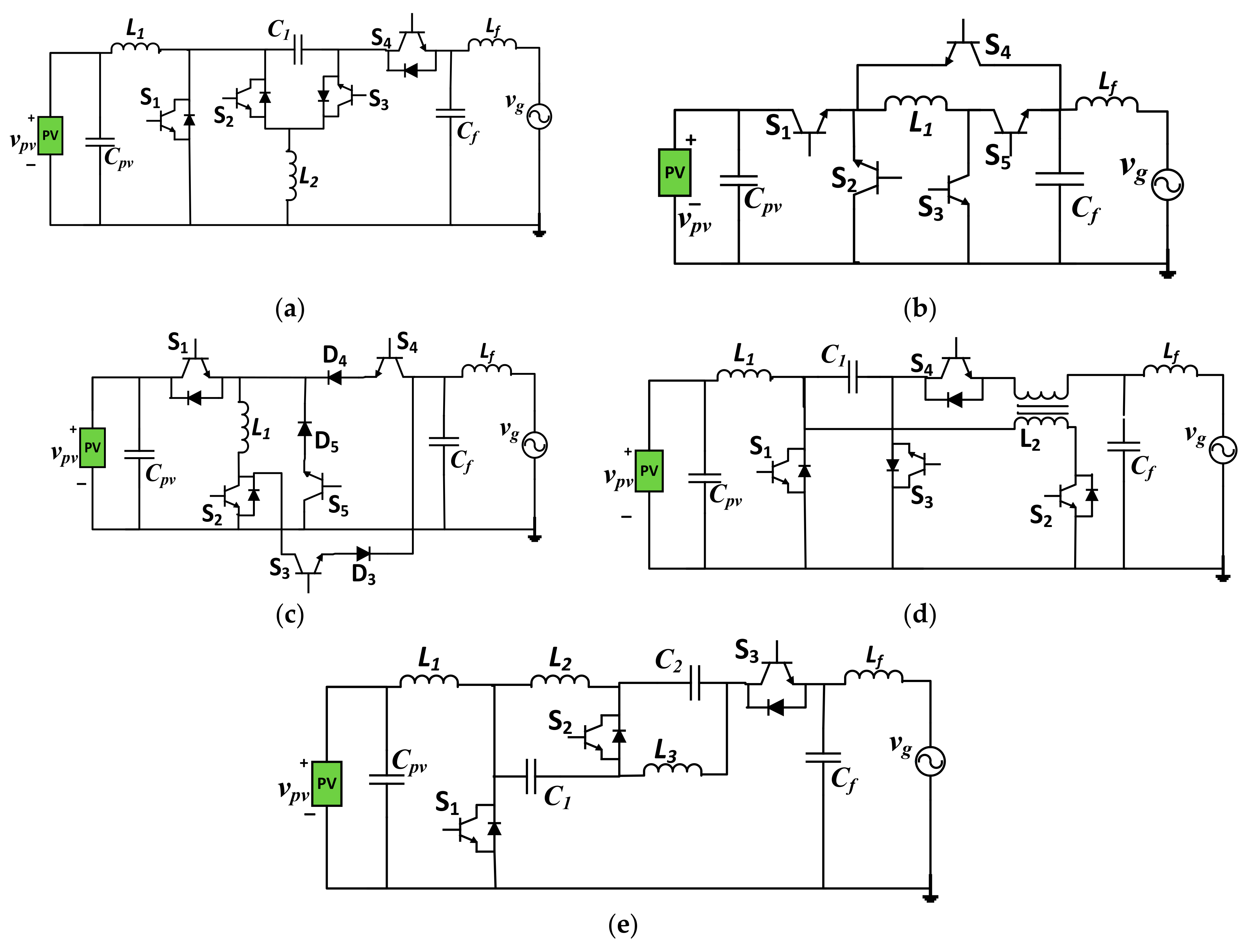
- The buck/boost CG inverter is presented in [82] and shown in Figure 6o. This inverter needs only four switches while it can offer continuous input current along with high boosting gain. In addition, it does not need a high capacitance value for power decoupling; only one capacitor with 100 uF has been adopted for the 2 kW prototype. This inverter does not use any diodes. The reported efficiency is about 96.5% for a 2 kW prototype. This inverter can offer only three voltage levels; thus, compared to other inverters with more voltage levels, a larger filter size is needed;
- The boost CG inverter is presented in [58,59] and shown in Figure 5e. This inverter can offer continuous input current along with high boosting gain. In addition, it does not need a high capacitance value for power decoupling; only one capacitor with 47 uF has been adopted for the 440 W prototype. This inverter needs five switches and does not use any diodes. The reported efficiency is about 95.5% for the 440 W prototype. This inverter can offer only three voltage levels. DC current component can be generated due to using an inequal number of switches during positive and negative half-cycles;
- The current-source CG inverter is presented in [36,37] and shown in Figure 3a. This inverter needs only four switches while it can offer continuous input current along with high boosting gain. This inverter does not use any diodes. The reported efficiency is about 95.7% for the 300 W prototype. However, it needs a high capacitance value for power decoupling; one capacitor with 2.2 mF has been used for the 300 W prototype. In addition, it needs two inductors (0.25 and 0.5 mH); this can increase the size and cost;
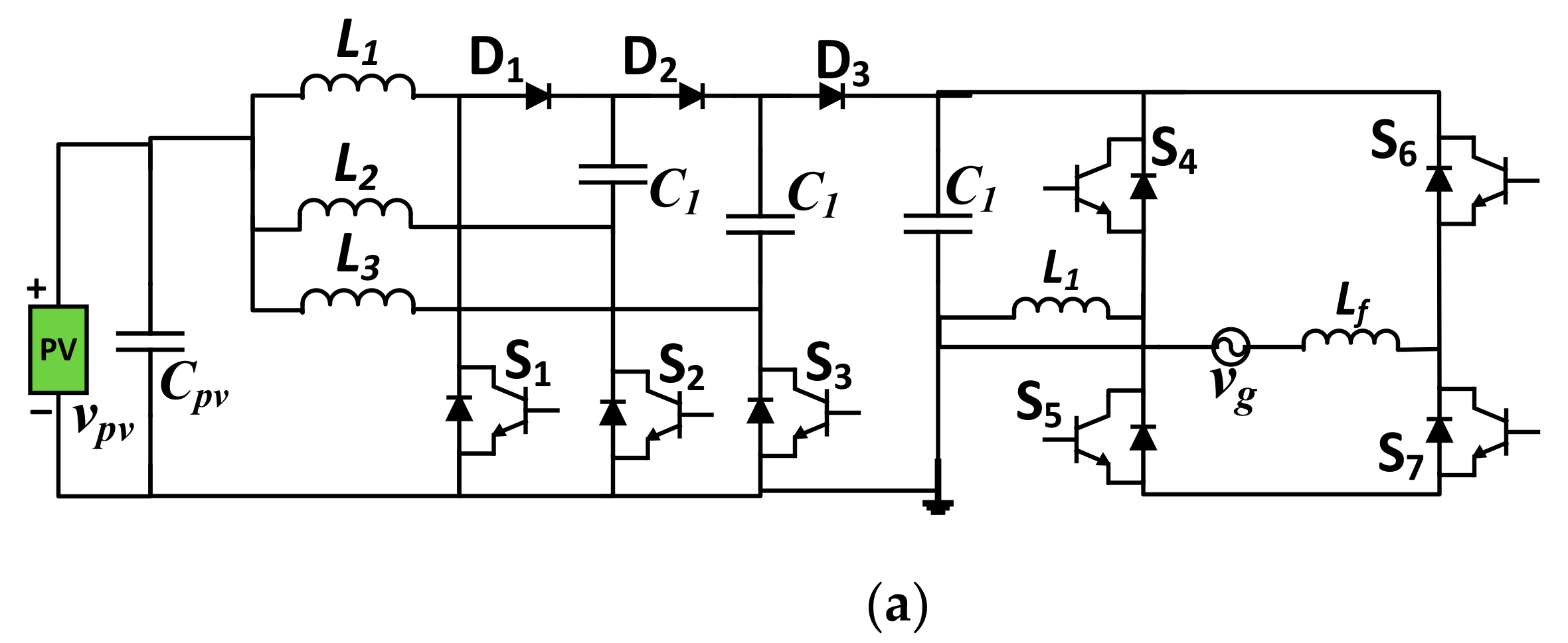
- The boost CG inverter is presented in [54] and shown in Figure 5a. This inverter can offer high boosting gain along with continuous input current. In addition, low capacitance and inductance values are needed. However, this inverter needs seven switches and three diodes; this increases its cost and decreases efficiency. This inverter can offer only three voltage levels. The reported efficiency is about 94.4% for the 300 W prototype;
- The boost CG inverter is presented in [63] and shown in Figure 5i. This inverter can offer five voltage levels, high boosting gain, and continuous input current. The reported efficiency is about 98.2% for a 1 kW prototype. However, this inverter needs 10 switches; this increases its cost along with operational complexity. In addition, it uses high capacitances; two capacitors with 0.94 and 0.47 mF are adopted for the 1 kW prototype;
- The buck/boost CG inverter is presented in [67,68] and shown in Figure 6d. This inverter can offer five voltage levels along with continuous input current. The reported efficiency is about 98.1% for the 600 W prototype. This inverter needs six switches and two diodes. In addition, it uses high capacitances. Its boosting gain is relatively low (2M).
4. Recommendations for Future Work
- Quantitative evaluation for the different common-ground converters to reflect their differences in terms of specific features;
- This could help multi-input CG converters: such converters can use a reduced number of switches to process the power from several PV sources without the need for a series connection. This can significantly reduce the cost and increase the power density;
- Modular multilevel CG converters: such inverters can offer a high number of voltage levels; thus, reduced filter size can be used;
- Developing high boosting gain CG converters applicable for module-integrated PV applications.
5. Conclusions
Author Contributions
Funding
Institutional Review Board Statement
Informed Consent Statement
Data Availability Statement
Conflicts of Interest
References
- Khan, N.H.; Forouzesh, M.; Siwakoti, Y.P.; Li, L.; Kerekes, T.; Blaabjerg, F. Transformerless Inverter Topologies for Single-Phase Photovoltaic Systems: A Comparative Review. IEEE J. Emerg. Sel. Top. Power Electron. 2019, 8, 805–835. [Google Scholar] [CrossRef]
- SolarPower Europe (2020): Global Market Outlook for Solar Power 2020–2024. Available online: https://www.solarpowereurope.org/global-market-outlook-2020-2024/ (accessed on 25 November 2021).
- Li, W.; Gu, Y.; Luo, H.; Cui, W.; He, X.; Xia, C. Topology Review and Derivation Methodology of Single-Phase Transformerless Photovoltaic Inverters for Leakage Current Suppression. IEEE Trans. Ind. Electron. 2015, 62, 4537–4551. [Google Scholar] [CrossRef]
- Dong, D.; Luo, F.; Boroyevich, D.; Mattavelli, P. Leakage Current Reduction in a Single-Phase Bidirectional AC–DC Full-Bridge Inverter. IEEE Trans. Power Electron. 2012, 27, 4281–4291. [Google Scholar] [CrossRef]
- Xiao, H.; Xie, S. Leakage Current Analytical Model and Application in Single-Phase Transformerless Photovoltaic Grid-Connected Inverter. IEEE Trans. Electromagn. Compat. 2010, 52, 902–913. [Google Scholar] [CrossRef]
- Kerekes, T. Analysis and Modeling of Transformerless Photovoltaic Inverter Systems. Ph.D. Thesis, Aalborg University, Aalborg, Denmark, 2009. [Google Scholar]
- Chen, W.; Yang, X.; Zhang, W.; Song, X. Leakage current calculation for PV inverter system based on a parasitic capacitor model. IEEE Trans. Power Electron. 2016, 31, 1. [Google Scholar] [CrossRef]
- Freddy, T.K.S.; Rahim, N.A.; Hew, W.-P.; Che, H.S. Comparison and Analysis of Single-Phase Transformerless Grid-Connected PV Inverters. IEEE Trans. Power Electron. 2014, 29, 5358–5369. [Google Scholar] [CrossRef]
- López, O.; Freijedo, F.D.; Yepes, A.G.; Fernández-Comesaña, P.; Malvar, J.; Teodorescu, R.; Doval-Gandoy, J. Eliminating Ground Current in a Transformerless Photovoltaic Application. IEEE Trans. Energy Convers. 2010, 25, 140–147. [Google Scholar] [CrossRef]
- Roy, J.; Xia, Y.; Ayyanar, R. Performance evaluation of single-phase transfomer-less PV inverter topologies. In Proceedings of the 2018 IEEE Applied Power Electronics Conference and Exposition (APEC), San Antonio, TX, USA, 4–8 March 2018; pp. 3250–3255. [Google Scholar] [CrossRef]
- Figueredo, R.S.; de Carvalho, K.C.M.; Matakas, L. Integrated common and differential mode filter applied to a single-phase transformerless PV microinverter with low leakage current. In Proceedings of the 2014 International Power Electronics Conference (IPEC-Hiroshima 2014—ECCE ASIA), Hiroshima, Japan, 18–21 May 2014; pp. 2618–2625. [Google Scholar] [CrossRef]
- Falvo, M.C.; Capparella, S. Safety issues in PV systems: Design choices for a secure fault detection and for preventing fire risk. Case Stud. Fire Saf. 2015, 3, 1–16. [Google Scholar] [CrossRef] [Green Version]
- Gonzalez, R.; Gubía, E.; Lopez, J.; Marroyo, L. Transformerless Single-Phase Multilevel-Based Photovoltaic Inverter. IEEE Trans. Ind. Electron. 2008, 55, 2694–2702. [Google Scholar] [CrossRef]
- Yan, Q.; Wu, X.; Yuan, X.; Geng, Y.; Zhang, Q. Minimization of the DC Component in Transformerless Three-Phase Grid-Connected Photovoltaic Inverters. IEEE Trans. Power Electron. 2015, 30, 3984–3997. [Google Scholar] [CrossRef]
- Zhang, W.; Armstrong, M.; Elgendy, M.A. Mitigation of DC Current Injection in Transformer-Less Grid-Connected Inverters Using a Voltage Filtering DC Extraction Approach. IEEE Trans. Energy Convers. 2019, 34, 426–434. [Google Scholar] [CrossRef]
- Ibrahim, E.A.D.; Gaafar, M.A.; Orabi, M.; Sheir, A.; Youssef, M.Z.; Abedeen, E. A Novel Dual-Input High-Gain Transformerless Multilevel Single-Phase Microinverter for PV Systems. IEEE Trans. Power Electron. 2020, 35, 4703–4714. [Google Scholar] [CrossRef]
- Abdeen, E.; Gaafar, M.A.; Orabi, M.; Ahmed, E.M.; El Aroudi, A. Multi-Input Ćuk-Derived Buck-Boost Voltage Source Inverter for Photovoltaic Systems in Microgrid Applications. Energies 2019, 12, 2007. [Google Scholar] [CrossRef] [Green Version]
- Gaafar, M.A.; Ibrahim, E.A.; Orabi, M. Multi-input transformer-less four-wire microinverter with distributed MPPT for PV systems. Int. J. Circuit Theory Appl. 2021, 49, 1704–1725. [Google Scholar] [CrossRef]
- VDE V 0126-1-1, Eigenerzeugungsanlagen am Niederspannungsnetz. 2013. Available online: https://www.dke.de/de/normen-standards/dokument?id=7032174&type=dke%7Cdokument (accessed on 25 November 2021).
- Characteristics of the Utility Interface for Photovoltaic (PV) Systems, IEC 61727 CDV. 2002. Available online: https://standards.globalspec.com/std/365170/IEC%2061727 (accessed on 25 November 2021).
- Akagi, H.; Tamura, S. A Passive EMI Filter for Eliminating Both Bearing Current and Ground Leakage Current From an Inverter-Driven Motor. IEEE Trans. Power Electron. 2006, 21, 1459–1469. [Google Scholar] [CrossRef]
- Lai, R.; Maillet, Y.; Wang, F.; Wang, S.; Burgos, R.; Boroyevich, D. An Integrated EMI Choke for Differential-Mode and Common-Mode Noise Suppression. IEEE Trans. Power Electron. 2010, 25, 539–544. [Google Scholar] [CrossRef]
- Xiao, H.; Xie, S.; Chen, Y.; Huang, R. An Optimized Transformerless Photovoltaic Grid-Connected Inverter. IEEE Trans. Ind. Electron. 2011, 58, 1887–1895. [Google Scholar] [CrossRef]
- Zhang, L.; Sun, K.; Xing, Y.; Xing, M. H6 Transformerless Full-Bridge PV Grid-Tied Inverters. IEEE Trans. Power Electron. 2014, 29, 1229–1238. [Google Scholar] [CrossRef]
- Guo, X.; Jia, X.; Lu, Z.; Guerrero, J.M. Single phase cascaded H5 inverter with leakage current elimination for transformerless photovoltaic system. In Proceedings of the 2016 IEEE Applied Power Electronics Conference and Exposition (APEC), Long Beach, CA, USA, 20–24 March 2016; pp. 398–401. [Google Scholar] [CrossRef] [Green Version]
- Yang, B.; Li, W.; Gu, Y.; Cui, W.; He, X. Improved Transformerless Inverter With Common-Mode Leakage Current Elimination for a Photovoltaic Grid-Connected Power System. IEEE Trans. Power Electron. 2012, 27, 752–762. [Google Scholar] [CrossRef]
- Bower, W.; Wiles, J. Analysis of grounded and ungrounded photovoltaic systems. In Proceedings of the 1994 IEEE 1st World Conference on Photovoltaic Energy Conversion—WCPEC (A Joint Conference of PVSC2002, PVSEC and PSEC), Waikoloa, HI, USA, 5–9 December 1994; pp. 809–812. [Google Scholar] [CrossRef] [Green Version]
- Estévez-Bén, A.A.; Alvarez-Diazcomas, A.; Macias-Bobadilla, G.; Rodríguez-Reséndiz, J. Leakage Current Reduction in Single-Phase Grid-Connected Inverters—A Review. Appl. Sci. 2020, 10, 2384. [Google Scholar] [CrossRef] [Green Version]
- Islam, M.; Mekhilef, S.; Hasan, M. Single phase transformerless inverter topologies for grid-tied photovoltaic system: A review. Renew. Sustain. Energy Rev. 2015, 45, 69–86. [Google Scholar] [CrossRef] [Green Version]
- Khan, A.; Ben-Brahim, L.; Gastli, A.; Benammar, M. Review and simulation of leakage current in transformerless microinverters for PV applications. Renew. Sustain. Energy Rev. 2017, 74, 1240–1256. [Google Scholar] [CrossRef]
- Islam, H.; Mekhilef, S.; Shah, N.B.M.; Soon, T.K.; Seyedmahmousian, M.; Horan, B.; Stojcevski, A. Performance Evaluation of Maximum Power Point Tracking Approaches and Photovoltaic Systems. Energies 2018, 11, 365. [Google Scholar] [CrossRef] [Green Version]
- Zakzouk, N.E.; Khamis, A.K.; Abdelsalam, A.K.; Williams, B.W. Continuous-Input Continuous-Output Current Buck-Boost DC/DC Converters for Renewable Energy Applications: Modelling and Performance Assessment. Energies 2019, 12, 2208. [Google Scholar] [CrossRef] [Green Version]
- Bughneda, A.; Salem, M.; Richelli, A.; Ishak, D.; Alatai, S. Review of Multilevel Inverters for PV Energy System Applications. Energies 2021, 14, 1585. [Google Scholar] [CrossRef]
- Zhang, J.; Xu, S.; Din, Z.; Hu, X. Hybrid Multilevel Converters: Topologies, Evolutions and Verifications. Energies 2019, 12, 615. [Google Scholar] [CrossRef] [Green Version]
- Grandi, G.; Ruderman, A. (Eds.) Multilevel Converters: Analysis, Modulation, Topologies, and Applications; MDPI: Basel, Switzerland, 2019. [Google Scholar] [CrossRef]
- Kumar, A.; Sensarma, P. A Four-Switch Single-Stage Single-Phase Buck–Boost Inverter. IEEE Trans. Power Electron. 2017, 32, 5282–5292. [Google Scholar] [CrossRef]
- Kumar, A.; Sensarma, P. New Switching Strategy for Single-Mode Operation of a Single-Stage Buck–Boost Inverter. IEEE Trans. Power Electron. 2018, 33, 5927–5936. [Google Scholar] [CrossRef]
- Azary, M.T.; Sabahi, M.; Babaei, E.; Meinagh, F.A.A. Modified Single-Phase Single-Stage Grid-Tied Flying Inductor Inverter With MPPT and Suppressed Leakage Current. IEEE Trans. Ind. Electron. 2018, 65, 221–231. [Google Scholar] [CrossRef]
- Patel, H.; Agarwal, V. A Single-Stage Single-Phase Transformer-Less Doubly Grounded Grid-Connected PV Interface. IEEE Trans. Energy Convers. 2009, 24, 93–101. [Google Scholar] [CrossRef]
- Gautam, V.; Kumar, A.; Sensarma, P. A novel single stage, transformerless PV inverter. In Proceedings of the 2014 IEEE International Conference on Industrial Technology (ICIT), Busan, Korea, 26 February–1 March 2014; pp. 907–912. [Google Scholar] [CrossRef]
- Huang, L.; Zhang, M.; Hang, L.; Yao, W.; Lu, Z. A Family of Three-Switch Three-State Single-Phase $Z$-Source Inverters. IEEE Trans. Power Electron. 2013, 28, 2317–2329. [Google Scholar] [CrossRef]
- Siwakoti, Y.P.; Blaabjerg, F. Common-Ground-Type Transformerless Inverters for Single-Phase Solar Photovoltaic Systems. IEEE Trans. Ind. Electron. 2018, 65, 2100–2111. [Google Scholar] [CrossRef]
- Siwakoti, Y.P.; Blaabjerg, F. A novel flying capacitor transformerless inverter for single-phase grid connected solar photovoltaic system. In Proceedings of the 2016 IEEE 7th International Symposium on Power Electronics for Distributed Generation Systems (PEDG), Vancouver, BC, Canada, 27–30 June 2016; pp. 1–6. [Google Scholar] [CrossRef]
- Siwakoti, Y.P.; Blaabjerg, F. H-Bridge transformerless inverter with common ground for single-phase solar-photovoltaic system. In Proceedings of the 2017 IEEE Applied Power Electronics Conference and Exposition (APEC), Tampa, FL, USA, 26–30 March 2017; pp. 2610–2614. [Google Scholar] [CrossRef]
- Xia, Y.; Roy, J.; Ayyanar, R. A Capacitance-Minimized, Doubly Grounded Transformer less Photovoltaic Inverter with Inherent Active-Power Decoupling. IEEE Trans. Power Electron. 2017, 32, 5188–5201. [Google Scholar] [CrossRef]
- Ardashir, J.F.; Sabahi, M.; Hosseini, S.H.; Blaabjerg, F.; Babaei, E.; Gharehpetian, G.B. A Single-Phase Transformerless Inverter with Charge Pump Circuit Concept for Grid-Tied PV Applications. IEEE Trans. Ind. Electron. 2017, 64, 5403–5415. [Google Scholar] [CrossRef]
- Gu, Y.; Li, W.; Zhao, Y.; Yang, B.; Li, C.; He, X. Transformerless Inverter With Virtual DC Bus Concept for Cost-Effective Grid-Connected PV Power Systems. IEEE Trans. Power Electron. 2013, 28, 793–805. [Google Scholar] [CrossRef]
- Kadam, A.; Shukla, A. A Multilevel Transformerless Inverter Employing Ground Connection Between PV Negative Terminal and Grid Neutral Point. IEEE Trans. Ind. Electron. 2017, 64, 8897–8907. [Google Scholar] [CrossRef]
- Liao, Z.; Cao, C.; Qiu, D.; Xu, C. Single-Phase Common-Ground-Type Transformerless PV Grid-Connected Inverters. IEEE Access 2019, 7, 63276–63287. [Google Scholar] [CrossRef]
- Vazquez, N.; Rosas, M.; Hernandez, C.; Vazquez, E.; Perez-Pinal, F. A New Common-Mode Transformerless Photovoltaic Inverter. IEEE Trans. Ind. Electron. 2015, 62, 6381–6391. [Google Scholar] [CrossRef]
- Sandeep, N.; Sathik, J.; Yaragatti, U.R.; Krishnasamy, V.; Verma, A.; Pota, H. Common-Ground-Type Five-Level Transformerless Inverter Topology with Full DC-Bus Utilizaton. IEEE Trans. Ind. Appl. 2020, 56, 4071–4080. [Google Scholar] [CrossRef]
- Grigoletto, F.B. Five-Level Transformerless Inverter for Single-Phase Solar Photovoltaic Applications. IEEE J. Emerg. Sel. Top. Power Electron. 2020, 8, 3411–3422. [Google Scholar] [CrossRef]
- Grigoletto, F.B. Multilevel Common-Ground Transformerless Inverter for Photovoltaic Applications. IEEE J. Emerg. Sel. Top. Power Electron. 2021, 9, 831–842. [Google Scholar] [CrossRef]
- Roy, J.; Xia, Y.; Ayyanar, R. High Step-up Transformerless Inverter for AC Module Applications with Active Power Decoupling. IEEE Trans. Ind. Electron. 2019, 66, 3891–3901. [Google Scholar] [CrossRef]
- Chamarthi, P.K.; El Moursi, M.S.; Khadkikar, V.; Al Hosani, K.H. A New Step-Up Transformerless Inverter Topology for 1-ɸ Grid-connected Solar Photovoltaic System. In Proceedings of the 2020 IEEE International Conference on Power Electronics, Smart Grid and Renewable Energy (PESGRE2020), Cochin, India, 2–4 January 2020; pp. 1–6. [Google Scholar] [CrossRef]
- Chamarthi, P.K.; El Moursi, M.S.; Al Hosani, K.H.; Al Durra, A.; Khadkikar, V. A New High Gain Transformerless Inverter for Single Phase Grid-connected Solar PV Application. In Proceedings of the 2019 9th International Conference on Power and Energy Systems (ICPES), Perth, Australia, 10–12 December 2019; pp. 1–6. [Google Scholar] [CrossRef]
- Tran, T.-T.; Nguyen, M.-K.; Lim, Y.-C.; Choi, J.-H. A Single-Phase Common Ground Boost Inverter for Photovoltaic Applications. In Proceedings of the 2018 International Power Electronics Conference (IPEC-Niigata 2018 -ECCE Asia), Niigata, Japan, 20–24 May 2018; pp. 1799–1802. [Google Scholar] [CrossRef]
- Hu, X.; Ma, P.; Gao, B.; Zhang, M. An Integrated Step-up Inverter without Transformer and Leakage Current for Grid-Connected Photovoltaic System. IEEE Trans. Power Electron. 2019, 34, 9814–9827. [Google Scholar] [CrossRef]
- Lee, S.S.; Siwakoti, Y.P.; Lim, C.S.; Lee, K.-B. An Improved PWM Technique to Achieve Continuous Input Current in Common-Ground Transformerless Boost Inverter. IEEE Trans. Circuits Syst. II Express Briefs 2020, 67, 3133–3136. [Google Scholar] [CrossRef]
- Sarikhani, A.; Ghaderi, M.H.; Hamzeh, M. A Common-Ground Quazi-Z-Source Single-Phase Inverter Suitable for Photovoltaic Applications. IEEE Trans. Energy Convers. 2021, 36, 594–601. [Google Scholar] [CrossRef]
- Kim, K.; Cha, H.; Kim, H.-G. A New Single-Phase Switched-Coupled-Inductor DC–AC Inverter for Photovoltaic Systems. IEEE Trans. Power Electron. 2017, 32, 5016–5022. [Google Scholar] [CrossRef]
- Vosoughi, N.; Hosseini, S.H.; Sabahi, M. A New Transformer-Less Five-Level Grid-Tied Inverter for Photovoltaic Applications. IEEE Trans. Energy Convers. 2020, 35, 106–118. [Google Scholar] [CrossRef]
- Barzegarkhoo, R.; Lee, S.S.; Siwakoti, Y.P.; Khan, S.A.; Blaabjerg, F. Design, Control, and Analysis of a Novel Grid-Interfaced Switched-Boost Dual T-Type Five-Level Inverter with Common-Ground Concept. IEEE Trans. Ind. Electron. 2021, 68, 8193–8206. [Google Scholar] [CrossRef]
- Rajeev, M.; Agarwal, V. Novel transformer-less inverter topology for single-phase grid connected photovoltaic system. In Proceedings of the 2015 IEEE 42nd Photovoltaic Specialist Conference (PVSC), New Orleans, LA, USA, 14–19 June 2015; pp. 1–5. [Google Scholar] [CrossRef]
- Vosoughi, N.; Hosseini, S.H.; Sabahi, M. A New Single-Phase Transformerless Grid-Connected Inverter with Boosting Ability and Common Ground Feature. IEEE Trans. Ind. Electron. 2020, 67, 9313–9325. [Google Scholar] [CrossRef]
- Cao, D.; Jiang, S.; Yu, X.; Peng, F.Z. Low-Cost Semi-Z-source Inverter for Single-Phase Photovoltaic Systems. IEEE Trans. Power Electron. 2011, 26, 3514–3523. [Google Scholar] [CrossRef]
- Barzegarkhoo, R.; Siwakoti, Y.P.; Long, T.; Blaabjerg, F. Five-Level Grid-Tied Inverter Employing Switched-Capacitor Cell with Common-Grounded Feature. In Proceedings of the 2020 IEEE Applied Power Electronics Conference and Exposition (APEC), New Orleans, LA, USA, 15–19 March 2020; pp. 3298–3303. [Google Scholar] [CrossRef]
- Barzegarkhoo, R.; Siwakoti, Y.P.; Vosoughi, N.; Blaabjerg, F. Six-Switch Step-Up Common-Grounded Five-Level Inverter with Switched-Capacitor Cell for Transformerless Grid-Tied PV Applications. IEEE Trans. Ind. Electron. 2021, 68, 1374–1387. [Google Scholar] [CrossRef]
- Chamarthi, P.; Rajeev, M.; Agarwal, V. A novel single stage zero leakage current transformer-less inverter for grid connected PV systems. In Proceedings of the 2015 IEEE 42nd Photovoltaic Specialist Conference (PVSC), New Orleans, LA, USA, 14–19 June 2015; pp. 1–5. [Google Scholar] [CrossRef]
- Gautam, V.; Sensarma, P. Design of Ćuk-Derived Transformerless Common-Grounded PV Microinverter in CCM. IEEE Trans. Ind. Electron. 2017, 64, 6245–6254. [Google Scholar] [CrossRef]
- Jamatia, A.; Gautam, V.; Sensarma, P. Power Decoupling for Single-Phase PV System Using Ćuk Derived Microinverter. IEEE Trans. Ind. Appl. 2018, 54, 3586–3595. [Google Scholar] [CrossRef]
- Chamarthi, P.K.; Gupta, A.K.; Joshi, M.S.; Agarwal, V.; Ochoa, M.; García, I.; Lombardero, I.; Ayllón, L.; Cifuentes, L.; Rey-Stolle, I.; et al. A Single-Stage uk-based Transformerless Inverter for 1-ϕ Grid-Connected PV Systems. In Proceedings of the 2017 IEEE 44th Photovoltaic Specialist Conference (PVSC), Washington, DC, USA, 25–30 June 2017; pp. 2952–2956. [Google Scholar] [CrossRef]
- Chamarthi, P.K.; El Moursi, M.S.; Khadkikar, V.; Al Hosani, K.H. A Novel Single-Stage Buck-Boost Transformerless Inverter for 1-ϕ Grid-Connected Solar PV Systems. In Proceedings of the 2020 IEEE Applied Power Electronics Conference and Exposition (APEC), New Orleans, LA, USA, 15–19 March 2020; pp. 3341–3345. [Google Scholar] [CrossRef]
- Rajeev, M.; Agarwal, V. Closed loop control of novel transformer-less inverter topology for single phase grid connected photovoltaic system. In Proceedings of the 2016 IEEE Power and Energy Conference at Illinois (PECI), Urbana, IL, USA, 19–20 February 2016; pp. 1–7. [Google Scholar] [CrossRef]
- Tran, T.-T.; Nguyen, M.-K.; Choi, J.-H.; Lim, Y.-C. A Single-Phase Common-Ground-Type Boost Inverter for Photovoltaic Applications. In Proceedings of the 2019 21st European Conference on Power Electronics and Applications (EPE ’19 ECCE Europe), Genova, Italy, 3–5 September 2019; pp. pp. P.1–P.8. [CrossRef]
- Khan, N.H.; Siwakoti, Y.P.; Scott, M.J.; Li, L.; Khan, S.A.; Lu, D.D.-C.; Barzegarkhoo, R.; Sidorski, F.; Blaabjerg, F.; Hasan, S.U. A Common Grounded Type Dual-Mode Five-Level Transformerless Inverter for Photovoltaic Applications. IEEE Trans. Ind. Electron. 2021, 68, 9742–9754. [Google Scholar] [CrossRef]
- Khan, N.H.; Siwakoti, Y.P.; Scott, M.J.; Hasan, S.U.; Shaffer, B.; Li, L.; Khan, S.A.; Blaabjerg, F. A Common Ground-type Single-Phase Dual Mode Five-Level Switched-Capacitor Transformerless Inverter. In Proceedings of the 2020 IEEE Applied Power Electronics Conference and Exposition (APEC), New Orleans, LA, USA, 15–19 March 2020; pp. 436–441. [Google Scholar] [CrossRef]
- Shaffer, B.; Hassan, H.A.; Scott, M.J.; Hasan, S.U.; Town, G.E.; Siwakoti, Y. A common-ground single-phase five-level transformerless boost inverter for photovoltaic applications. In Proceedings of the 2008 IEEE Applied Power Electronics Conference and Exposition (APEC), San Antonio, TX, USA, 4–8 March 2018; pp. 368–374. [Google Scholar] [CrossRef]
- Barzegarkhoo, R.; Siwakoti, Y.P.; Aguilera, R.P.; Khan, N.H.; Lee, S.S.; Blaabjerg, F. A Novel Dual-Mode Switched-Capacitor Five-Level Inverter with Common-Ground Transformerless Concept. IEEE Trans. Power Electron. 2021, 36, 13740–13753. [Google Scholar] [CrossRef]
- Lee, S.S.; Yang, Y.; Siwakoti, Y.P. A Novel Single-Stage Five-Level Common-Ground-Boost-Type Active Neutral-Point-Clamped (5L-CGBT-ANPC) Inverter. IEEE Trans. Power Electron. 2021, 36, 6192–6196. [Google Scholar] [CrossRef]
- Chaurasia, A.; Hota, A. A Novel Switched Capacitor 4-level Single-Phase Inverter with Voltage Boosting and Common Ground. In Proceedings of the 2020 IEEE International Conference on Power Electronics, Drives and Energy Systems (PEDES), Jaipur, India, 16–19 December 2020; pp. 1–4. [Google Scholar] [CrossRef]
- Xu, X.; Su, M.; Sun, Y.; Guo, B.; Wang, H.; Xu, G. Four-Switch Single-Phase Common-Ground PV Inverter with Active Power Decoupling. IEEE Trans. Ind. Electron. 2021. [Google Scholar] [CrossRef]
- Ahmed, H.F.; El Moursi, M.S.; Zahawi, B.; Al Hosani, K.H. Single-Phase Photovoltaic Inverters With Common-Ground and Wide Buck–Boost Voltage Operation. IEEE Trans. Ind. Inform. 2021, 17, 8275–8287. [Google Scholar] [CrossRef]


| Leakage Current Value (mA) | Disconnection Time (msec) |
|---|---|
| 30 | 300 |
| 60 | 150 |
| 100 | 40 |
| Mitigation Method | Advantages | Disadvantages | |
|---|---|---|---|
| Using transformer-based converters |
|
| |
| Mitigation methods in transformer-less converters | Using common-mode (CM) chokes |
|
|
| Keeping constant CMV |
|
| |
| Using common-ground converters |
|
| |
| Converter | Features | Limitations |
|---|---|---|
| Refs. [36,37] |
|
|
| Ref. [38] |
|
|
| Ref. [39] |
|
|
| Ref. [40] |
|
|
| Ref. [41] |
|
|
| Converter | Features | Limitations |
|---|---|---|
| Refs. [42,43,44] |
|
|
| Ref. [45] |
|
|
| Ref. [46] |
|
|
| Ref. [47] |
|
|
| Ref. [48] |
|
|
| Ref. [49] |
|
|
| Ref. [50] |
|
|
| Ref. [51] |
|
|
| Ref. [52] |
|
|
| Ref. [53] |
|
|
| Converter | Features | Limitations |
|---|---|---|
| Ref. [54] |
|
|
| Ref. [55] |
|
|
| Ref. [56] |
|
|
| Ref. [57] |
|
|
| Refs. [58,59] |
|
|
| Ref. [60] |
|
|
| Ref. [61] |
|
|
| Ref. [62] |
|
|
| Ref. [63] |
|
|
| Converter | Features | Limitations |
|---|---|---|
| Ref. [64] |
|
|
| Ref. [65] |
|
|
| Ref. [66] |
|
|
| Refs. [67,68] |
|
|
| Ref. [69] |
|
|
| Refs. [70,71] |
|
|
| Ref. [72] |
|
|
| Ref. [73] |
| |
| Ref. [74] |
|
|
| Ref. [75] |
|
|
| Refs. [76,77,78] |
|
|
| Ref. [79] |
|
|
| Ref. [80] |
|
|
| Ref. [81] |
|
|
| Ref. [82] |
|
|
| Ref. [83] |
|
|
Publisher’s Note: MDPI stays neutral with regard to jurisdictional claims in published maps and institutional affiliations. |
© 2021 by the authors. Licensee MDPI, Basel, Switzerland. This article is an open access article distributed under the terms and conditions of the Creative Commons Attribution (CC BY) license (https://creativecommons.org/licenses/by/4.0/).
Share and Cite
Gaafar, M.A.; Orabi, M.; Ibrahim, A.; Kennel, R.; Abdelrahem, M. Common-Ground Photovoltaic Inverters for Leakage Current Mitigation: Comparative Review. Appl. Sci. 2021, 11, 11266. https://doi.org/10.3390/app112311266
Gaafar MA, Orabi M, Ibrahim A, Kennel R, Abdelrahem M. Common-Ground Photovoltaic Inverters for Leakage Current Mitigation: Comparative Review. Applied Sciences. 2021; 11(23):11266. https://doi.org/10.3390/app112311266
Chicago/Turabian StyleGaafar, Mahmoud A., Mohamed Orabi, Ahmed Ibrahim, Ralph Kennel, and Mohamed Abdelrahem. 2021. "Common-Ground Photovoltaic Inverters for Leakage Current Mitigation: Comparative Review" Applied Sciences 11, no. 23: 11266. https://doi.org/10.3390/app112311266
APA StyleGaafar, M. A., Orabi, M., Ibrahim, A., Kennel, R., & Abdelrahem, M. (2021). Common-Ground Photovoltaic Inverters for Leakage Current Mitigation: Comparative Review. Applied Sciences, 11(23), 11266. https://doi.org/10.3390/app112311266