Article

FD-LTDA-MAC: Full-Duplex Unsynchronised Scheduling in Linear Underwater Acoustic Chain Networks

Department of Electronic Engineering, University of York, York YO10 5DD, UK
*
Author to whom correspondence should be addressed.
Appl. Sci. 2021, 11(22), 10967; https://doi.org/10.3390/app112210967
Submission received: 8 October 2021 / Revised: 3 November 2021 / Accepted: 16 November 2021 / Published: 19 November 2021
(This article belongs to the Special Issue Autonomy and Cooperation in Unmanned Surface and Underwater Vehicles)

Abstract

:
In-band full-duplex communication offers significant potential to enhance network performance. This paper presents the full-duplex linear transmit delay allocation MAC (FD-LTDA-MAC) protocol for full-duplex based underwater acoustic chain networks (FD-UACNs) for subsea pipeline monitoring. This incorporates a number of extensions to the LTDA-MAC protocol in order to fully exploit advantages of full-duplex communication to enhance the efficiency of underwater facility monitoring. The protocol uses a greedy optimisation algorithm to derive collision-free packet schedules for delivering data packets to the sink node of the underwater chain network. The purpose of this paper is to show the significant improvement that can be achieved in packet scheduling by exploiting temporal spectrum re-use of an underwater acoustic channel through full-duplex communication. Simulation results show that more efficient packet scheduling and reduced end-to-end packet delays can be achieved in large scale scenarios using FD-LTDA-MAC compared with LTDA-MAC and LTDA-MAC with full-duplex enabled nodes. It can provide much higher monitoring rates for long range underwater pipelines using low cost, mid range, low rate, and low power acoustic modems.

1. Introduction

A recent research into underwater acoustic communication, sensor and acoustic modem technologies has paved the way for various undersea and ocean operations [1,2,3,4,5]. Emerging application areas include oceanographic exploration for marine life, archaeological studies, and marine search and rescue missions. Other important applications, such as improved offshore petroleum exploration, monitoring, and control of underwater pipelines, border and military operations, fish farming, freshwater reservoir management, and tsunami and sea quake early warning systems [1,2,3,4,5] are also being explored.
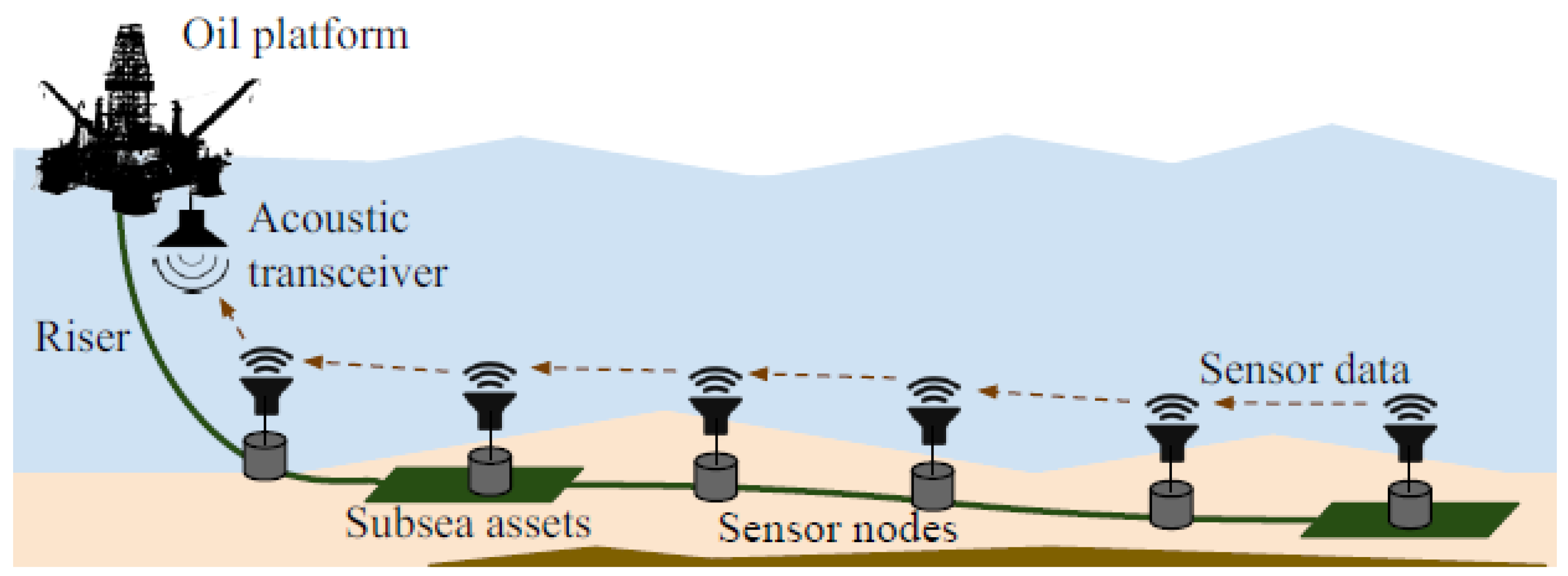
Monitoring subsea oil and gas infrastructure is a key application area of underwater acoustic sensor technology. This is because there are a number of underwater pipeline networks spanning long distances such as the Langeled pipeline in the North Sea measuring about 1200 km [6]. Most of these pipelines carry petroleum products. Timely detection of leakages and corrosion along these pipelines is critical in order to avoid financial loss and, more importantly, prevent water body pollution caused by oil spillage. Thus, for effective live monitoring of these pipelines, a multi-hop linear network topology is employed whereby packets are relayed from a source nodes via the neighbouring nodes to one or more sink nodes. A typical multi-hop topology linear underwater pipeline sensor network based monitoring system is shown in Figure 1.
Acoustic waves are preferable for underwater communication because they propagate much further than electromagnetic and optical waves [7]. Acoustic systems can also operate with lower transmission power compared to electromagnetic and optical systems [1]. However, establishment of communication among nodes underwater is a challenging task because of the complicated underwater channel characteristics, slow propagation of sound waves, and limited usable frequency bandwidth [3,8,9,10]. These challenges (notably long propagation delays and low available bandwidth) have made designing medium access control (MAC) protocols for underwater networks difficult [1,7]. This has also made the traditional MAC approaches unsuitable or only able to provide poor network performance.
Various MAC protocols that operate in a half-duplex fashion have been developed in order to improve network performance in UANs. Orthogonal access schemes, such as Time Division Multiple Access (TDMA), Frequency Division Multiple Access (FDMA), Code Division Multiple Access (CDMA), and Space Division Multiple Access (SDMA), involve the division of resources (time, frequency, code, and space) into sub-resources to enable collision-free channel access for the network nodes [12]. Alternative approaches to sharing a single channel among a group of users are either scheduling or contention based. Contention based schemes utilise carrier sensing, handshaking, or random access techniques [12] to access a shared channel. However, problems of quality of service (QoS) and energy efficiency still persist, mainly due to long propagation delays and limited available bandwidth in the underwater channel [13]. These network performance problems become more evident in multi-hop UANs. Time-based synchronisation schemes may be an option for short term applications, however, maintaining synchronisation is challenging in underwater networks and may incur significant overheads and, thus, makes synchronisation-based access techniques less viable. In the same vein, long propagation delays also create some uncertainty around channel idle/busy status prediction, which reduces the effectiveness of carrier sense protocols in UANs and this is amplified in multi-hop UANs. Additionally, handshaking techniques as employed in Request-To-Send/Clear-To-Send (RTS/CTS) based protocols [14,15,16,17] are also highly impacted by long propagation delay, since they can create significant idle time on the channel challenging their suitability for multi-hop UANs. The LTDA-MAC protocol provides better network performance and improved efficiency by using optimised packet scheduling in linear UASN-based pipeline monitoring systems without clock synchronisation at the sensor nodes [11,18] for short pipeline half-duplex linear underwater networks. However, this protocol performs poorly for long pipeline scenarios as packet schedules become extremely long, which reduces the frequency at which sensor data can be delivered to the required destination.
With the recent advances in self-interference cancellation for in-band full-duplex communication (a phenomenon whereby network nodes can transmit and receive data packets simultaneously within the same frequency bandwidth), new opportunities are on the horizon for improving spectral use and throughput in acoustic communication systems [19,20] are available. Interestingly, this can solve some of the MAC layer problems by potentially improving network performance in terms of providing higher throughput, lower latency, and by providing an opportunity for a node to simultaneously sense the channel while receiving a packet [21,22,23]. This has motivated the design of a new LTDA-MAC protocol for full-duplex based underwater chain network scenarios.
The LTDA-MAC protocol is designed to generate efficient collision-free packet schedules with significantly shorter frame duration. It can leverage full-duplex communications. This can significantly enhance spatial spectrum reuse, especially in the long range pipeline scenarios. We explored the benefit of full-duplex in [24], which investigated the potential performance gains that can be achieved in full-duplex network scenarios by switching on full-duplex capabilities without having to change the LTDA-MAC protocol. Although simultaneous packet scheduling in the full-duplex nodes achieved collision-free packet schedules with up to 39% and 34% throughput improvement for simple (short pipeline) and challenging (long pipeline) cases, respectively, compared to the half-duplex case, it was observed that spatial re-use could be improved especially for longer pipelines by designing a new protocol capable of fully exploiting the full-duplex capabilities of nodes.
This paper proposes the FD-LTDA-MAC protocol which is designed to achieve further performance improvement by re-developing the traditional LTDA-MAC protocol to fully exploit full-duplex capabilities and enhance spatial reuse for full-duplex underwater multi-hop chain networks. Consequently, this protocol provides much more efficient packet scheduling to achieve higher monitoring rates over long range underwater pipelines using low cost, mid range, low rate, and low power acoustic modems, such as those presented in [25]. This study is based on numerical simulation and a BELLHOP [26] based underwater channel model. It builds on prior work, in particular, related to the LTDA-MAC protocol. Hence, this paper presents a new protocol designed for full-duplex communication in linear networks.
The remainder of this work is organised as follows. Section 2 provides a description of the FD-LTDA-MAC protocol, while, the simulation scenarios are presented in Section 3. Section 4 presents the numerical results and discussion, and conclusions are provided in Section 5.

2. FD-LTDA-MAC Protocol

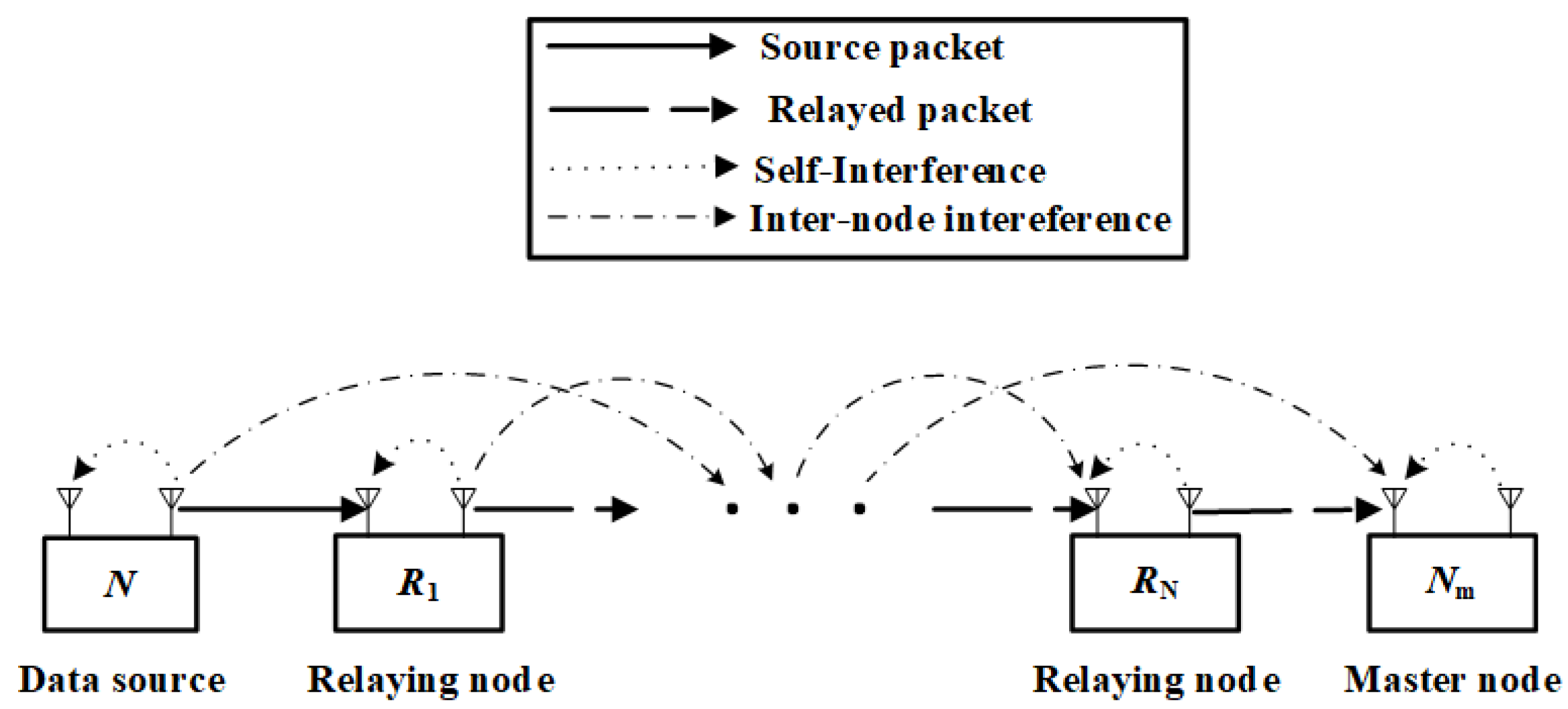
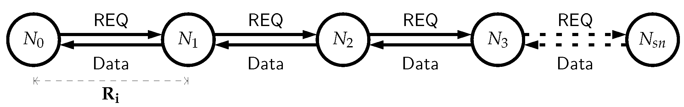
The FD-LTDA-MAC protocol is developed for full-duplex underwater multi-hop chain networks. It is an unsynchronised protocol that locally derives transmission times at the nodes by measuring the delays between nodes receiving a request (REQ) packet and transmitting their data packets. Consider a conceptual diagram of multi-hop chain Full-Duplex Relay (FDR) network shown in Figure 2.
Each sensor node utilises two-way connections, it connects to the node one hop closer to the sink node up the chain and to a node further down the chain. Upon receiving an REQ packet, transmitting nodes forward REQ packets down the chain to the last node. Every transmitting node responds to the REQ packet query by either acting as a source node and transmitting its own data packet up the chain or by acting as a relay node forwarding data packets up the chain that it received from the node further down the chain. The sink node is responsible for sending the REQ packets to request data packets from the transmitting nodes and to handle eventual reception of data packets from the transmitting nodes. The last transmitting node down the chain does not relay packets, it only transmits its own data packets. Every transmitting node serves as a data source or data forwarder except the last transmitting node, which serves only as a data source. It is assumed that the self-interference is totally cancelled. The new linear constraint is based on full-duplex communication structure to calculate transmit delays for an enhanced packet forwarding among full-duplex nodes. Additionally, a greedy scheduling algorithm uses full-duplex based initial starting point of search, this reduces the time wasted in waiting for an interference lapse before beginning a new transmission and the corresponding propagation delay components.
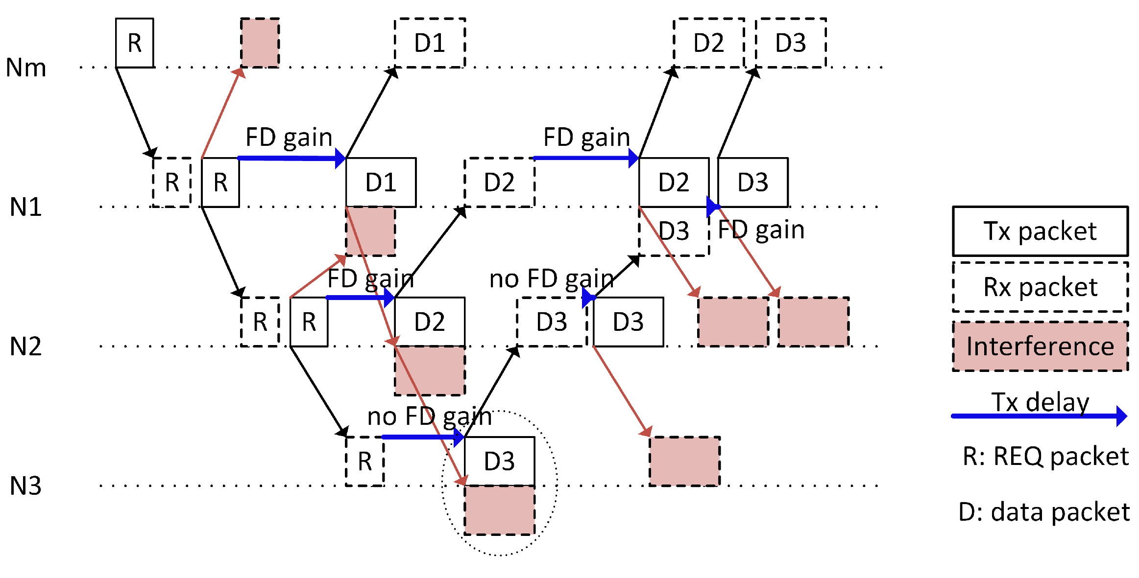
The timing diagram of the FD-LTDA MAC schedule for a typical one-hop interference range full-duplex underwater chain network is shown in Figure 3. It consists of a master node, N m , which serves as the sink node, and three transmitting sensor nodes, N 1 , N 2 , and N 3 . The master node broadcasts REQ packets down the chain through nodes N 1 and N 2 to node N 3 . Nodes N 1 and N 2 forward the REQ packets after an allowable guard interval, τ g . Upon the reception of a REQ packet by a node, it generates and schedules data packet for transmission or schedules forwarding of a relayed packet up the chain towards N m after waiting a certain time called transmit delay. The wait time accounts for only REQ packet interval, τ r p 
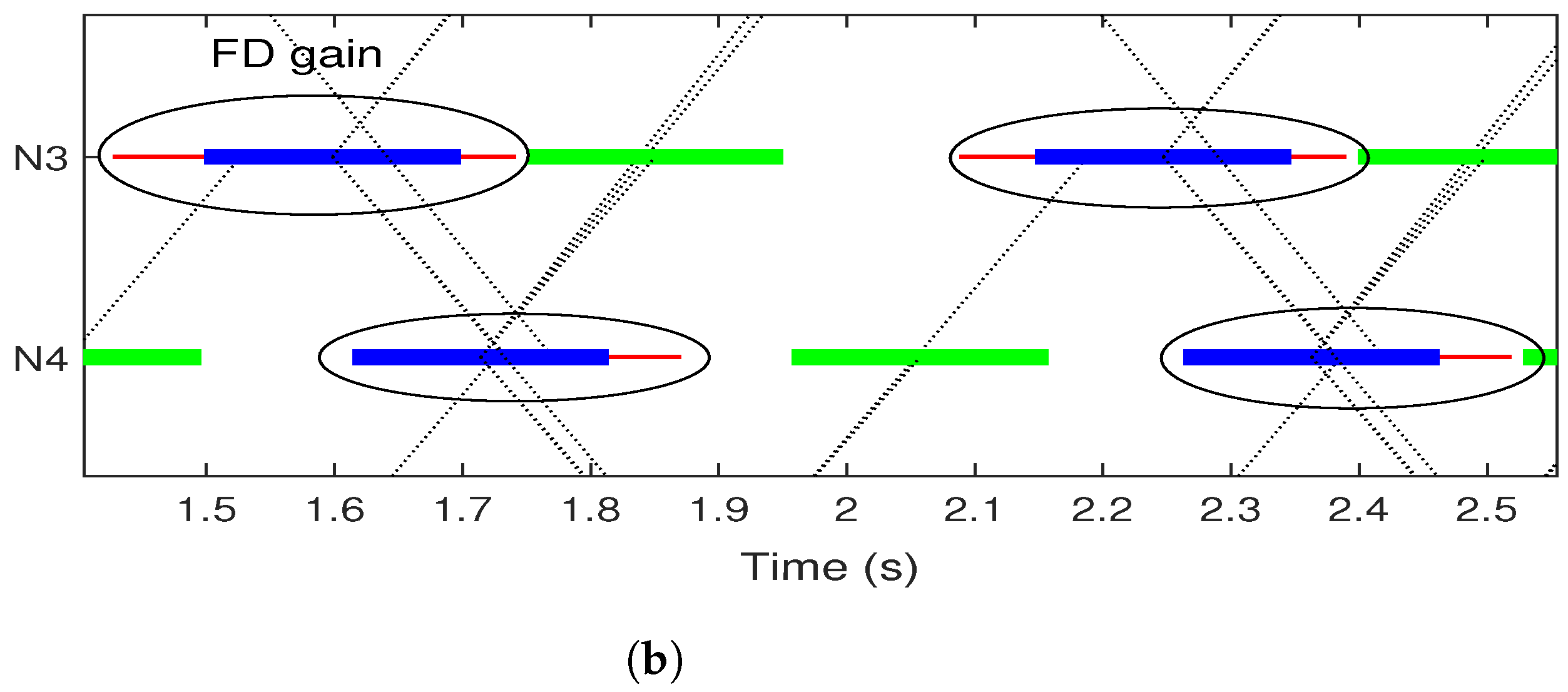
, but excludes the interference reception time, this is because, the FD-LTDA MAC protocol is able to schedule simultaneous transmission and reception of packets. The full-duplex gain (FD gain) is the measure of the transmit delay required for the FD-LTDA MAC protocol to successfully schedule packet transmissions without packet collisions. Examples of FD gain can be found in Figure 3 where N 1 can transmit data packets (D2 and D3) much earlier than it could in the case of LTDA-MAC protocol. Additionally, D2 can be transmitted earlier by N 2 due to the full-duplex capability compared with LTDA-MAC.
The transmission scheduling is based on the timings and these timings are based on the scheduling algorithm which is described below. In order to find the transmission times, as labelled in Figure 3, the following algorithm is used. Extending the 4-nodes network of Figure 3 to the case with N s n transmitting sensor nodes, the FD-LTDA-MAC schedule transmit delays incurred by a node transmitting its own data packet to a node up the chain are represented by a triangular matrix,
T tx FD = T o w n F D [ 1 , 1 ] T f o r w F D [ 1 , 2 ] T f o r w F D [ 1 , N s n ] T o w n F D [ 2 , 2 ] T f o r w F D [ 2 , N s n ] T o w n F D [ N s n , N s n ] ,
where,
T o w n F D [ i , i ] = T t x [ i , i ] τ r p ,
T f o r w F D [ i , j ] = T t x [ i , j ] τ d p ,
T o w n F D [ i , i ] represents the transmit delays incurred by node i for sending its own data packet(s) and T f o r w F D [ i , j ] represents transmit delays for node i to forward node j’s data packet(s) given that ( i < j ) . Furthermore, T t x [ i , i ] and T t x [ i , j ] represent the respective transmit delays for a node sending its own data and relaying data from a node down the chain based on the traditional LTDA-MAC scheme.
Transmission schedules are derived by optimally solving for N s n ( N s n + 1 ) / 2 values in T tx FD and the solution yields a minimum frame duration ( τ frame ( N , T tx FD ) ) with zero packet collisions ( η c o l ( N , T tx FD , τ g ) ), where τ g is the allowable guard interval between scheduled packets and N is a tuple that represents a typical underwater full-duplex chain network topology. The full network topology is defined by an ( N × N ) interference binary matrix, I , propagation delay matrix, T p , REQ and data packet durations, τ r p and τ d p . The interference matrix can be expressed as:
I = I [ 1 , 1 ] I [ 1 , 2 ] I [ 1 , N ] I [ 2 , 1 ] I [ 2 , 2 ] I [ 2 , N ] I [ N , 1 ] I [ N , 2 ] I [ N , N ] ,
where I [ i , j ] = 1 if node i is in interference range of node j, and I [ i , j ] = 0 otherwise. Additionally, the propagation delay from node i to node j is given as T p [ i , j ] .
The FD-LTDA-MAC protocol uses a greedy algorithm to derive collision-free transmission schedules by iterating over transmit delays in T tx FD to check for overlaps in time in any pair of transmit/receive packets at a node, or where a separation between scheduled packets is less than τ g . It compares the data transmission, interference, and reception times to detect a full-duplex transmission, and then forces the algorithm to choose a starting point for the transmit delay search, selecting a local optimal value for it. Moreover, in the case of full-duplex transmission, the initial schedule is modified by removing the allowable separation, τ g , between the REQ packet interference and transmit data packet at a node. This is because, in full-duplex transmission mode, a receive/transmit overlap in time at a node does not count as a collision but a successful transmission, thus, adding τ g becomes unnecessary. Additionally, in evaluating the schedule, the additional delay incurred at a node given full-duplex transmission is τ g . The minimum transmit delay constraint to be imposed on any transmitting node to send its own data packet is given as:
n 1 . . N s n , T m F D [ n , n ] = τ r p + τ g , n < N s n τ g , n = N s n ,
where T m F D [ n , n ] is the minimum transmit delay for a node to send its own data. Similarly, the minimum transmit delay constraint imposed on a node for relaying a data packet up the chain from a node further down the chain is represented as:
n , k 1 . . N s n , k > n , T m F D [ n , k ] = 2 τ p [ n + 1 ] + τ g + τ r p + T t x [ n + 1 , k ] ,
where T m F D [ i , j ] is the minimum transmit delay assigned to node i for transmitting a packet generated by node j and τ p [ i ] is the propagation delay on the ith link between adjacent nodes of the network. This constraint provides for the allowable time for a node to receive a packet while transmitting another data packet. Nonetheless, for a node transmitting its own data packet up the chain and forwarding a data packet received from a node further down the chain in a half-duplex mode will resort to the respective minimum transmit delay [18],
n 1 . . N s n , T m [ n , n ] = τ r p + 2 τ g , n < N s n τ g , n = N s n ,
and
n , k 1 . . N s n , k > n , T m [ n , k ] = 2 ( τ p [ n + 1 ] + τ g ) + τ r p + τ d p + T t x [ n + 1 , k ] .
The FD-LTDA-MAC protocol is described in Algorithm 1. The network instance is firstly created with appropriate τ g and time step, τ s t e p . Then, the initial collision-free schedule is calculated using a large value of transmit delay, T l a r g e . The algorithm then checks for full-duplex transmissions by looking for overlap in time of transmit times, τ t x , and interference time, τ I , among the nodes transmitting their own data packets. It then schedules full-duplex transmission for nodes transmitting own packet(s) using (5). The above process is repeated for relay transmissions, but (6) is used for forwarding the data packets by relay nodes. The features of the FD-LTDA MAC protocol are highlighted as follows:
  • It uses linear constraints to calculate transmit delays for forwarding packets to reflect full-duplex capabilities;
  • To allow the greedy scheduling algorithm utilise the full-duplex based initial starting point that excludes data transmission time and the corresponding propagation delay components from the transmit delay time, as allowed by full-duplex communication;
  • Include full-duplex support in the algorithm to evaluate schedules that are derived for full-duplex transmissions.
Algorithm 1 FD-LTDA-MAC scheduling based on greedy optimisation algorithm
1:
Create N using initial network discovery
2:
Set the desired guard interval and time step τ g and time step τ s t e p
3:
Initialise collision-free schedule using: n , k 1 . . N s n , k n , T t x [ n , k ] = ( N s n n + k ) T l a r g e
4:
for i 1 . . N s n do
5:
    for  n 1 . . ( N s n i + 1 )  do
6:
        Calculate the packet index k = n + i 1
7:
        Calculate τ t x and τ I
8:
        if  τ t x τ I  then
9:
           Calculate T m F D [ n , k ] using (5) if n = k , or (6) if n k
10:
           Initialise Tx delay: T t x F D [ n , k ] = T m F D [ n , k ]
11:
        else
12:
           Calculate T m [ n , k ] using (7) if n = k , or (8) if n k
13:
           Initialise Tx dealy: T t x [ n , k ] = T m [ n , k ]
14:
        end if
15:
        while  η c o l ( N , T tx , τ g ) > 0  do
16:
           Increment Tx delay: T t x [ n , k ] T t x [ n , k ] + τ s t e p
17:
        end while
18:
    end for
19:
end for

3. Simulation Scenarios

3.1. Linear UWA Chain Full-Duplex Network

The full-duplex based underwater acoustic network scenarios with line topology studied here are representative of the subsea asset (pipeline) monitoring scenario depicted in Figure 1. A pipeline is deployed at a depth of 480 m and then connected through a riser to the platform. The network is made up of multiple transmitting sensor nodes and a sink node arranged in line multi-hop fashion, such that each node connects to a node one hop closer to the sink node and to a node one hop further down the chain. The sink node sends REQ packets to the transmitting nodes. The transmitting nodes propagate the REQ packets down the chain to the last node. The transmitting sensor nodes either send their own packet up the chain or forward packet(s) up the chain after receiving them from a node further down the chain upon receiving an REQ packet.
The nodes in the chain network topology are able to operate in full-duplex fashion. Figure 4 depicts full-duplex communication in a underwater chain network, where the relay nodes are able to transmit and receive simultaneously in time and frequency. This allows the nodes to send and receive REQ or data packets in-band thereby potentially improving spectrum reuse.
The scenarios are categorised as small, medium and large scale in accordance with the pipeline length. In each of the scenarios, the maximum sea depth is considered to be 500 m. Different scenarios are described in Table 1. The scenarios range from very small networks with few nodes to long pipelines comprising many nodes. For all the scenarios, sensor nodes are spread across the length of the pipeline at equidistant points of 1 km/2 km based on the acoustic modem range. An acoustic modem range of 1 km is considered to be a reliable range and 2 km approaching the range limit. The nano-modem [25] assumed in this work has the advantage of low cost, which makes it feasible to consider deploying a large number of monitoring devices. Another benefit for considering short range acoustic communication is the provision of regular monitoring points for the detection of problems such as leaks and movement of pipelines.

3.1.1. Small Scale Scenarios

The small scale scenarios are generally denoted as Small_L_H, where L and H are the pipeline length and the number of hops in the network, respectively. In the small scale scenarios, L varies between 2 and 20 km while, H varies from 2 to 20 hops. 2, 10 and 20 km pipelines configured with 2, 4, 10 and 20 hops are considered for the small scale scenario.

3.1.2. Medium Scale Scenarios

Similarly, a medium scale scenarios are denoted by Medium_L_H, where L ranges from 50 to 100 km and H ranges from 25 to 100 hops. In the case presented here, pipeline lengths of 50 km and 100 km configured with 25, 50 and 100 hops are considered.

3.1.3. Large Scale Scenarios

The large scale scenarios represented as Large_L_H have values of L and H between 200 and 1000 km, and 100 to 1000 hops, respectively.
The transmission range is important for the deployment of underwater acoustic networks. It influences energy efficiency, network connectivity and network reliability. The transmission range is determined by the acoustic modem assumed [27]. For practical applications such as underwater pipeline monitoring, regular sensing is required.
Typically, there may be a need to communicate over longer ranges, nano-modems [25] could be used to provide this capability. Although, other acoustic modems with higher ranges (300 m–10 km), data rates (up to 62,500 bps) and transmit power (up to 80 W), such as Evologics, DiveNET, LinkQuest [28,29,30], etc., are alternatives, however, there is need to consider a trade-off between performance and cost effectiveness in terms of scalability for large scale deployment. In other words, low powered modems exhibit lower power consumption which improves energy efficiency with the appropriate protocols to extend network lifetime.

3.2. Simulation Set-Up

3.2.1. Channel Model

Although there are several available propagation models, such as ray tracing, normal mode, parabolic equation, wavenumber integration, energy flux, finite difference, and finite element models [31], the acoustic propagation model employed is based on the BELLHOP [26] beam tracing method described in [32]. The choice is influenced by computational cost and model efficiency with respect to topology and application scenarios. Spatially varying local environment can influence underwater acoustic propagation. In order to accurately provide a representation of acoustic propagation, the following environmental variables that serve as the model input data are considered: bathymetry, sea surface, ambient noise power, and sound speed profile, source, and receiver locations.
The bathymetry (characteristics of the sea bed) influences the propagation pattern of the sound wave, in order to provide an accurate multi-path propagation pattern, this paper employed a generic bathymetry model presented in [32] where small-scale variations are described by the sinusoidal shape bathymetry [32,33,34] represented by the following model:
z ( x ) = R ( x ) × z m a x 2 sin π 2 + 2 π x L h i l l + 1 ,
where z ( x ) is the random elevation of the hills along horizontal range, x, z m a x represents the maximum hill elevation, and the length of single hill is L h i l l , while, R ( x ) is a uniform random number between 0 and 1. For the acoustic propagation model assumed in this work, z m a x is set to 10 and a generic sea bottom layer represents sand-silt with 1 g cm 3 density [26,31]; the generated bathymetry is shown in Figure 5.
The Pierson–Moskowitz spectral model for fully developed wind seas [34,35] is used to obtain realisations of the random surface waves. Additionally, Gaussian beam spreading model is utilised to estimate the total intensity at the receiver. In order to compute the total wideband received signal power, the BELLHOP based ray tracing is used to compute the channel impulse response comprising of attenuation, phase and delay of multi-path components. A well established ambient noise model [36] is used to calculate acoustic noise at the receiver with the power spectral density
N a m b i e n t ( f ) = l o g N t ( f ) + N s ( f ) + N w ( f ) + N t h ( f ) .
The components in (10) are described as
N t ( f ) = 17 30 l o g f ,
N s ( f ) = 40 + 20 ( s 0.5 ) + 26 l o g f 60 l o g ( f + 0.03 ) ,
N w ( f ) = 50 + 7.5 w 1 2 + 20 l o g f 40 l o g ( f + 0.4 ) ,
N t h ( f ) = 15 + 20 l o g f ,
where N t , N s , N w and N t h are the turbulence, shipping, wind, and thermal noise components, respectively. The shipping activity factor, s is set between 0 and 1, representing low and high activity, respectively, and the wind speed w is given in m s 1 .
The SNR is computed as
SNR = G P tx f min f max N ambient ( f ) d f ,
where G P tx is the received signal power, G is the channel gain, P tx is the transmitted signal power and N ambient ( f ) is the noise PSD between the lower and upper limit of the communication frequency band of the communication system. Figure 6 shows the SNR as a function of range and depth for the source at 480 m depth and source level of 170 dB re µ Pa at 1 m, 24 KHz center frequency and 7.2 KHz bandwidth. Assuming source placed at 480 m, and a minimum SNR of 0 dB is required to decode a signal (transmitted at 170 dB re 1 μ Pa at 1 m) at the receiver, then, the source-receiver range can be approximated as 3.5 km as can be seen in Figure 6. In this case, we neglect internal receiver noise characteristics and residual self-interference in the case of full-duplex nodes.

3.2.2. Simulation Model

Statistical channel models of the scenarios described above are created using the BELLHOP beam tracing method, as described above. To achieve this, an array of the node positions for 1 − N s n hop distance ( N s n ranges from 2 to 1000 depending on the scenario) is created with the first node as the sink node plus n other transmitting nodes. The N s n transmitting nodes and the sink node are arranged as described in Section 3.1.
The statistical channel model uses random node positions set to be within 10 m sphere around of N s n + 1 random displacements in both source and receiver positions to generate underwater acoustic channel realisations for every possible hop distance. Then channel gain, delay, and delay spread for every link in the network scenario is used to generate a full network model based on a corresponding lookup table.
Thereafter, a binary interference matrix ( N × N ), I is generated such that I [ i , j ] = 0 if i = j (i.e., not interfering nodes) or I [ i , j ] = 1 if i j with SNR ≥ 0 dB (i.e., the interfering nodes). The FD-LTDA-MAC schedule is derived by loading the pre-simulated BELLHOP channel data of the node set (1–50) on to the algorithm that runs the FD-LTDA-MAC. The key simulation parameters are summarised in Table 1.

4. Results and Discussion

Here, we consider simulation results of FD-LTDA-MAC, LTDA-MAC, and LTDA-MAC with FD enabled nodes. The comparison is performed using the frame duration, i.e., the frame duration is time taken to complete transmitting a frame from the beginning of the frame to end of the frame. Where frame is a network digital unit that defines a segment of data on a network or communication link in data-link or physical layer usually consisting of preamble, destination, and sources addresses, data payload, and error-checking information. It is important, because it defines the rate at which each node can send a new sensor reading. It is also important to state here that the frame duration is equal to the inverse of the monitoring rate, in other words, the shorter the frame duration, the higher the monitoring rate.
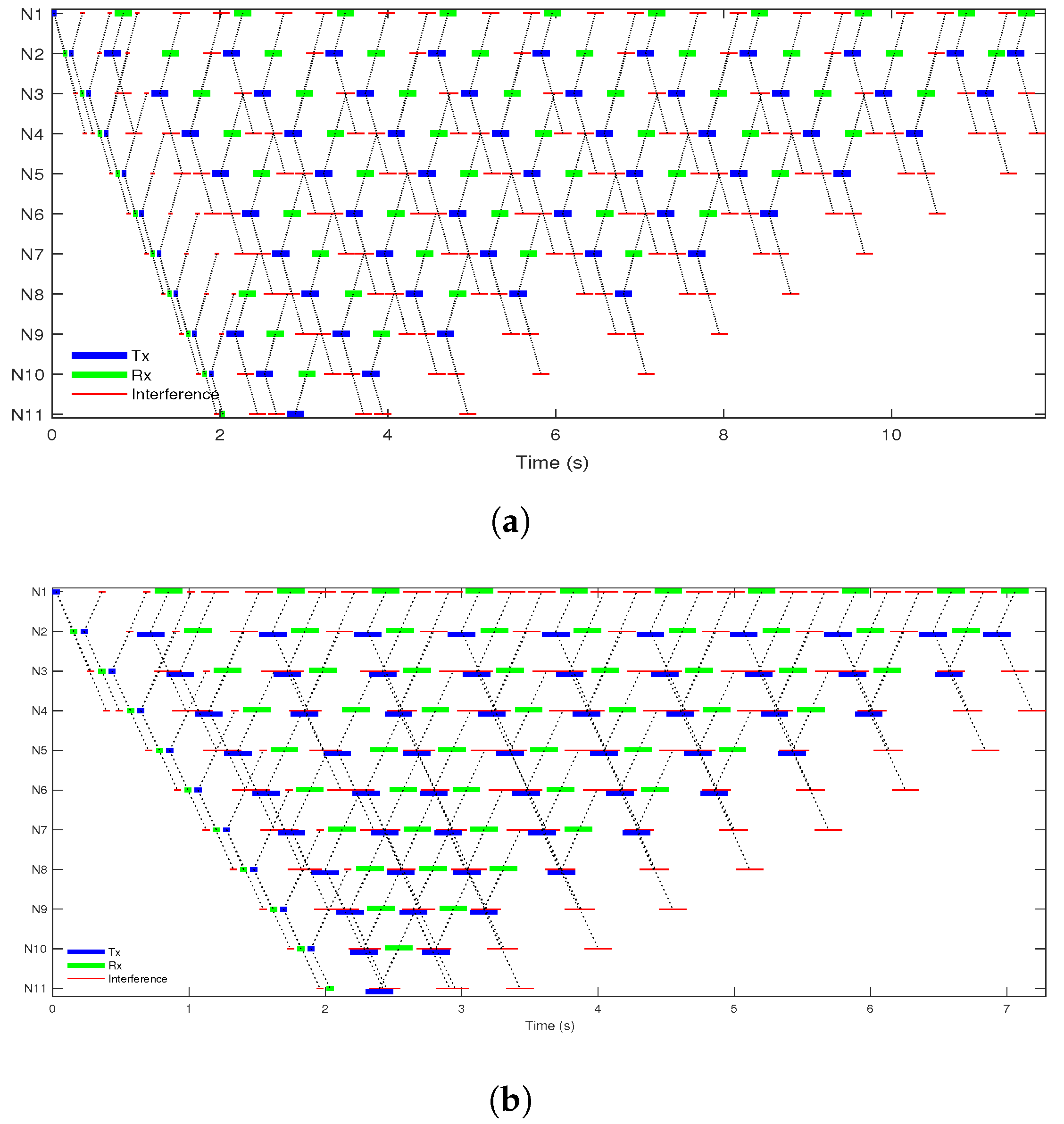
Simulated MAC schedules for FD-LTDA-MAC and LTDA-MAC for a 10-hop 2 km pipeline are presented in Figure 7. It shows packet schedules for data transmission and reception in the presence of interference. FD-LTDA-MAC shows, a 44% reduction in the frame duration and packets are still correctly received at the desired destination nodes despite the overlap in time between the transmit and interference packets compared to the LTDA-MAC with HD enabled nodes as can be observed in Figure 7b. This also provides a 10% compression of frame duration against LTDA-MAC with FD enabled nodes presented in [24]. This compression in the frame duration given correct reception of packets in the presence of overlap in time is made possible by the ability of the FD-LTDA-MAC to fully exploit spectrum reuse. In contrast, Figure 7a shows a longer frame duration because the half-duplex nodes do not allow simultaneous in-band transmission and LTDA-MAC lacks the capability to handle full-duplex transmissions. As a result, frame durations and end-to-end packet delays are shorter with the FD-LTDA-MAC protocol compared to the LTDA-MAC protocol with HD enabled nodes and LTDA-MAC protocol with FD enabled nodes scenarios.
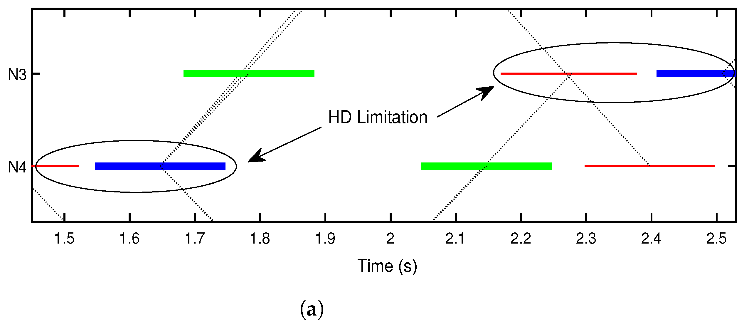
Figure 8a,b show sections of Figure 7a,b representing a time interval of 1.4–2.5 s involving N3 and N4 nodes. It can be seen that the FD-LTDA-MAC protocol exploits spatial re-use better by scheduling simultaneous in-band transmission and reception, which reduces transmit delays and compresses the overall frame duration, as can be seen as FD gain in Figure 5b. The LTDA-MAC protocol has the limitation of this capability as shown in Figure 5a, this causes waste of resources (time), thus, resulting in longer transmit delays.
The following subsections discuss the impact of the frame duration enhancement on the monitoring rate and end-to-end packet delays.

4.1. Small Scale Scenarios: 2, 10, and 20 km Pipelines

The simulation results for small scale scenarios considering short pipelines of few kilometres (2, 10 and 20 km) are presented here. It is important to firstly consider short pipelines with a different number of hops in order to understand the performance of the FD-LTDA-MAC protocol in simple situations where there is a limited opportunity for spatial reuse.
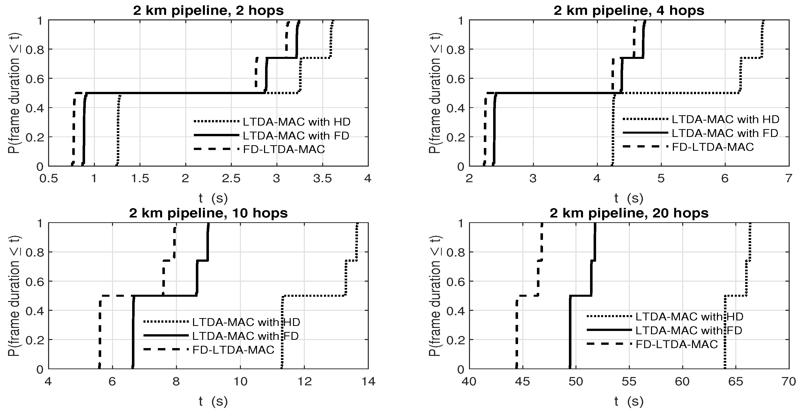
The cumulative distributive function (cdf) plot of frame durations for FD-LTDA-MAC, LTDA-MAC, and LTDA-MAC in FD protocols in small scale scenarios are shown in Figure 9, Figure 10 and Figure 11. The results for a 2 km pipeline configured with 2, 4, 10, and 20 hops can be seen in Figure 9, which shows that FD-LTDA-MAC can achieve shorter frame durations compared to the LTDA-MAC and LTDA-MAC with FD protocols. The frame duration is reduced on average by 29% and 9% against LTDA-MAC and LTDA-MAC in FD, respectively. Hence, this capability provides better packet schedules which translates into improvement in network throughput even with limited opportunity for spatial reuse.
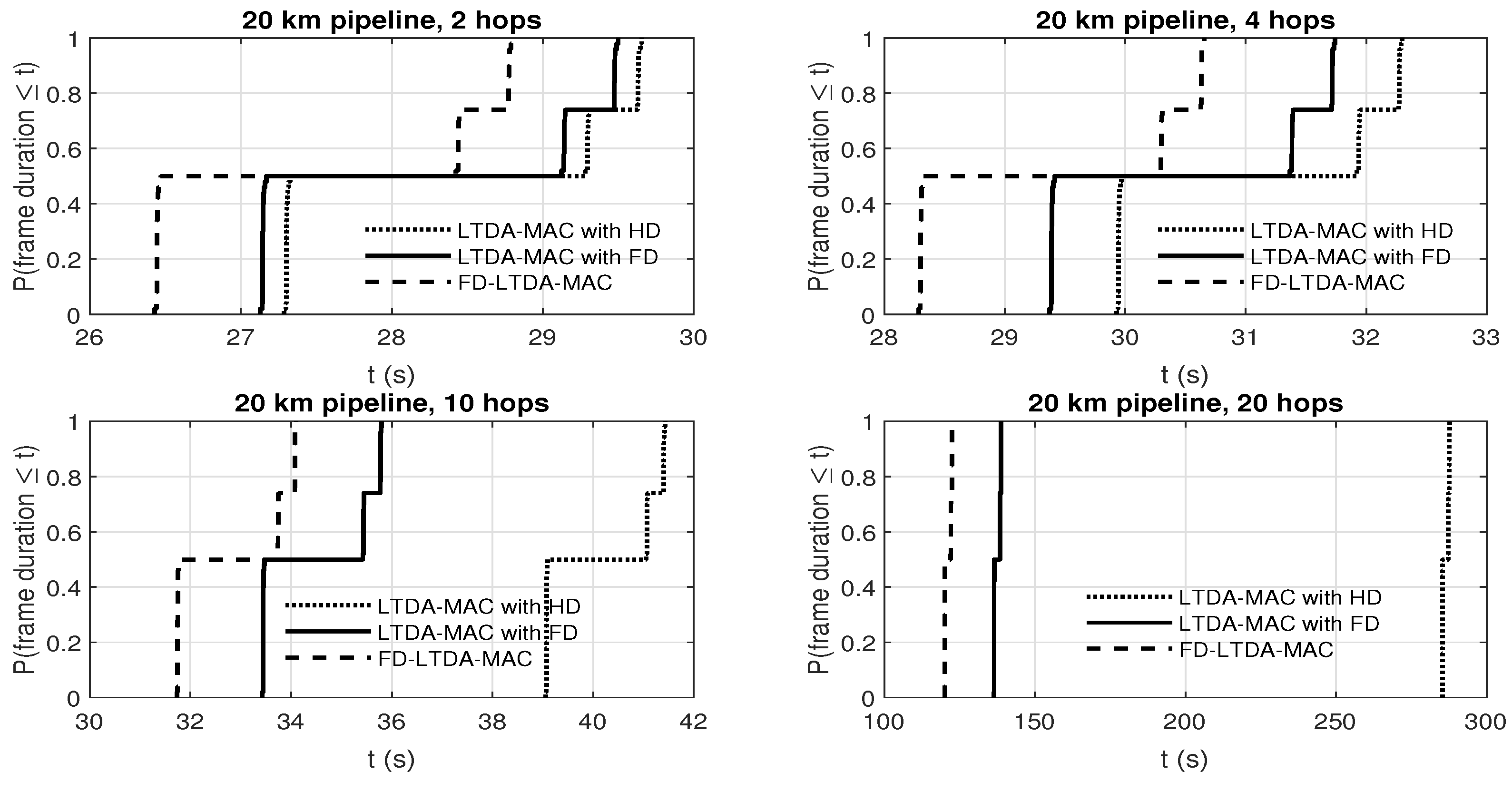
The frame durations obtained for 10 km and 20 km pipelines as shown in Figure 10 and Figure 11 demonstrate a more significant performance improvement compared with 2 km pipeline scenarios. The FD-LTDA-MAC shortens the frame duration by 64% against LTDA-MAC protocol, whereas LTDA-MAC in FD improves by 53% against LTDA-MAC protocol. The significant improvement achieved by FD based protocols is because the search algorithm is able to better exploit longer pipelines.

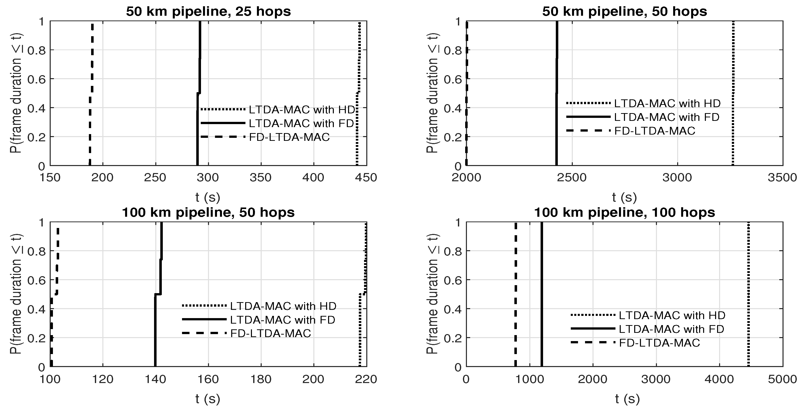
4.2. Medium Scale Scenarios: 50 and 100 km Pipelines

In practice, pipelines span several hundreds to thousands of kilometres, such as the Langeled pipeline in the North Sea measuring about 1200 km [6], and the 7200 km long pipelines under the gulf of Mexico [37]. For underwater oil and gas pipeline monitoring, applications such as leak detection require timely sensor readings at certain intervals and demand a high resolution of sensed data. This motivates studying the deployment of FD-LTDA-MAC protocol in medium scale scenarios, so as to understand intermediate performance improvement and to track the improvement by understanding where the optimum performance enhancement lies. The frame durations derived by FD-LTDA-MAC for 50 and 100 km pipelines with 25 and 50 hop configurations as seen in Figure 12 are of the range 104 s to 779 s, with the lower bound corresponding to the 25 hop case and the upper bound the 100 hop case. In comparison with the frame durations ranging from 218 s to 4457 s and 144 s to 1192 s derived by LTDA-MAC and LTDA-MAC over FD nodes, respectively, there is significant reduction in the frame duration. The performance improvement as a ratio can be approximated as 1:1.4:2 for the lower bound and 1:2:6 for the upper bound. Thus, LTDA-MAC performs poorly in medium scale scenarios compared to FD-LTDA-MAC. This means FD-LTDA-MAC can achieve higher monitoring rates compared to LTDA-MAC and LTDA-MAC in FD.
Furthermore, the 25 and 50 hop scenarios for 50 and 100 km pipelines, respectively, show that more regular sensing along a pipeline can be achieved by FD-LTDA-MAC protocol with a 2 km sensing range. The results also indicate that the greedy optimisation algorithm in FD-LTDA-MAC can achieve a better solution in longer pipelines with full-duplex capability. This is the reason why performance improvement achieved in medium scale scenarios is superior compared with small scale scenarios.

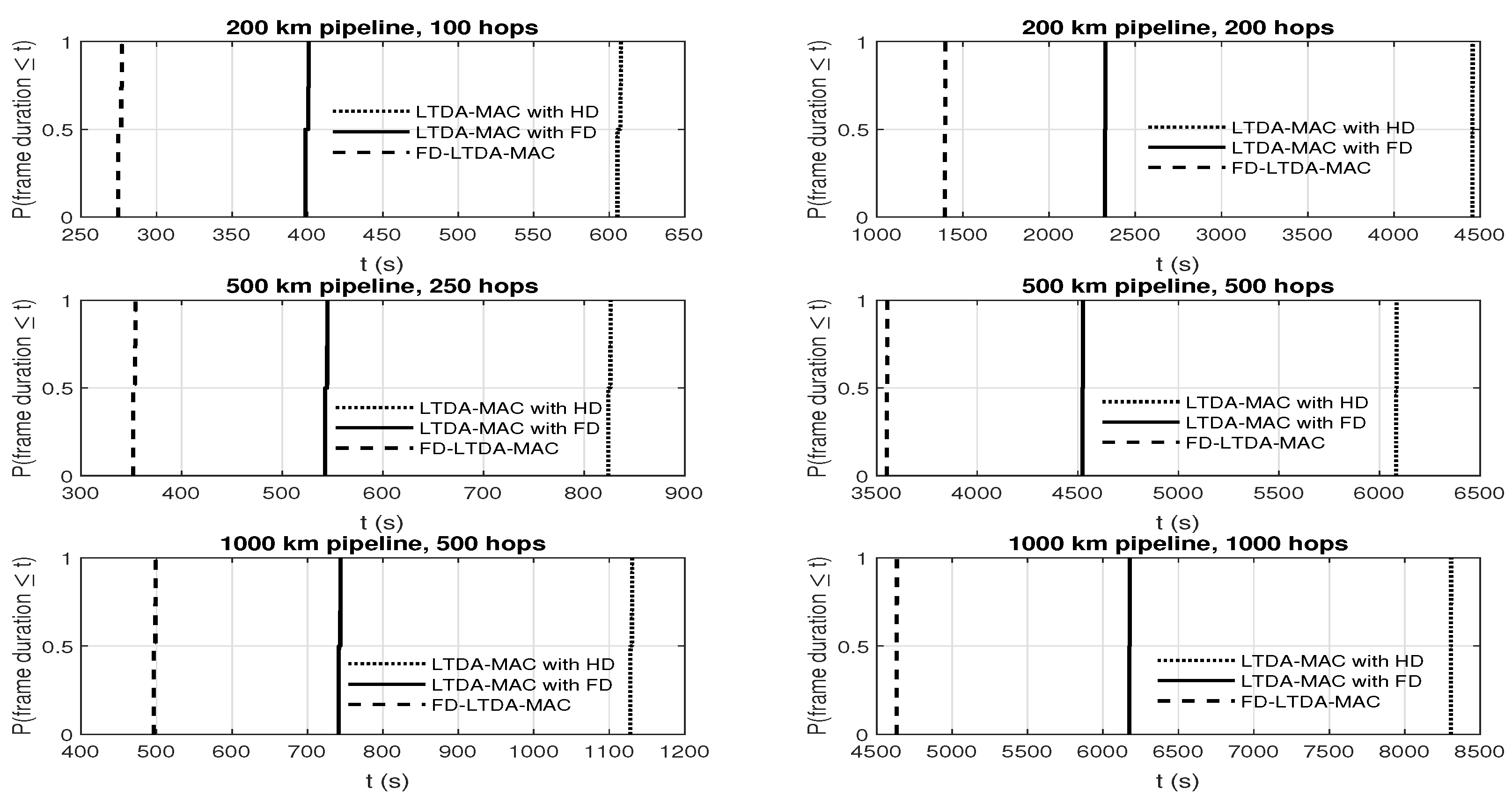
4.3. Large Scale Scenarios: 200, 500, and 1000 km Pipelines

Large scale network scenarios include pipelines that span from 200 km to 1000 km. The achieved frame durations are presented in Figure 13. The results show that monitoring intervals for LTDA-MAC and LTDA-MAC over FD are low as frame durations are very long (607 s to 4457 s and 404 s to 2326 s for LTDA-MAC and LTDA-MAC over FD, respectively). From Figure 10, we can see that FD-LTDA-MAC compresses the frame durations to about 276 s–1399 s, thus providing much higher monitoring rates. Here, LTDA-MAC for the 1000 km pipeline may require up to 8000 seconds which may be impractical for some pipeline monitoring applications. Providing more regular monitoring for these longer pipelines may require high power and longer range costly acoustic modems, however, FD-LTDA-MAC on scenarios configured with 2 km sensing range acoustic modems significantly reduce the monitoring rate to more acceptable values, such as 498 s for a 500-hop 1000 km pipeline scenario. It is thus important to state that there should be a need to monitor quite regularly along the pipeline, this is the main reason for more hops which is backed up by the low cost modem making a greater number of devices a reasonable prospect.

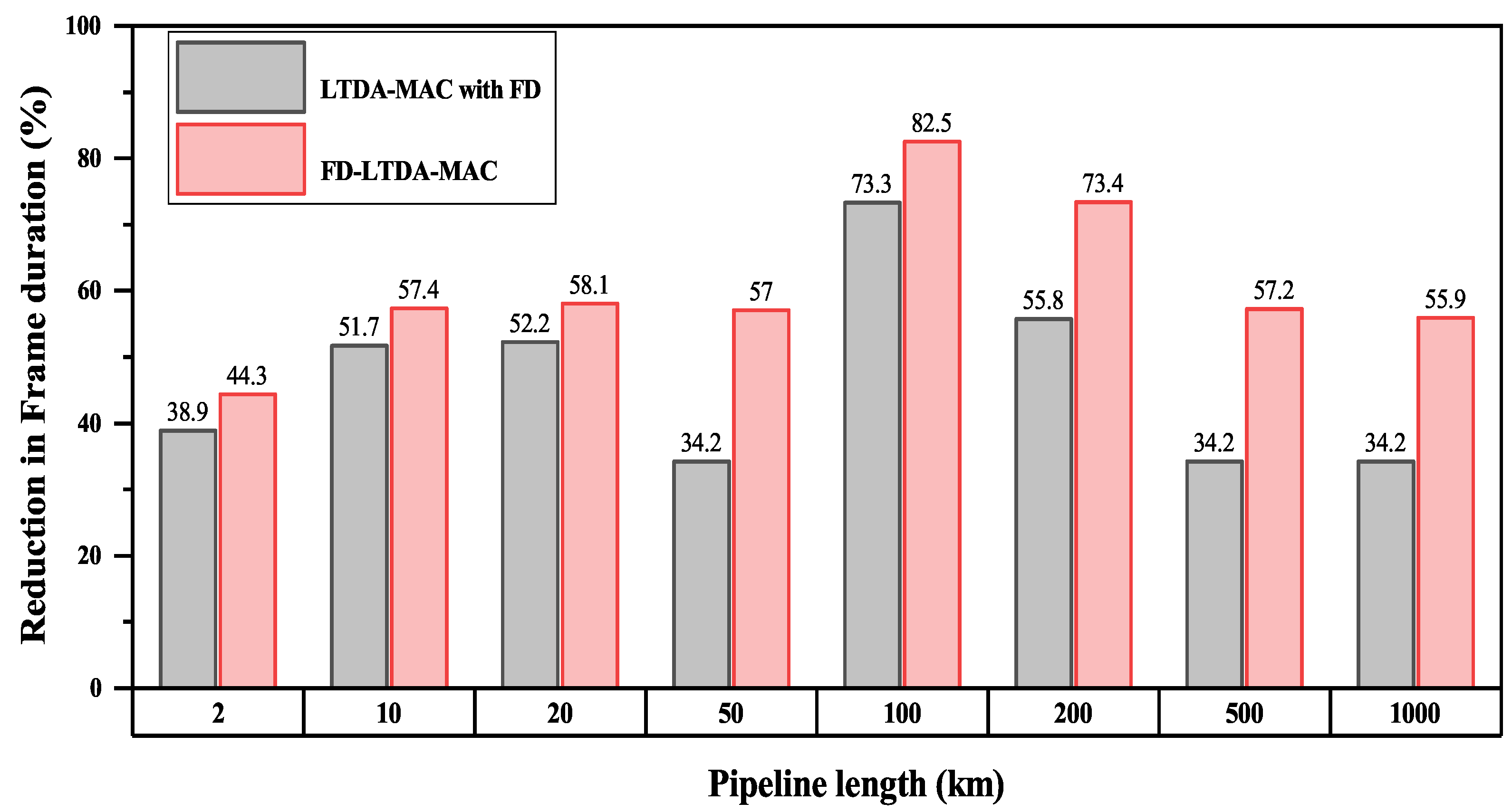
4.4. Percentage Reduction in Frame Duration

The percentage reduction in frame duration across the pipeline length for both LTDA-MAC with FD nodes and FD-LTDA-MAC compared to LTDA-MAC with half-duplex nodes is shown in Figure 14. Although the monitoring rate improves across the pipeline length, the FD-LTDA-MAC shows higher percentage reduction in frame duration compared with LTDA-MAC and LTDA-MAC in FD. This is because the FD-LTDA-MAC is able to better exploit the spatial re-use. Consequently, FD-LTDA-MAC has better prospect with scalability than LTDA-MAC and LTDA-MAC in FD.

5. Conclusions

This paper proposes the FD-LTDA-MAC protocol, a new protocol which builds on LTDA-MAC but it provides efficient packet schedules for full-duplex based underwater acoustic chain network scenarios. This protocol significantly improves spatial re-use on a time shared channel but fully exploits full-duplex operation to compress frame durations especially for the longer pipelines spanning thousands of kilometres to improve the monitoring. The FD-LTDA-MAC protocol produces a better packet schedule for underwater acoustic chain network scenarios. Linear constraints in FD-LTDA-MAC allow for the calculation of transmit delays for forwarding packets to reflect full-duplex capabilities, extension to the greedy scheduling algorithm to utilise full-duplex optimised starting point for transmit delay search and modify the initial schedule and evaluation algorithms to accommodate full-duplex capability. The advantage of spectrum re-usability of FD-LTDA-MAC is leveraged by the full-duplex communication mechanisms to deal with long propagation delay and interference patterns to provide a more efficient packet schedules, which, in turn, provides greater network throughput performance for the longer pipeline scenarios. Results that are based on simulation of small scale (2 km, 10 km, and 20 km), medium scale (50 km and 100 km) and large scale (200 km, 500 km, and 1000 km) scenarios show that FD-LTDA-MAC achieves a performance improvement of 44%, 83% and 56% in small, medium, and large scale scenarios, respectively, compared to LTDA-MAC protocol. Useful further research includes the use of other optimisation algorithms in a bid to further shorten the frame durations produced by FD-LTDA-MAC. Additionally, redundancy in the links will be explored to solve the problem of failing nodes.

Author Contributions

Conceptualisation, A.A., N.M. and P.D.M.; methodology, A.A., P.D.M., N.M. and Y.Z.; software, A.A. and N.M.; validation, A.A., P.D.M., N.M. and Y.Z.; formal analysis, A.A. and N.M.; investigation, A.A., N.M., P.D.M. and Y.Z.; writing—original draft preparation, A.A.; writing—review and editing, A.A., P.D.M., N.M. and Y.Z.; visualisation, A.A.; supervision, P.D.M., Y.Z. and N.M.; project administration, P.D.M.; funding acquisition, A.A., P.D.M. and Y.Z. All authors have read and agreed to the published version of the manuscript.

Funding

This research was funded by Petroleum trust Development Fund (PTDF).

Institutional Review Board Statement

Not applicable.

Informed Consent Statement

Not applicable.

Acknowledgments

The work has been supported by the Engineering and Physical Sciences Research Council (EPSRC) through [grant numbers: EP/V009591/1, EP/R003297/1 and EP/P017975/1].

Conflicts of Interest

The authors declare no conflict of interest.

References

  1. Heidemann, J.; Ye, W.; Wills, J.; Syed, A.; Li, Y. Research challenges and applications for underwater sensor networking. In Proceedings of the IEEE Wireless Communications and Networking Conference, Las Vegas, NV, USA, 3–6 April 2006; pp. 228–235. [Google Scholar]
  2. Luiz, F.M.V.; David, P.; Viana, S.S. HydroNode: An Underwater Sensor Node Prototype for Monitoring Hydroelectric Reservoirs. In Proceedings of the WUWNET, Los Angeles, CA, USA, 5–6 November 2012; pp. 1–2. [Google Scholar]
  3. Thi-Tham, N.; Yoon, S. ARS: An Adaptive Retransmission Scheme for Contention-Based MAC Protocols in Underwater Acoustic Sensor Networks. Int. J. Distrib. Sens. Netw. 2015, 11, 826263. [Google Scholar]
  4. Murad, M.; Sheikh, A.A.; Manzoor, M.A.; Felemban, E.; Qaisar, S. A Survey on Current Underwater Acoustic Sensor Network Applications. Int. J. Comput. Theory Eng. 2015, 7, 51–56. [Google Scholar] [CrossRef] [Green Version]
  5. Esmaiel, H.; Jiang, D. Multicarrier Communication for Underwater Acoustic Channel. Int. J. Commun. Netw. Syst. Sci. 2013, 6, 361–376. [Google Scholar]
  6. Mohamed, N.; Jawhar, I.; Al-Jaroodi, J.; Zhang, L. Monitoring Underwater Pipelines Using Sensor Networks. In Proceedings of the IEEE International Conference on High Performance Computing and Communications (HPCC), Melbourne, VIC, Australia, 1–3 September 2010; pp. 346–353. [Google Scholar] [CrossRef]
  7. Peach, C.; Yarali, A. An overview of Underwater Sensor Networks. In Proceedings of the International Conference on Wireless and Mobile Communications, Nice, France, 21–26 July 2013; pp. 31–36. [Google Scholar]
  8. Akyildiz, I.F.; Pompili, D.; Melodia, T. Underwater Acoustic Sensor Networks: Research challenges. Ad. Hoc. Netw. 2005, 3, 257–279. [Google Scholar] [CrossRef]
  9. Heidemann, J.; Stojanovic, M.; Zorzi, M. Underwater sensor networks: Applications, advances and challenges. Philos. Trans. R. Soc. 2012, 370, 158–175. [Google Scholar] [CrossRef]
  10. Jin, L.; Huang, D.D. A slotted CSMA based reinforcement learning approach for extending the lifetime of underwater acoustic wireless sensor networks. J. Comput. Commun. 2013, 36, 1094–1099. [Google Scholar] [CrossRef]
  11. Morozs, N.; Mitchell, P.D.; Zakharov, Y. Linear TDA-MAC: Unsynchronized Scheduling in Linear Underwater Acoustic Sensor Networks. IEEE Netw. Lett. 2019, 1, 120–123. [Google Scholar] [CrossRef]
  12. Akyildiz, I.F.; Pompili, D.; Melodia, T. Challenges for efficient communication in Underwater Acoustic Sensor Networks. ACM Sigbed Rev. 2004, 1, 3–8. [Google Scholar] [CrossRef]
  13. Jiang, Z. Underwater Acoustic Networks—Issues and Solutions. Int. J. Intell. Control Syst. 2008, 13, 152–161. [Google Scholar]
  14. Fullmer, C.; Garcia-Luna-Aceves, J. Floor Acquisition Multiple Access (FAMA) for Packet-radio Networks. SIGCOMM Comput. Commun. Rev. 2000, 25, 262–273. [Google Scholar] [CrossRef]
  15. Molins, M.; Stojanovic, M. Slotted FAMA: A MAC protocol for underwater acoustic networks. In Proceedings of the OCEANS, Singapore, 16–19 May 2006; pp. 16–22. [Google Scholar]
  16. Xie, P.; Cui, J. R-MAC: An Energy-Efficient MAC Protocol for Underwater Sensor Networks. In Proceedings of the International Conference on Wireless Algorithms, Systems and Applications, Chicago, IL, USA, 1–3 August 2007; pp. 187–196. [Google Scholar]
  17. Han, S.; Noh, Y.; Lee, U.; Gerla, M. M-FAMA: A multi-session MAC protocol for reliable underwater acoustic streams. In Proceedings of the INFOCOM, Turin, Italy, 14–19 April 2013; pp. 665–673. [Google Scholar]
  18. Morozs, N.; Mitchell, P.D.; Zakharov, Y. LTDA-MAC v2.0: Topology-Aware Unsynchronized Scheduling in Linear Multi-Hop UWA Networks. Network 2021, 1, 2–10. [Google Scholar] [CrossRef]
  19. Song, L.; Wichman, R.; Li, Y.; Han, Z. Full-Duplex Communications and Networks; Cambridge University Press: Cambridge, UK, 2017. [Google Scholar] [CrossRef]
  20. Shen, L.; Henson, B.; Zakharov, Y.; Mitchell, P. Digital Self-Interference Cancellation for Full-Duplex Underwater Acoustic Systems. IEEE Trans. Circuits Syst. II Express Briefs 2019, 67, 192–196. [Google Scholar] [CrossRef] [Green Version]
  21. Qu, F.; Yang, H.; Yu, G.; Yang, L. In-band full-duplex communications for underwater acoustic networks. IEEE Netw. 2017, 31, 59–65. [Google Scholar] [CrossRef]
  22. Gibson, J.; Larraza, A.; Rice, J.; Smith, K.; Xie, G. On the Impacts and Benefits of Implementing Full-Duplex Communications Links in an Underwater Acoustic Network. 2002. Available online: https://apps.dtic.mil/sti/pdfs/ADA478925.pdf (accessed on 3 November 2021).
  23. Kim, D.; Lee, H.; Hong, D. A Survey of In-Band Full-Duplex Transmission: From the Perspective of PHY and MAC Layers. IEEE Commun. Surv. Tutor. 2015, 17, 2017–2046. [Google Scholar] [CrossRef]
  24. Ahmed, A.; Mitchell, P.D.; Zakharov, Y.; Morozs, N. Performance of Linear TDA-MAC in Full-Duplex Underwater Acoustic Chain Networks. In Proceedings of the 7th IEEE World Forum on the Internet of Things, New Orleans, LA, USA, 14 June–31 July 2021. [Google Scholar]
  25. Renner, B.C.; Heitmann, J.; Steinmetz, F. AHOI: Inexpensive, Low-Power Communication and Localization for Underwater Sensor Networks and µAUVs. ACM Trans. Sen. Netw. 2020, 16, 1550–4859. [Google Scholar] [CrossRef] [Green Version]
  26. Porter, M.B. The BELLHOP Mannual and User’s Guide: Preliminary Draft; Heat, Light, and Sound Research, Inc.: La Jolla, CA, USA, 2011. [Google Scholar]
  27. Gao, M.; Foh, C.H.; Cai, J. On the Selection of Transmission Range in Underwater Acoustic Sensor Networks. Sensors 2012, 12, 4715–4729. [Google Scholar] [CrossRef] [Green Version]
  28. Evologics: S2C Underwater Acoustic Modems. Available online: https://evologics.de/acoustic-modems (accessed on 10 July 2021).
  29. DiveNET: Acoustic Modems. Available online: https://www.divenetgps.com (accessed on 10 July 2021).
  30. LinkQuest: SoundLink Underwater Acoustic Modems. Available online: https://www.link-quest.com (accessed on 10 July 2021).
  31. Jensen, F.; Kuperman, W.; Porter, M.; Schmidt, H. Computational Ocean Acoustics; Springer: New York, NY, USA, 2011. [Google Scholar] [CrossRef]
  32. Morozs, N.; Gorma, W.; Henson, B.T.; Shen, L.; Mitchell, P.D.; Zakharov, Y.V. Channel Modeling for Underwater Acoustic Network Simulation. IEEE Access 2020, 8, 136151–136175. [Google Scholar] [CrossRef]
  33. Belibassakis, K. A coupled-mode model for the scattering of water waves by shearing currents in variable bathymetry. J. Fluid Mech. 2007, 578, 413–434. [Google Scholar] [CrossRef] [Green Version]
  34. Glenn, S.M.; Crowley, M.F.; Haidvogel, D.B.; Song, Y.T. Underwater observatory captures coastal upwelling events off New Jersey. Eos Trans. Am. Geophys. Union 1996, 77, 233–236. [Google Scholar] [CrossRef]
  35. Mobley, C.; Boss, E.; Roesler, C. Ocean Optics Web Book. The Pierson–Moskowitz Omnidirectional Gravity Wave Spectrum. Online.. 2017. Available online: https://oceanopticsbook.info/view/surfaces/level-2/wave-variance-spectra-examples (accessed on 3 November 2021).
  36. Stojanovic, M. On the Relationship Between Capacity and Distance in an Underwater Acoustic Channel. ACM Int. Workshop Underw. Netw. (WUWNet) 2007, 11, 34–43. [Google Scholar] [CrossRef]
  37. Ho, M.; El-Borgi, S.; Patil, D.; Song, G. Inspection and monitoring systems subsea pipelines: A review paper. Struct. Health Monit. 2020, 19, 606–645. [Google Scholar] [CrossRef] [Green Version]
Figure 1. A typical linear UASN subsea asset monitoring scenario (Taken with permission from [11]. Copyright 2019 IEEE Networking Letters.).
Applsci 11 10967 g001
Figure 2. Multi-hop chain FDR network.
Applsci 11 10967 g002
Figure 3. FD-LTDA-MAC schedules in a three-hop network.
Applsci 11 10967 g003
Figure 4. FD-based linear UASN network scenario.
Applsci 11 10967 g004
Figure 5. Sinusoidal bathymetry with 200 m long hills and random hill height.
Applsci 11 10967 g005
Figure 6. SNR as a function of range and depth for the source at 480 m depth, source level: 170 dB re 1 μ Pa at 1 m, 24 KHz centre frequency and 7.2 KHz bandwidth.
Applsci 11 10967 g006
Figure 7. Simulated MAC schedules for the 2 km 10-hop scenario. Tx: Transmission, Rx: Reception. (a) LTDA-MAC [11]. (b) FD-LTDA-MAC.
Applsci 11 10967 g007
Figure 8. Zoomed in sections of Figure 7a,b. (a) LTDA-MAC. (b) FD-LTDA-MAC.
Applsci 11 10967 g008aApplsci 11 10967 g008b
Figure 9. Frame duration cdfs of LTDA-MAC with HD nodes, LTDA-MAC with FD nodes, and FD-LTDA-MAC for a 2 km pipeline.
Applsci 11 10967 g009
Figure 10. Frame duration cdfs of LTDA-MAC with HD nodes, LTDA-MAC with FD nodes, and FD-LTDA-MAC for a 10 km pipeline.
Applsci 11 10967 g010
Figure 11. Frame duration cdfs of LTDA-MAC with HD nodes, LTDA-MAC with FD nodes, and FD-LTDA-MAC for a 20 km pipeline.
Applsci 11 10967 g011
Figure 12. Frame duration cdfs of LTDA-MAC with HD nodes, LTDA-MAC with FD nodes and FD-LTDA-MAC for medium scale scenarios.
Applsci 11 10967 g012
Figure 13. Frame duration cdfs of LTDA-MAC with HD nodes, LTDA-MAC with FD nodes, and FD-LTDA-MAC for large scale scenarios.
Applsci 11 10967 g013
Figure 14. Percentage reduction in the Frame duration across pipeline scenarios.
Applsci 11 10967 g014
Table 1. Simulation parameters.
ParameterValue
Transmit power (Small scale scenarios)140 dB re µ Pa2m2
Transmit power (Medium and large scale)170 dB re µ Pa2m2
Noise power85 dB re µ Pa2m2
τ d p (Small/Medium and Large scale)200 ms/500 ms
τ r p (Small/Medium and Large scale)50 ms/100 ms
τ g (Small/Medium and Large scale)25 ms/100 ms
Acoustic modem range1 km/2 km
Centre frequency/Bandwidth24 kHz/7.2 kHz
Acoustic data rate640 bits/s
Shipping activity factor0.5
Wind speed10 m/s
Interfering link detection threshold0 dB SNR
Sound speed profileNorth Atlantic Ocean SSP
Pipeline length (L)2 km to 1000 km
Number of hops (H)2 to 1000 hops
ScenarioDescription
Small_L_HSmall scale scenario
Medium_L_HMedium scale scenario
Large_L_HLarge scale scenario
Publisher’s Note: MDPI stays neutral with regard to jurisdictional claims in published maps and institutional affiliations.

