Article

Performance Optimization of Underwater Communication Links at Different Ranges for AIS Relay to AUV

by
Stephane Imbert
1,2,
Christophe Laot
1,*,
Abdel-Ouahab Boudraa
2 and
Jean-Jacques Szkolnik
2
1
IMT Atlantique, Lab-STICC UMR CNRS 6285, Technopole Brest-Iroise CS 83818, CEDEX 3, 29238 Brest, France
2
Ecole Navale & Arts Métiers Institute of Technology, IRENav, BCRM Brest CC 600, CEDEX 9, 29240 Brest, France
*
Author to whom correspondence should be addressed.
Appl. Sci. 2022, 12(9), 4166; https://doi.org/10.3390/app12094166
Submission received: 11 March 2022 / Revised: 4 April 2022 / Accepted: 14 April 2022 / Published: 20 April 2022
(This article belongs to the Special Issue Autonomy and Cooperation in Unmanned Surface and Underwater Vehicles)

Abstract

:
Autonomous Underwater Vehicles (AUVs) are becoming increasingly popular for large number of civil and military applications, such as environmental monitoring, oceanography, archaeology, or mine warfare. Operational safety issue still prevents the exploitation of the full potential of AUVs. Operations of AUVs are limited by constraints including the need to guarantee no collision with manned surface vehicles. To avoid collisions, a solution is to relay surface vessel positions to the AUVs by an underwater communication link. The communication must be optimized to establish a robust and reliable link at various range and depth. Commercial underwater acoustic modems are often dedicated for specific distances and bit rates with performances strongly dependent on the environmental conditions. For the considered application, the modem must be adaptive at the time and frequency selectivity of the channel which is varying according to the operation context. In this work, we propose an adaptive underwater acoustic waveform optimized to exploit at the best the time and frequency diversity the channel. To show the potential gain obtained by using diversity, the performance of the designed modem is evaluated using theoretical and realistic underwater channels. In addition, we propose a method for adapting the waveform based only on the knowledge of the transmission geometry. Finally, the proposed modem is tested to relay Automatic Identification Systems (AIS) picture of an area to AUVs.

1. Introduction

Autonomous Underwater Vehicles (AUVs) are becoming increasingly popular for a large number of civil and military applications, such as environmental monitoring, oceanography, archaeology, or mine warfare [1]. Increasing the operational safety of AUVs is necessary to fully explore their potential [2]. Operations of AUVs are constrained by the need to guarantee no collision with manned surface vessels and a safe deployment and recovery. An AUV might not be aware of a manned surface vessel passing just above it. Thus, it is urgent to develop strategies to avoid such accidents.
The perception issue could be overcome if AUVs and vessels manage to communicate easily. A way to exchange relevant information between these two entities is to use acoustic modem. For example, through a reliable acoustic wireless communication link, AUVs collect live data or exchange information data with ships or surface buoys.
One way to address this challenge could be to use existing modems. As an example, a solution is to use JANUS North Atlantic Treaty Organization (NATO) standard [3] which allows interoperability between users. Other modems of the literature could be also suitable for our application. A state of the art is given in the next section.
However, in most cases, acoustic modems were designed around one specific application that is defined by a communication range and conditions (relative speed between the transmitter and the receiver, number of sensors used) that can not respond to our requirements. Additionally, our application needs to provide privacy for the link between relay and AUVs, which may be not possible using commercial off-the-shelf modems. These shortcomings represent the motivation behind this study and the proposition of a private waveform.
For our application, the distance between the AUVs and the surface buoy can vary a lot during a mission. The system should be able to adapt its characteristics to fit the situation and keep a robust communication. That is why a modem designed to be as flexible as possible is required.
Spreading spectrum is particularly well suited for flexible communications at different ranges. By increasing the size of the spreading factor (SF), a processing gain can be added making the communication robust at low SNR. Moreover, the knowledge of the spreading sequence is required to communicate directly with the AUV creating a private and secure communication link.
Multi-carrier spread spectrum MC-SS combines spreading and MC signal. In [4], MC-SS was compared to orthogonal frequency-division multiplexing OFDM and DSSS during at sea experiments. Adding a variable length spreading sequence to an orthogonal OFDM signal, creates a flexible solution that provides frequency diversity, time diversity, and adds a processing gain to transmit at various distances. In their results, MC-SS shows better BER (bit error rate) at low signal to noise ratio SNR than both OFDM and DSSS. We propose to extend the conventional MC-SS by a distribution of the spreading code in the time and frequency domains to profit at the best of the channel diversity.
In this paper, a MC-SS with two-demensional (2D) spreading (MC-SS-2D) downlink modem for AUVs applications is proposed. The analysis and evaluation of its performance are provided. The optimization of the time/frequency allocation of the SS can be challenging. A method to optimize the time/frequency allocation of the spreading sequence without knowledge of the channel state information is also proposed.
This paper is organized as follows. In Section 2, we provide a state-of-the-art of commercial and academic underwater acoustic communication modems and motivate the need to develop a new waveform for our application of relay surface vessel positions to AUVs. In Section 3, we propose a MC-SS waveform with a (2D) spreading code. In Section 4, we analyze the performance of the proposed waveform on theoretical simulated channels and show MC-SS-2D is optimum to profit of the channel diversity. In Section 5, we test the MC-SS-2D on realistic underwater channels recording at sea using the Watermark benchmark. Section 6 is dedicated to the optimization and choice of the distribution of the spreading code in time and frequency according to the knowledge on the geometry mission. In Section 8, the proposed underwater acoustic modem is applied to relay AIS signals to AUVs. Finally, we propose a conclusion.

2. Underwater Acoustic Communications

Acoustic communications enable the transmission of information over long ranges up to tens of kilometers. Performance in terms of distance and bit rate depends on the carrier frequency and bandwidth of the transducers. Available bandwidth is usually very limited and the latency is large [5]. Underwater acoustic channel (UAC) is characterized with time-variable multipath propagation [6] resulting in time and frequency selectivity. The selectivity generates a loss of performance which can be reduced if diversity is used at the receiver side. Combining several realizations of the same information transmits at different times or frequencies allows a gain depending on the number of realizations considered. So, long ranges communications need to repeat the information at the transmitter using for example spreading codes or forward error coding inducing a loss on the useful bit rate.
Regarding the literature in underwater communications, performance of several academic and commercial modems have been plotted on the Figure 1 in terms of bit rate and ranges. Refs. [7,8,9] give references and description of different modems.
Modems are often dedicated to a specific use for a given distance or bit rate. In our application, the distance between ship or buoy and AUV may vary. It is required to define a modem able to adapt its parameters to respond to this challenge. For that, we propose to use a spread spectrum waveform which allows communications over short and large ranges depending on the size of the spreading factor.

3. Proposed Underwater Acoustic Modem

3.1. Spread Spectrum Principle

The spread spectrum is a very well-known method used in communication. It refers to a system originally developed for military applications, to provide secure communications by spreading the signal over a large frequency band [10,11]. This system is built upon the principle of transmitting information signals over a much wider bandwidth than is strictly necessary for transferring the information. We use more bandwidth than the original message while maintaining the same signal power. By transmitting over a larger bandwidth, robustness against external narrowband interference is increased, since the wider the bandwidth of any transmitted signal the lower will be the relative influence of interference over a small part of the bandwidth.

3.2. Multi-Carrier Spread Spectrum

Depending on the target mission, in practice distance between the buoy and the AUVs ranges from less than a kilometer to tens of kilometers. Thus, the modem needs to be able to adapt its characteristics in such a way that the communication between the buoy and the AUVs stays stable and reliable. MC-SS combines spreading and MC signal. Multiple combinations of spreading and OFDM have been proposed [12,13,14,15,16].
To have both frequency and time diversity, the designed modem uses a 2D orthogonal variable spreading factor (OVSF) with spreading code C [17]. Coding matrix C has a size of Q × M where M designs the SF in the time domain and Q is the SF in the frequency domain. Q must be a divisor of the number of subcarriers K. Thereby, I = K Q Quadrature phase shift keying (QPSK) symbols can be sent on 1 MC-SS-2D symbol.
C = c 0 . . . c m . . . c M 1 c q M c q M + m c q M + M 1 c ( Q 1 ) M . . . c ( Q 1 ) M + m c Q M 1
MC-SS-2D transmitter structure is shown in Figure 2, where d = [ d 0 , , d I 1 ] represents I QPSK symbols for 1 MC-SS-2D symbol, K is the number of subcarriers and s = [ s 0 , , s K 1 ] is a scrambling code.
To better understand how the waveform is created, let us use an example with:
  • K = 12 ;
  • Q = 4 ;
  • M = 4 ;
  • I = 3 .
As one can be shown in Figure 2, QPSK data symbols d = [ d 0 , , d I 1 ] are first repeated Q times. Repetition is performed by creating a matrix where each QPSK symbol is diagonally repeated Q times as illustrated with the example in Figure 3.
Then, spreading is realized by multiplying by the matrix C . Result of this operation is illustrated in Figure 4.
A frequency interleaver is then applied. Interleaving is used to maximize the distance between two chips of the same QPSK symbols in the frequency domain (the distance between two symbols d 0 in Figure 5 for instance) and, therefore, to increase the frequency diversity. Indeed, frequency diversity is present if channel coefficients affecting two chips of the same data symbols are independent. As shown in Figure 5, the separation in the frequency domain between each chip from the same QPSK symbol is maximized and equal to I = K Q .
Finally, the spread symbols are scrambled with a complex sequence s before being modulated on different subcarriers using inverse FFT. Each subcarrier is multiplied by one chip of the scrambling code. With this scheme, the SF can be modified in both time and frequency domains giving this scheme flexibility in how it uses time and frequency diversity. Furthermore, setting M = 1 or Q = 1 , scheme of the MC-SS waveform with spreading only in the frequency domain or time domain is obtained. If both M and Q are equal to 1, an OFDM waveform is obtained.
Figure 6 represents the corresponding receiver structure. After FFT, received signal for 1 MC-SS-2D symbol is given by:
r k , m = d k % I c k I M + m s k h ˘ k , m + w k , m
where k { 0 , , K 1 } is the subcarrier index and m { 0 , , M 1 } is the time index representing all OFDM symbols for 1 MC-SS-2D symbol, % is the modulo symbol and is floor function. Function h ˘ k , m is the frequency response of the channel affecting one subcarrier and w k , m is an additive noise.
To retrieve QPSK symbols, five steps are needed. First, received signal is multiplied by conjugate of the scrambling code. Then, to perform the despreading process, each subcarrier is multiplied by the conjugate of the correct spreading code. Before summing in frequency and time to despread the signal, subcarriers are reordered and equalized. Like in OFDM, equalization is performed by multiplying each subcarrier by conjugate of channel frequency response. A least-square estimation based on comb type pilot arrangement [18] is used. QPSK pilots are allocated in both time and frequency according to the half time and bandwidth coherence. Finally, despreading is performed in the frequency domain by summing Q subcarriers and in the time domain by summing M consecutive OFDM symbols.
Moreover, a method to detect the signal, synchronize it and estimate the Doppler factor is used. This method is described in Appendix A.

4. Simulations on Block Fading Rayleigh Channels

The MC-SS-2D waveform was tested and compared to the MC-SS waveform on a multipath Rayleigh block fading channel. Although this channel is not representative of an UAC, it is helpful to compare the modem performances with theoretical BER and assure the proposed solution reaches the better performances.
A MC-SS-2D is composed of M OFDM symbols. For each OFDM symbol, an impulse response is generated independently from other impulse responses. One impulse response is composed of h independent coefficients generated at chip time where each coefficient represents a path and its magnitude in time follows a Rayleigh distribution. Knowing the distribution of the channel, the theoretical error probability can be derived. It corresponds to the probability error on a Rayleigh channel using a diversity of L. Therefore, according to [19]:
P e = 1 2 1 γ 1 + γ L = 0 L 1 L 1 + 1 2 1 + γ 1 + γ
For the simulations on the Rayleigh block fading channel, different SFs have been tested. A 2D OVSF spreading code [17] was used for the MC-SS-2D waveform. MC-SS-2D and MC-SS were both simulated with channel knowledge and channel estimated with a least-square estimation using dedicated subcarriers as pilot.
With channel knowledge, MC-SS-2D performances are equivalent to Equation (2) as displayed in Figure 7. Results shows that MC-SS-2D and MC-SS have similar performances with a small SF as seen in Figure 7. However, as the SF increases, MC-SS-2D shows better results by distributing its chips in both frequency and time domain. Indeed, with a large SF, distance between two chips of the same data symbol for the MC-SS waveform becomes smaller than the coherence bandwidth impacting the frequency diversity. MC-SS-2D solves this issue thanks to its flexibility. The proposed modem reaches the optimum performances when spreading is well distributed in the time and frequency domains.

5. Simulations Using Realistic UAC (Watermark)

To test the modem and compare the performances of different parameters, watermark channels were used [20]. Watermark is a benchmark for UAC that offers different realistic acoustic channels to test a communication system. Channel generated by watermark are created using real measured channels to faithfully reproduce their effects. Watermark channels are time and frequency selective. In the Watermark database, two selected scenario NOF1 (Norway Oslofjord) and NCS1 (Norway—Continental Shelf) channels have been considered to evaluate the performance of the proposed modem.
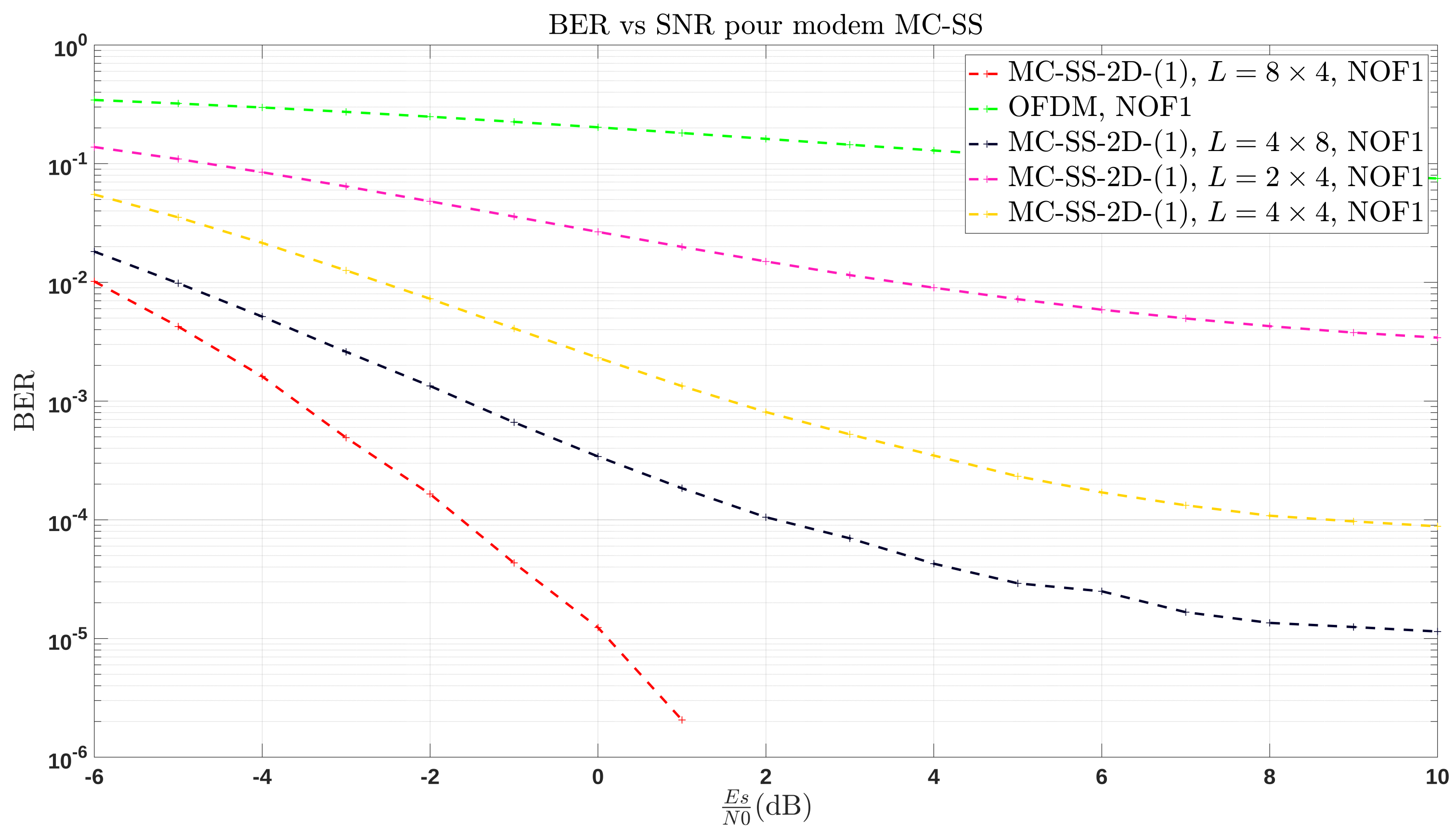
Different configurations of the modem were tested on the NOF1 channel. The modem is using 256 subcarriers and a 4 kHz passband with no channel coding and no pulse shaping filter. An OFDM symbol lasts 80 ms with a chip rate of 4 ksymb/s.
In Figure 8 and Figure 9, E s denotes the energy per chip symbol which includes both the data and pilots, N 0 is the noise power spectral density. Results reported in Figure 8 and Figure 9 were obtained by averaging the BER (bit error rate) over 300 realizations of the NOF1 channel. Each realization is a 30-s time and frequency selective channel. The signal goes five times through each 30-s channel of the 60 available. BER is calculated for each realization, and only the average over all realizations is shown. No channel coding for error detection and correction were used. Each modem has a 4 kHz bandwidth. OVSF and Gold sequences were used respectively for the spreading and scrambling process. Performances of the proposed modem is compared to an OFDM modem using 256 subcarriers and an LS estimation with half of its subcarriers being pilots.
Watermark channel can be very selective in frequency and time domain. For instance the NCS1 channel has a half coherence time of 100 ms meaning that each OFDM symbol (80 ms) needs its own pilots to properly estimate the channel frequency response. Parameters of the simulation are summarized in Table 1.
As can be observed, increasing SF makes system more resilient to noise, hence improving BER at low E s N 0 . Depending on transmission conditions, greater SF may be used. However, increasing SF reduces the throughput of the modem meaning a packet will take longer to be sent. Furthermore, in Figure 8, 2 MC-SS-2D modems have a SF of 32 but different performances. Indeed, unlike to NCS1 channel, NOF1 channel varies slowly in time reducing the impact of time diversity. Therefore, a greater SF in frequency domain brings better results. However, SF in frequency domain is limited by number of subcarriers and the passband. These results show the robustness of the designed modem. In addition, SF can easily be modified to change the processing gain and adapt to SNR and range. Such characteristics are interesting for AUVs applications. The distribution of the SS in the time and frequency domains can affect the performances of the modem and its optimization is important and challenging.

6. On the Optimization of the Time/Frequency Allocation of the Spreading Code

One of the key point of the proposed modem is to use spreading in time and frequency to improve the robustness and create a flexible design that uses time and frequency diversity. However, choosing the best time/frequency allocation can be a challenging task.
Many approaches can be used to optimize/adapt the parameters of the modem to the channel. Usually, some kind of channel knowledge is supposed at the transmitter. This knowledge is often obtained through a feedback link [21,22,23,24]. Although this approach can be efficient, it is energy costly. Furthermore, for some underwater communications applications, a feedback link can be hard to implement, expensive, and might not be feasible over long range communication [25]. In the proposed application, acoustic communication over tens of km are envisaged. For our use case, the hypothesis of some kind of channel knowledge by the use of a feedback link is not appropriated and will not be considered.
Another approach consists of simulating a channel based on information on the communications environment, such as the communication range, the relative speed between the transmitter and the receiver and the water depth. This approach was used in [26]. Currently, AUVs are used for planned missions. In that case, the needed information to simulate the channel can be easily obtained beforehand. Therefore we will assume the knowledge of the following information:
  • Communication range;
  • Depth of water;
  • Depth of transducers;
  • Relative speed between emitter and receiver.

Choosing the Allocation of the Spreading Code

Optimizing the time and frequency allocation of the spreading code means to exploit as best as possible the time and frequency diversity of the channel.
In order to achieve this result, we first must estimate the selectivity of the channel that is the time and the bandwidth coherence. The time coherence T c o h and the bandwidth coherence B c o h , respectively, depends on the Doppler spread Δ f and the delay spread Δ t of the channel.
T c o h = 1 Δ f
B c o h = 1 Δ t
As mentioned before, the diversity of the channel is exploited when two chips of the same data symbol are affected by independent coefficients of the channel. Since an interleaver is used in the frequency domain, the frequency spacing between two chips depends on the bandwidth B p used and the SF in frequency Q. It is defined as:
δ c h i p s = B p Q
For perfect exploitation of the frequency diversity, Q must be chosen so δ c h i p s > B c o h .
We have less control over the exploitation of time diversity. Unlike frequency spreading, no interleaver is used in the time domain. Therefore, to exploit the time diversity, the time gap between two chips must be greater than T c o h . In order to estimate the value of Δ f and Δ t , we use a channel simulator, such as in [26]. The overall process is presented in Figure 10.
As presented in Figure 10, the previously mentioned information on the environment are used to simulate the channel and compute a budget link of the communication. The budget link is computed using the communication range, the passband used and UAC attenuation models, such as the Thorp model [27]. With the budget link a total spreading Q × M can be determined. A channel simulator based on ray tracing method can be used to obtain a simulated Doppler spectrum and power delay profile. Using the Doppler spectrum and power delay profile, one can, respectively, estimate Δ f and Δ t . Finally, the total SF can be allocating in time and frequency to match as best as possible the coherence time and coherence bandwidth.

7. Underwater AIS Relay

7.1. Automatic Identification System

Automatic Identification System (AIS) is a tracking system based on reports provided by the ships carrying an AIS transponder. This navigation aid system is originally designed for maritime safety (collision avoidance) and communications between ship and shore, or between different ships. Even only giving indications on a portion of maritime traffic, this self-reporting system is a worldwide standard and, therefore, a coherent source of information for global traffic analysis. More precisely, this broadcasting system can receive the navigation information form other ships or vessels and meanwhile broadcasts own ship’s states at a certain time interval. This time interval varies with types of the AIS and navigation states of ships. The ships regularly exchange information, such as their positions, identity, and navigation status.
Differently than other operational coastal active systems for maritime surveillance, AIS is characterized by considerable coverage (VHF propagation) together with a relatively accurate positioning performance [28,29]. AIS standard is defined by International Association of Marine Aids to Navigation and Lighthouse Authorities (IALA) and International Telecommunication Union (ITU) [30].
According to AIS standard, ships have to send their positions at a rate according to their kinematic from one packet every 2–10 s while moving to 3 min at anchor. Ships will also send other information, such as identity or shipment’s type.
There are currently 27 different existing messages types among the 64 possibilities. A time slot is 26.67 ms long with 256 bits meaning that the raw bit rate (BR) of AIS is 9600 bps. One message can use one up to five time slots to be sent. An AIS time slot is shown in Figure 11. The size of the data field can vary depending on the number of times slots used. In Figure 11, the structure is faithful for a message using one time slot.

7.2. Description of the Application

Since GPS signals cannot be received underwater, AUVs need to surface to calibrate their navigational devices. To avoid collisions with ships during the surfacing process, AUVs need to know the position of ships. A solution to this problem is to communicate the positions of ships to AUVs. Fortunately, ships often communicate their positions and other information through the AIS. This system is used to avoid collisions between ships and survey the maritime traffic. Therefore, it makes sense to extend it to underwater vehicles, such as submarines and AUVs.
By having a surface buoy or a ship, it is possible to collect data about the surrounding ships and then forward them to the AUV fleet. Extending AIS to submarines has already been proposed as an application of JANUS protocol [31,32]. JANUS aims to enable communication between heterogeneous devices by using a common protocol and is, therefore, used to integrate the AUVs and submarines into the AIS system. Using this protocol, any ship can communicate with the AUVs. In some scenarios where we want to secure the integrity of the AUVs as much as possible, it may be preferable to separate the AUVs from the AIS system and create a private communication link between the AUVs and a trusted buoy.

7.3. Reducing the Load for Underwater Communications

An underwater acoustic channel is characterized at least by three major factors: an attenuation proportional to the signal frequency, time-varying multipath and low speed of propagation (c = 1500 m·s 1 ) inducing greater multipath and Doppler effects [6]. Due to properties of channel, its capacity is limited at large distances, the raw BR of the modem will be quite low (a few hundred bps at tens of kilometers). Therefore, it is not possible to simply relay all AIS messages to the AUVs. Messages must be compressed to obtain the target BR without loss of important information. To reduce the amount of data, one has to select the relevant information. The goal is to reduce the collisions likelihood between submarines and ships. Therefore, information, such as the type of shipment or origin of ship, are not needed. The important information are:
  • Latitude, longitude for the ship position;
  • Maritime Mobile Service Identity (MMSI) for identification purpose and, thus, differentiating the vessels;
  • Course and speed of the ship to predict its path.
All these information are all contained in five different messages types (1, 2, 3, 18, and 19) [30]. Latitude, longitude, MMSI, course over ground and speed over ground are coded, respectively, on 27 bits, 28 bits, 30 bits, 12 bits, and 10 bits. Hence, by extracting only these information, we need to send 107 bits instead of the 256 bits of the time slot. Further improvements on the load to relay can be made on some fields. As said previously, the main goal of the application is to reduce the risk of collision for AUVs. AUVs only need to know the location of surrounding ships. Hence, we can reduce the size of MMSI, latitude, and longitude fields without any accuracy lost.
The MMSI is coded on 30 bits and can, therefore, identify a lot of ships. However, during a mission, the area covered by the AUVs will be quite ’small’ compared to earth scale, a few tens of kilometers for instance. Being able to identify a lot of ships is not needed. However, MMSI also contains information, such as country of ship. It might be interesting in some applications to create classes of vessels. Still, with a 10 bits long identifier, it is possible to create 8 classes of 128 boats each which should be enough for most applications.
Since the covered area is limited, the latitude and longitude can be reduced without losing position accuracy. The most significant bits will remain the same for a given area. Therefore, they carry no information and can be removed without affecting the accuracy of the position [33]. Analysis of a lot of real AIS messages collected at shore in Brittany (France), show that only 21 bits can be used for both latitude and longitude.
Through the described methods, 182 bits of the 256 bits can be saved by message for messages types 1, 2, 3, and 18 giving a compression ratio of 3.46 . Further compression could be achieved but at the cost of localization accuracy loss. It would be interesting to study the accuracy needed for AUVs and how it impacts the surfacing time of AUVs.
Reducing the payload to relay is important to increase the number of ships the modem can handle. Even with these improvements, the BR difference between AIS and underwater communication stays important. Indeed, an underwater modified AIS packet may take more than 1 s to be transferred depending on the parameters. For example, with Q = 4 and M = 8 , the modem needs 1.28 s (2 MC-SS-2D symbols) to send 1 AIS packet. Presented watermark simulations can be used to analyze the performances of the modem in that scenario. Considering an AIS packet has 74 bits, the packet error rate (PER) can be measured. One packet will be a round number of MC-SS-2D symbols with at least 74 bits. Table 2 shows the PER at an SNR of 3dB for different configurations and with no channel coding.
This table confirms the performance results of the Figure 8 and Figure 9. Using a spreading factor SF = 32, the configuration 8 × 4 is better than 4 × 8 because it reduces the bit error rate and packet error rate for NOF1 channel. For NCS1 channel, performance is rather similar whatever the configuration. Increase the spreading factor improves the performance. OFDM is not able to provide a reliable link on these channels for the considered SNR.

8. Conclusions

In this paper, a modem designed for AUVs applications is proposed. This modem combines multi-carrier signal and 2D spreading. A variable length spreading sequence combined with OFDM creates a flexible design that uses frequency diversity, time diversity, and adds a processing gain to transmit at various distances. The modem was tested using realistic channels of the watermark benchmark. Results shows the effectiveness of SF to improve the error rate at low E s N 0 . In addition, by choosing a SF according to the coherence bandwidth and the coherence time of the channel the BER can be further improved. A method to choose the time/frequency allocation of the SF is also proposed. Robustness and adaptability of the modem is interesting for AUVs applications where the communication needs to be reliable even if the communication range varies. A possible application where the modem is used to relay AIS data to AUVs is presented. Further potential improvements for this modem, such as short length channel coding and reducing the number of pilots are being looked upon. Furthermore, using a platform like IROMI [34], the modem will be tested at sea.

Author Contributions

Conceptualization, S.I.; C.L.; A.-O.B.; J.-J.S.; methodology, S.I.; C.L.; A.-O.B.; J.-J.S.; software, S.I.; validation, S.I.; C.L.; A.-O.B.; J.-J.S.; formal analysis, S.I.; C.L.; A.-O.B.; J.-J.S.; investigation, S.I.; C.L.; A.-O.B.; J.-J.S.; writing—original draft preparation, S.I.; C.L.; A.-O.B.; J.-J.S.; writing—review and editing, S.I.; C.L.; A.-O.B.; J.-J.S.; visualization, S.I.; supervision, C.L.; A.-O.B.; J.-J.S. All authors have read and agreed to the published version of the manuscript.

Funding

This work was supported in part by Region Bretagne and THALES, in the context of the WAVES laboratory and the SAAM project.

Institutional Review Board Statement

Not applicable.

Informed Consent Statement

Not applicable.

Data Availability Statement

Not applicable.

Conflicts of Interest

The authors declare no conflict of interest.

Appendix A. Doppler Estimation

In UAC, the Doppler deeply affects the received signal. Unlike radio communications, in UAC, Doppler not only creates a shift of the carrier frequency but also a time compression/dilatation [35]. Doppler d for a constant speed v between transmitter and receiver can be approximated by:
d = 1 v c
The method described in [35,36] allows one to jointly estimate the Doppler, detect, and synchronize the signal. This method uses a pilot signal and a bank of matched filters. Each filter in this filter bank is a unique time compression/dilatation of a pilot signal. Hence, each filter is matched to a pilot signal affected by one possible Doppler shift.
Theses filters can be created by resampling the pilot signal. Let s 0 ( t ) be the OFDM pilot signal:
s 0 ( t ) = e x p ( j 2 π f 0 t ) ( n = 0 ) ( N 1 ) q 0 ( n ) e x p ( j 2 π n B t ) g ( t )
where N is the number of subcarriers, q 0 ( n ) is the nth symbol, B is the subcarrier spacing, g ( t ) is the pulse-shaping filter and f 0 is the non-centered carrier frequency. Once affected by a Doppler shift d = 1 v c , it becomes:
s 0 ( t , v ) = e x p ( j 2 π f 0 t d ) n = 0 N 1 q 0 ( n ) e x p ( j 2 π n B t d ) g ( t d )
Matched filters of s 0 ( t , v ) are created.
By correlating the filter bank with the received samples, Doppler can be estimated as equal to the compression/dilatation of the filter with the maximum correlation peak. Figure A1 shows the simulated result of the correlation between an OFDM signal affected by a Doppler shift and a bank of filters.
In Figure A1, R ( u , v ) is the result of the cross-correlation between the filters and the received signal. It depends on the delay and the relative speed v used to create the filters.
R ( u , v ) can be defined as followed:
R ( u , v ) = s 0 ( t u 0 , v 0 ) s 0 ( t u ) , v   d t
where u 0 and v 0 are the delay and Doppler speed affecting the sent pilot signal s 0 ( t ) .
In Figure A1, a high correlation peak between the received signal and the filter simulating a 3 m·s 1 Doppler shift is present. Two lobes can be seen. They are the result of the cyclic prefix correlation. The estimated Doppler shift is the one used to create the filter giving the highest correlation peak.
Figure A1. Bank filter simulation result R ( u , v ) (Passband 16–20 kHz, v 0 = 3 m/s, u 0 = 0.1 s), AWGN channel.
Applsci 12 04166 g0a1
Once estimated, Doppler is compensated by resampling the signal. This maximum correlation peak can be used for synchronization but also for detection by comparing it to a threshold defined by CA-CFAR (Cell Averaging Constant False Alarm Rate) method [37]. The pilot signal is generated in a similar way as the data signal and is, therefore, a MC-SS symbol with M = 1 . To increase its difference with the data signal, a distinctive scrambling sequence is used for the pilot signal. The frame structure is a pilot signal followed by MC-SS symbols. Using this method, the range of Doppler speeds that can be estimated depends on the filters used and the Doppler speed they simulate. The modem proposed here can estimate a Doppler speed v up to ± 10 m·s 1 .

References

  1. Wynn, R.B.; Huvenne, V.A.I.; Le Bas, T.P.; Murton, B.J.; Connelly, D.P.; Bett, B.J.; Ruhl, H.A.; Morris, K.J.; Peakall, J.; Parsons, D.R.; et al. Autonomous Underwater Vehicles (AUVs): Their past, present and future contributions to the advancement of marine geoscience. Mar. Geol. 2014, 352, 451–468. [Google Scholar] [CrossRef] [Green Version]
  2. Ferreira, F.; Petroccia, R.; Alves, J. Increasing the operational safety of autonomous underwater vehicles using the JANUS communication standard. In Proceedings of the 2018 IEEE/OES Autonomous Underwater Vehicle Workshop (AUV), Porto, Portugal, 6–9 November 2018; pp. 1–36. [Google Scholar]
  3. Potter, P.; Alves, J.; Green, D.; Zappa, G.; Nissen, I.; McCoy, K. The JANUS Underwater Communications Standard. In Proceedings of the 2014 Underwater Communications and Networking (UComms), Sestri Levante, Italy, 3–5 September 2014; pp. 1–4. [Google Scholar]
  4. Walree, P.; Sangfelt, E.; Leus, G. Multicarrier spread spectrum for Covert Acoustic Communications. In Proceedings of the OCEANS 2008, Quebec City, QC, Canada, 15–18 September 2008. [Google Scholar]
  5. Martins, R. Disruption/delay tolerant networking with low-bandwidth underwater acoustic modems. In Proceedings of the 2010 IEEE/OES Autonomous Underwater Vehicles, Monterey, CA, USA, 1–3 September 2010; pp. 1–5. [Google Scholar]
  6. Stojanovic, M.; Preisig, J. Underwater acoustic communication channels: Propagation models and statistical characterization. IEEE Commun. Mag. 2009, 47, 84–89. [Google Scholar] [CrossRef]
  7. Kilfoyle, D.; Baggeroer, A. The State of the Art in Underwater Acoustic Telemetry. IEEE J. Ocean. Eng. 2000, 25, 4–27. [Google Scholar] [CrossRef]
  8. Campagnaro, F.; Signori, A.; Zorzi, M. Wireless Remote Control for Underwater Vehicles. Appl. Sci. 2020, 8, 736. [Google Scholar] [CrossRef]
  9. Zia, M.Y.I.; Poncela, J.; Otero, P. State-of-the-Art Underwater Acoustic Communication Modems: Classifications, Analyses and Design Challenges. Wirel. Pers. Commun. 2021, 116, 1325–1360. [Google Scholar] [CrossRef]
  10. Scholtz, R.A. The origins of spread-spectrum communication. IEEE Trans. Commun. 1982, 30, 822–854. [Google Scholar] [CrossRef]
  11. Schilling, D.L.; Milstein, L.B.; Pickholtz, R.L.; Kullback, M.; Miller, F. Spread spectrum for commercial communications. IEEE Commun. Mag. 1991, 29, 66–79. [Google Scholar] [CrossRef]
  12. Fazel, K.; Kaiser, S. Multi-Carrier and Spread Spectrum Systems: From OFDM and MCCDMA to LTE and WiMAX; Wiley: Hoboken, NJ, USA, 2008. [Google Scholar]
  13. Pallavi, P.; Dutta, P. Muti-Carrier CDMA overview with BPSK modulation in Rayleigh channel. In Proceedings of the 2010 3rd International Conference on Computer Science and Information Technology, Chengdu, China, 9–11 July 2010; pp. 464–469. [Google Scholar]
  14. Iraji, S.; Sipila, T.; Lilleberg, J. Channel estimation and signal detection for MC-CDMA in multipath fading channels. In Proceedings of the 14th IEEE Proceedings on Personal, Indoor and Mobile Radio Communications, Beijing, China, 7–10 September; 2003; pp. 2286–2290. [Google Scholar]
  15. Hara, S.; Prasad, R. Overview of multicarrier CDMA. IEEE Commun. Mag 1997, 25, 126–133. [Google Scholar] [CrossRef]
  16. Konstantakos, D.P.; Adams, A.E.; Sharif, B.S. Multicarrier code division multiple access (MC-CDMA) technique for underwater acoustic communication networks using short spreading sequences. IEE Proc.-Radar Sonar Navig. 2004, 151, 231–239. [Google Scholar] [CrossRef]
  17. Yang, C.M.; Lin, P.H.; Yang, G.C.; Kwong, W.C. 2D orthogonal spreading codes for multicarrier DS-CDMA systems. IEEE Int. Conf. Commun. 2003, 25, 3277–3281. [Google Scholar]
  18. Hsieh, M.-H.; Wei, C.-H. Channel estimation for OFDM systems based on comb-type pilot arrangement in frequency selective fading channels. IEEE Trans. Consum. Electron. 1998, 44, 217–225. [Google Scholar] [CrossRef] [Green Version]
  19. Proakis, J.; Salehi, M. Digital Communications; McGraw-Hill: Boston, MA, USA, 2007. [Google Scholar]
  20. Van Walree, P.A.; Socheleau, F.X.; Otnes, R.; Jenserud, T. The Watermark Benchmark for Underwater Acoustic Modulation Schemes. IEEE J. Ocean. Eng. 2017, 42, 1007–1018. [Google Scholar] [CrossRef] [Green Version]
  21. Radosevic, A.; Ahmed, R.; Duman, T.M.; Proakis, J.G.; Stojanovic, M. Adaptive OFDM Modulation for Underwater Acoustic Communications: Design Considerations and Experimental Results. IEEE J. Ocean. Eng. 2014, 39, 357–370. [Google Scholar] [CrossRef]
  22. Pottier, A.; Socheleau, F.; Laot, C. Robust Noncooperative Spectrum Sharing Game in Underwater Acoustic Interference Channels. IEEE J. Ocean. Eng. 2017, 42, 1019–1034. [Google Scholar] [CrossRef] [Green Version]
  23. Fu, Q.; Song, A. Adaptive Modulation for Underwater Acoustic Communications Based on Reinforcement Learning. In Proceedings of the OCEANS 2018 MTS/IEEE Charleston, Charleston, SC, USA, 22–25 October 2018. [Google Scholar]
  24. Wan, L.; Zhou, H.; Xu, X.; Huang, Y.; Zhou, S.; Shi, Z.; Cui, J.H. Adaptive Modulation and Coding for Underwater Acoustic OFDM. IEEE J. Ocean. Eng. 2015, 40, 327–336. [Google Scholar] [CrossRef]
  25. Huang, J.; Diamant, R. Adaptive Modulation for Long-Range Underwater Acoustic Communication. IEEE Trans. Wirel. Commun. 2020, 19, 6844–6857. [Google Scholar] [CrossRef]
  26. Gussen, C.M.; Laot, C.; Socheleau, F.X.; Zerr, B.; Le Mézo, T.; Bourdon, R.; Le Berre, C. Optimization of Acoustic Communication Links for a Swarm of AUVs. Appl. Sci. 2021, 11, 8200. [Google Scholar] [CrossRef]
  27. Brekhovskikh, L.; Lysanov, Y. Fundamentals of Ocean Acoustics; Springer: Berlin, Germany, 1991. [Google Scholar]
  28. Angrisano, A.; Gaglione, S.; Gioia, C. Performance assessment of aided global navigation satellite systems for land navigation. IET Radar Sonar Navig. 2010, 7, 671–680. [Google Scholar] [CrossRef]
  29. Mazzarela, F.; Vespe, M.; Alessandrini, A.; Tarchi, D.; Aulicinio, G.; Vollero, A. A novel anomaly detection approach to identify intentional AIS on-off switching. Expert Syst. Appl. 2017, 78, 110–123. [Google Scholar] [CrossRef]
  30. ITU. Technical Characteristics for an Automatic Identification System Using Time Division Multiple Access in the VHF Maritime Mobile Frequency Band; Recommendation ITU: Geneva, Switzerland, 2014. [Google Scholar]
  31. Petroccia, R.; Alves, J.; Zappa, G. JANUS-Based Services for Operationally Relevant Underwater Applications. IEEE J. Ocean. Eng. 2017, 42, 994–1006. [Google Scholar] [CrossRef]
  32. Ferreira, F.; Petroccia, R.; Alves, J. Underwater/surface collision avoidance using underwater acoustic communications—A preliminary analysis. In Proceedings of the OCEANS, Marseille, France, 17–20 June 2019; pp. 1–4. [Google Scholar]
  33. Seat, T. A data compression method by dropping Most Significant Bits and its application to transmission of position data. In Proceedings of the 2016 Techno-Ocean, Kobe, Japan, 6–8 October 2016; pp. 181–184. [Google Scholar]
  34. Laboratoire Marin d’Acoustique et d’Imagerie de la Rade: L-Mair. Available online: https://isen-nantes.fr/recherche-4/laboratoire-marin-dacoustique-et-dimagerie-de-la-rade-l-mair/ (accessed on 10 March 2022).
  35. Imbert, S.; Ansel, G.; Laot, C. Frame Detection and Synchronization for a SIMO Receiver in presence of Doppler Shift for Underwater Acoustic Communications. In Proceedings of the OCEANS, Marseille, France, 17–20 June 2019; pp. 1–4. [Google Scholar]
  36. Sharif, B.S.; Neasham, J.; Hinton, O.R.; Adams, A.E. A computationally efficient Doppler compensation system for underwater acoustic communications. IEEE J. Ocean. Eng. 2000, 25, 52–61. [Google Scholar] [CrossRef]
  37. Rohling, H. Radar CFAR Thresholding in Clutter and Multiple Target Situations. IEEE Trans. AES 1983, 19, 608–621. [Google Scholar] [CrossRef]
Figure 1. Performance of academic and commercial modems.
Applsci 12 04166 g001
Figure 2. MC-SS 2D transmitter structure.
Applsci 12 04166 g002
Figure 3. Example: QPSK symbols repetition for MC-SS-2D.
Applsci 12 04166 g003
Figure 4. Example: spreading in MC-SS-2D.
Applsci 12 04166 g004
Figure 5. Example: frequency interleaving in MC-SS-2D.
Applsci 12 04166 g005
Figure 6. MC-SS 2D receiver structure.
Applsci 12 04166 g006
Figure 7. Simulation results over an 8-path Rayleigh block fading channel with a SF of L = 8 .
Applsci 12 04166 g007
Figure 8. BER vs. E s N 0 for a communication on NOF1 channel (frequency passband: 10.5 kHz– 14.5 kHz).
Applsci 12 04166 g008
Figure 9. BER vs. E s N 0 for a communication on NCS1 (Norway Continental Shelf) channel [20] (frequency passband: 10.5 kHz– 14.5 kHz).
Applsci 12 04166 g009
Figure 10. General process for allocating the spreading sequence in the time and frequency domain.
Applsci 12 04166 g010
Figure 11. AIS data packet structure.
Applsci 12 04166 g011
Table 1. Signals description.
Q × M Bits in 1 MC-SS-2DUser Bit Rate
MC-SS-2D 2 × 4 128400 bps
MC-SS-2D 4 × 4 64200 bps
MC-SS-2D 4 × 8 64100 bps
OFDM12563200 bps
Table 2. Packet error rate at an SNR of 3 dB.
Q × M 4 × 4 4 × 8 8 × 4 8 × 8 OFDM
NOF1 channel:0.0580.0060.000301
NCS1 channel:0.7530.3020.2370.0311
Publisher’s Note: MDPI stays neutral with regard to jurisdictional claims in published maps and institutional affiliations.

