1. Introduction
Linear accelerator based free-electron lasers [
1,
2,
3,
4,
5] produce extremely short, brilliant and coherent X-ray pulses [
6,
7] and have become an enabling technology for interdisciplinary experiments worldwide. Advancing the frontier of resolving the structure of matters with X-rays demands modern user facilities to provide photon beams at a wavelength of 1 Å and below, the so-called sub-ångström regime of hard X-rays. Successful operation of the European X-ray Free-Electron Laser [
1,
8] has been delivering soft and hard X-ray pulses for routine user experiments since 2017. At a typical electron beam energy of 14 GeV, stable, high-intensity self-amplified spontaneous emission (SASE [
6]) performance is achieved for 0.6–14 keV in routine user runs [
9,
10,
11], while in test runs, good lasing signals towards 25 keV were achieved with only limited tuning time.
The accessible photon wavelength
via SASE depends on electron beam energy
, undulator parameter K and undulator period
[
6]. Due to the inverse scaling of
with the square of
, SASE operation in the sub-ångström regime apparently benefits significantly from boosting the particle energy. The undulator K is proportional to the product of
and B [
12], where B stands for the undulator field. For a given undulator period, a larger undulator gap results in a weaker magnetic field characterized by a smaller K value, leading to a shorter photon wavelength. Practically, a reachable undulator K value depends on the control capability (range and accuracy) of the undulator gap. Reducing the undulator period certainly shifts the emission regime towards shorter photon wavelengths. The choice of short-period undulators can be either in-vacuum undulators or superconducting undulators [
13]. The latter option offers a combination of a short period and a strong magnetic field. Furthermore, superconducting undulators enable period doubling [
14], that is, dynamic change of the undulator period, which enhances the tunability and range of accessible photon energies. The standard undulators with longer periods standing out-of-vacuum can still be utilized along with advanced lasing concepts such as harmonic lasing [
15,
16] and reverse tapering of the main undulator plus an afterburner for background-free harmonics generation [
17,
18].
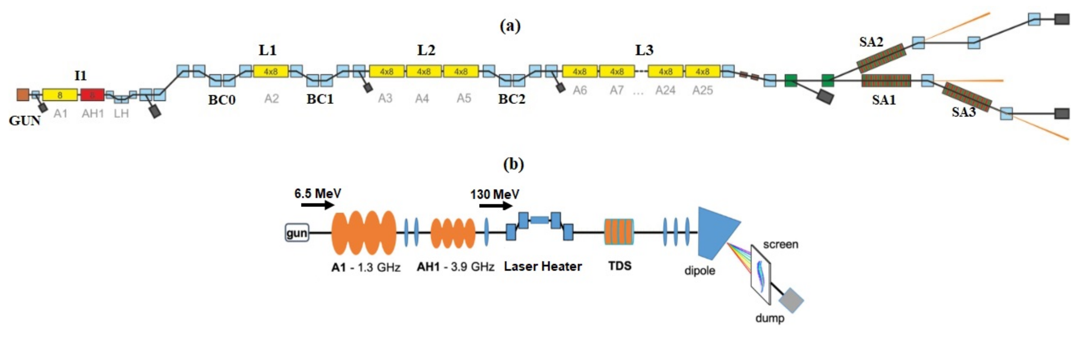
The interests in operating the European XFEL in the sub-ångström regime have been initially expressed by our on-site users. This includes, for example, the X-ray microscopy at a MHz rate of various dynamic samples, the MHz X-ray stereography or triscopy via diamond splitters, and so on. Specific properties of the required radiation can be defined by the users once the machine capability is first demonstrated in terms of the SASE wavelength and intensity. At the European XFEL, the superconducting linac can accelerate the electron beam up to 17.5 GeV. The baseline hard X-ray variable-gap undulators have a period of 4 cm. The total undulator length is about 175 m for SA1 undulators [see
Figure 1a]. Such a configuration allows the production of photon beams with high energy at 25 keV and above.
However, the FEL performance depends on the achievable qualities of electron beams in the undulators. The transverse coherence depends on the ratio of geometric emittance to photon wavelength [
19]. The FEL gain length increases with the increase of the transverse emittance and uncorrelated energy spread of the electron bunch, and decreases with an increase in peak current [
12]. The obtained gain length should be sufficiently small, such that the SASE process at a resonant wavelength can grow within a given undulator length until saturation. Typically, an undulator length of about 20 times the obtained gain length allows to stably deliver high-power photon beams to the users at a suitable wavelength.
In this article, transverse emittance budgets of the electron bunches are first optimized in the photo-injector via transverse laser pulse shaping at a series of accelerating gradients at the cathode in the simulations. The obtained bunches are transported through the present XFEL beamline [
20] via start-to-end simulations with collective effects. This also includes compression of the electron bunches in the multi-stage compression system [
21] to a few kiloamperes’ peak current by the front of the undulator beamline. Using the optimized electron bunches, SASE performance in the sub-ångström working regime of the facility, here covering a photon energy range from 9.3 to 45 keV is explored based on existing undulators at the European XFEL. This considers a typical electron energy of 14 GeV as in routine user runs as well as a full beam energy of 17.5 GeV which was demonstrated in previous operation. It should be noted that, while some of the advanced lasing concepts mentioned above have been under development and/or are being planned at the European XFEL, they are not considered in this study.
Additionally, in light of global developments towards continuous-wave (CW) operation [
22,
23,
24,
25,
26,
27,
28,
29] of FEL facilities at LCLS-II, SHINE, MariX, and so forth, a potential dual-mode operation of the European XFEL is under consideration. This refers to a present pulsed operation mode with a duty cycle of about 1%, that is, a burst of up to 2700 bunches within a 0.6 ms-long 10 Hz-repetition bunch train, and a CW mode at 100% duty cycle. Compared to the pulsed mode, both the cathode accelerating gradient and the total beam energy are reduced in the CW mode [
30,
31,
32]. Therefore, the SASE performance of a potential CW mode, operating at reduced cathode gradients of 40 MV/m and 50 MV/m and a reduced final beam energy of about 7 GeV, is studied in parallel to the pulsed mode of the present machine. This aims to justify the electron bunch qualities under distinct working-mode scenarios. It should also be pointed out that only the existing undulators at the European XFEL with a period of 4 cm are taken into account for computations. Detailed design studies of a complementary CW mode with requirements and considerations of modifying the present facility will be reported in [
33].
The paper is organized as follows: In
Section 2, the transverse shape of the cathode drive laser pulse is optimized based on particle tracking simulations, where three-dimensional space-charge fields are computed iteratively. An optimum transverse distribution with a truncated-Gaussian profile is selected for linearizing space-charge fields in close vicinity of the cathode, while keeping the longitudinal characteristics (length and shape) of the cathode drive laser pulse the same as the ones which are currently used at the facility. Utilizing such an optimal transverse shape of the cathode laser pulse, detailed transverse emittance budgets are evaluated in
Section 3 by optimizing the projected transverse emittance in the photoinjector at different accelerating field gradients of 40 MV/m, 50 MV/m and 56 MV/m at the cathode, taking into account multiple injector parameters. In
Section 4, start-to-end beam dynamics simulations are carried out all the way through the linac to the undulator entrance. Collective effects such as 3D space-charge, wake fields and CSR effects are included. The bunches are compressed to a few kiloamperes’ peak currents and the final bunch qualities are presented. Finally, the SASE performance of the optimized bunches in the sub-ångström regime are systematically investigated in
Section 5. This is performed for two operation modes, the pulsed mode at 14 GeV and 17.5 GeV mainly at high photon energies above 20 keV, as well as a potential CW mode at accessible photon energies limited by the existing undulators at a reduced beam energy of about 7 GeV. A conclusion and an outlook are then given in
Section 6.
2. Near-Cathode Particle Dynamics
Figure 1 sketches a layout of the European XFEL and its injector section. A cesium-telluride photocathode based high-gradient L-band RF gun is in use as the electron source [
34], providing about 6.5 MeV/m beam momentum at the gun exit. The photoemission process in the gun is driven by a Nd:YVO4 laser at 266 nm [
35]. A temporal Gaussian ultraviolet (UV) pulse with an rms length of 3 ps is currently employed. Transversely, the size of the laser beam shaping aperture (BSA), which is imaged onto the photocathode, can be varied. The existing infrastructure of the laser beam line allows an adjustment of the laser beam size at the BSA position with moderate additional technical efforts. By attenuation of the pulse energy, the laser system can extract different bunch charges from the cathode [
36]. Along with the aforementioned variability in the imaging system of the laser, the emittance growth at a fixed charge can be minimized by optimization of transverse laser pulse shape via modeling of the photoemission process [
37,
38]. In addition, a typical surface roughness of the cesium-telluride photocathode produced using the present recipe is about 10 nm. Potential impacts of the cathode surface roughness on the emittance growth are not considered in this study. Interested readers can be referred to [
39,
40] for model-dependent evaluation of the emittance growth.
Here, we follow the strategy of transverse laser pulse shaping described in [
41,
42] to linearize the space-charge fields during emission from the cathode in particle tracking simulations. This is done using a programmed adapter that is incorporated with the Particle-in-Cell (PIC) object of CST Particle Studio [
43]. Three-dimensional (3D) particle tracking simulations are performed iteratively, by adapting the transverse profile of the bunched particles at the cathode, such that, for a certain transverse shape of the drive laser, the space-charge fields are linearized at the observation positions in the close-to cathode regime. This approach allows self-consistent calculation of the evolution of 3D electromagnetic fields and the associated particle dynamics at discrete time samples, also taking into account image-charge effects.
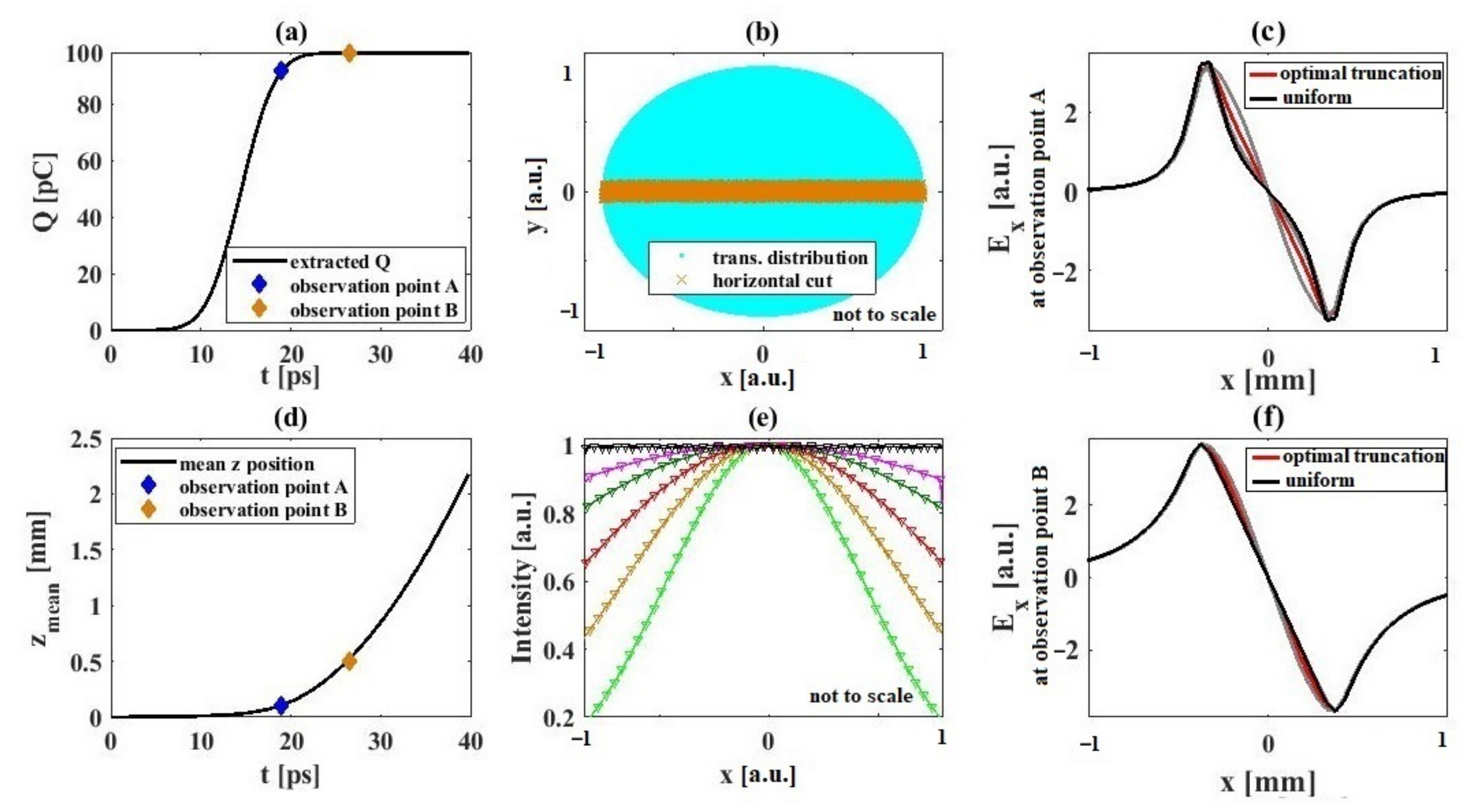
Figure 2 presents detailed results obtained from the transverse profile optimization of the cathode drive laser. Two longitudinal observation positions A and B are chosen for field computations, as marked in (a) and (d) in the evolution of the total extracted charge during emission and the mean bunch position, respectively. At these two positions, the transverse space-charge fields are computed as shown in (c) at position A during the emission, and in (f) at position B after the emission. The adaption of the transverse cathode laser distribution is quantified by adjusting the edge-to-center intensity ratio, that is, the truncation ratio of the distribution. The calculations are performed for a series of truncation ratios as illustrated in
Figure 2b, where an exemplary intensity distribution and a horizontal cut through it are shown. The corresponding, normalized projections of the intensity in this cut are depicted in
Figure 2d for different truncation ratios.
Figure 2c shows that the transverse space-charge field during the emission is most linear for a truncation ratio of about 0.65 (red curve) in comparison to a uniform distribution with a truncation ratio of 1 (black curve). The shadows represent some traces of the simulated results as corresponding to different truncation ratios. After emission, there is no pronounced difference in the field linearity as shown in
Figure 2f.
Furthermore,
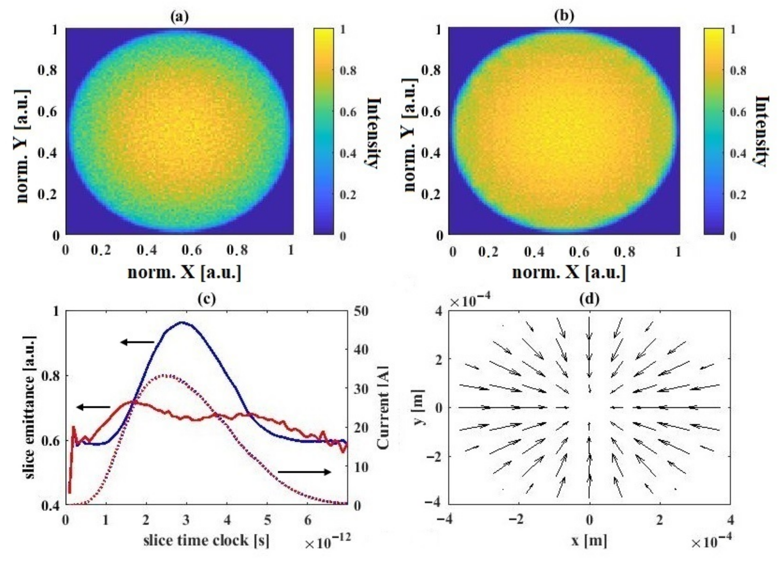
Figure 3 provides a transient view of the optimization with more insights into the characteristics of the produced particle distribution at the end of the emission process.
Figure 3a shows the transverse particle distribution when an optimal truncated-Gaussian shape of the drive laser is used. This is in comparison to the one shown in
Figure 3b where a flattop transverse laser pulse (truncation ratio of 1) is applied instead.
Figure 3c captures a transient comparison of the transverse sliced emittance along the bunch between the transverse flattop case (blue curve) and the truncated-Gaussian case (red curve) at the end of the emission process. The comparison shows a tendency of lower emittance (left axis) around the current peak (right axis) for the truncated-Gaussian case, although the absolute emittance value at this moment apparently cannot yet represent the bunch qualities. Moreover,
Figure 3d shows a vector plot of relative displacements (lengths of the vectors) on the transverse plane from the macro-particles in the flattop case (arrow tails) to those in the truncated-Gaussian case (arrow heads). Note that each pair of the macro-particles used in the vectors are born at the same time at the cathode position and are further tracked through the emission process, and that the diameter of the transverse particle distributions is the same at the cathode. This indicated that the development of the beam self-fields by utilizing a transversely optimized truncated-Gaussian distribution at the cathode plane can allow a higher charge density towards the center of the bunch at the end of the photoemission, when it is compared to the case with a flat transverse distribution. Based on the optimization approach, as shown in
Figure 2, a transverse truncated-Gaussian laser distribution with an edge-to-center intensity ratio of about 0.65 is chosen and employed for beam dynamics simulations in
Section 3.
3. Budgeting Emittance at Multiple Accelerating Gradients at the Cathode
In this section, the performance of the EuXFEL injector [
34,
38] [as shown in
Figure 1b] with the currently existing cathode laser pulse shaping capabilities, intrinsic emittance of the cathode, and position of the beamline components is studied for varying peak accelerating gradients at the cathode position. The gun solenoid strength, operation phase of the gun and rms size of the cathode laser spot are considered for the optimization. An optimal transverse shape of the cathode drive laser is applied according to the findings as presented in
Section 2. The rms length of the longitudinal Gaussian laser pulse is kept at 3 ps, which is the same as that currently used in routine operation.
The electron bunch is generated at the photocathode positioned at 0 m, then accelerated to about 6.5 MeV/c after the gun and boosted to 130 MeV/c downstream cathode at about 22 m, at which position the transverse projected emittance is calculated. The intrinsic energy of the emitted electrons is set to a nominal value of 0.55 eV [
44] for cesium-telluride cathodes. A series of numerical simulations are carried out in ASTRA [
45], driven by a simple script written in Matlab. The simulations were carried out on the MAXWELL cluster at DESY. Up to 2 million macro-particles are used for simulating 100 pC electron bunches. Interested readers are also referred to Refs. [
46,
47,
48] for detailed descriptions about the concept of emittance growth sources and compensation schemes in photocathode RF injectors.
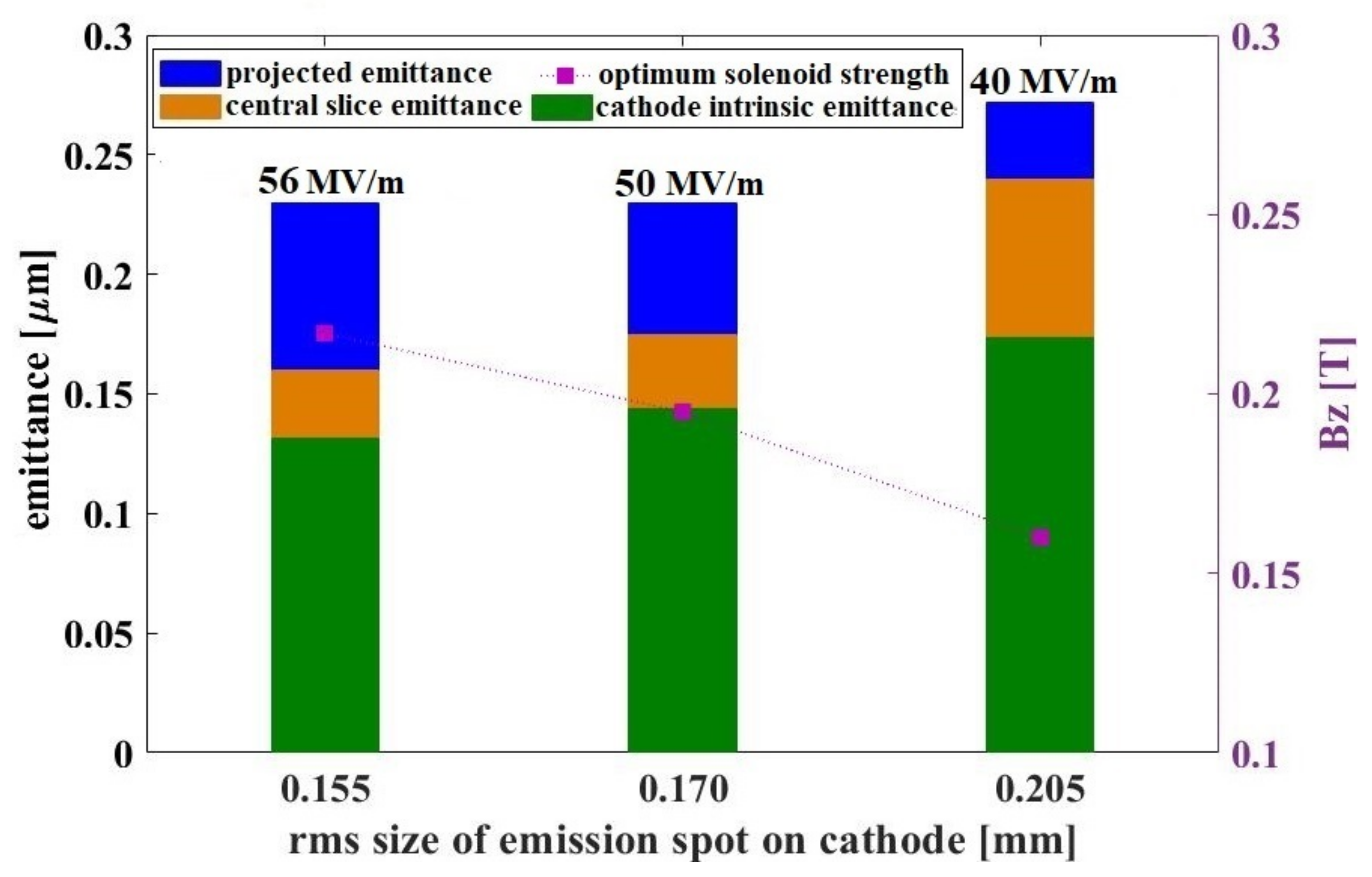
Figure 4 shows the optimized overall transverse projected emittance for 100 pC electron bunches at the injector exit using peak accelerating gradients of 56 MV/m, 50 MV/m and 40 MV/m at the cathode. The 56 MV/m case is close to an optimal state of the present operation with the pulsed injector at the European XFEL. The lower gradients, 50 MV/m and 40 MV/m, would have relevance to the case with a CW injector, in which the peak accelerating gradient is reduced to 40 MV/m with a potential improvement to 50 MV/m in superconducting RF guns [
49,
50]. The beam energy at the gun exit is reduced from about 5.96 MeV in the 56 MV/m case to 5.28 MeV and 4.21 MeV for the 50 MV/m and 40 MV/m cases, respectively. The optimal solenoid field strengths for each optimized case are shown on the right axis of
Figure 4. It can be seen, that at a reduced cathode gradient of 50 MV/m, the optimal transverse projected emittance (blue bars) is still comparable to the 56 MV/m case. The comparable emittance is achieved by increasing the laser spot size to relax the volumetric space-charge density. While this comes at the cost of higher intrinsic emittance (
Figure 4, green bars), the stronger space-charge effects at lower cathode fields are mitigated to a similar extent. However, the central slice emittance (orange bars) at 50 MV/m is increased, implying the slice formation of the bunch is still affected at a lower cathode gradient and could not be fully compensated. By further decreasing the cathode gradient to 40 MV/m, one can see that both the transverse projected emittance and the central slice emittance are degraded. It should be noted that an increase of the cathode laser pulse length may be able to compensate for the overall emittance growth at 40 MV/m. However, since this study aims to evaluate the injector performance under the conditions more close to practical operation of the facility, further lengthening and/or shaping of the temporal cathode drive laser distribution is not considered. As a reference, in previous facility operation at 100 pC, the projected transverse emittance is typically about 0.33 μm at a nominal gun gradient of about 56 MV/m, which is measured by the quadrupole scan method. This is about 30% higher than the optimized emittance one can achieve in the simulations as presented in this paper. One discrepancy source may attribute to the fact that the transverse pulse shape of the cathode drive laser is not yet experimentally optimized. Yet another source can be related to the non-uniformity of the photocathode quantum-efficiency map due to an aging effect.
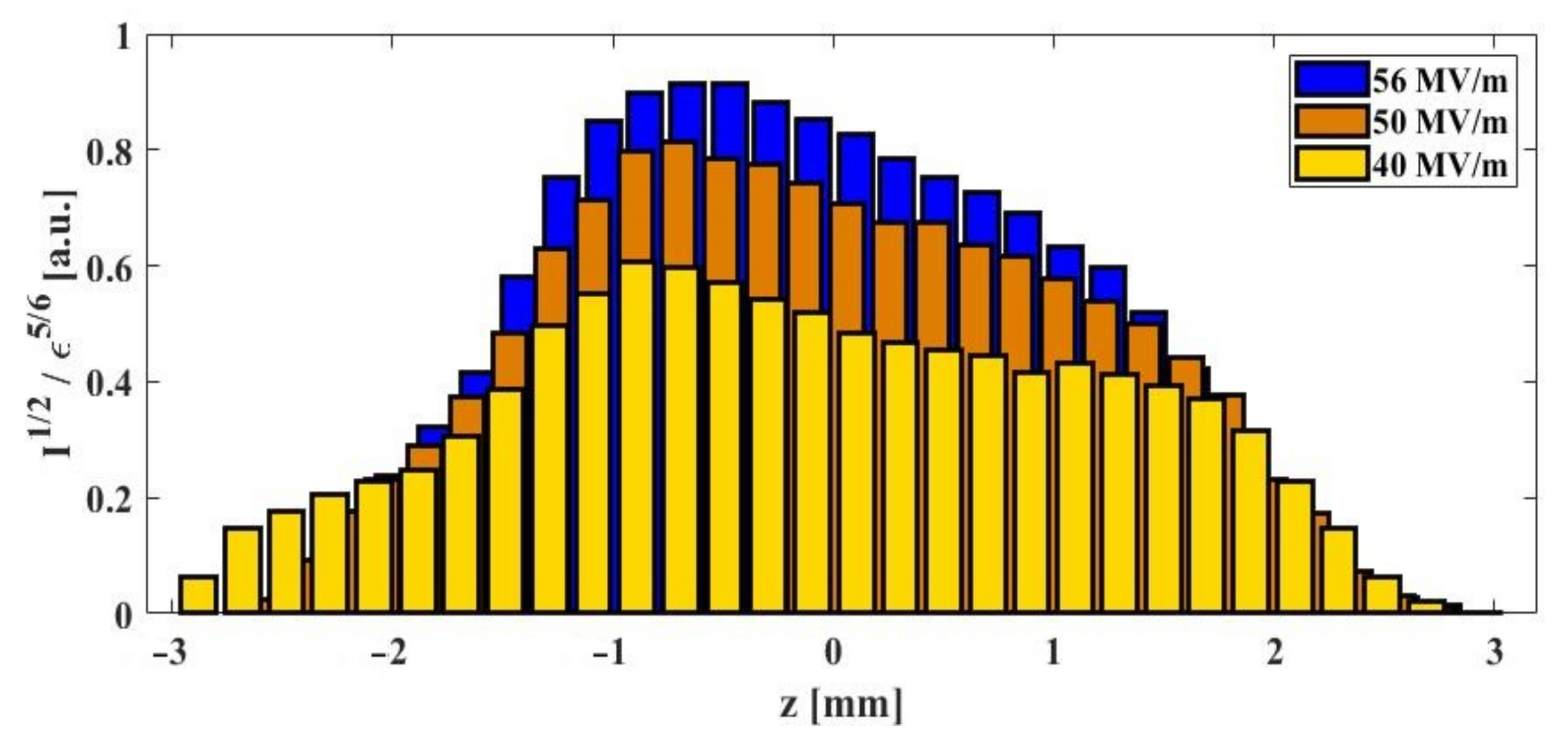
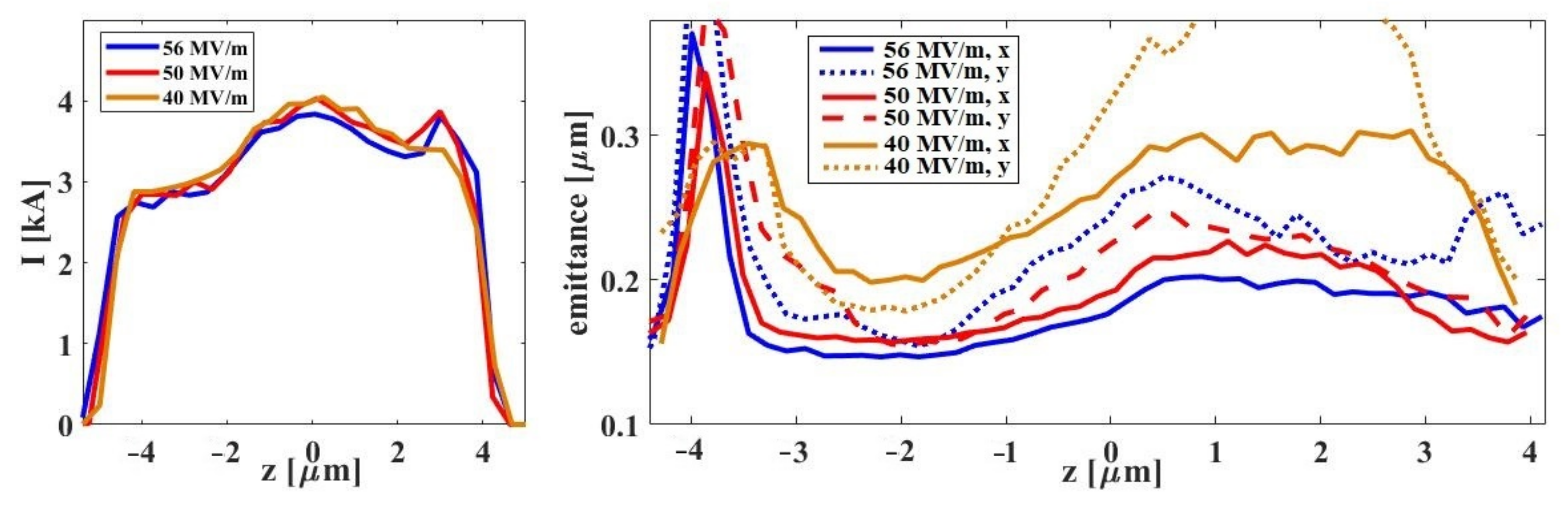
Figure 5 shows the slice emittance along the bunches at the three peak accelerating gradients under consideration. A central slice emittance growth around the current peaks with respect to the 56 MV/m case is about 6% at 50 MV/m and 30% at 40 MV/m. The peak currents are about 9.0 A, 8.5 A and 7.8 A by the end of the injector for 56 MV/m, 50 MV/m and 40 MV/m, respectively. Furthermore, an FEL gain parameter is defined according to [
12] to evaluate potential SASE performance of individual slices along the bunches, in terms of bunch quality parameters, that is,
=
/
, where
stands for the current and
represents the slice emittance.
Figure 6 illustrates the defined normalized gain parameter along the three optimized bunches. A higher gain parameter indicates higher peak current over smaller slice emittance of the bunch segments. As compared to
Figure 5, the peaks in the gain parameter are shifted away from the current peaks towards the slices with lower emittance implying a dominating role of the emittance of the produced bunches. The gain parameter of the central slices reduces with decreasing the cathode gradient. However, in this case, the uniformity of the gain parameter turns out to be better in the case of lower gradients.
4. Start-to-End Beam Physics
Using the optimized electron bunches at multiple cathode accelerating gradients in the injector, start-to-end beam physics studies of the accelerators are performed. As shown in
Figure 1a, the bunches are tracked from the injector (I1) all the way through the linac (L1/L2/L3) up to the entrance of the undulators (SA1). The particle tracking is done in the open-source code OCELOT [
51] using the charged particle beam dynamics (CPBD) module. A full machine lattice setup of the European XFEL is available online [
20]. Design optics are used. The beam matching follows a so-called artificial matching approach developed in OCELOT and the optics are not explicitly optimized for individual simulation cases in this paper. Collective effects such as 3D space-charge, 3D wakes and 1D CSR are taken into account, as described in [
52]. In this study, an energy profile along the accelerator beamline is fixed as 130 MeV, 700 MeV and 2400 MeV at three bunch compression stages, which is the same as in the present XFEL. For simplicity, a possible modification in this energy profile for the future CW mode is not considered in these simulations. The final beam energy scaling is done by adjusting the energy gain of the main linac, which results in 14 GeV and 17.5 GeV for the pulsed mode and 7.3 GeV for the CW mode. Under these conditions, the electron beam qualities in front of the undulators are investigated.
Specifically, a primary goal of start-to-end simulations is to find a suitable working point, allowing bunch compression to the target peak current while maintaining as well as possible the bunch qualities obtained from the injectors. Essentially the working point refers to a set of longitudinal beam dynamics parameters such as the R56s and beam energies at the bunch compressors, and also a set of RF parameters, including amplitudes and phases of the acceleration modules, namely A1, AH1, L1 and L2 as shown in
Figure 1a. In the following, we employ a parameter set of −44 mm, −50 mm and −30 mm as the R56s at the bunch compressors BC0, BC1 and BC2 as shown in
Figure 1a, respectively. The mapping between the RF parameters and the longitudinal beam dynamics parameters is described in [
52]. It can be noted that dedicated high-resolution simulations are performed in IMPACTZ [
53] with a real number of electrons to numerically resolve the micro-bunching effect by the so-called brute-force technique. This allows a determination of the ratio between the peak current and the energy spread at the end of the accelerator beam line with respect to an optimal laser heater working point [
54,
55]. The optimized ratio is then set as a goal for further optimization of the RF parameters as well as the mapping between the RF parameters and the longitudinal beam dynamics parameters in OCELOT [
51]. More details about this approach will be published elsewhere, for example, in [
33].
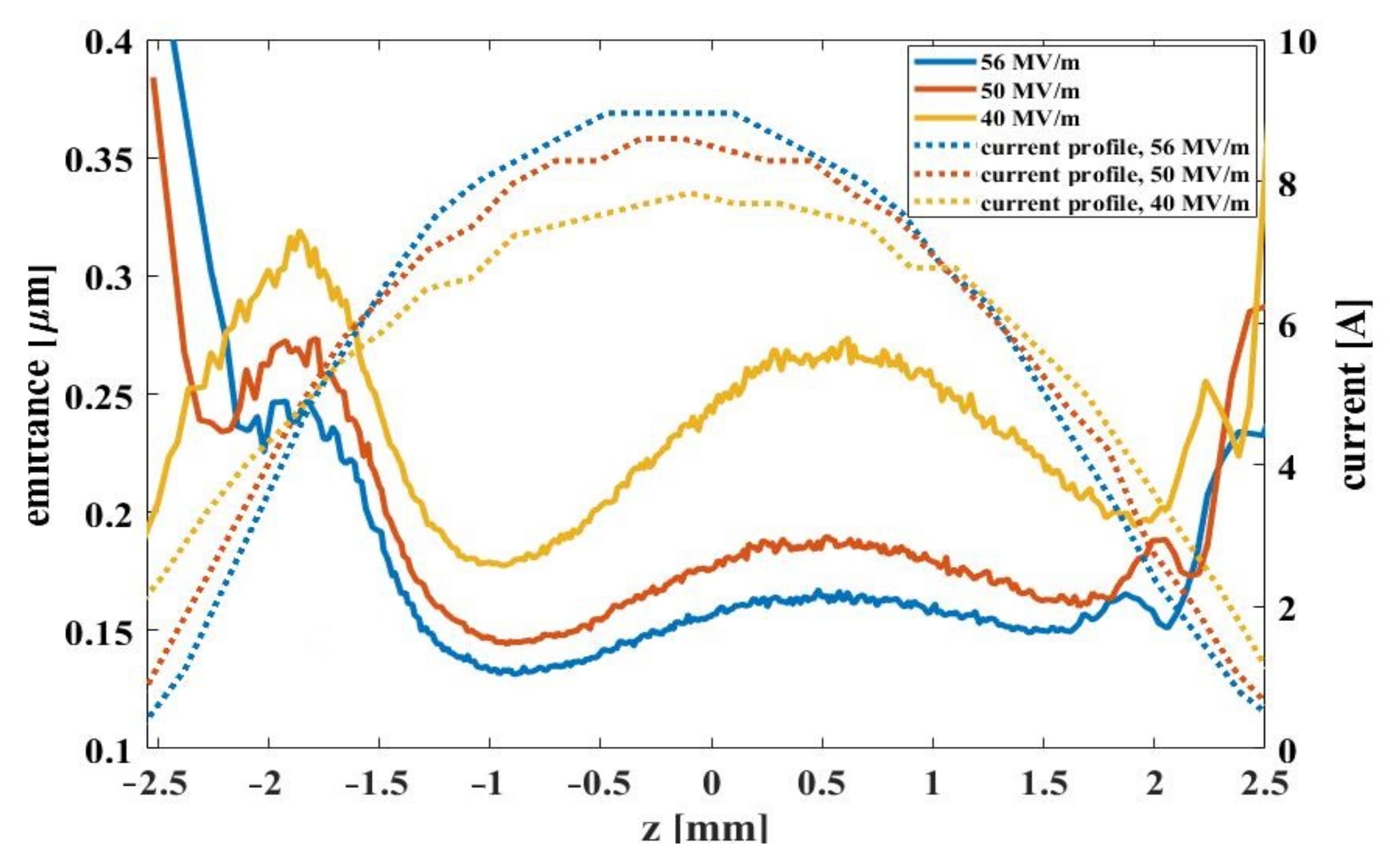
Figure 7 shows the current profiles (left) and the slice emittance (right) along the three optimized electron bunches in front of the SA1 undulators [see
Figure 1a]. As shown, the working points are found for all three cases, such that the peak currents close to 4 kA can be reached after the compression with a peak energy spread of about 2 MeV. The final slice emittance are obtained tracking the bunches generated with different accelerating gradients at the cathode through the whole accelerator beam line. The 56 MV/m case shows the lowest horizontal emittance. When reducing the cathode gradient down to 40 MV/m, a degradation in emittance can be seen. A stronger emittance growth in the vertical direction is observed. This may attribute to the impacts of the optics on CSR-related emittance growth in the bunch compressors [
56,
57]. The optics are not explicitly optimized in this study. However, it can be seen that the central slice emittance is reasonably well conserved with respect to the emittance in the injector, leading to a central slice emittance of about 0.24 μm at 56 MV/m and 50 MV/m, and of about 0.33 μm at 40 MV/m.
5. SASE Performance in the Sub-Ångström Regime
Based on the obtained electron bunches through start-to-end simulations in
Section 4, dedicated SASE simulations are carried out with a main goal of exploring the lasing performance of the facility in the sub-ångström working regime. This study is organized by utilizing electron bunches energized to different energy levels that are practically available at the facility, that is, 7.3 GeV, 14 GeV and 17.5 GeV. An electron beam energy of 14 GeV is typically applied for routine user operation at the European XFEL. A full design energy of 17.5 GeV has been demonstrated in test runs. A reduced beam energy to 7.3 GeV is mainly relevant to a future CW operation mode as aforestated. At 14 GeV and 17.5 GeV, achievable photon energies above 20 keV are considered, while a case at a frequently requested photon energy of 9.3 keV by the users is given for reference at 14 GeV. At 7.3 GeV, the accessible shortest photon wavelength is limited by the period of the existing undulators. Thus, the lasing results at 7.3 GeV are given at lower photon energies of 5.3 keV and 7.8 keV, only for demonstrating the obtained qualities of the electron bunches. For simulation of the SASE process, the well-established GENESIS code [
58] is used. Note that only the existing undulators with a undulator period of 4 cm are considered in these simulations. An average beta function is set according to [
12] with a technical limit regarding the smallest beta function of 15 m at our facility. Linear and quadratic tapers are applied to improve the lasing intensities at different resonant photon wavelengths.
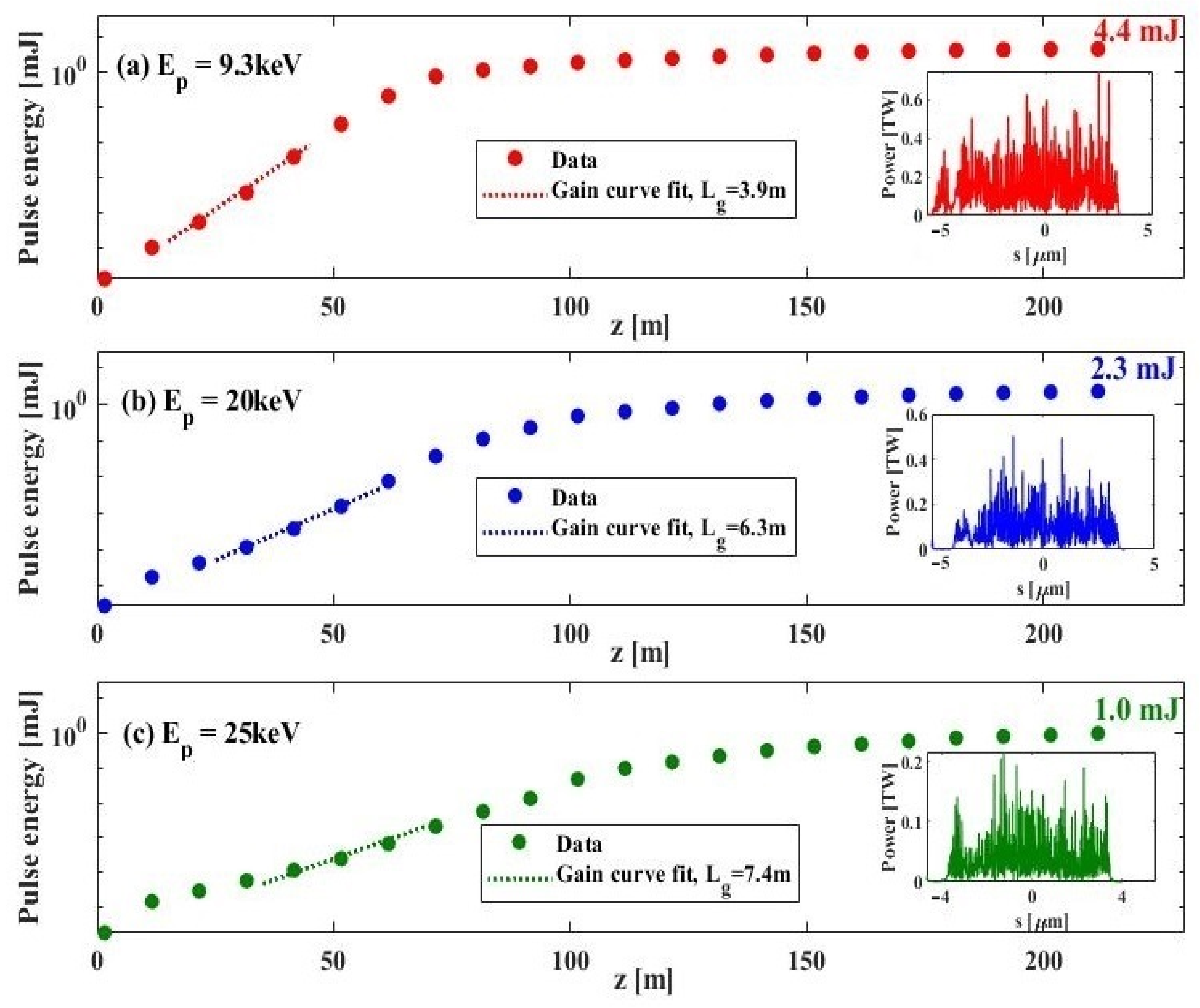
Figure 8 shows the SASE performance of the optimized electron bunch generated with a 56 MV/m cathode accelerating gradient at a final beam energy of 14 GeV. The pulse energy evolution along the undulator beamline is simulated for three photon energies, as shown in (a) 9.3 keV, (b) 20 keV and (c) 25 keV. The inset plots illustrate the SASE power distributions by the end of the undulator beamline. The dashed lines represent exponential fits to the gain curves for estimating the gain length in each case. As shown, at a frequently requested photon energy by the users of 9.3 keV, the SASE intensity can reach about 4.4 mJ with a gain length of less than 4 m. Pushing the photon energy to 20 keV, the bunch still lases with an intensity of 2.3 mJ using a gain length of about 6 m. At 25 keV, that is less than half ångström, millijoule-level SASE intensity can be achieved with about 7 m gain length. It can be seen that, using the low-emittance electron bunch, the facility is capable to provide high-power photon beams above 25 keV using about 80% of the total energy gain available from the accelerator. Note, in addition, that the choice of the accessible photon wavelength is set according to the undulator parameter K via practical gap adjustment for the existing undulators. As a reference, at a frequently requested photon energy of 9.3 keV by the users at an electron beam energy of 14 GeV, the measured gain length is typically about 5 m. Given the room for further improving the bunch quality in the machine, the agreement between the simulated and measured gain lengths can be further improved at this photon energy. However, at other photon energies, especially those above 12 keV, the measurement data are not yet systematically available. A summary of the main results at 14 GeV is given in
Table 1. Note in
Table 1 that the impact of the intersection length between neighbouring undulator sections onto the gain length calculation has been subtracted, and that the numbers given for the power levels by the end of the undulator beamline are corresponding to the peak values of the Gaussian fits to the power distributions as shown in the insets of
Figure 8.
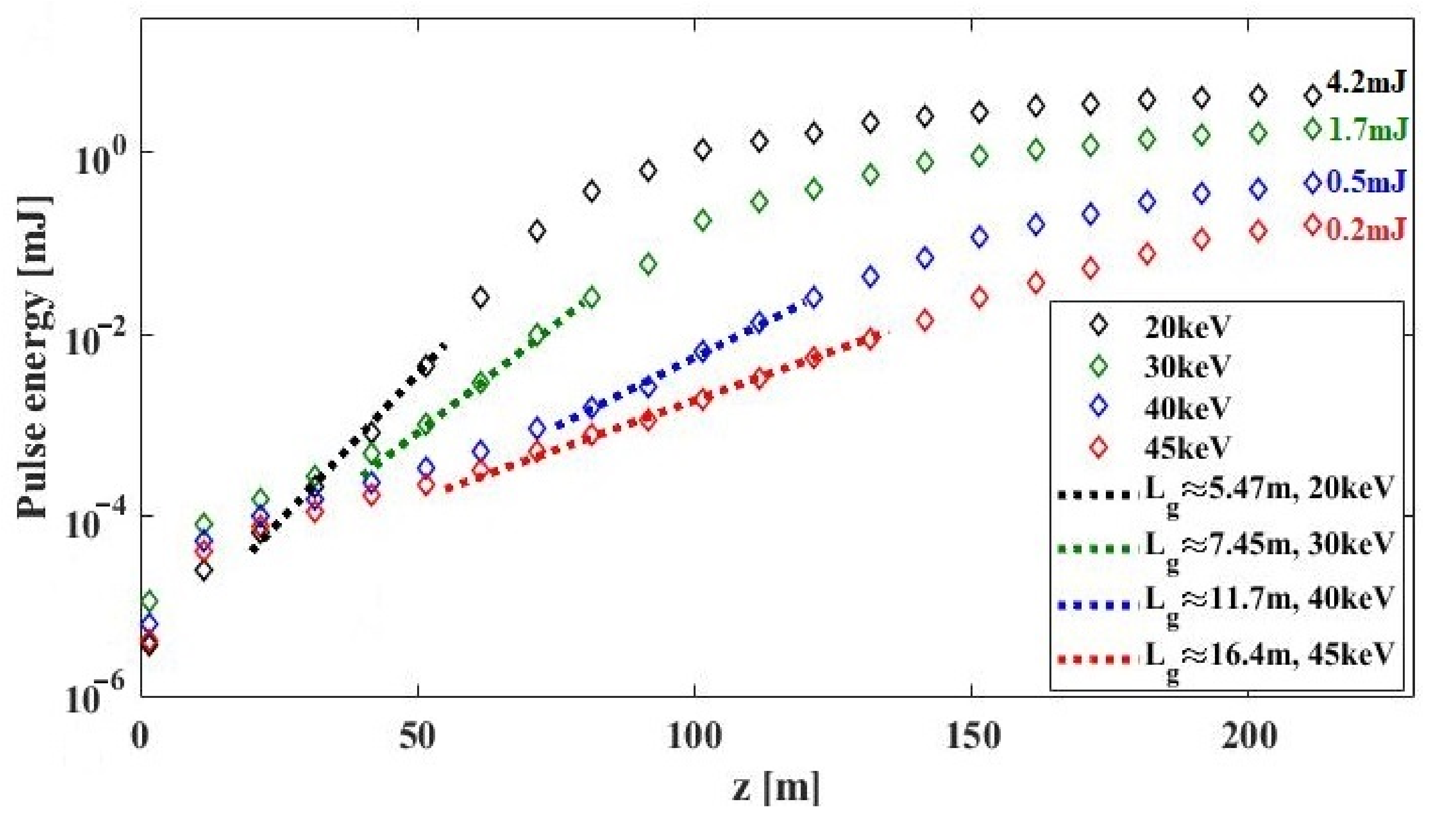
Figure 9 shows the FEL performance in the sub-ångström regime at 17.5 GeV final electron energy by plotting the pulse energy as a function of the longitudinal position along the undulators. The achievable SASE intensity is demonstrated as shortening the photon wavelength from 0.62 Å down to 0.27 Å. The obtained pulse energy by the end of the undulator beamline can reach 4.2 mJ and 1.7 mJ at photon energies of 20 keV and 30 keV, respectively. At 40 keV and 45 keV, still 0.5 mJ and 0.2 mJ SASE intensity can be achieved. The estimated gain length varies from about 5 m at 20 keV to 16 m at 45 keV. As shown, the gain curves for photon energies at/below 40 keV (black, green and blue curves) have stepped into the saturation regime within the total length of the existing undulators. For the case at 45 keV (red curve), a saturation behavior starts to appear at the end of the beamline; however, the gain curve in this case still tends to grow towards higher pulse energy. Note also that the choice of the accessible photon wavelength is set according to the undulator parameter K via practical gap adjustment for the existing undulators. A summary of the main results at 17.5 GeV is given in
Table 2.
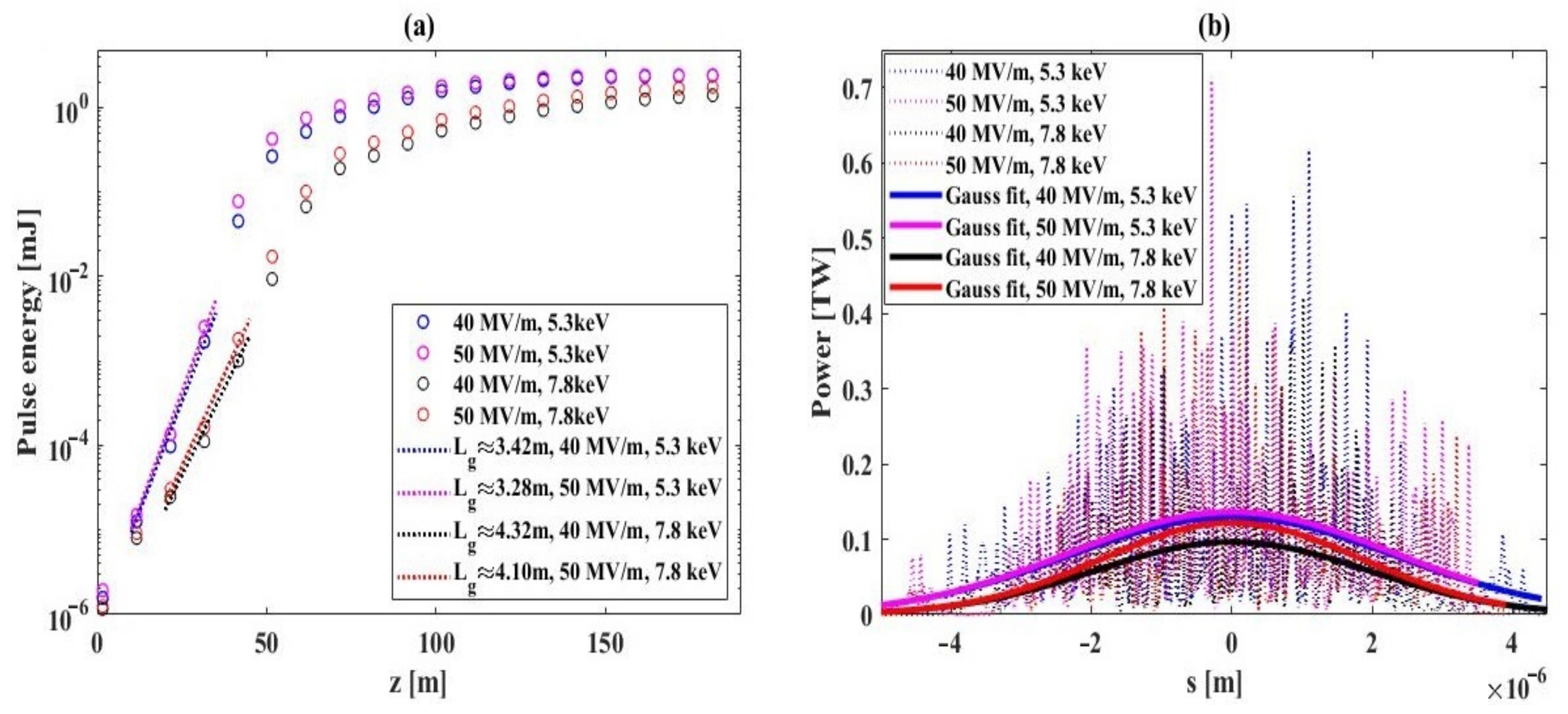
In addition, using 7.3 GeV electron bunches produced with 50 MV/m and 40 MV/m cathode accelerating gradients as presented in
Section 3 and
Section 4,
Figure 10 shows the gain curves of the SASE processes at two exemplary photon energies. As discussed, this is in light of a potential CW operation of the facility. Limited by the present (long) undulator period and a lower electron beam energy in this operation mode, photon energies of 5.3 keV and 7.8 keV, out of the ångström regime, are exemplarily chosen fitting the undulator parameter K via practical gap control. In this work, we only consider existing undulators of the facility aiming to demonstrate the obtained qualities of electron bunches generated at lower cathode accelerating gradients and a reduced final beam energy. As shown in
Figure 10a, the obtained electron bunch qualities in both the 40 MV/m and 50 MV/m cases, enable generating SASE intensities above 1.5 mJ at 7.8 keV and above 2.3 mJ at 5.3 keV. The estimated gain lengths are below 3.5 m and 4.5 m at 5.3 keV and 7.8 keV, respectively. As a comparison, using smaller gain lengths, the 50 MV/m case shows higher SASE pulse energies than 40 MV/m at both photon wavelengths. The superiority of better emittance for the 50 MV/m case over 40 MV/m becomes more pronounced towards higher photon energies, in terms of higher SASE intensity and smaller gain length. At a fixed wavelength the advantage of better emittance for the 50 MV/m case can also be seen in the improved transverse coherence. A summary of the results at 7.3 GeV is presented in
Table 3.
6. Conclusions
Perspectives towards the sub-ångström working regime of the European XFEL are given based on the present state of the facility. Through start-to-end electron bunch optimization for a peak current close to 4 kA by the end of the accelerator beamline, it is demonstrated that a central slice emittance of about 0.24 μm in front of the undulators can be achieved for a 100-pC electron bunch created via photoemission by applying detailed transverse laser pulse shaping and a cathode peak accelerating gradient of about 56 MV/m. The temporal characteristics of the cathode drive laser are kept the same as in current user operation. When reducing the cathode gradient down to 40 MV/m, a central slice emittance of about 0.33 μm is obtained before the undulators.
Based on obtained electron bunch qualities, the FEL performance in the sub-ångström working regime, in terms of SASE pulse intensity and FEL gain length, is discussed at the varied electron beam energy levels available at the facility. Specifically, at 14 GeV electron beam energy, millijoule-level SASE intensity is obtained for a photon energy of 25 keV (i.e. 0.496 Å in wavelength) using a gain length of about 7.4 m. Reference studies were performed, which show that 2.3 mJ and 4.4 mJ lasing intensities at 20 keV and 9.3 keV using gain lengths of 3.9 m and 6.3 m, respectively. Millijoule-level SASE performance can be reached at about 0.5 Å photon wavelength at 14 GeV electron beam energy.
Towards a photon wavelength less than 0.5 Å while boosting the energy level to 17.5 GeV, the obtained electron bunch qualities allow lasing at 30 keV with above 1.5 mJ intensity at a gain length of about 7.5 m. At 40 keV, close to a half-millijoule SASE performance can still be reached. Accessing an even higher photon energy of 45 keV, a fairly good lasing intensity of 0.16 mJ is shown, although the corresponding gain curve just steps into the saturation regime within the available total undulator length of the facility. Note that the existing undulators are used for this study, and that a possible upgrade to superconducting undulators with a controllable undulator period down to 2 cm and below is under consideration, which can further boost the accessible photon energies [
13,
14,
59].
In addition, the obtained electron bunches, produced with lower cathode accelerating gradients of 40 MV/m and 50 MV/m, are used for SASE simulations to demonstrate the bunch qualities at a reduced final beam energy of about 7 GeV. This is relevant to a potential continuous-wave mode operation of the facility. At accessible photon energies using the existing undulators, above 1.5 mJ intensity is obtained at 7.8 keV while more than 2.3 mJ is achieved at 5.3 keV. A higher cathode accelerating gradient of 50 MV/m over 40 MV/m results in a smaller emittance, leading to superior FEL performance. The advantage becomes more pronounced towards higher photon energies.
As an outlook, further developments of the existing cathode laser shaping system are in progress. The measurement programs based on the obtained results as presented in this article are currently under active discussion and dedicated facility developments at the European XFEL in the sub-ångström working regime are planned.


