
Comparative Aerodynamic Performance Analysis of Camber Morphing and Conventional Airfoils


Abstract
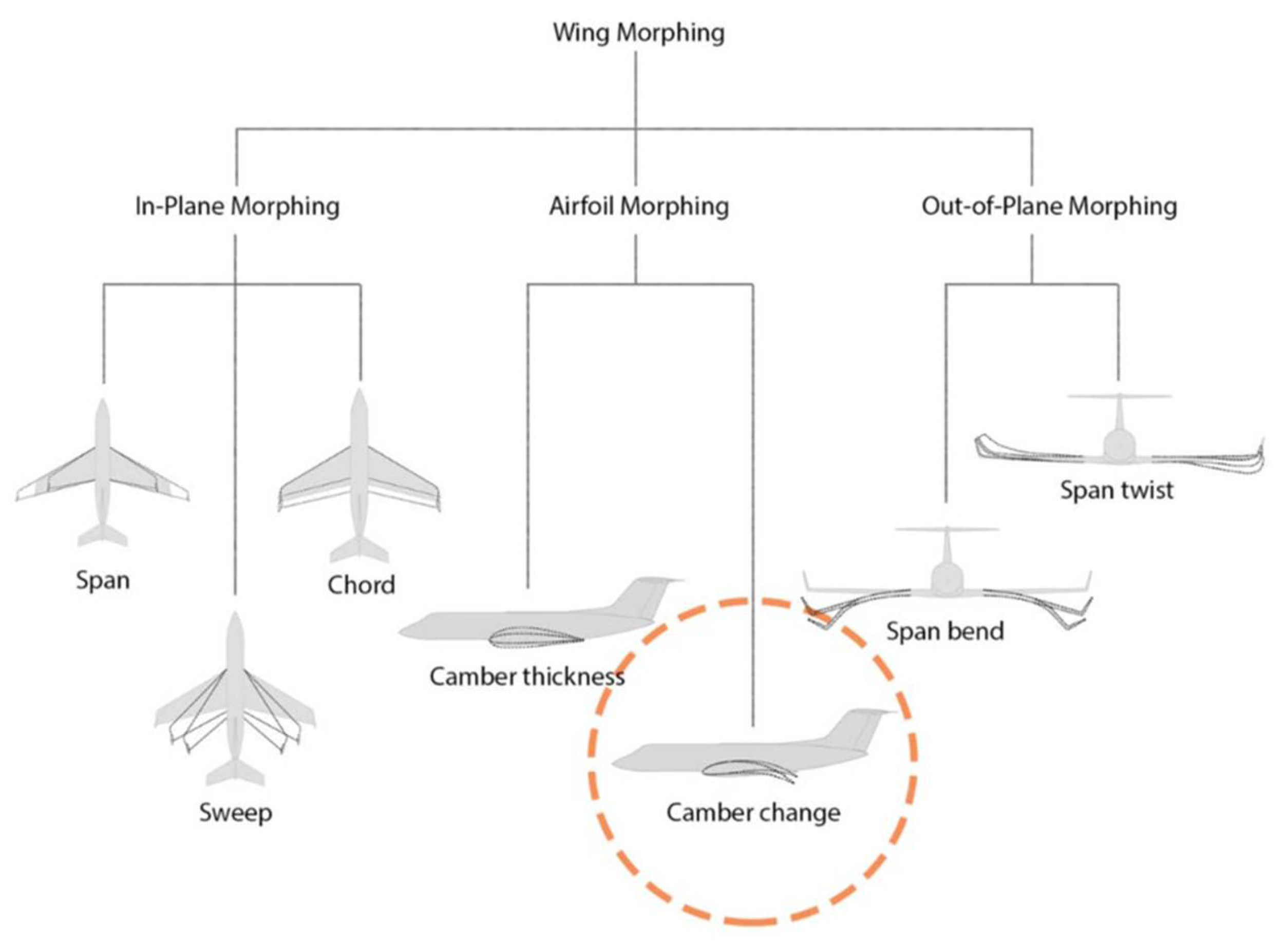
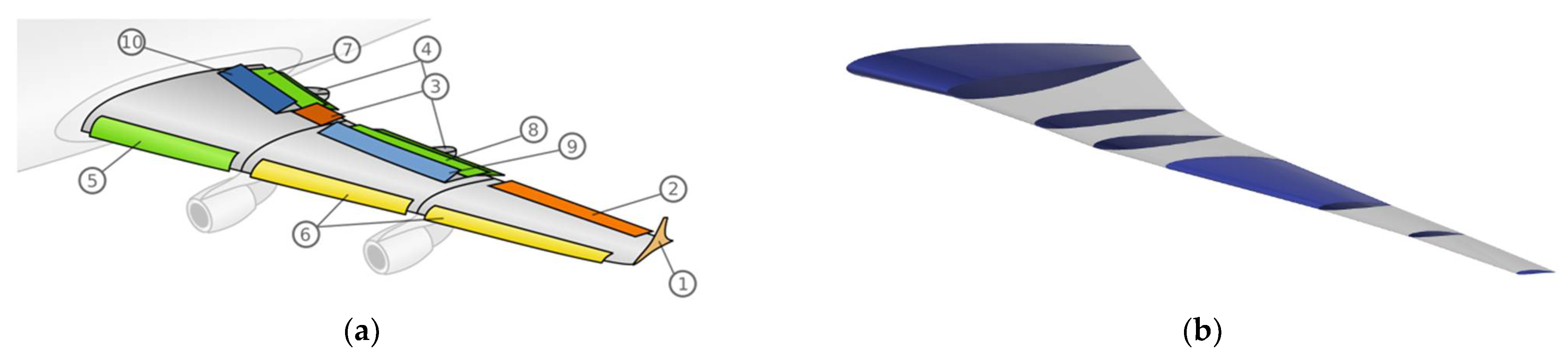
:1. Introduction
2. Problem Statement
3. Methodology
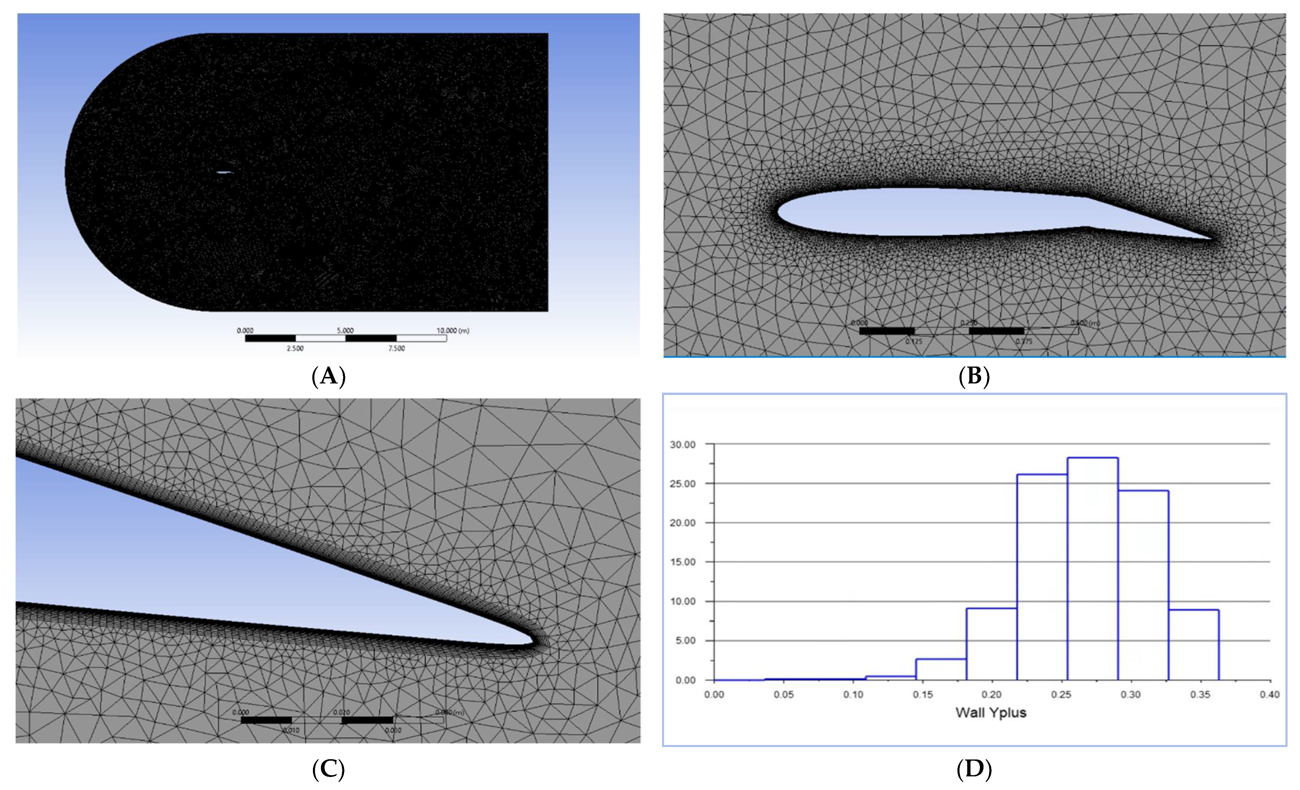
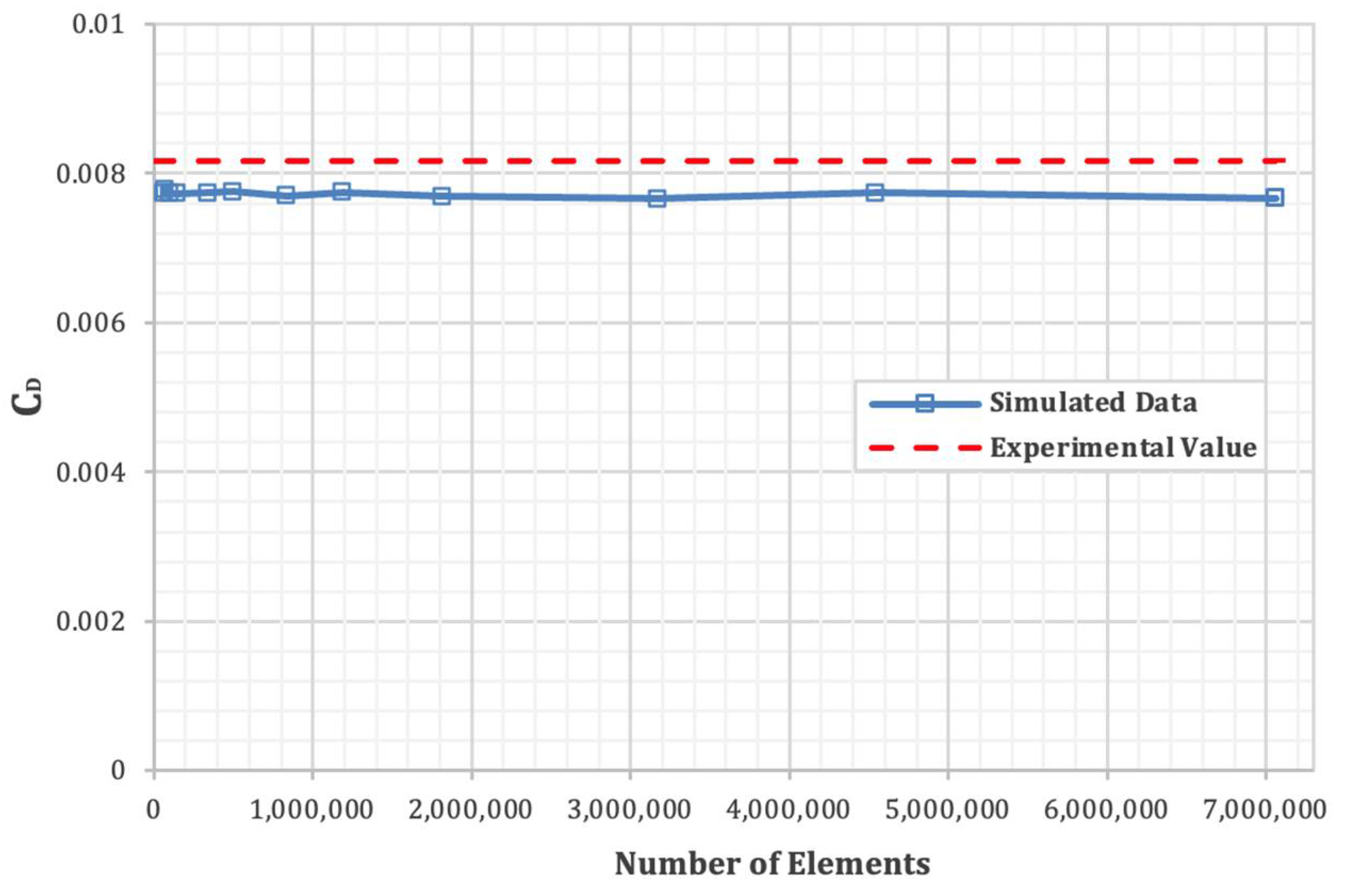
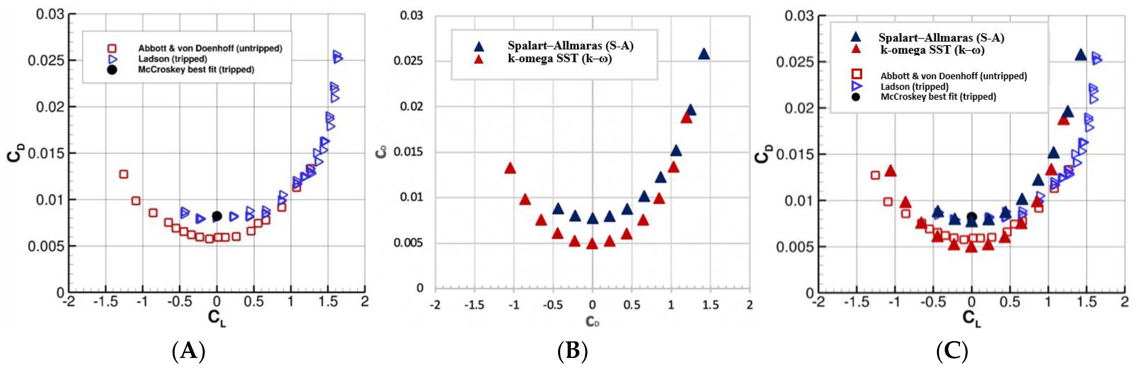
3.1. Computational Method and Verification
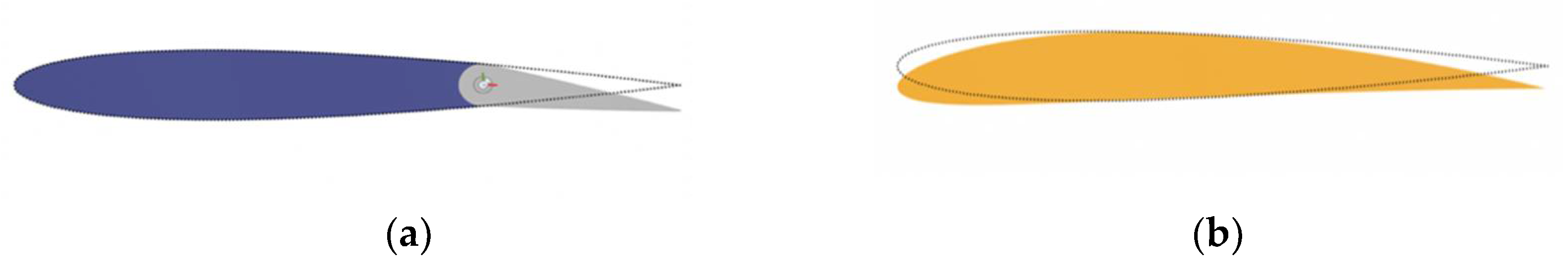
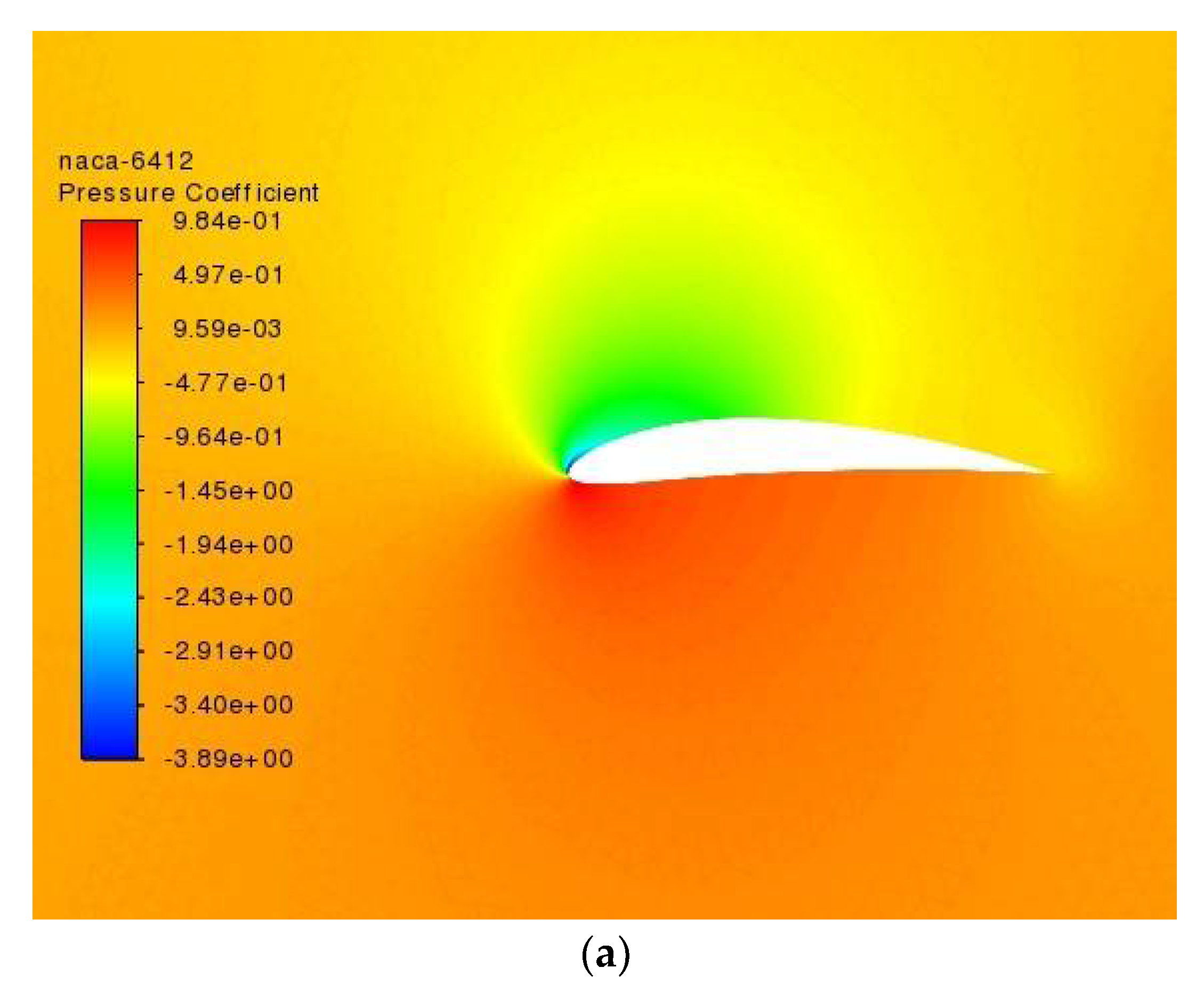
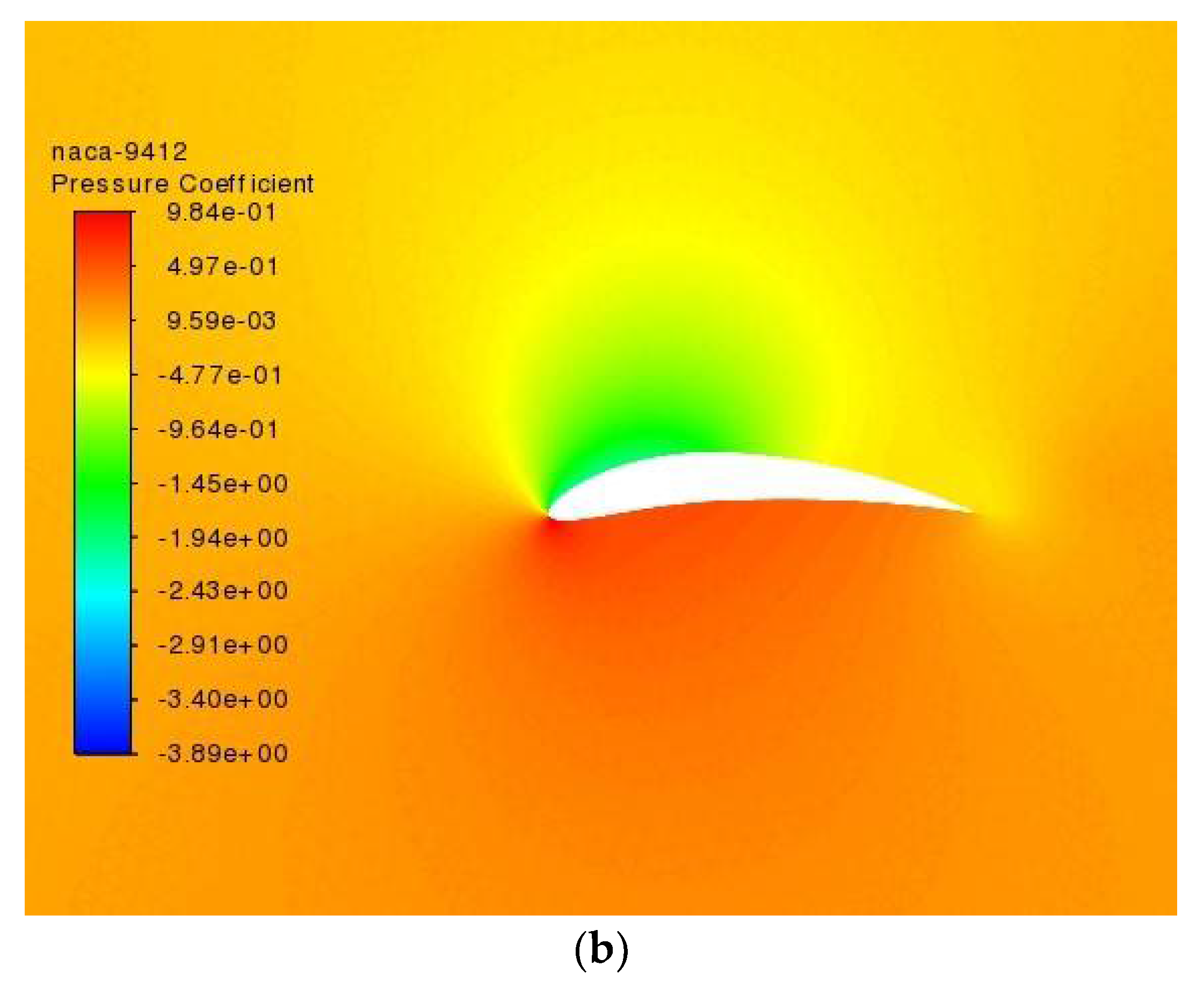
3.2. Airfoil Geometry Configuartion
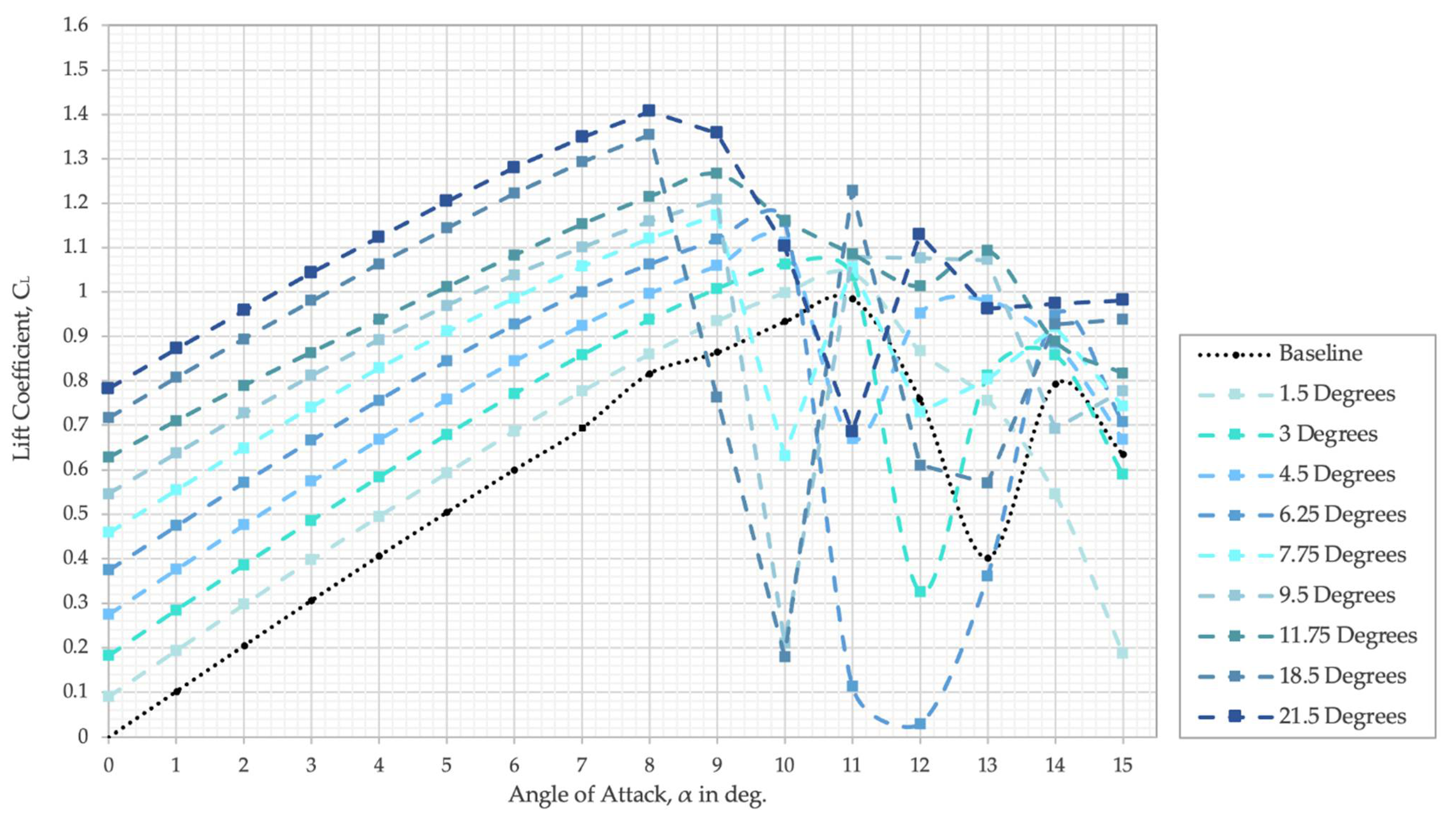
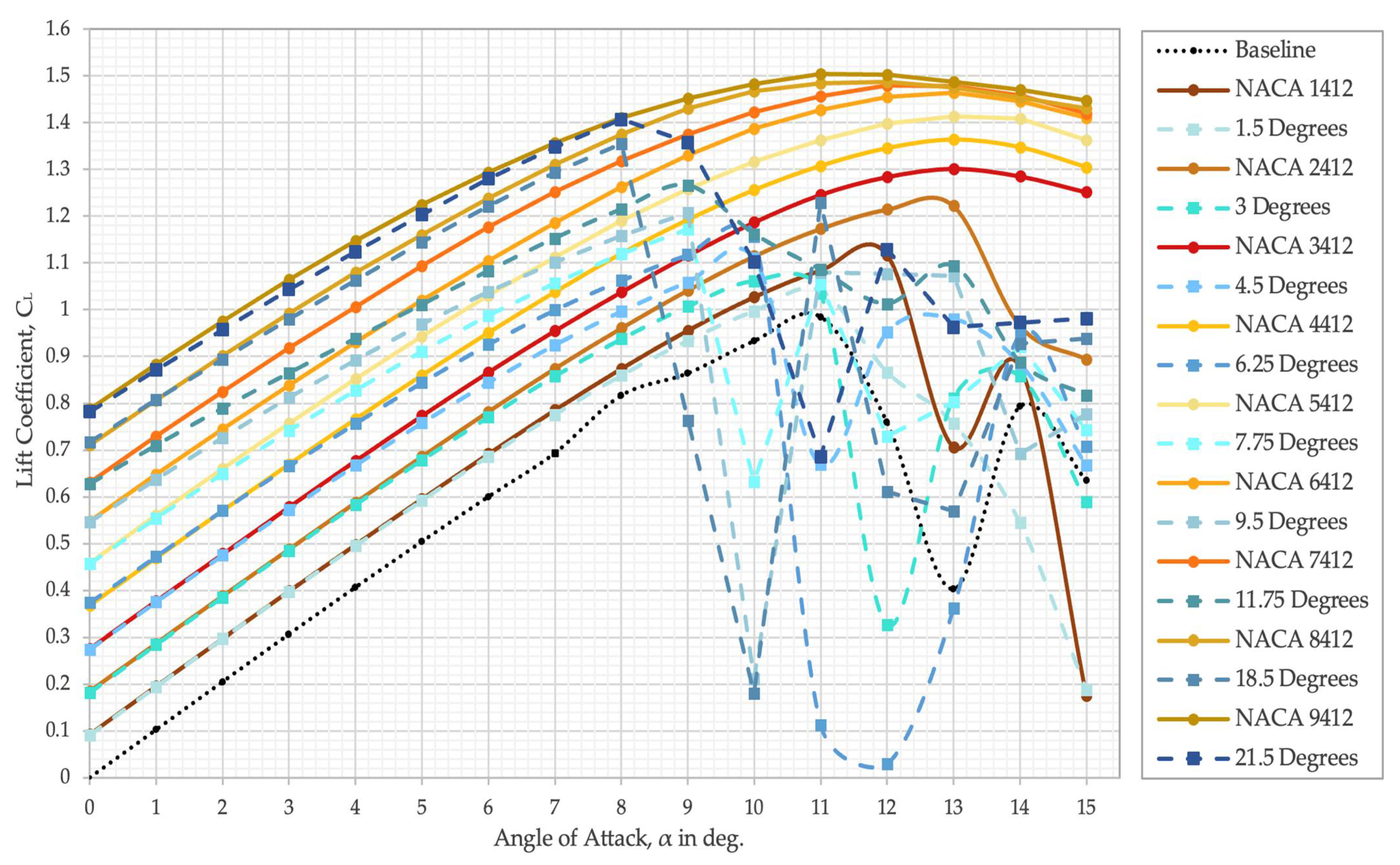
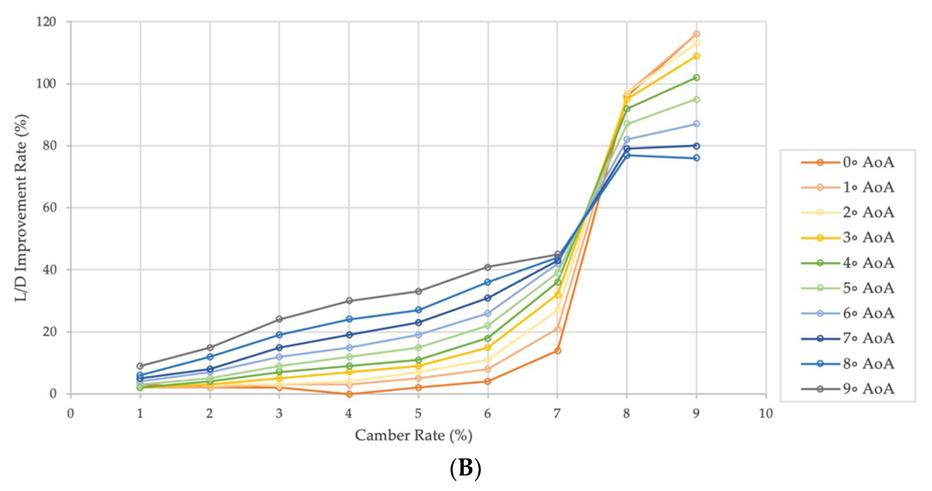
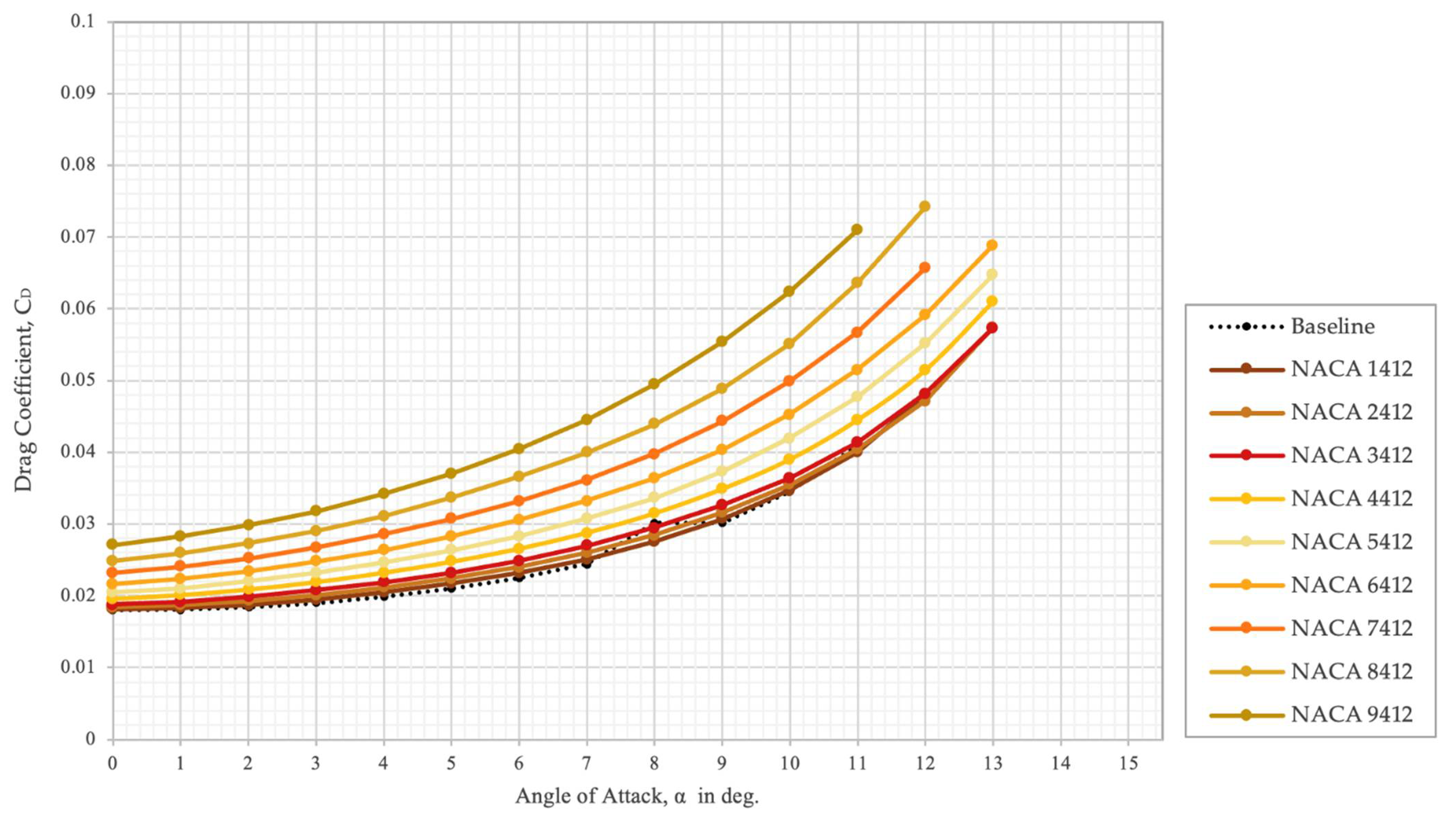
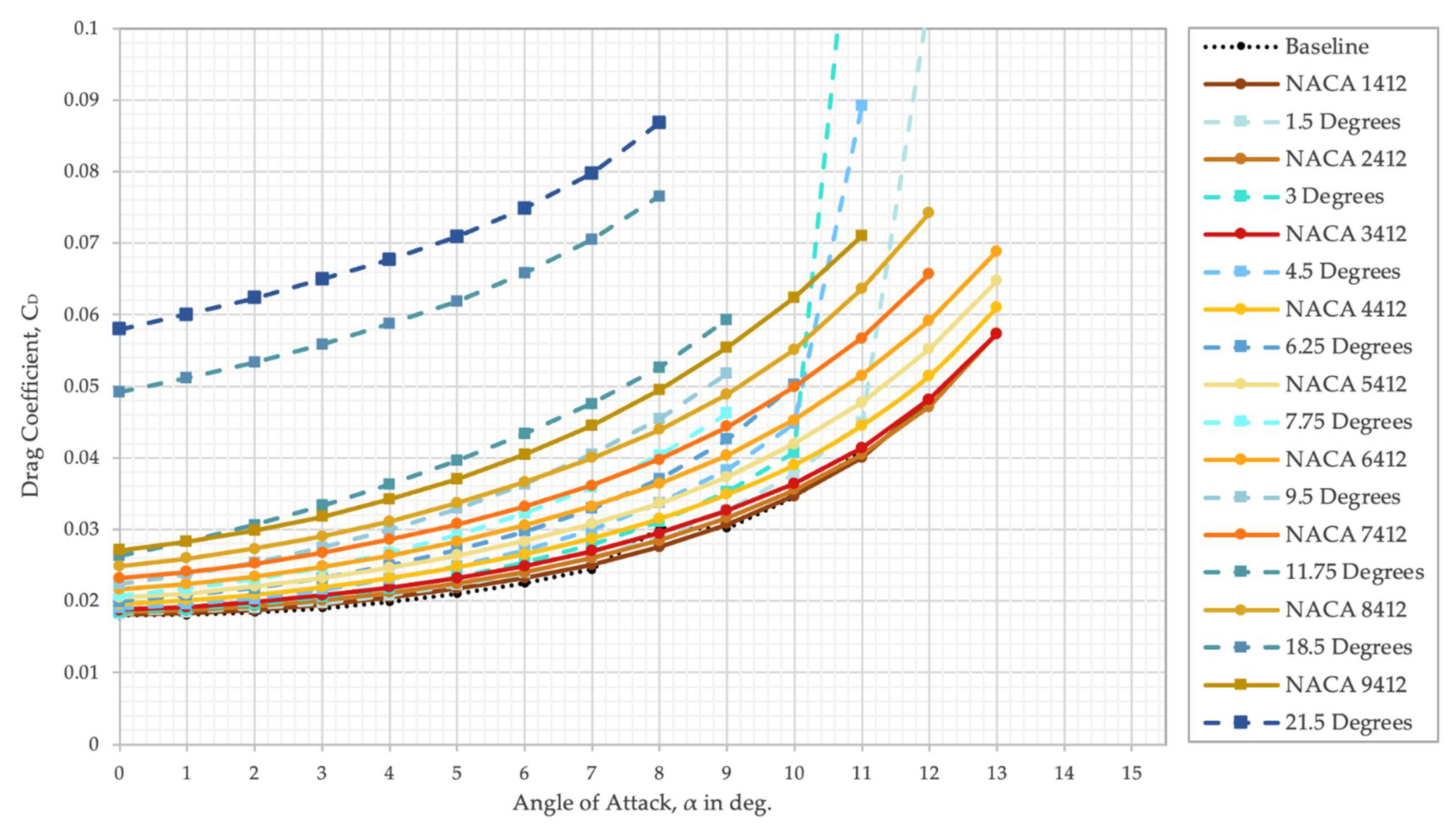
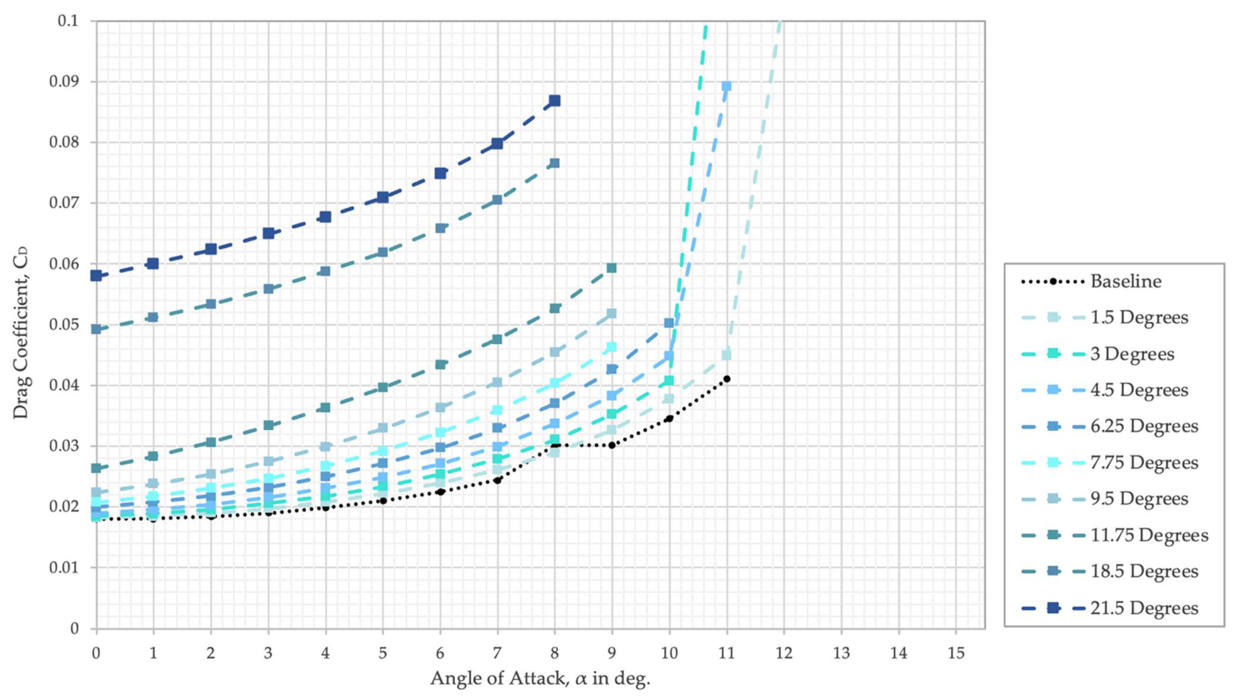
4. Results
5. Conclusions
Author Contributions
Funding
Institutional Review Board Statement
Informed Consent Statement
Data Availability Statement
Acknowledgments
Conflicts of Interest
Nomenclature
| L | Lift force |
| D | Drag force |
| Angle of attack | |
| CL | Lift coefficient |
| CD | Drag coefficient |
| y | First layer thickness |
| Re | Reynolds number |
| Skin-friction coefficient | |
| Dynamic viscosity | |
| Air density | |
| Air velocity | |
| Spalart–Allmaras working variable |
Abbreviations
| CFD | Computational fluid dynamics |
| CAD | Computer-aided design |
| L/D | Lift-to-drag ratio |
| RANS | Reynolds-averaged Navier–Stokes |
| S-A | Spalart–Allmaras |
| UAV | Unmanned aerial vehicle |
| MAV | Micro air vehicle |
| NACA | National Advisory Committee for Aeronautics |
References
- Barbarino, S.; Bilgen, O.; Ajaj, R.M.; Friswell, M.; Inman, D.J. A Review of Morphing Aircraft. J. Intell. Mater. Syst. Struct. 2011, 22, 823–877. [Google Scholar] [CrossRef]
- La, S.; Joe, W.Y.; Akbar, M.; Alsaidi, B. Surveys on skin design for morphing wing aircraft: Status and challenges. In Proceedings of the 2018 AIAA Aerospace Sciences Meeting, Kissimmee, FL, USA, 8–12 January 2018; p. 0315. [Google Scholar]
- Nordmann, A. Control Surfaces on Airfoil. Available online: https://commons.wikimedia.org/wiki/File:Control_surfaces_on_airfoil.svg (accessed on 12 October 2012).
- Campanile, L.; Sachau, D. The belt-rib concept: A structronic approach to variable camber. J. Intell. Mater. Syst. Struct. 2000, 11, 215–224. [Google Scholar] [CrossRef]
- Keidel, D.; Sodja, J.; Werter, N.; de Breuker, R.; Ermanni, P. Development and testing of an unconventional morphing wing concept with variable chord and camber. In Proceedings of the 26th International Conference on Adaptive Structures and Technologies, Kobe, Japan, 25 October 2015; pp. 1–12. [Google Scholar]
- Zhang, P.; Zhou, L.; Cheng, W.; Qiu, T. Conceptual Design and Experimental Demonstration of a Distributedly Actuated Morphing Wing. J. Aircr. 2015, 52, 452–461. [Google Scholar] [CrossRef]
- Li, H.; Liu, L.; Xiao, T.; Ang, H. Design and simulative experiment of an innovative trailing edge morphing mechanism driven by artificial muscles embedded in skin. Smart Mater. Struct. 2016, 25, 095004. [Google Scholar] [CrossRef]
- Molinari, G.; Quack, M.; Arrieta, A.F.; Morari, M.; Ermanni, P. Design, realization and structural testing of a compliant adaptable wing. Smart Mater. Struct. 2015, 24, 105027. [Google Scholar] [CrossRef]
- Maki, M. Experimental Study of a Morphing Wing Configuration with Multi-Slotted Variable-Camber Mechanism. In Proceedings of the AIAA Atmospheric Flight Mechanics Conference, Washington, DC, USA, 13–17 June 2016; p. 3849. [Google Scholar]
- Maute, K.; Reich, G.W. Integrated Multidisciplinary Topology Optimization Approach to Adaptive Wing Design. J. Aircr. 2006, 43, 253–263. [Google Scholar] [CrossRef]
- Sun, J.; Guan, Q.; Liu, Y.; Leng, J. Morphing aircraft based on smart materials and structures: A state-of-the-art review. J. Intell. Mater. Syst. Struct. 2016, 27, 2289–2312. [Google Scholar] [CrossRef]
- Li, D.; Zhao, S.; Da Ronch, A.; Xiang, J.; Drofelnik, J.; Li, Y.; Zhang, L.; Wu, Y.; Kintscher, M.; Monner, H.P.; et al. A review of modelling and analysis of morphing wings. Prog. Aerosp. Sci. 2018, 100, 46–62. [Google Scholar] [CrossRef] [Green Version]
- Dhileep, K.; Kumar, D.; Ghosh, S.; Faruque Ali, S. Numerical Study of Camber Morphing in NACA0012 Airfoil. In Proceedings of the AIAA AVIATION 2020 FORUM, Online, 15–19 June 2020; p. 2781. [Google Scholar]
- Kumar, D.; Ali, S.F.; Arockiarajan, A. Structural and Aerodynamics Studies on Various Wing Configurations for Morphing. IFAC-PapersOnLine 2018, 51, 498–503. [Google Scholar] [CrossRef]
- Zhang, J.; Shaw, A.D.; Wang, C.; Gu, H.; Amoozgar, M.; Friswell, M.I.; Woods, B.K. Aeroelastic model and analysis of an active camber morphing wing. Aerosp. Sci. Technol. 2021, 111, 106534. [Google Scholar] [CrossRef]
- Bishay, P.L.; Finden, R.; Recinos, S.; Alas, C.; Lopez, E.; Aslanpour, D.; Flores, D.; Gonzalez, E. Development of an SMA-based camber morphing UAV tail core design. Smart Mater. Struct. 2019, 28, 075024. [Google Scholar] [CrossRef]
- Kang, W.-R.; Kim, E.-H.; Jeong, M.-S.; Lee, I.; Ahn, S.-M. Morphing Wing Mechanism Using an SMA Wire Actuator. Int. J. Aeronaut. Space Sci. 2012, 13, 58–63. [Google Scholar] [CrossRef] [Green Version]
- Basaeri, H.; Yousefi-Koma, A.; Zakerzadeh, M.R.; Mohtasebi, S.S. Experimental study of a bio-inspired robotic morphing wing mechanism actuated by shape memory alloy wires. Mechatronics 2014, 24, 1231–1241. [Google Scholar] [CrossRef]
- Yokozeki, T.; Sugiura, A.; Hirano, Y. Development of Variable Camber Morphing Airfoil Using Corrugated Structure. J. Aircr. 2014, 51, 1023–1029. [Google Scholar] [CrossRef] [Green Version]
- Meguid, S.A.; Su, Y.; Wang, Y. Complete morphing wing design using flexible-rib system. Int. J. Mech. Mater. Des. 2017, 13, 159–171. [Google Scholar] [CrossRef]
- Communier, D.; Botez, R.M.; Wong, T. Design and Validation of a New Morphing Camber System by Testing in the Price—Païdoussis Subsonic Wind Tunnel. Aerospace 2020, 7, 23. [Google Scholar] [CrossRef] [Green Version]
- Wu, R.; Soutis, C.; Zhong, S.; Filippone, A. A morphing aerofoil with highly controllable aerodynamic performance. Aeronaut. J. 2017, 121, 54–72. [Google Scholar] [CrossRef] [Green Version]
- Vasista, S.; Tong, L. Topology-Optimized Design and Testing of a Pressure-Driven Morphing-Aerofoil Trailing-Edge Structure. AIAA J. 2013, 51, 1898–1907. [Google Scholar] [CrossRef]
- Meyer, P.; Lück, S.; Spuhler, T.; Bode, C.; Hühne, C.; Friedrichs, J.; Sinapius, M. Transient Dynamic System Behavior of Pressure Actuated Cellular Structures in a Morphing Wing. Aerospace 2021, 8, 89. [Google Scholar] [CrossRef]
- Woods, B.K.; Bilgen, O.; Friswell, M. Wind tunnel testing of the fish bone active camber morphing concept. J. Intell. Mater. Syst. Struct. 2014, 25, 772–785. [Google Scholar] [CrossRef]
- Zhang, Y.; Ge, W.; Zhang, Z.; Mo, X.; Zhang, Y. Design of compliant mechanism-based variable camber morphing wing with nonlinear large deformation. Int. J. Adv. Robot. Syst. 2019, 16, 1729881419886740. [Google Scholar] [CrossRef]
- Molinari, G.; Arrieta, A.F.; Guillaume, M.; Ermanni, P. Aerostructural Performance of Distributed Compliance Morphing Wings: Wind Tunnel and Flight Testing. AIAA J. 2016, 54, 3859–3871. [Google Scholar] [CrossRef] [Green Version]
- Chanzy, Q.; Keane, A. Analysis and experimental validation of morphing UAV wings. Aeronaut. J. 2018, 122, 390–408. [Google Scholar] [CrossRef] [Green Version]
- Keidel, D.; Fasel, U.; Molinari, G.; Ermanni, P. Design, Development, and Structural Testing of a Camber-Morphing Flying Wing Airplane. In Smart Materials, Adaptive Structures and Intelligent Systems; American Society of Mechanical Engineers: New York, NY, USA, 2017; Volume 58264, p. V002T04A013. [Google Scholar]
- Zhao, A.; Zou, H.; Jin, H.; Wen, D. Structural design and verification of an innovative whole adaptive variable camber wing. Aerosp. Sci. Technol. 2019, 89, 11–18. [Google Scholar] [CrossRef]
- Fasel, U.; Keidel, D.; Baumann, L.; Cavolina, G.; Eichenhofer, M.; Ermanni, P. Composite additive manufacturing of morphing aerospace structures. Manuf. Lett. 2020, 23, 85–88. [Google Scholar] [CrossRef]
- Alsulami, A.; Akbar, M.; Joe, W.Y. A Comparative Study: Aerodynamics of Morphed Airfoils Using CFD Techniques and Analytical Tools. In ASME International Mechanical Engineering Congress and Exposition; American Society of Mechanical Engineers: New York, NY, USA, 2017; Volume 58349, p. V001T03A010. [Google Scholar]
- Cheung, K.; Cellucci, D.; Copplestone, G.; Cramer, N.; Fusco, J.; Jenett, B.; Kim, J.; Langford, A.; Mazhari, A.; Trinh, G.; et al. Development of Mission Adaptive Digital Composite Aerostructure Technologies (MADCAT). In Proceedings of the 17th AIAA Aviation Technology, Integration, and Operations Conference, Denver, CO, USA, 5–9 June 2017; p. 4273. [Google Scholar]
- Kudva, J.N. Overview of the DARPA Smart Wing Project. J. Intell. Mater. Syst. Struct. 2004, 15, 261–267. [Google Scholar] [CrossRef]
- Kota, S.; Osborn, R.; Ervin, G.; Maric, D.; Flick, P.; Paul, D. Mission adaptive compliant wing–design, fabrication and flight test. In RTO Applied Vehicle Technology Panel (AVT) Symposium; RTO-MP-AVT-168; NATO-OTAN: Evora, Portugal, 2009; p. 18-1. [Google Scholar]
- Vasista, S.; Riemenschneider, J.; Van De Kamp, B.; Monner, H.P.; Cheung, R.C.M.; Wales, C.; Cooper, J.E. Evaluation of a Compliant Droop-Nose Morphing Wing Tip via Experimental Tests. J. Aircr. 2017, 54, 519–534. [Google Scholar] [CrossRef] [Green Version]
- Nguyen, N.; Lebofsky, S.; Ting, E.; Kaul, U.; Chaparro, D.; Urnes, J. Development of Variable Camber Continuous Trailing Edge Flap for Performance Adaptive Aeroelastic Wing. In SAE AeroTech Congress & Exhibition; SAE International: Washington, DC, USA, 2015. [Google Scholar]
- Kumar, T.R.S.; Venugopal, S.; Ramakrishnananda, B.; Vijay, S. Aerodynamic Performance Estimation of Camber Morphing Airfoils for Small Unmanned Aerial Vehicle. J. Aerosp. Technol. Manag. 2020, 12, 1420. [Google Scholar] [CrossRef]
- Huntley, S.J.; Woods, B.K.; Allen, C.B. Computational Analysis of the Aerodynamics of Camber Morphing. In Proceedings of the AIAA Aviation 2019 Forum, Dallas, TX, USA, 17–21 June 2019; p. 2914. [Google Scholar]
- Alulema, V.H.; Valencia, E.; Pillajo, D.; Jacome, M.; Lopez, J.; Ayala, B. Degree of Deformation and Power Consumption of Compliant and Rigid-linked Mechanisms for Variable-Camber Morphing Wing UAVs. In Proceedings of the AIAA Propulsion and Energy 2020 Forum, Virtual Event, 24–28 August 2020; p. 3958. [Google Scholar]
- Taguchi, K.; Fukunishi, K.; Takazawa, S.; Sunada, Y.; Imamura, T.; Rinoie, K.; Yokozeki, T. Experimental Study about the Deformation and Aerodynamic Characteristics of the Passive Morphing Airfoil. Trans. Jpn. Soc. Aeronaut. Space Sci. 2020, 63, 18–23. [Google Scholar] [CrossRef] [Green Version]
- Spalart, P.; Allmaras, S. A one-equation turbulence model for aerodynamic flows. In Proceedings of the 30th Aerospace Sciences Meeting and Exhibit, Reno, NV, USA, 6–9 January 1992; p. 439. [Google Scholar]
- Goetten, F.; Finger, D.; Marino, M.; Bil, C.; Havermann, M.; Braun, C. A review of guidelines and best practices for subsonic aerodynamic simulations using RANS CFD. In APISAT 2019: Asia Pacific International Symposium on Aerospace Technology; Engineers Gold Coast: Burleigh Heads, QLD, Australia, 2019; p. 227. [Google Scholar]
- Schlichting, H.; Kestin, J. Boundary Layer Theory; Springer: Berlin/Heidelberg, Germany, 1961. [Google Scholar]
- Ladson, C.L. Effects of Independent Variation of Mach and Reynolds Numbers on the Low-Speed Aerodynamic Characteristics of the NACA 0012 Airfoil Section; National Aeronautics and Space Administration, Scientific and Technical Information Division: Washington, DC, USA, 1988. [Google Scholar]
- 2D NACA 0012 Airfoil Validation Case. Available online: https://turbmodels.larc.nasa.gov/naca0012numerics_val.html (accessed on 20 October 2021).
- Airfoil Tools. Available online: http://airfoiltools.com/airfoil/naca4digit (accessed on 20 October 2021).
- Ohtake, T.; Nakae, Y.; Motohashi, T. Nonlinearity of the aerodynamic characteristics of NACA0012 aerofoil at low Reynolds numbers. Jpn. Soc. Aeronaut. Space Sci. 2007, 55, 439–445. [Google Scholar]


| Matching Cases | Morphing Airfoils | Conventional Airfoils | Overlapping Region | ||
|---|---|---|---|---|---|
| Maximum Camber Rate (%) | Stall Angle (°) | Flap Deflection Angle (°) | Stall Angle (°) | ||
| Baseline | NACA 0012—0% | 11° | 0° | 11° | All angles |
| Case 1 | NACA 1412—1% | 11.8° | 1.5° | 11° | 10 angles |
| Case 2 | NACA 2412—2% | 12.6° | 3° | 10.6° | 9 angles |
| Case 3 | NACA 3412—3% | 13° | 4.5° | 10° | 7 angles |
| Case 4 | NACA 4412—4% | 13° | 6.25° | 9° | 5 angles |
| Case 5 | NACA 5412—5% | 13° | 7.75° | 9° | 4 angles |
| Case 6 | NACA 6412—6% | 13° | 9.5° | 9° | 3 angles |
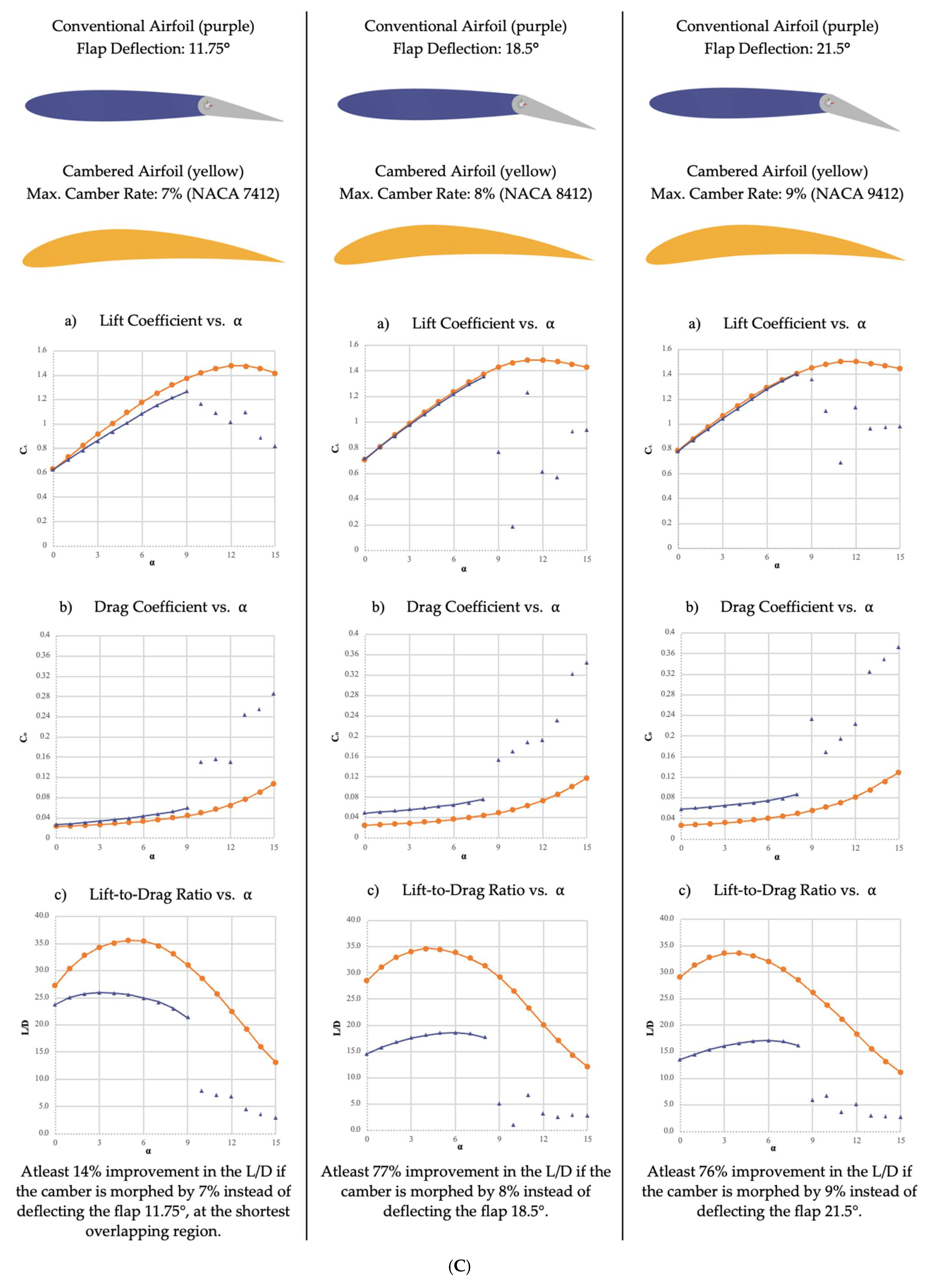
| Case 7 | NACA 7412—7% | 12° | 11.75° | 9° | 2 angles |
| Case 8 | NACA 8412—8% | 12° | 18.5° | 8° | 8 angles |
| Case 9 | NACA 9412—9% | 11° | 21.5° | 8° | 9 angles |
| L/D | Percentage Improvement | L/D | Percentage Improvement | L/D | Percentage Improvement | ||||
|---|---|---|---|---|---|---|---|---|---|
| NACA 1412 | 1.5° | Case 1 | NACA 2412 | 3° | Case 2 | NACA 3412 | 4.5° | Case 3 | |
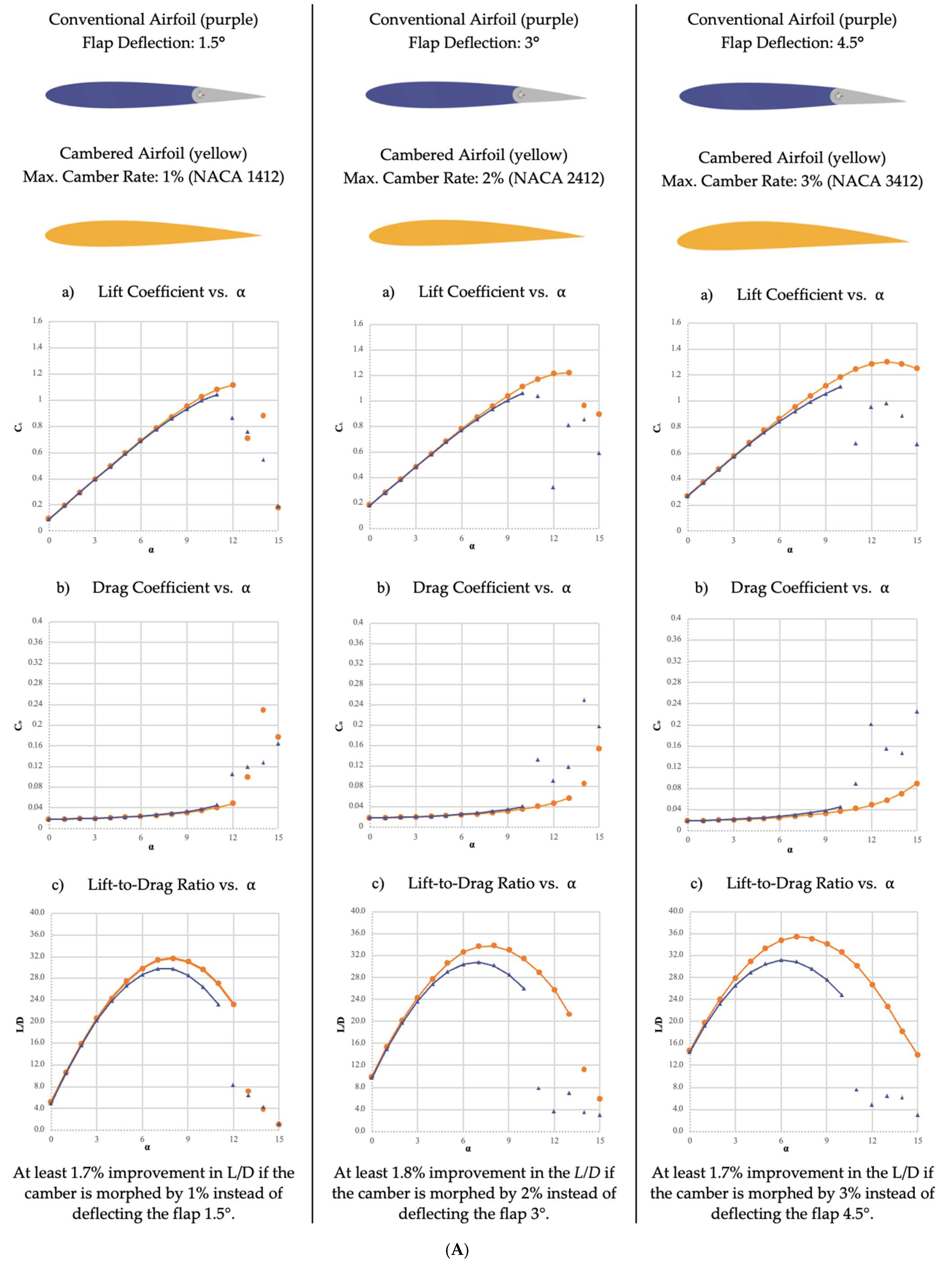
| 0 | 5.1 | 5.0 | 3.4% | 10.0 | 9.8 | 1.8% | 14.7 | 14.4 | 1.7% |
| 1 | 10.7 | 10.5 | 2.2% | 15.3 | 15.0 | 2.1% | 19.7 | 19.2 | 2.8% |
| 2 | 15.9 | 15.6 | 1.7% | 20.2 | 19.7 | 2.5% | 24.0 | 23.3 | 3.2% |
| 3 | 20.5 | 20.1 | 1.7% | 24.3 | 23.6 | 2.9% | 27.9 | 26.6 | 4.9% |
| 4 | 24.3 | 23.8 | 2.2% | 27.8 | 26.9 | 3.5% | 31.0 | 29.0 | 7.0% |
| 5 | 27.4 | 26.7 | 2.8% | 30.6 | 29.1 | 5.1% | 33.3 | 30.5 | 9.4% |
| 6 | 29.8 | 28.7 | 3.8% | 32.6 | 30.4 | 7.3% | 34.9 | 31.2 | 11.8% |
| 7 | 31.3 | 29.8 | 5.1% | 33.7 | 30.8 | 9.2% | 35.5 | 30.9 | 14.9% |
| 8 | 31.7 | 29.8 | 6.5% | 33.8 | 30.2 | 11.8% | 35.2 | 29.6 | 18.7% |
Publisher’s Note: MDPI stays neutral with regard to jurisdictional claims in published maps and institutional affiliations. |
© 2021 by the authors. Licensee MDPI, Basel, Switzerland. This article is an open access article distributed under the terms and conditions of the Creative Commons Attribution (CC BY) license (https://creativecommons.org/licenses/by/4.0/).
Share and Cite
Majid, T.; Jo, B.W. Comparative Aerodynamic Performance Analysis of Camber Morphing and Conventional Airfoils. Appl. Sci. 2021, 11, 10663. https://doi.org/10.3390/app112210663
Majid T, Jo BW. Comparative Aerodynamic Performance Analysis of Camber Morphing and Conventional Airfoils. Applied Sciences. 2021; 11(22):10663. https://doi.org/10.3390/app112210663
Chicago/Turabian StyleMajid, Tuba, and Bruce W. Jo. 2021. "Comparative Aerodynamic Performance Analysis of Camber Morphing and Conventional Airfoils" Applied Sciences 11, no. 22: 10663. https://doi.org/10.3390/app112210663
APA StyleMajid, T., & Jo, B. W. (2021). Comparative Aerodynamic Performance Analysis of Camber Morphing and Conventional Airfoils. Applied Sciences, 11(22), 10663. https://doi.org/10.3390/app112210663