Article

Study on the Earth Pressure during Sinking Stage of Super Large Caisson Foundation

1
State Key Laboratory of Geomechanics and Geotechnical Engineering, Institute of Rock and Soil Mechanics, Chinese Academy of Sciences, Wuhan 430071, China
2
University of Chinese Academy of Sciences, Beijing 100049, China
*
Author to whom correspondence should be addressed.
Appl. Sci. 2021, 11(21), 10488; https://doi.org/10.3390/app112110488
Submission received: 30 September 2021 / Revised: 3 November 2021 / Accepted: 4 November 2021 / Published: 8 November 2021
(This article belongs to the Special Issue Advances in Geotechnical Engineering Ⅱ)

Abstract

:
End resistance is a dominant variable in the sinking process of super-sized caisson foundation, which is of great importance to the safe sinking of the caisson foundation. Based on soil excavation process of super large caisson foundation of the main tower of Changtai Yangtze River Bridge, the distribution characteristics and variation of earth pressure under the foot blade was analyzed using 3D finite element method at the first stage of soil excavation. Furthermore, the earth pressure was monitored in real time during soil excavation in order to analyze the influence of soil excavation process on the distribution of earth pressure. The analysis results of engineering practice showed that in the process of soil excavation from inner area to outer area, the end resistance of inner bulkhead and inner partition walls decreased, while the end resistance of outer bulkhead and outer partition walls gradually increased till the soil reached the failure state in the outer bulkhead area. The distribution characteristics and variation of the earth pressure can really reflect overall stress state of caisson foundation, which helps guide the safe sinking by soil excavation.

1. Introduction

In recent years, with the development of economy and transportation construction, the number of bridge planning and construction in China is increasing, and the bridge span is constantly refreshing the world record. Caisson foundation has the advantages of high bearing capacity, good integrity, big stiffness, and small area occupancy [1]. Therefore, it is widely used in large-scale bridge construction. With the requirement improvement of bearing capacity and settlement of large-sized bridge engineering, the caisson foundation is developing towards to large size and deep sinking elevation. Ensuring the safe sinking has been the key issue to sinking construction of caisson foundation. The distribution characteristics of end resistance is different from that of small and medium-sized caisson foundation, which inevitably caused different controlling method of sinking construction for different size caisson foundation [2]. However, at present, the sinking construction of caisson foundation by soil excavation mostly depends on engineering experience, the distribution of earth pressure is not clear during soil excavation, which caused poor controllability of sinking process [3,4,5]. The soil excavation only relying on engineering experience has seriously affected the safety of the sinking construction and the reliability of caisson foundation structure, and the sinking process by soil excavation needs to be further studied.
The distribution of the sinking resistance can reflect the whole stress state of caisson foundation. The sinking resistance is an important basis to make soil excavation scheme, and the earth pressure at the foot blade is the key factor to study the sinking resistance of caisson foundation. Based on the slip line field theory, Yan et al. [6] established an approximate calculation model of the ultimate soil resistance of caisson foundation during sinking and derived the calculation formulas of the ultimate bearing capacity for plane strain problem and axisymmetric problem. Xu, et al. [7] used similar methods to determine the distribution characteristics of earth pressure of the annular caisson foundation, which was verified by engineering examples. Jiang, et al. [8] analyzed the sinking process of caisson foundation of Hutong Yangtze River bridge by conventional model test and obtained the earth pressure distribution of foot blade during the sinking process. Zhou, et al. [9], studied the earth pressure under the foot blade by the centrifugal model test, and found that the ratio of earth pressure almost keeps constant between horizontal position and the oblique position of the foot blade. Besides, the field measurement of earth pressure was used to draw the time-history curve in order to analyze the distribution of sinking resistance and the sinking behavior of caisson foundation by many scholars [2,10,11,12]. Zhang, et al. [13] and Mu, et al. [14], focused on the mechanism of sudden sinking of caisson foundation and found that the earth pressure at the foot blade will significantly decrease before sudden sinking of caisson foundation. At present, most existing studies focused on end resistance of small and medium-sized caisson foundation, while there are few studies on that of large or super large caisson foundation. Qin, et.al. [15] pointed out that with the continuous increase of the scale of caisson foundation, the ratio of end resistance and side friction resistance has gradually become the controlling factor to safe sinking of caisson foundation. For small or medium-sized caisson foundation, the side friction resistance played a leading role in the sinking process, which is not possibly suitable for large or super-large caisson foundation.
In this paper, the variation characteristics of end resistance by soil excavation was studied based on soil excavation process of super large caisson foundation of the main tower of Changtai Yangtze River Bridge. The transfer variation of end resistance in different areas at the bottom of caisson foundation was revealed, which helps guide the soil excavation process to ensure the safety of sinking process. Besides, the research results can also be used to predict the sinking amount of similar large caisson foundation for reference.

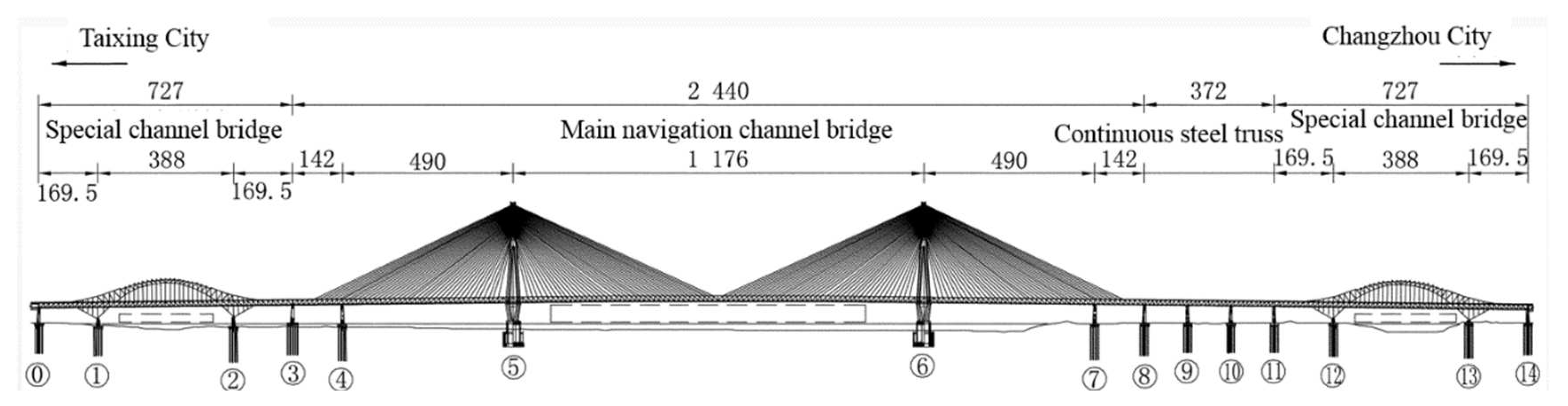
2. Overview of Changtai Yangtze River Bridge

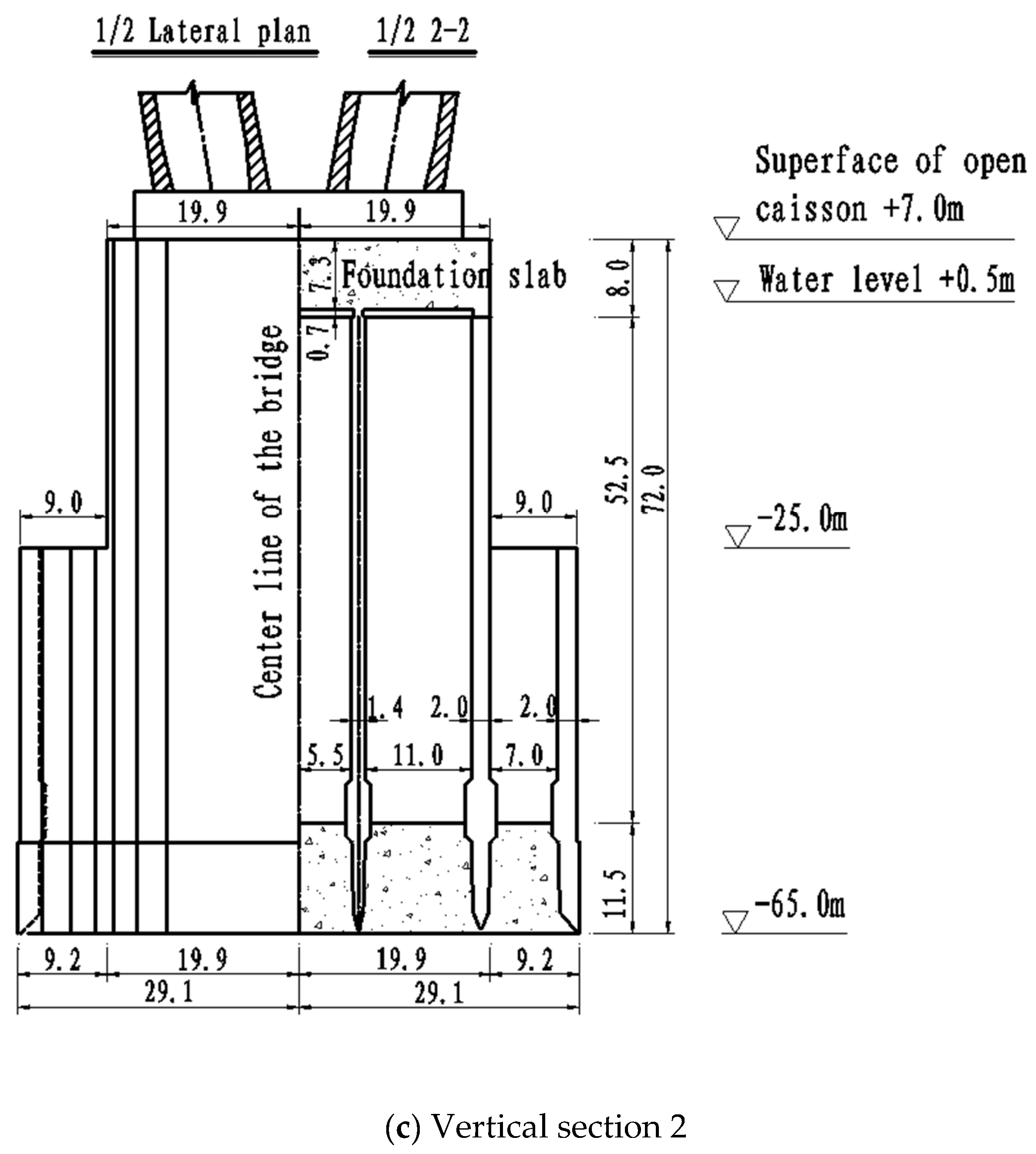
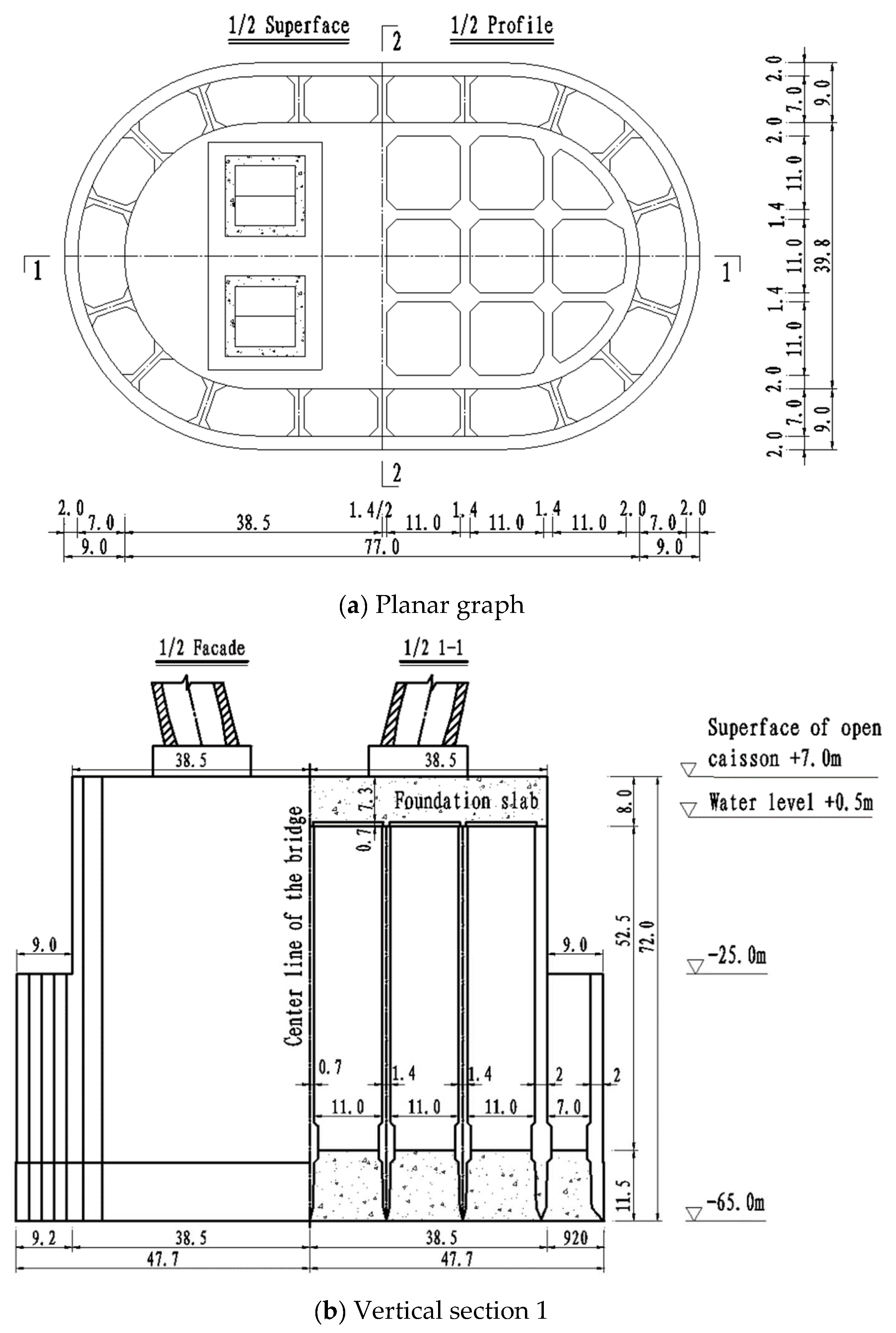
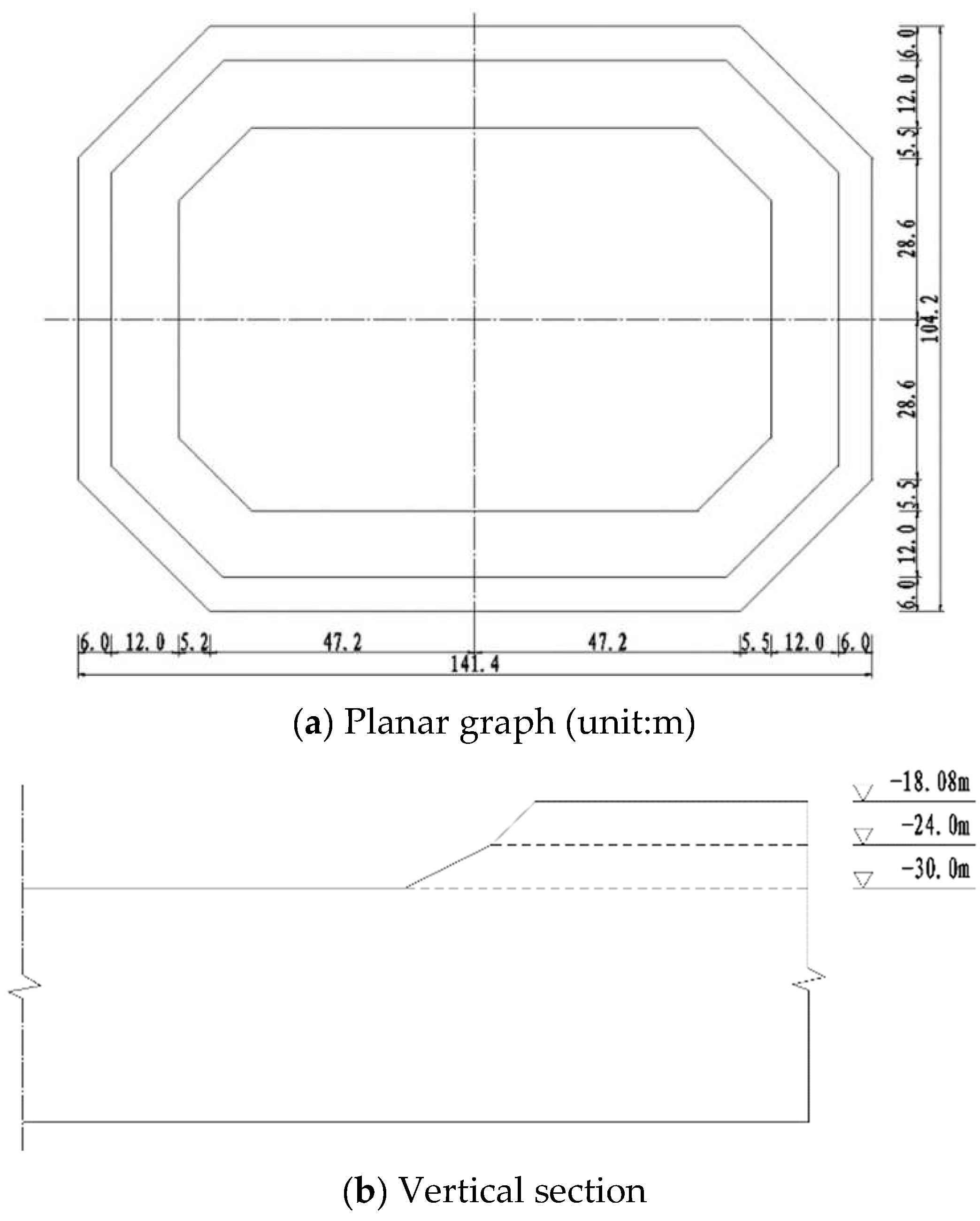
2.1. General Description

Changtai Yangtze River Bridge connects Changzhou City and Taixing City and is a rail-cum-road cable-stayed bridge with asymmetric layout of double towers and double cable planes. The upper layer of the bridge is a two-way six lane expressway, and the lower layer is an intercity railway and a two-way four lane ordinary road. With a main span of 1176 m, the main navigational channel bridge is the largest cable-stayed bridge in the world and the overall layout is shown in Figure 1 [15,16].
The round end plane shape was also adopted under the main tower of Changtai Yangtze River bridge. Moreover, the stepped caisson foundation was created with small top and large bottom shape. For the stepped caisson foundation, the bottom surface is 95 m long cross the bridge, 57.8 m wide along the bridge, and the radius is 28.9 m for the circular end. For the top surface, it is 77 m long, 39.8 m wide, and the radius is 19.9 m for the circular end (Figure 2). The total height of the caisson foundation is 72 m, of which the lower step is 43 m, the upper step is 29 m, and the target sinking elevation is −65 m. For the caisson foundation, the steel shell concrete is used from top to bottom, which is the largest underwater steel caisson foundation in the world. The caisson foundation contains 36 compartments, including 18 inner compartments and 18 outer compartments. The names of four typical areas are shown in Figure 3, and they are respectively inner partition wall, inner bulkhead, outer partition wall and outer bulkhead.

2.2. Geological Conditions

The caisson foundation was prefabricated on the shore and floated to the target position, where the water level is 0.5 m. After implantation by water injection, the steel shell heightening, concrete pouring and soil excavation was carried out in phases and the target sinking elevation is −65 m. At the target position, the stratum is shown in Table 1. And the bearing stratum of caisson foundation is dense medium fine sand. The soil parameters in Table 1 are from the report of engineering geological exploration, in which the strength parameters are from the shear tests in door, and the deformation modules are from the compression tests and consolidation tests in door. Prior to the implantation of caisson foundation, the soil on the riverbed was pre excavated, which formed an underwater slope. The shape and size of the underwater slope are shown in Figure 4.

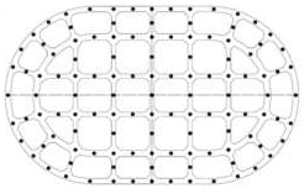
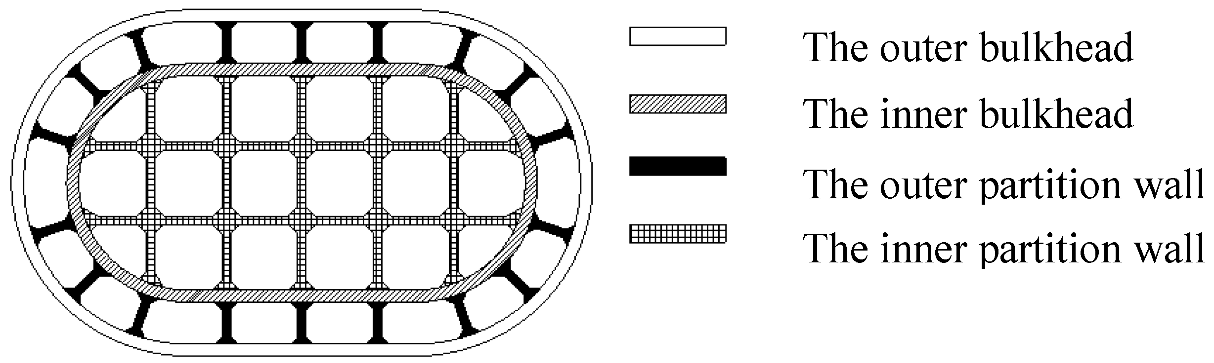
2.3. Sensor Arrangement

The earth pressure at the foot blade can directly reflect the stress characteristics at the bottom of the caisson foundation, which is of great significance to analyze, predict and guide the sinking construction of the caisson foundation. For the earth pressure, a total of 119 earth pressure cells were arranged at the bottom of the foot blade, of which 36 sensors were located in the outer bulkhead, 18 sensors in the outer partition wall, 28 sensors in the inner bulkhead and 37 sensors in the inner partition wall. The arrangement of sensors was shown in Figure 5, in which solid dot represent earth pressure sensors. The earth pressure cells were installed on the tread of the foot blade, which was typically shown as Figure 6. Therefore, the total vertical stress can be obtained in real time during soil excavation process.

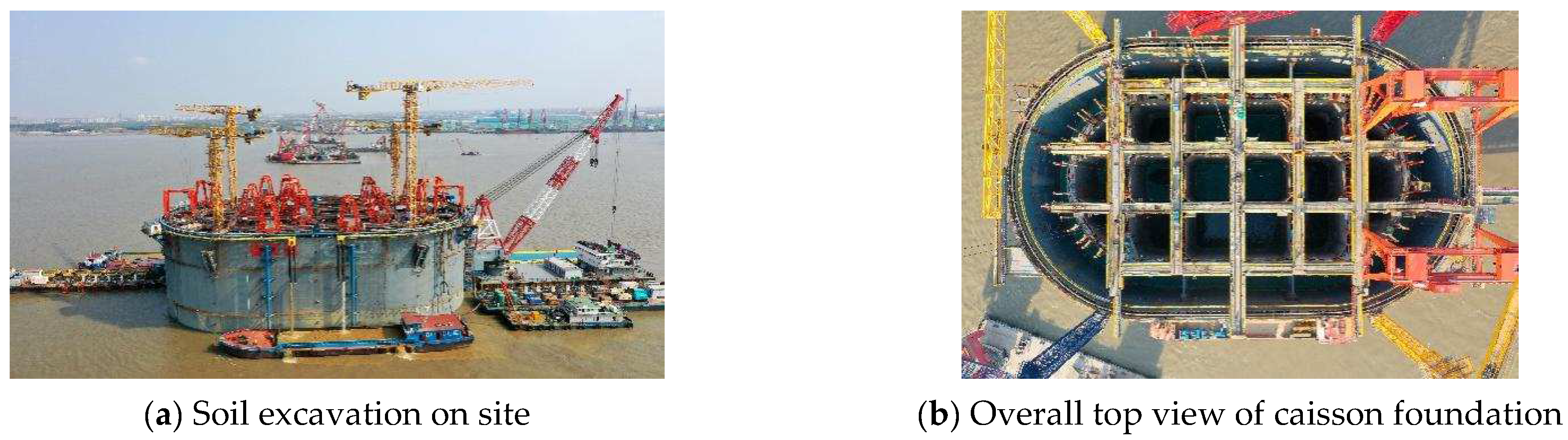
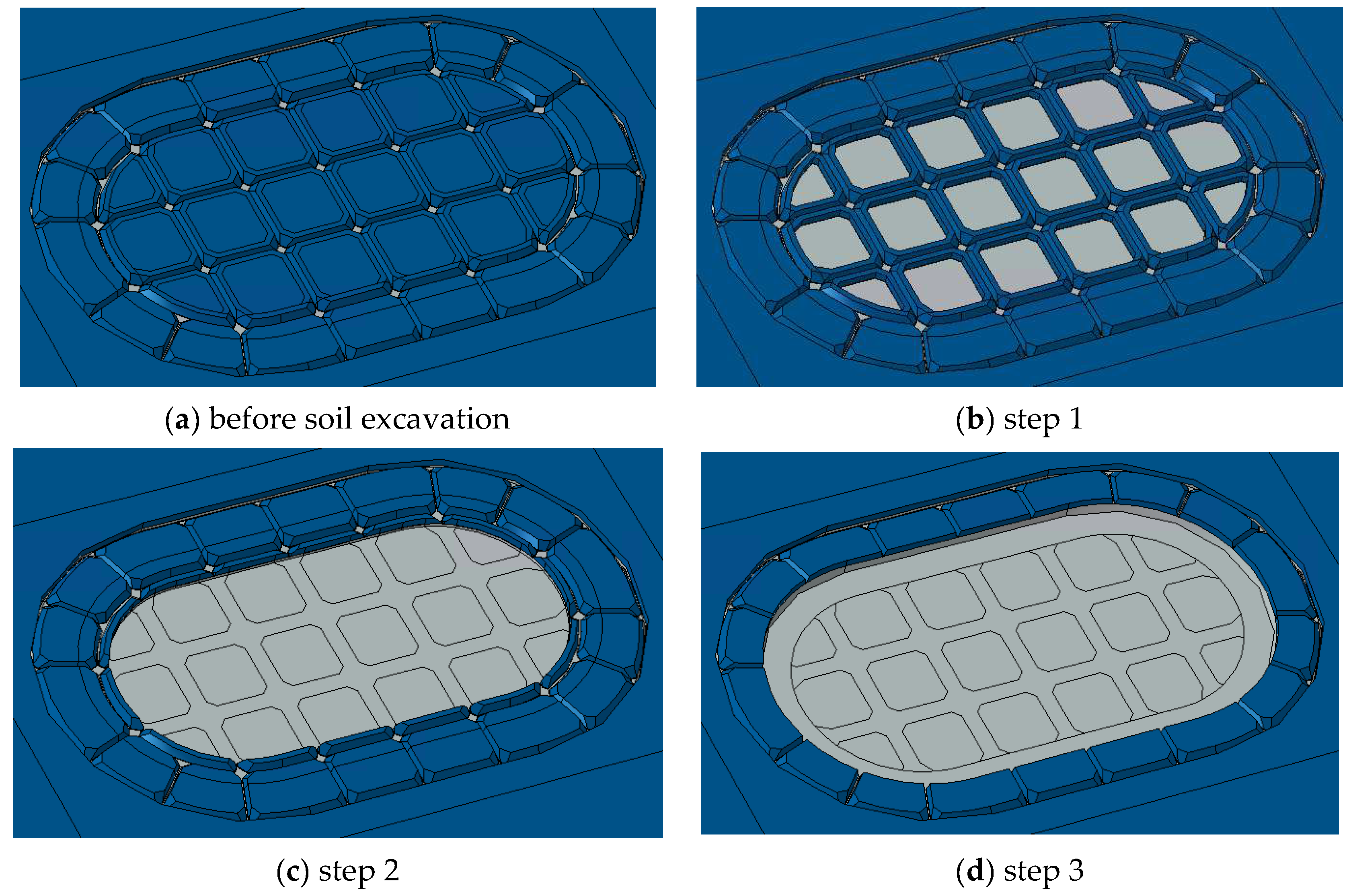
2.4. Soil Excavation Procedure

The soil excavation directly influenced the sinking safety of caisson foundation, so, random soil excavation is not permitted in the sinking construction of large caisson foundation. For the caisson foundation of Changtai Yangtze River bridge, the soil excavation was carried out according to the principle as the follows, the soil is excavated from the inner compartment to external compartment. Moreover, the soil is removed from inside the compartment to the blind area of the foot blade. Besides, uniform and symmetrical soil excavation was required, and the deviation should be timely corrected. Figure 7 showed soil excavation in the field. Before the soil excavation, the elevation of mud surface is −30 m and the bottom elevation of outer bulkhead is −31.85 m. After soil excavation at the first stage, the elevation of mud surface is −32.85 m. The soil excavation procedure was described in Figure 8 and Table 2 at the first sinking stage of caisson foundation.
The sinking resistance during the sinking process of caisson foundation includes end resistance and side friction resistance. The variation of earth pressure at the foot blade during sinking process of the caisson foundation was only focused on in this paper, As is known, at the first sinking stage of caisson foundation, the side friction resistance is close to 0, which will gradually increase with the sinking process, however, it is not easy to definitely determine the side friction resistance at certain sinking elevation. Therefore, in order to greatly reduce the influence of side friction resistance, the first sinking stage was only studied from the mud surface elevation −30.0 m to the elevation −31.85 m.

3. 3-D Finite Element Numerical Analysis

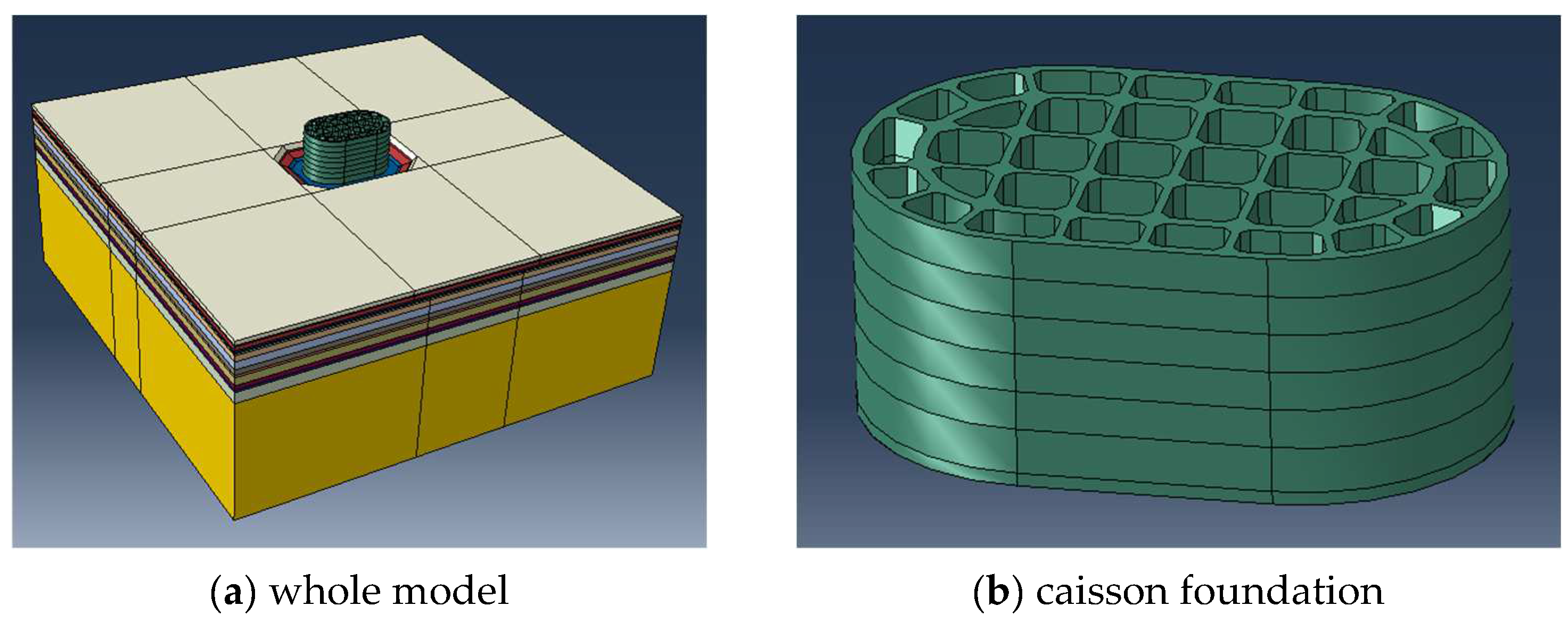
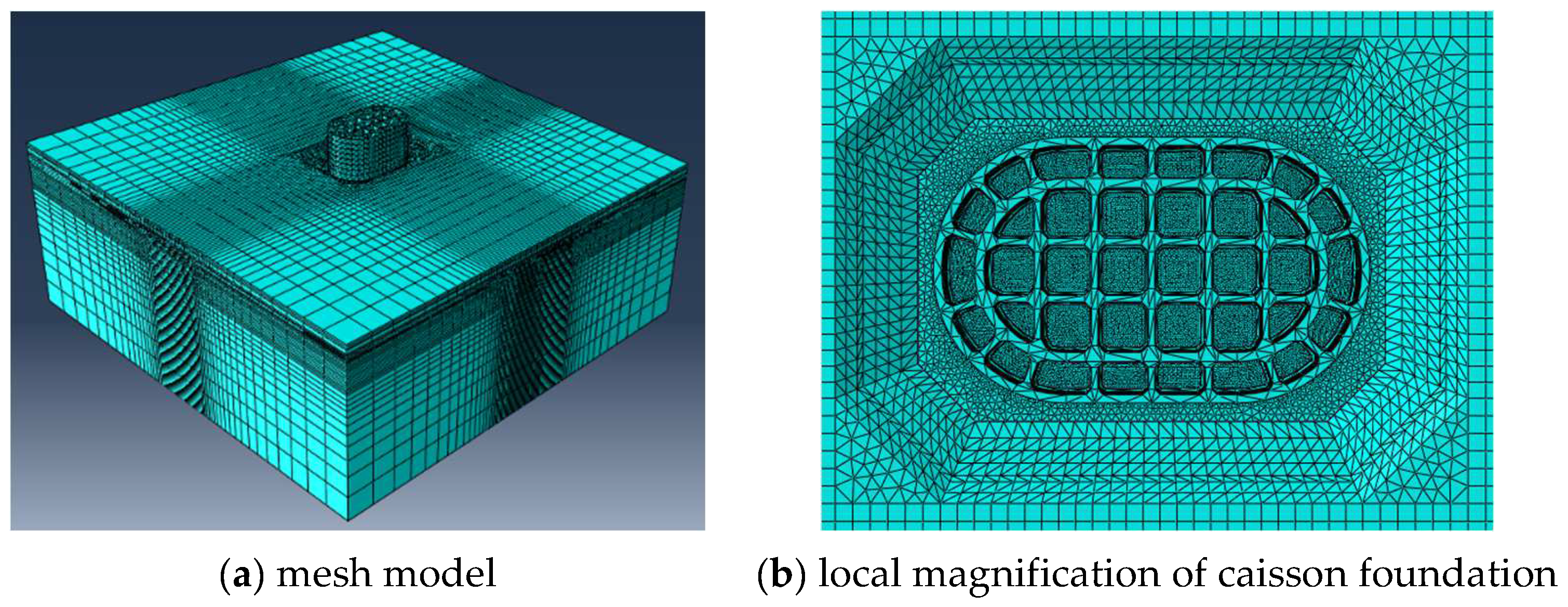
3.1. 3-D Calculating Model

In this paper, the sinking process was simulated by 3-D finite element method with software ABAQUS during soil excavation. Based on actual size of caisson foundation and stratum in the target position, the 3-D calculating model was established. The overall height of the caisson foundation is 51 m before the first stage of soil excavation. The steel shell and concrete of the caisson foundation are treated as an integral part, and the shape of compartment, partition wall and foot blade were truly reflected. In order to avoid the influence of the boundary conditions on the calculating results, the length of the model along the bridge is 500 m as well as across the bridge, and for the vertical direction, the total depth of the soil layer is 200 m, which can meet the calculating requirement. The overall finite element model of caisson foundation was shown in Figure 9.
Hexahedral element C3D8R and tetrahedral secondary element C3D10 were used in the finite element calculating model. Due to complex structure of caisson foundation, tetrahedral element C3D10 was adopted. Figure 10 is the mesh model of the caisson foundation, in which there are about 550 thousand nodes and 420 solid elements.
For the boundary condition of the calculating model, the bottom is completely restricted and the rest are normal constraint. The soil excavation steps were simulated according to the first stage of soil excavation procedure (Table 2). Firstly, the stress state was obtained before the soil excavation, Then, three steps were carried out based on soil excavation procedure. Idea elasto-plasitc constitutive model with Mohr-Coulomb strength yield criterion was used to simulate the mechanical behavior of soil. For the steel concrete caisson foundation, linear elastic material was adopted with equivalent density, elastic modulus of 30 GPa, and Poisson’s ratio of 0.2. At the first stage of soil excavation, only the lower part among the bulkheads were filled with concrete, and the other part were filled with water or even empty. In the calculating model, among the bulkheads it was considered as solid entity, therefore, equivalent density was calculated by the total weight of caisson foundation to the total volume among the bulkheads rather than real volume among the bulkheads, which is calculated to be as 850.4 kg/m3 at the first stage of soil excavation. So, the equivalent density is not equal to the density of concrete or the steel.

3.2. Calculating Results Analysis

Based on the soil excavation procedure in Table 2, the stress state before soil excavation is taken as the initial state, and then the distribution characteristics and evolution of earth pressure was simulated and analyzed using non-linear finite element method.

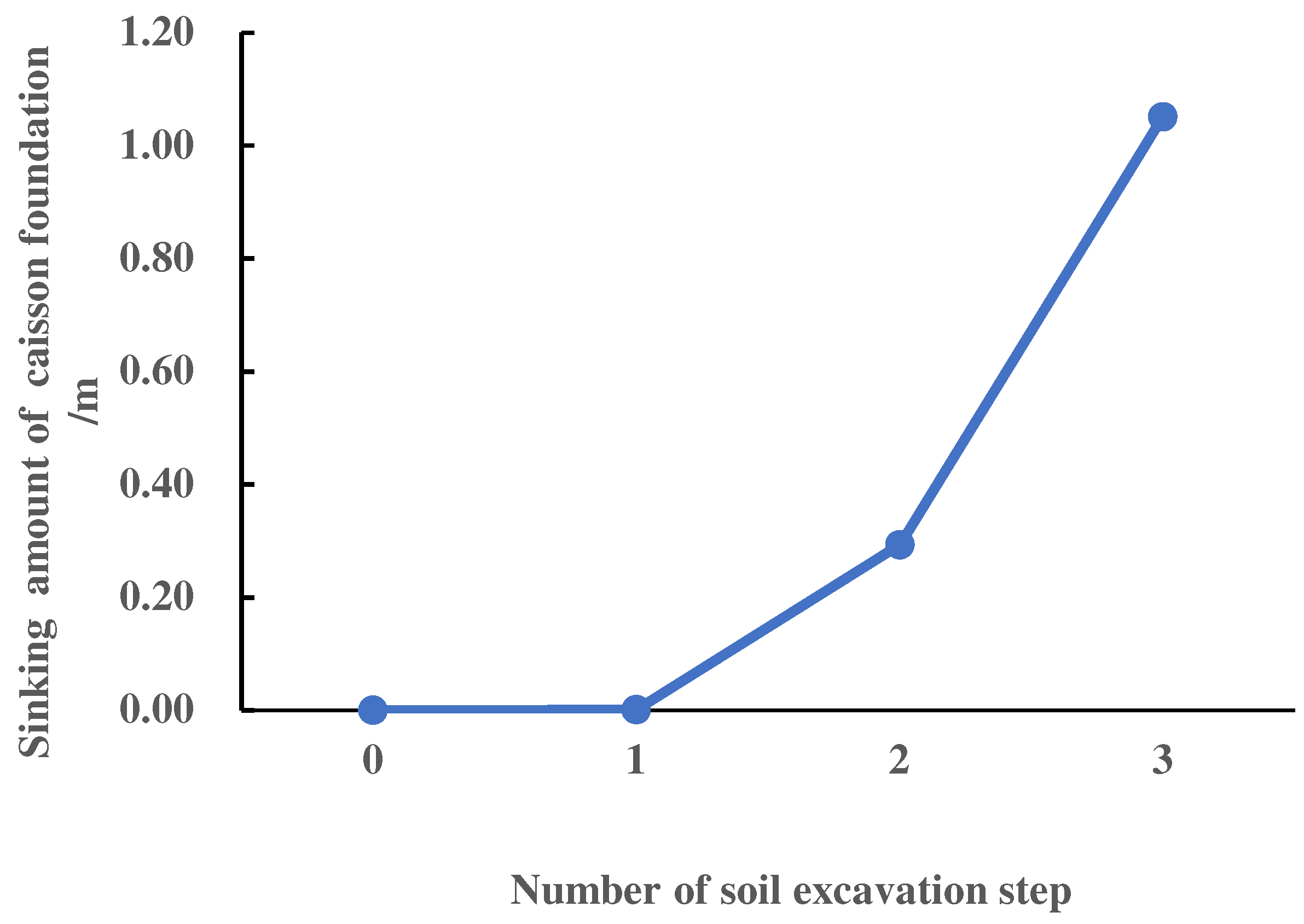
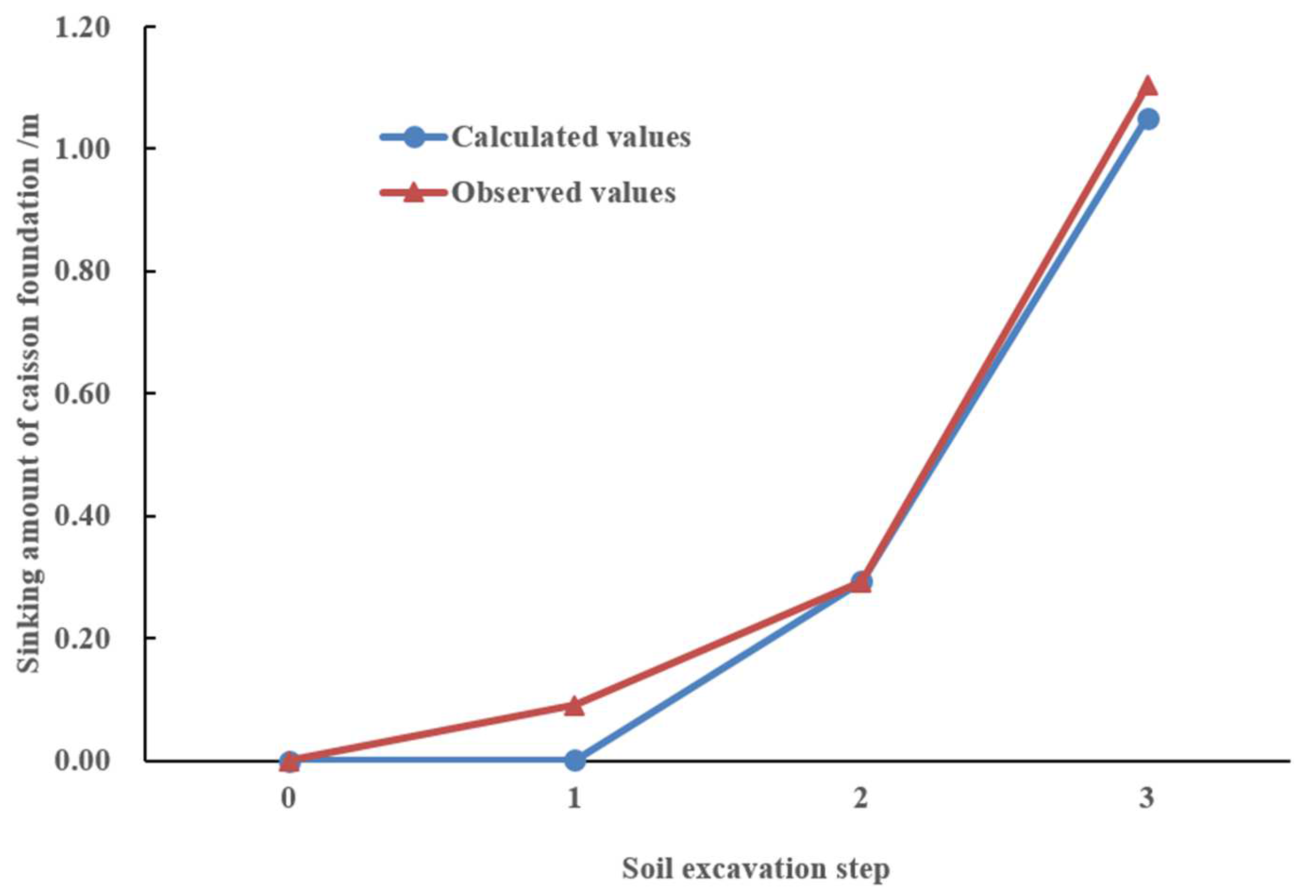
3.2.1. Sinking Amount of Caisson Foundation by Soil Excavation

Figure 11 showed the sinking amount of caisson foundation corresponding to each step of soil excavation. It can be seen that the subsidence was small, only 0.14 cm after 1.35 m deep soil was excavated from 18 inner compartment of caisson foundation (step 1). For step 2, the total sinking amount was 29.3 cm after 1.85 m deep soil was excavated from the inner compartment and the blind area of the inner partition walls (Figure 8c). For the last step of soil excavation, the total sinking amount reached 105.1 cm after 2.85 m deep soil was excavated within 2.0 m width in the outer compartment attached to the inner bulkhead (Figure 8d). From Figure 11, the caisson foundation appears obvious sinking after soil excavation from the inner compartment to outer compartment.

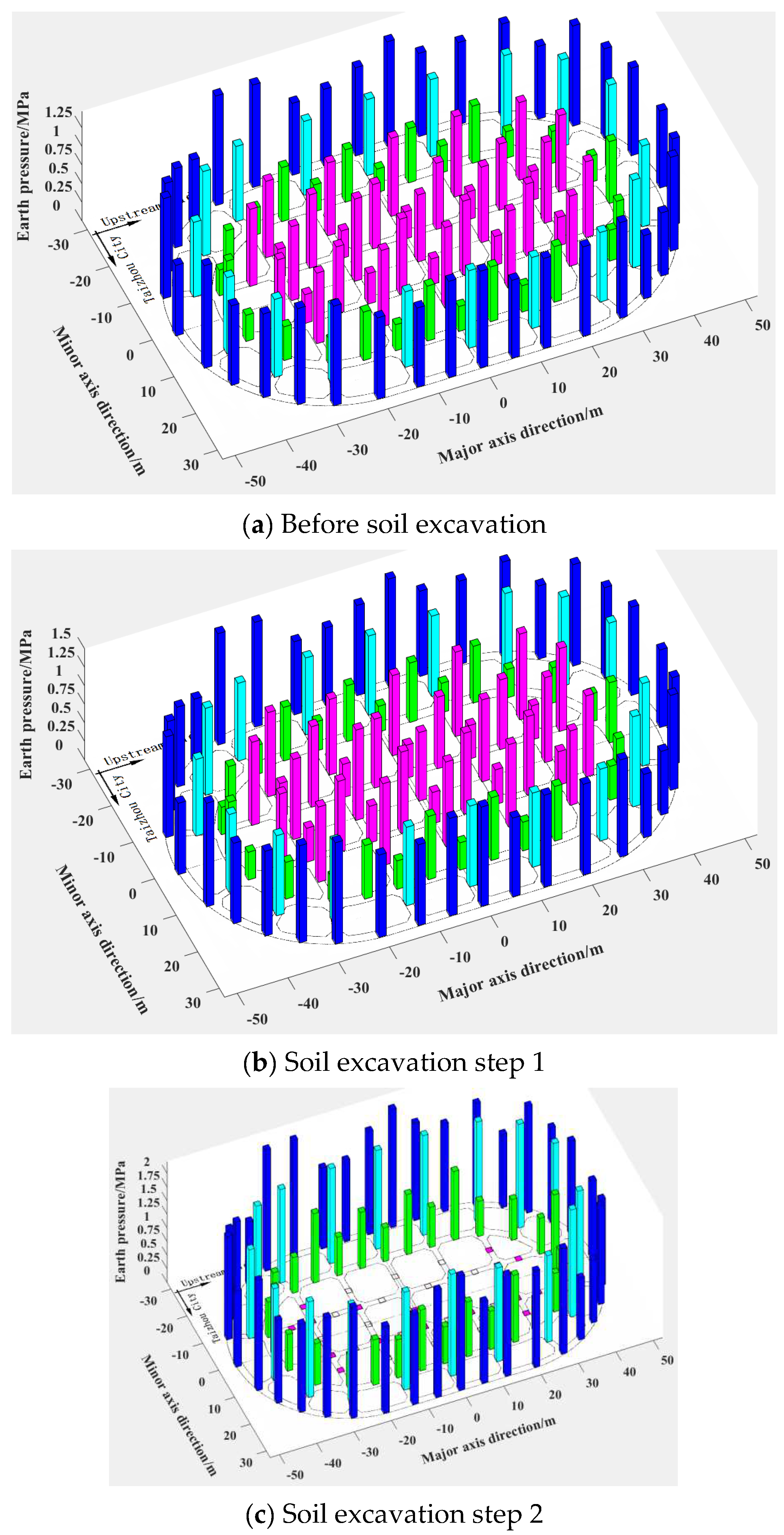
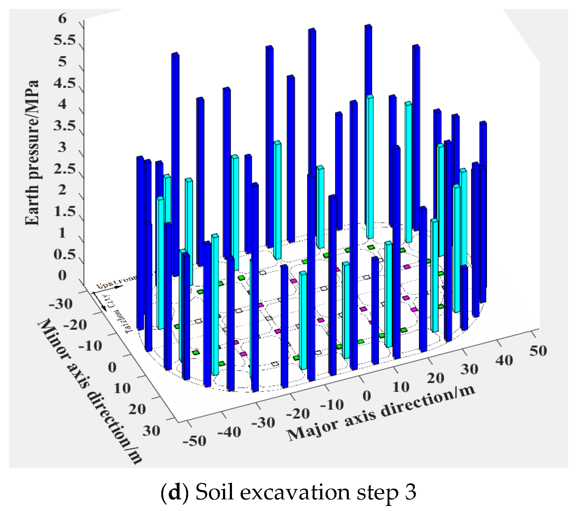
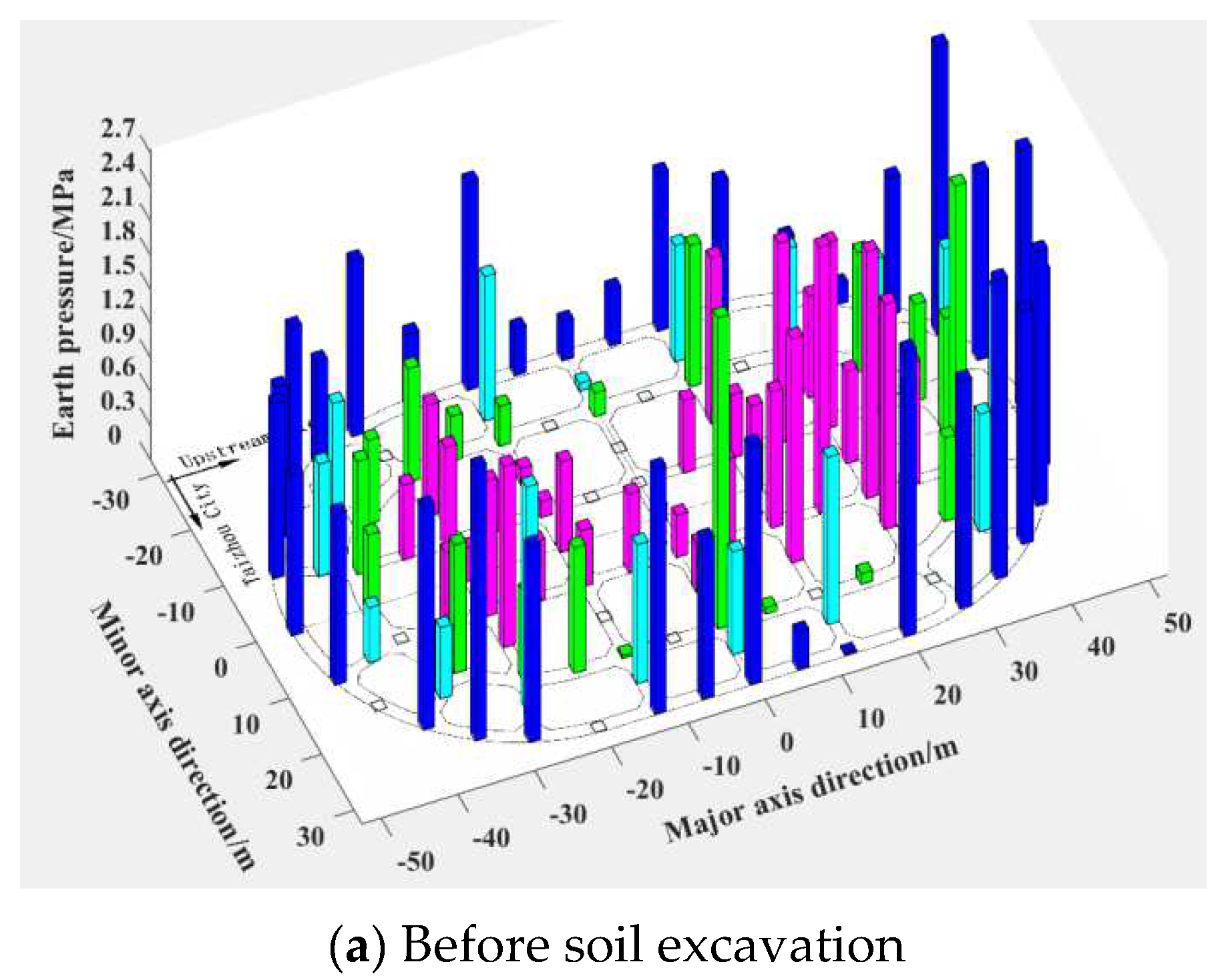
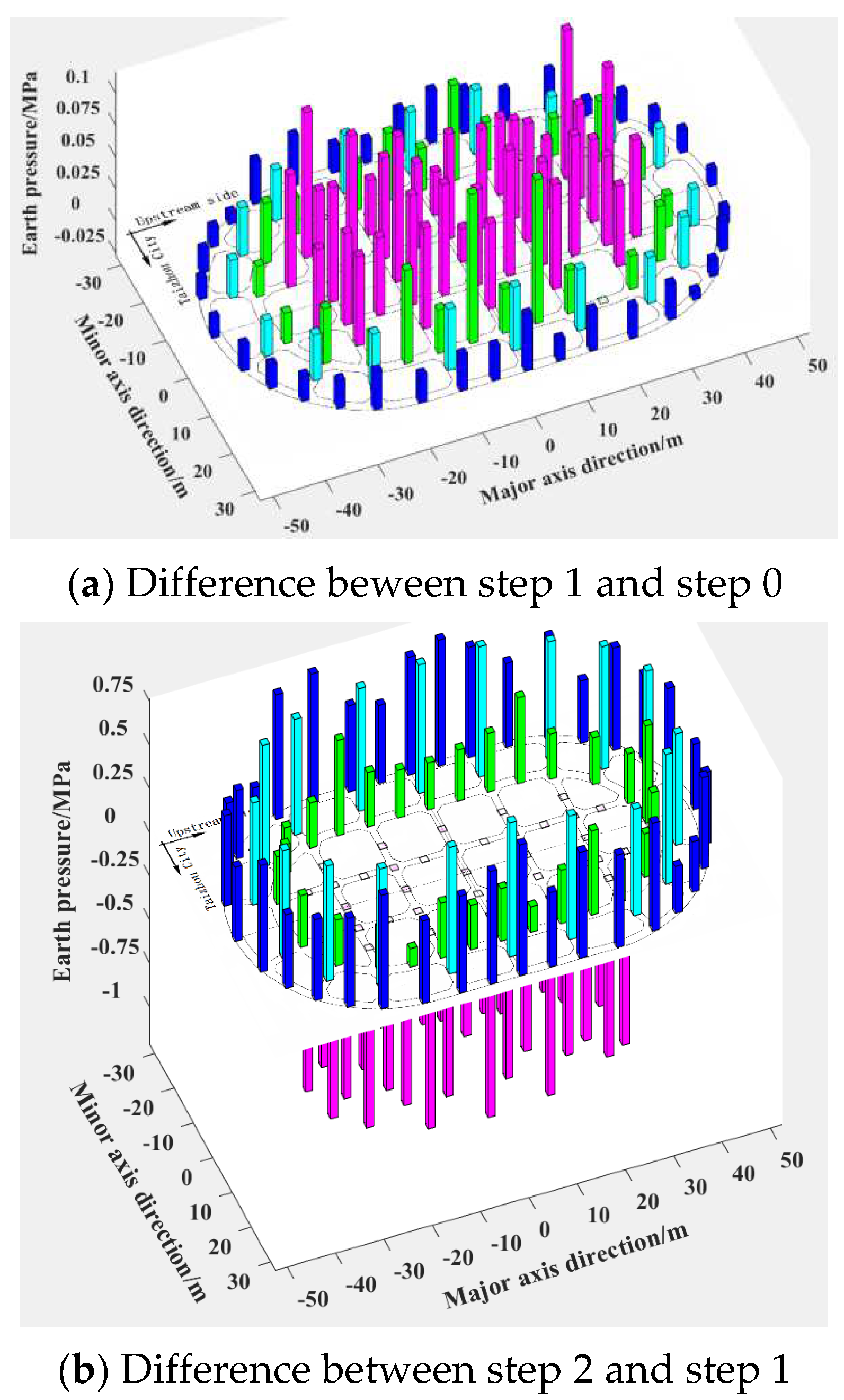
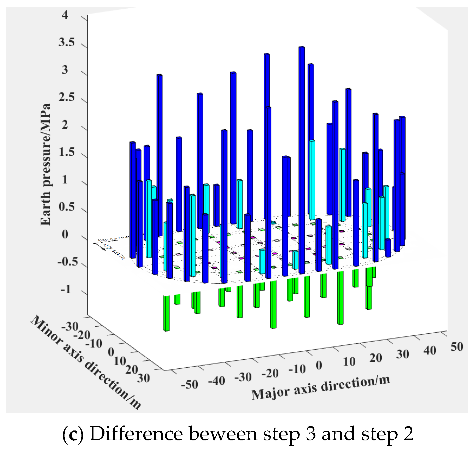
3.2.2. Distribution Characteristics of Earth Pressure

The distribution of earth pressure at the foot blade during the soil excavation process can be obtained by numerical analysis. Based on actual monitoring points, the earth pressure at corresponding position was extracted from numerical analysis one by one so as to facilitate the distribution of earth pressure, which is shown in Figure 12. The earth pressure located different area was displayed in different color, the outer bulkhead area is blue, the outer partition area is turquoise, the inner bulkhead area is green, and the inner partition wall area is magenta. In order to better reveal the variation of earth pressure at the foot blade with soil excavation procedure, the difference value of earth pressure at the foot blade between adjacent soil excavation steps was shown in Figure 13.
From Figure 12 and Figure 13, the distribution characteristics of earth pressure at the foot blade are closely related to the shape and distribution area of the foot blade. Before soil excavation, the maximum of the earth pressure at the foot blade is about 1.25 MPa, occurred in the outer bulkhead. Meanwhile, the earth pressure in the inner bulkhead area was the smallest, which is in the range of 0.25 MPa to 0.75 MPa. After the first step of soil excavation, the earth pressure in the other three areas except inner partition area increased basically within 0.1 MPa because of soil excavation in the inner compartment. After the second step of soil excavation, the earth pressure under the foot blade in the inner partition was less than 0.05 MPa, which is basically hollow, and the earth pressure in the other three areas was significantly increased, especially in the outer partition wall and outer bulkhead. For the last step of soil excavation, the earth pressure of outer partition and outer bulkhead was further increased, and the earth pressure in the outer bulkhead increased greater than that in the outer partition area.
From the above characteristics of earth pressure with soil excavation process, it can be seen that as the soil is excavated from the inner compartment to the blind area under the foot blade and gradually extended to the outer compartment, the earth pressure in the inner compartment gradually decreased to 0 due to the soil excavated from the blind area, while the earth pressure in the outer partition wall and outer bulkhead gradually increased to the maximum strength of the soil. Therefore, with the soil excavation from step 1 to step 3, the earth pressure at the foot blade is gradually transferred from the inner compartment to the outer compartment.

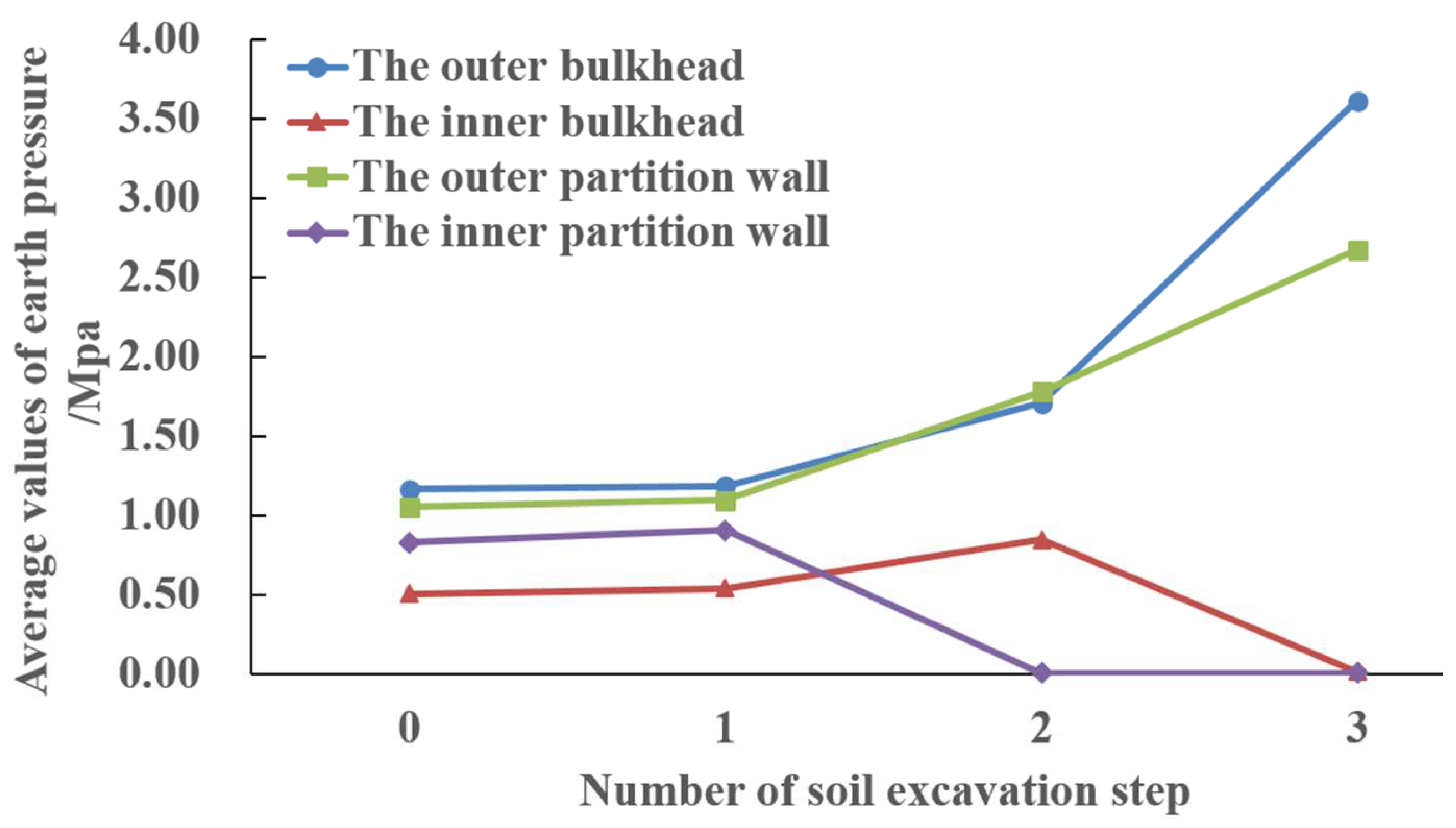
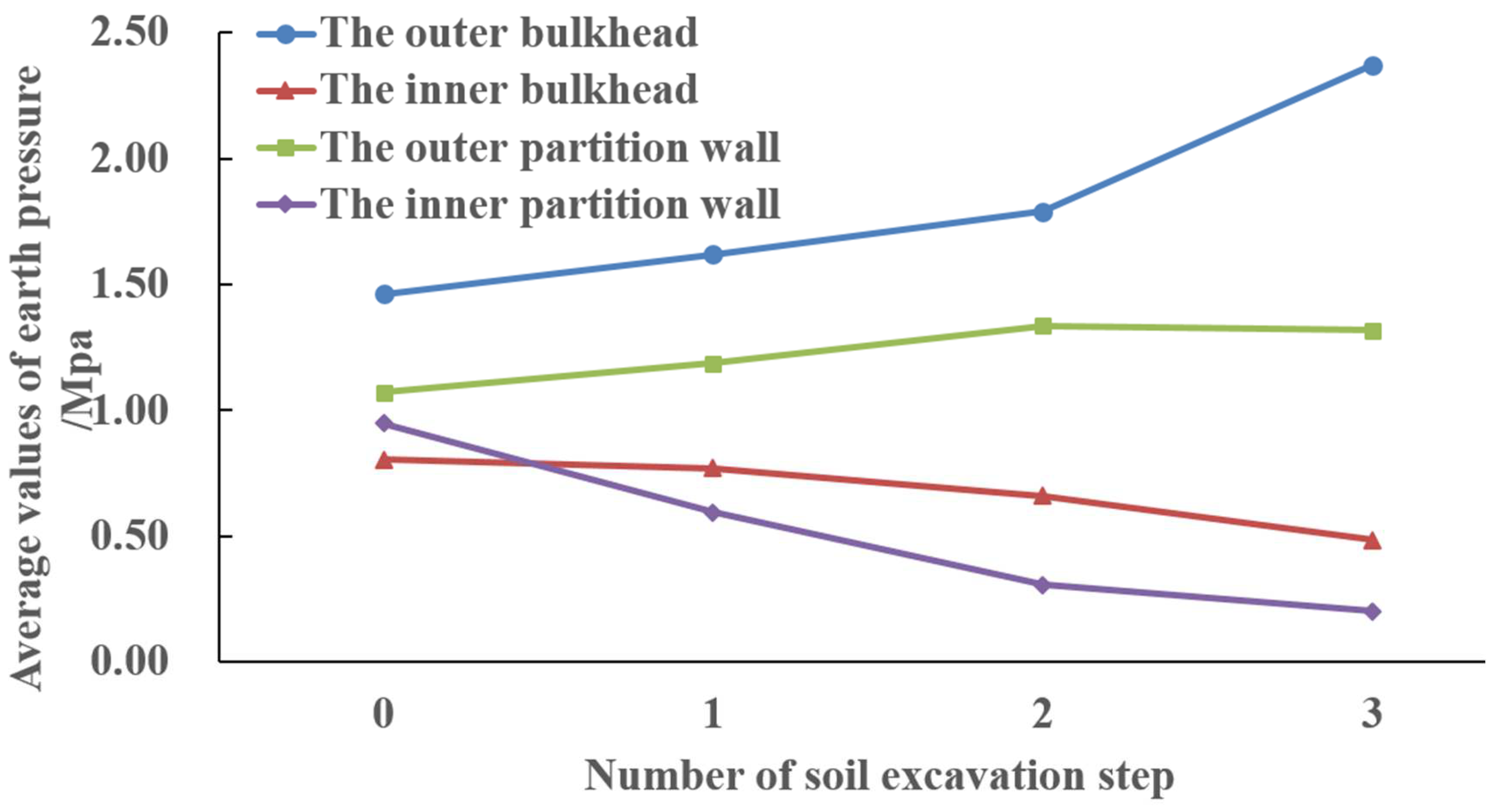
3.2.3. Average Earth Pressure in Different Area

The average of earth pressure can intuitively reflect the transfer characteristics of earth pressure during soil excavation process in four typical areas of the caisson foundation (outer bulkhead, outer partition wall, inner bulkhead, and inner partition wall area). Figure 14 shows the variation of average earth pressure at the foot blade by numerical analysis with soil excavation process. From Figure 14, before soil excavation, the average value in the outer bulkhead area was the largest, which is 1.164 MPa, and it is 1.053 MPa in the outer partition wall area. The average values of the inner bulkhead and inner partition area were 0.827 MPa and 0.501 MPa, respectively. The distribution of earth pressure was characterized by big in the outer areas and small in the inner areas at the bottom of caisson foundation. After soil excavation from step1 to step 3, the average value of earth pressure in the outer bulkhead area was the biggest which is 3.612 MPa, it is 2.673 MPa in the outer partition area, and it was close to 0 in the inner bulkhead and inner partition area.
Because the force balance of caisson foundation is basically maintained during smooth sinking by soil excavation, the soil pressure under the foot blade in the soil excavation area decreased, while the soil pressure in the surrounding area correspondingly increased. With gradual development of soil excavation from the inner compartment to outer compartment, the earth pressure gradually transferred from the inner areas to outer areas of caisson foundation, and the earth pressure in the outer bulkhead and outer partition wall area became bigger and bigger, until the soil reached failure state in the outer bulkhead area, which caused apparent sinking of caisson foundation.

4. Analysis of Monitoring Data

4.1. The Sinking Amount with Soil Excavation Procedure

The caisson foundation of main tower of Changtai Yangtze River Bridge was equipped with systematic monitoring equipment. During the soil excavation process, the sinking amount of caisson foundation was monitored in real time. Figure 15 showed the measured subsidence of caisson foundation corresponding to each step of soil excavation, and the numerical analysis results are also given for comparison.
From Figure 15, the numerical analysis results are in good agreement with actual sinking amount of caisson foundation corresponding to soil excavation procedure. After soil excavation step 1, the measured subsidence of caisson foundation was 9.1 cm, which is bigger than 0.14 cm by numerical result. For step 2, the total sinking amount was 29 cm, which is almost the same with that by numerical result, and for the last step of soil excavation, the actual monitored subsidence was 110.4 cm, while the sinking amount obtained by numerical calculation is 105.1 cm, indicating that the caisson foundation appeared obvious subsidence.

4.2. Distribution Characteristics of Earth Pressure at the Foot Blade

More than 90% of total 119 earth pressure sensors worked well during the first soil excavation stage, which were arranged at the foot blade of caisson foundation. After removing abnormal field data, a three-dimensional histogram curve of earth pressure was drawn based on field data during soil excavation, which is shown in Figure 16. Different area was represented by different colors, which is the same with that in Figure 12. Figure 17 demonstrated the variation curve of the average soil pressure with soil excavation procedure. From Figure 17, before soil excavation, the average earth pressure in the outer bulkhead area was 1.512 MPa which is the biggest, it is about 1.0 MPa in the partition wall areas, and the average value of earth pressure in the inner bulkhead area was about 0.829 which is the smallest.
After soil excavation step 1, the earth pressure of the outer bulkhead and the outer partition wall area slightly increased by 0.202 MPa and 0.143 MPa, respectively. The earth pressure of inner bulkhead remained basically unchanged, and the earth pressure of the inner partition area decreased by 0.388 MPa. For soil excavation step 2, the earth pressure of the outer bulkhead and the outer partition wall area increased continually, and the earth pressure of the inner bulkhead and inner partition wall area slightly decreased, which is caused by soil excavation from the inner compartment. After soil excavation step 3, the earth pressure of outer bulkhead significantly increased to 2.359 MPa, while the earth pressure of the inner partition area decreased to 0.273 MPa because of soil excavation in this area, and the earth pressure of outer partition wall and outer bulkhead area are, respectively, 1.081 MPa and 0.502 MPa.
From the distribution characteristics of earth pressure during soil excavation procedure, it can be seen that the earth pressure of the inner bulkhead and inner partition wall area gradually decreased with soil excavation in the inner compartment, while the earth pressure of outer partition wall and outer bulkhead area continually increased. The earth pressure of the inner areas (inner partition wall and inner bulkhead) gradually transferred to outer areas (outer partition wall and outer bulkhead) with soil excavation from the inner compartment to outer compartment. When the soil was excavated from outer compartment, the earth pressure in outer partition area was evidently decreased and the end resistance was further transferred to outer bulkhead area.

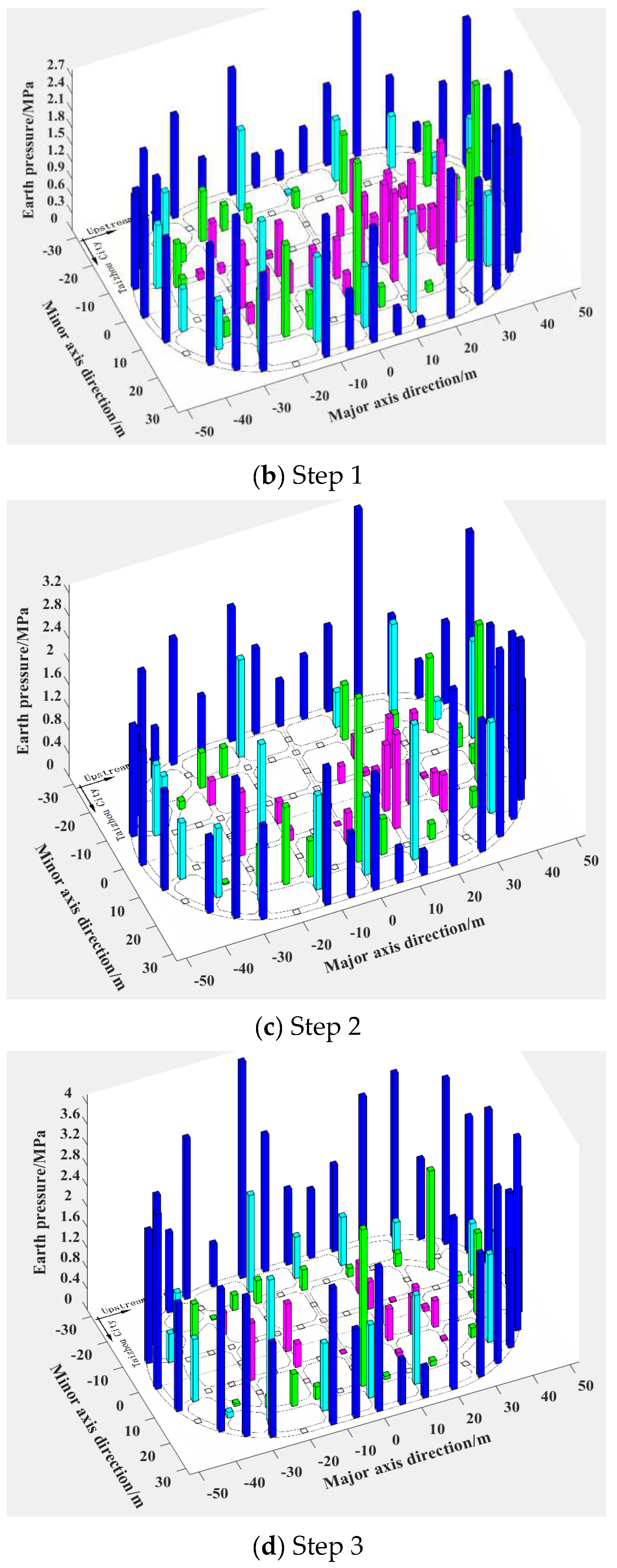
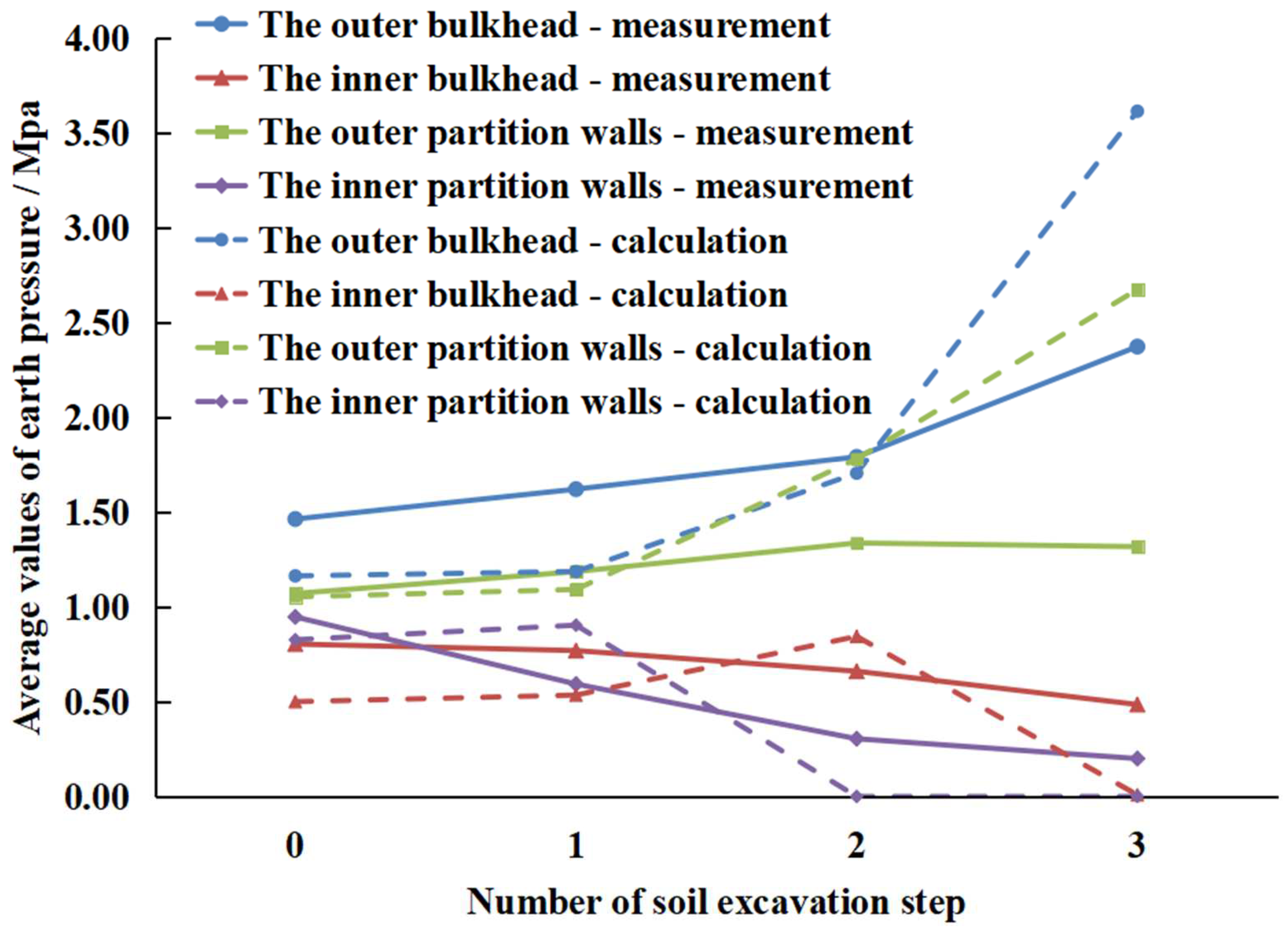
4.3. The Average Earth Pressure with Each Step of Soil Excavation

In order to better reveal the transfer characteristics of the earth pressure among different areas of caisson foundation with the soil excavation process, the average value of measured earth pressures with soil excavation process were shown in Table 3 and Figure 18.
Before soil excavation, the average earth pressure of the outer bulkhead area is 1.46 MPa which is the biggest, it is about 1.07 MPa in the outer partition wall area, and the earth pressure of inner partition wall and inner bulkhead area was 0.95 MPa and 0.81 MPa respectively. After the first stage of soil excavation, the earth pressure of outer bulkhead increased from 1.46 MPa to 2.37 MPa, while the earth pressure of the inner partition wall area gradually deceased from 0.95 MPa to 0.20 MPa, and the earth pressure in the inner bulkhead area was also decreased from 0.81 MPa to 0.49 MPa. For the earth pressure in the outer partition area, it slightly increased from 1.07 MPa to 1.32 MPa. Due to the limitation of soil excavation equipment and field working condition, it was difficult to completely excavate all the soil in the blind area, so there was still some soil in the blind area of the inner partition wall and inner bulkhead to share part of the gravity of the caisson foundation.
In general, the variation of measured earth pressure is consistent with that of earth pressure by numerical results during soil excavation procedure. The average of earth pressure was gradually transferred from the inner compartment to outer bulkhead area with the process of soil excavation. Based on variation characteristics of earth pressure at the foot blade, it can be reasonably judged which part of foot blade is hollow and in which part of the foot blade the effect of soil excavation is not ideal, which can help control the overall sinking state of caisson foundation and provide guidance to soil excavation scheme at later stage of soil excavation construction.

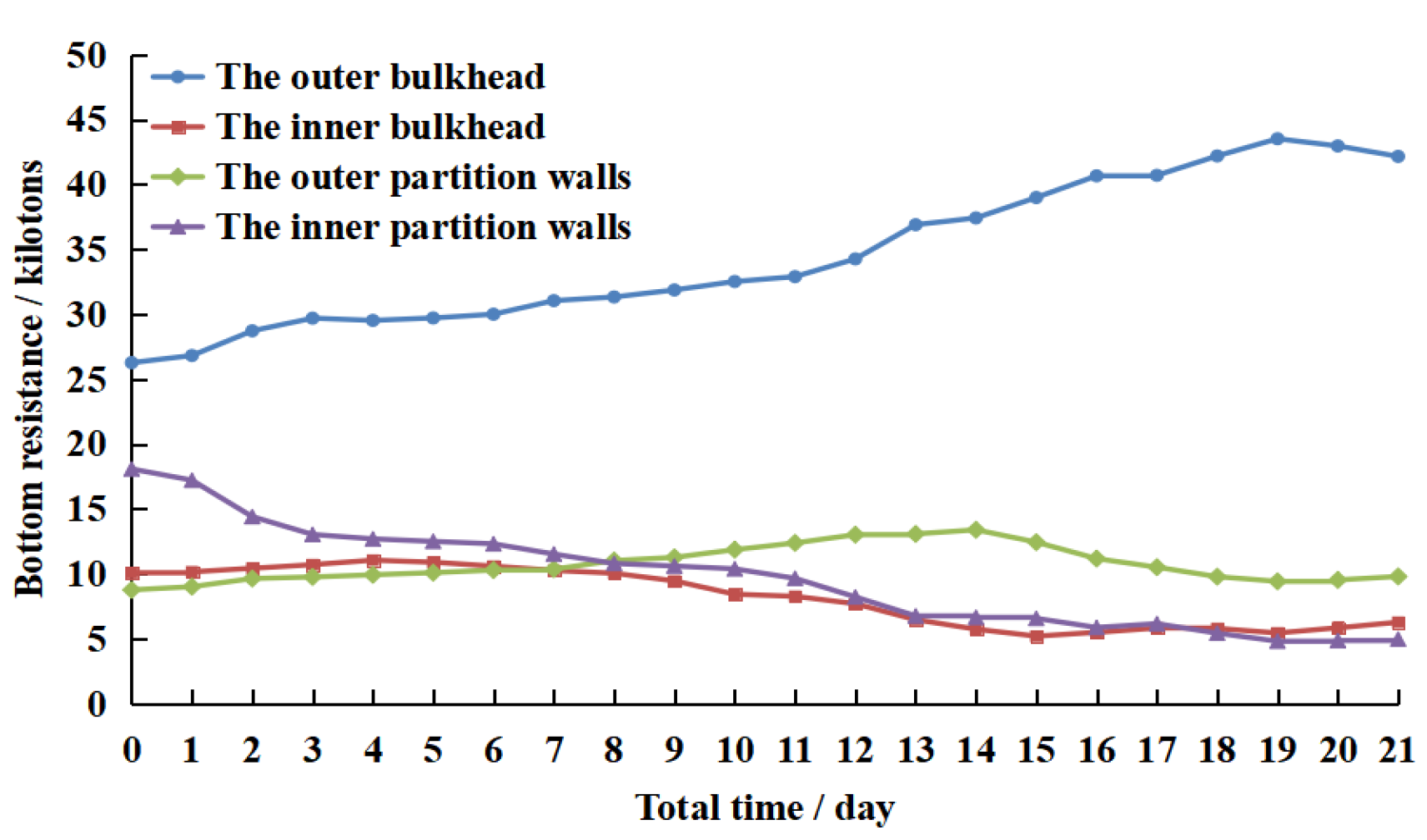
4.4. Distribution Characteristics of End Resistance of Caisson Foundation

If the sinking process of the caisson foundation is smooth during soil excavation, it can be considered as equilibrium condition under the actions of gravity, buoyancy, bottom resistance, and side friction resistance. At the first sinking stage, the side friction resistance is almost close to 0, and the force equilibrium condition of the caisson foundation can be expressed in Equation (1). From Equation (1), the total end resistance can be obtained under the condition of not considering the side friction resistance.
G N w = R b + R f
where, G is the gravity of caisson foundation, N w is the buoyancy, R f is the side friction resistance, and R b is the end resistance.
For the distribution of the end resistance R b in different area of the caisson foundation, it can be calculated as Equation (2) if the earth pressure at the foot blade was known.
R b = i = 1 n ( p i u A i t + λ i p i u A i b )
where, n is the total number of zones of caisson foundation, p i u is the earth pressure on the tread, A i t is the tread area of the foot blade, A i b is the projected area of the incline of the foot blade, and λ i is the scale factor of earth pressure between the incline and the tread of the foot blade. Here, the scale factor can be considered as the constant variable, therefore, by combining Equations (1) and (2), the distribution of end resistance of the caisson foundation can be obtained.
After the first stage of soil excavation, the elevation of the foot blade in the outer bulkhead area was −32.95 m, and the foot blade was buried into the soil by 2.95 m, hence, the side friction resistance can be ignored during the first stage of soil excavation. The end resistance can be calculated using the total weight and buoyancy of caisson foundation, and then, the end resistance in each area of caisson foundation can be also obtained based on the earth pressure and shape of the foot blade (Equation (2)). Figure 19 showed the variation and distribution of end resistance in each area during soil excavation procedure.
From Figure 19, with respect to outer bulkhead, outer partition wall, inner bulkhead and inner partition wall area of the caisson foundation, the end resistances were respectively 26.3 thousand tons, 8.8 thousand tons, 10.1 thousand tons and 18.1 thousand tons before soil excavation. After soil excavation in the inner compartment (step 1), the end resistance of the inner partition wall decreased by 6.6 thousand tons, it slightly increased in the outer partition wall and inner bulkhead area, while it increased by 4.78 thousand tons in the outer bulkhead area. Then, after soil excavation step 2, the end resistance of the inner partition wall decreased by 3.31 thousand tons, it decreased by 2.57 thousand tons in the inner bulkhead area. Due to the total end resistance keeps constant, the reduced end resistance in the inner areas has transferred to outer areas. In the outer partition wall and outer bulkhead, it gradually increased by 2.66 thousand tons and 3.22 thousand tons respectively. After soil excavation step3, the end resistance in the outer bulkhead significantly increased to 43.53 thousand tons, it decreased by 3.22 thousand tons in the outer partition area, and it fluctuated around 6.0 thousand tons in the inner bulkhead and inner partition area.
After the first stage of soil excavation(Figure 20), the end resistance in the outer bulkhead is 42.17 thousand tons, and it was 9.8 thousand tons, 6.27 thousand tons and 4.97 thousand tons respectively in the outer partition wall, inner bulkhead, and inner partition area. It can be concluded that the end resistance mainly concentrated on the outer bulkhead area.
According to the time-history curve of end resistance with soil excavation process, the end resistance of inner bulkhead and inner partition wall gradually decreased with soil excavation procedure in the inner compartment, while it gradually increased in the outer areas, and the end resistance was transferred from the inner areas to outer areas. Furthermore, in the process of soil excavation in the outer compartment, it decreased in the outer partition wall. However, it continued to increase in the outer bulkhead, which caused the end resistance mainly focusing on the outer bulkhead area.

5. Conclusions

According to actual soil excavation procedure of the caisson foundation of the main tower of Changtai Yangtze River Bridge, the distribution and variation characteristics of the earth pressure at the foot blade was analyzed by 3-D numerical method and field data. The field measured data basically proved numerical calculating results. Main conclusions can be made as the follows:
(1)
Based on the principle of soil excavation from the inner compartment to outer compartment, the earth pressure at the foot blade was transferred from the inner compartment to outer compartment of the caisson foundation, and the earth pressure in the outer bulkhead became bigger and bigger, until the soil in the outer areas reached failure state, which caused apparent sinking of caisson foundation. After completing the first stage of soil excavation, the soil in the outer area almost undertook the overall weight of the caisson foundation.
(2)
In the sinking process by soil excavation, the variation of the end resistance was the same with that of the earth pressure at the foot blade. It gradually decreased in the inner partition and inner bulkhead area, on the contrary, it gradually increased in the outer partition and bulkhead area, until the end resistance reached the maximum in the outer bulkhead area.
(3)
The variation of earth pressure and end resistance was revealed by numerical analysis and field measured data. For the sinking process of caisson foundation, the numerical analysis can be used to initially make the soil excavation scheme, and then, it can be dynamically adjusted based on field measured data of earth pressure, which ensure the smooth and safe sinking of caisson foundation construction by soil excavation.

Author Contributions

Conceptualization, M.G.; methodology, M.G. and X.D.; software, X.D. and J.L.; validation, M.G.; formal analysis, M.G.; writing—original draft preparation, M.G.; writing—review and editing, X.D.; supervision, M.G.; project administration, M.G. All authors have read and agreed to the published version of the manuscript.

Funding

This research was funded by Research and Application of Key Techniques for Super-long Span Highway-Railway Cable-stayed Bridge Construction under Asymmetrical Load (2019-MS1-011) in the list of Scientific and Technological Key Projects in Transportation Industry 2019.

Institutional Review Board Statement

The study did not involve humans or animals.

Informed Consent Statement

Informed consent was obtained from all subjects involved in the study.

Data Availability Statement

Data is contained within the article.

Conflicts of Interest

The authors declare no conflict of interest.

References

  1. Duan, L.C.; Yin, Q. Design and Construction of Caissons; Tongji University Press: Shanghai, China, 2006. [Google Scholar]
  2. Shi, Z.; Li, S.Y.; Yang, S.L.; Feng, C.B. Study on the characteristics of friction resistance and the mechanism of sudden sinking in the middle and late sinking stages of super large caisson foundation. Chin. J. Geotech. Eng. 2019, 38, 3894–3904. (In Chinese) [Google Scholar]
  3. Chen, X.P.; Qian, P.Y.; Zhang, Z.Y. Study on penetration resistance distribution characteristic of sunk shaft foundation. Chin. J. Geotech. Eng. 2005, 27, 148–152. [Google Scholar]
  4. Luo, C.Y. Settlement Monitoring and Numerical Simulation Analysis of Super-Deep and Large Caisson Foundation. Ph.D. Thesis, Southwest Jiaotong University, Chengdu, China, 2019. [Google Scholar]
  5. Huang, D. Study on Stress Characteristics and Surrounding Settlement of Large Caisson during Sinking Process. Ph.D. Thesis, Tianjin University, Tianjin, China, 2018. [Google Scholar]
  6. Li, P. Construction Technology for Deep-Water Huge Open Caisson Foundation. Ph.D. Thesis, Southwest Jiaotong University, Chengdu, China, 2017. [Google Scholar]
  7. Yan, F.Y.; Shi, G. Analysis of limiting soil resistance beneath cutting curb during sinking of open caisson. Rock Soil Mech. 2013, 34 (Suppl. 1), 80–87. [Google Scholar]
  8. Xu, W.; Chen, Z.Q.; Xu, Z.Y. Analysis of ultimate bearing capacity of ring cutting curbs on open caisson foundation bevels. J. Huazhong Univ. Sci. Technol. (Nat. Sci. Ed.) 2013, 41, 27–31+41. [Google Scholar]
  9. Jiang, B.L.; Ma, J.L.; Li, M.H.; Chu, J.L. Experiments on spatial stress of foot blade during caisson sinking in water. Rock Soil Mech. 2019, 40, 1693–1703. [Google Scholar]
  10. Zou, H.X.; Ma, J.L.; Zhang, K.; Luo, C.Y.; Yang, B. Study of sinking resistance of large and deep caisson based on centrifugal model test. Rock Soil Mech. 2019, 40, 3969–3976. [Google Scholar]
  11. Zhu, J.M.; Gong, W.M.; Mu, B.G.; Mi, C.J. Research on stress and settlement of super-large open caisson during first lifts. Rock Soil Mech. 2012, 33, 2055–2060+2066. [Google Scholar]
  12. Zhong, J.H. The In-Suit Test Study on Super-Sized Caisson Force during Sinking. Ph.D. Thesis, Southwest Jiaotong University, Chengdu, China, 2016. [Google Scholar]
  13. Zhang, Z.C.; Deng, Y.L.; Zheng, F.L.; Wang, J.C. Analysis on sudden sinking behaviors of massive open caisson in deep-thick soft clay area. Chin. J. Undergr. Spaceand Eng. 2020, 16, 933–943. [Google Scholar]
  14. Mu, B.G.; Wang, Y.; Zhu, J.M. Analysis of large caisson sinking measured resistance. J. Civ. Archit. Environ. Eng. 2012, 34 (Suppl. 1), 107–115. [Google Scholar]
  15. Qin, S.Q.; Yuan, R.A.; Zheng, Q.G.; Fu, Z.G.; Ma, R.P.; Xu, L.P. Research on structural systems for very long-span rail-cum-road cable-stayed bridge. Bridge Constr. 2020, 50, 1–8. [Google Scholar]
  16. Ma, Y.G.; Liu, Y.F.; Huang, R. Study of mechanism and early warning indexes of abrupt sinking of large open caisson in deep soft clay layers. Bridge Constr. 2019, 49, 33–38. [Google Scholar] [CrossRef]
Figure 1. Main Bridge of Changtai Yangtze River Bridge.
Applsci 11 10488 g001
Figure 2. Structure of caisson foundation (unit:m).
Applsci 11 10488 g002aApplsci 11 10488 g002b
Figure 3. Different area at the bottom of caisson foundation.
Applsci 11 10488 g003
Figure 4. Schematic diagram of underwater slope.
Applsci 11 10488 g004
Figure 5. Layout of soil pressure sensors.
Applsci 11 10488 g005
Figure 6. Installing completion of soil pressure cell.
Applsci 11 10488 g006
Figure 7. Overall soil excavation of caisson foundation.
Applsci 11 10488 g007
Figure 8. Schematic diagram of soil excavation steps at the first stage.
Applsci 11 10488 g008
Figure 9. 3-D Finite element model.
Applsci 11 10488 g009
Figure 10. Finite element mesh model.
Applsci 11 10488 g010
Figure 11. Sinking amount corresponding to the step of soil excavation.
Applsci 11 10488 g011
Figure 12. Distribution of earth pressure with soil excavation step by numerical analysis (the blue for the outer bulkhead area, turquoise for the outer partition area, green for the inner bulkhead area, and magenta for the inner partition wall area).
Applsci 11 10488 g012aApplsci 11 10488 g012b
Figure 13. Distribution of earth pressure difference between adjacent soil excavation steps by numerical analysis (the color is for the same meaning in the Figure 12).
Applsci 11 10488 g013aApplsci 11 10488 g013b
Figure 14. Average earth pressure with soil excavation step by numerical analysis.
Applsci 11 10488 g014
Figure 15. Sinking amount comparison between numerical results and the field measurements.
Applsci 11 10488 g015
Figure 16. Distribution of measured earth pressure with soil excavation step (the color is for the same meaning in the Figure 12).
Applsci 11 10488 g016aApplsci 11 10488 g016b
Figure 17. Variation curves of average measured earth pressure.
Applsci 11 10488 g017
Figure 18. Averages of the field measured soil pressure with soil excavation step.
Applsci 11 10488 g018
Figure 19. Variation curves of end resistance in different area by field data.
Applsci 11 10488 g019
Figure 20. Comparison of earth pressure with soil excavation step.
Applsci 11 10488 g020
Table 1. Stratum and soil parameters.
Serial
Number
StratumTop Altitude/mBottom Altitude/mThickness
/m
Weight
/(kN/m3)
Deformation Modulus
/MPa
Poisson’s
Ratio
Cohesion
/kPa
Internal Friction Angle
/(°)
1Silty clay−18.1−22.74.719.48.40.3528.311.1
2Loose silt−22.7−28.25.520.618.50.275.631.4
3Hard plastic
silty clay
−28.2−31.33.120.04.70.3241.320.9
4Slightly dense silt−31.3−33.21.920.68.10.286.535.4
5Soft plastic
silty clay
−33.2−39.76.519.03.80.3437.918.1
6Medium dense silt−39.7−48.28.520.69.30.265.631.4
7Dense fine sand−48.2−53.95.719.815.90.254.735.2
8Dense medium sand−53.9−56.32.420.015.90.253.936.5
9Silty clay−56.3−64.98.619.010.20.3429.110.5
10Dense fine sand−64.9−69.74.819.831.80.242.035.3
Table 2. soil excavation at the first stage.
StepDescriptionProcess Time/DayTotal Time/Day
1Excavating soil to −31.35 m in inner 18 compartment77
2Excavating soil to −31.85 m in inner 18 compartment and blind area under the inner partition walls512
3Excavating soil to −32.85 m in the outer compartment within 2.0 m to the inner bulkhead921
Table 3. Averages of the field soil pressure during soil excavation procedure.
Step NumberAverage of Soil Pressure/MPa
Outer BulkheadInner BulkheadOuter Partition Inner Partition
01.460.811.070.95
11.620.771.190.59
21.790.661.340.31
32.370.491.320.20
Publisher’s Note: MDPI stays neutral with regard to jurisdictional claims in published maps and institutional affiliations.

