Article

Hydrates for Cold Storage: Formation Characteristics, Stability, and Promoters

1
CNOOC Research Institute Ltd., Beijing 100028, China
2
Key Laboratory of Ocean Energy Utilization and Energy Conservation of Ministry of Education, Dalian University of Technology, Dalian 116024, China
*
Authors to whom correspondence should be addressed.
These authors contributed equally to this work and should be regarded as co-first authors.
Appl. Sci. 2021, 11(21), 10470; https://doi.org/10.3390/app112110470
Submission received: 7 August 2021 / Revised: 28 October 2021 / Accepted: 1 November 2021 / Published: 8 November 2021

Abstract

:
The potential of hydrates formed from R141b (CH3CCl2F), trimethylolethane (TME), and tetra-n-butylammonium bromide/tetra-n-butylammonium chloride (TBAB/TBAC) to be used as working substances for cold storage was investigated to provide a solution for unbalanced energy grids. In this study, the characteristics of hydrate formation, crystal morphology of hydrates, and the stability of hydrate in cyclic formation under 0.1 MPa and at 5 °C were carried out. It found that the ice had a positive effect on the hydrate formation under same conditions. Upon the addition of the ice cube, the induction time of R141b, TME, and TBAB/TBAC hydrates decreased markedly, and significantly high formation rates were obtained. Under magnetic stirring, the rate at which TBAB/TBAC formed hydrates was significantly lower than that when ice was used. In microscopic experiments, it was observed that the TBAB/TBAC mixture formed hydrates with more nucleation sites and compact structures, which may increase the hydrate formation rate. In the multiple cycle formation of TBAB/TBAC hydrates, the induction time gradually decreased with the increasing number of formation cycles and finally stabilized, which indicated the potential of the TBAB/TBAC hydrates for application in cold storage owing to their good durability and short process time for heat absorption and release.

1. Introduction

Energy shortage and environmental pollution are some of the most challenging issues worldwide. Cold storage is an important means of saving energy in industry. Cold storage critically impacts macro-control, rational management, utilization efficiency, pollutant emission control, effective load transmission, and effective energy use in industry. The internal mechanism and macro-distribution of working substances used for cold storage were investigated to impart properties that can be exploited to meet energy demands [1]. Depending on the temperature range, cold-storage technology can be utilized in air-conditioning, preservation of food and pharmaceuticals, industrial processes, peak shaving power stations, air separation plants, supercritical air energy storage systems, and low-temperature refrigerators [2]. China has been facing an unbalanced electricity market, with a large peak–valley load gap. The proportion of electricity consumed for air-conditioning exceeds 15%, being the main factor affecting these peak–valley charge differences [3]. Especially in summer, air conditioning electricity consumption accounts for 25–30% of the total electricity demand, where this demand reaches a maximum during the daytime peak, placing severe pressure on the power plants [4]. To effectively minimize the peak–valley power differences in an unbalanced grid supply, methods such as power peak shaving at the supply or user side can be adopted [3,4,5].
Air-conditioning and cold-storage technologies are important means of peak shaving on the user side, where the sensible or latent heat of a material is harnessed to store cold energy by using off-peak electricity and the energy is released when needed [1,6]. At present, common cold-storage methods are divided according to the storage media, which include water, ice, eutectic salts, and hydrates [7,8]. Among these, the first three have numerous shortcomings. For example, the cold-storage density of water is low, and large-area equipment is required. In contrast, the cold storage of ice is significantly denser than water, but has a low cooling efficiency and high energy consumption. Eutectic salts cause equipment corrosion and deterioration. In recent years, hydrates have received much attention as a new clean energy source, and hydrate-based technology is considered as a promising approach to solve energy and environmental problems, e.g., through global warming mitigation by capturing and storing carbon dioxide [9,10], and in heavy metal separation for wastewater treatment [11] and desalination [12]. Hydrates are also considered ideal working substances for cold storage due to the latent heat of gas hydrates being equivalent to that of ice, with a high phase-change temperature of 5–12 °C, high cold-storage density, and small specific volume, thereby overcoming disadvantages such as the low heat storage density, low storage temperature, and susceptibility to aging and failure of water, ice, and eutectic salts, respectively [6,7,8,13,14].
Since the inceptive proposal of gas hydrates as a working substance for cold storage in the early 1980s, scientific and industrial interest worldwide has led to the further development of this concept. The working substance of a cold-storage system directly determines the capacity and efficiency of the system. Therefore, hydrates used as working substances for cold storage should be environmentally friendly, safe, and abundant, and present a high reaction heat, good thermodynamic properties, low subcooling degree, and high growth rate. Freon hydrate has attracted significant attention as a cold-storage working substance because of its properties. The temperature of formation of freon hydrate can be controlled at 5–12 °C, and the cold-storage density of this hydrate is approximately 302.4–464 kJ/kg [15]. However, many freon substances are restricted by the Kyoto Protocol because of their high global warming potential [16]. Therefore, hydrochlorofluorocarbon (HCFC) and hydrofluorocarbon (HFC) refrigerants (such as R134a and R141b), which are alternative working substances, have been extensively investigated [3]. Lee et al. [17] and Hong et al. [18] used stepwise differential scanning calorimetry and different heating methods to determine the operating conditions for R134a. Liang et al. [19] analyzed the crystal structure and crystallization characteristics of R141b gas hydrates and their results confirm that only structure II clathrate hydrate crystal was formed. Because organic refrigerants do not easily dissolve in water, cold-storage processes employing some water-soluble hydrates (such as tetrahydrofuran quaternary ammonium salt) have been studied. Such substances generate hydrates, which can be used to produce hydrate slurries. Suzuki et al. demonstrated that the use of surfactants can reduce the resistance of a trimethylolethane (TME) slurry [20]. Mixed hydrates are solid substances formed by mixing different guest working substances with water in different proportions under certain conditions. They can overcome the shortcomings of using a single working substance for cold storage, which include a long induction period, low conversion efficiency, and low phase transition temperature [21,22,23,24]. TBAC and TBAB are semi-clathrate hydrates. In this structure of hydrates, the guest molecules participate in the lattice structure. Oshima et al. [24] reported that the hydration number of a mixed TBAB/TBAC hydrate was slightly higher than that of the pure hydrate, and the maximum dissociation temperature and enthalpy of the mixed hydrate were higher than those of the pure hydrate. Therefore, mixed hydrates are potentially effective heat storage materials for use under relatively mild conditions.
In this study, the characteristics of hydrate formation from different working substances for cold storage, including the HCFC refrigerant (R141b), water-soluble organic matter (TME), and a TBAB/TBAC mixture, were investigated in order to screen for suitable hydrate storage guest working substances. These substances have a large phase-change heat and high formation rate and can be formed under normal pressure, and are considered to be more desirable cold-working substances. In addition, the analyses considered the practicality of hydrate cold-storage technology, for which rapid and uniform hydrate formation was crucial. Therefore, the influence of common and easy-to-use promoters, such as adding ice, stirring, and the use of nanomaterials, on the rate of hydrate formation was explored to increase the efficiency of hydrates as a working substance for cold-storage technology.

2. Materials and Methods

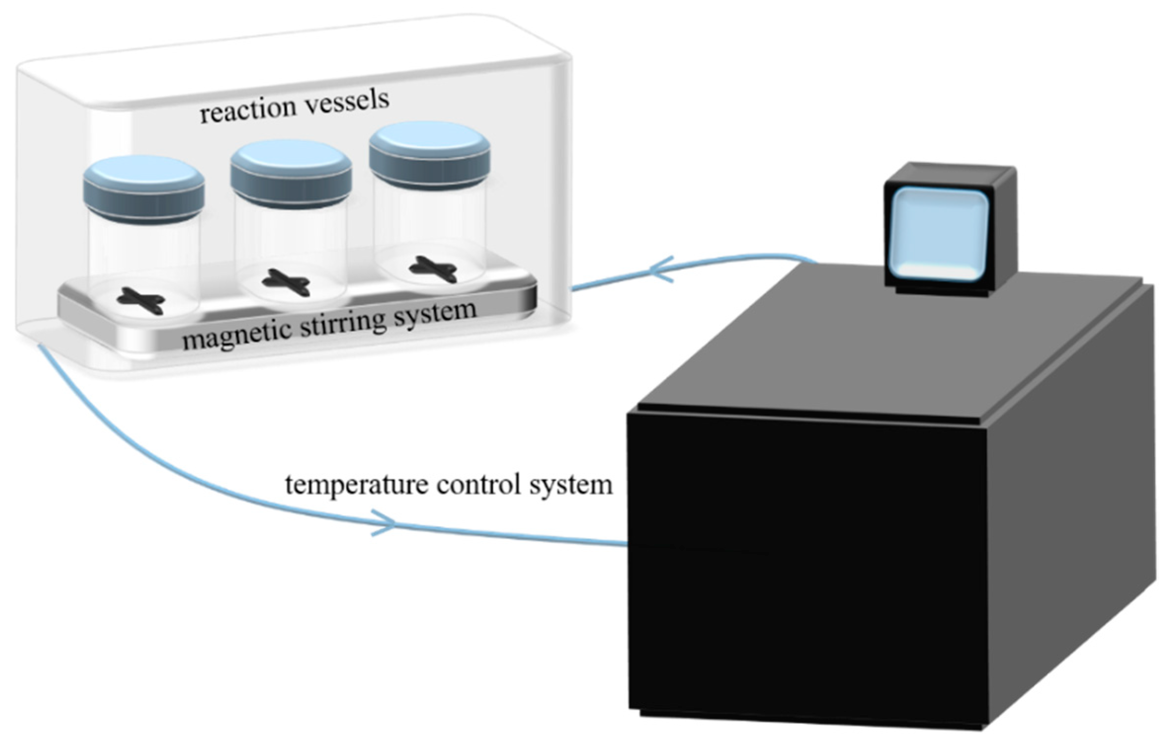
2.1. Experimental Apparatus

The experimental device used to produce the hydrates is shown in Figure 1. It consists of a reaction vessel (100 mL, 0.1 MPa pressure resistance), a magnetic stirring system (WIGGENS WHMIX Drive 6, Magic Motion, Straubenhardt, Germany), and a constant-temperature water-bath (Julabo, FP51, Temperature Control Company, Seelbach, Germany); the device was operated at 0–1200 rpm and −30 to 100 °C, with a temperature control accuracy of 0.01 °C. Microscopic observation of the crystal structures was performed using a high-resolution polarized light microscope (Axio Scope A1 pol, Carl Zeiss Co., Ltd., Gottingen, Germany). A heating and freezing microscope stage (THMS600, Linkam Scientific Co., Ltd., Tadworth, UK) was used to control the temperature from −196 to 600 °C. The maximum heating/cooling rate was 150 °C/min, with an accuracy of 0.01 °C. The samples were weighed using a high-precision electronic balance (ME204, Mettler Toledo Co., Ltd., Zurich, Switzerland), with an accuracy of 0.0001 g.

2.2. Materials

Ultrapure water with resistivity of 18.2 MΩ cm was prepared using an Aquaplore 2S system (Aquapro International Co., LLC, Kent County, DE, USA). The R141b refrigerant (1,1-dichloro-1-fluoroethane, CH3CCl2F) and HCFC-type cold-storage working substances (≥99.9%) were purchased from Zhongxing Refrigeration Technology Co., Ltd. (Quzhou, China) Trimethylolethane (TME, C5H12O3), tetra-n-butylammonium bromide (TBAB, C16H36NBr), and tetra-n-butylammonium chloride (TBAC, C16H36NCl), which are water-soluble organic substances, were purchased from Shanghai Macklin Biochemical Co., Ltd. (Shanghai, China), with purities of ≥97, ≥99.0, and 99.5%, respectively. Graphene with a purity of ≥98 wt%, a lamella diameter of 0.2–10 μm and a specific surface of 100–500 m2/g was purchased from Suzhou Tanfeng Graphene Technology Co., Ltd. (Suzhou, China). The properties of the selected guest molecules are listed in Table 1.

2.3. Methods and Procedures

For production of R141b hydrate, the system to which pure water and ice cube were added were investigated. The R141b mixed solution with a concentration of 27.65 wt% was prepared according to the saturated hydration number (water: R141b = 17:1), that is, a guest solution equal to the saturated hydration number, ignoring the volume change after the solution was mixed. Subsequently, 60 mL of the mixed solution was added to each reaction vessel. The TME hydrate was produced used a similar system. However, an excessive amount of solute was consumed when preparing the solution according to the saturated hydration number; in the experiment water was excessive and the final concentration of TME aqueous solution was 36.36 wt%. Subsequently, 32 mL of the solution was added to each reaction vessel. The cycle stability of TBAB/TBAC was evaluated using pure water and promoting methods (ice cube, stirring, and stirring + graphene). The TBAB and TBAC-mixed aqueous solutions were prepared at an equimolar ratio by mixing pure TBAB and TBAC aqueous solutions (40.00 and 36.50 wt%, 20 and 20 mL, respectively) and there was minor excess of TBAB/TBAC solute, ignoring the volume change after the solute was dissolved in water and the volume change after the solutions were mixed. After the two solutions were mixed, 40 mL of the solution was added to each reaction vessel. The specific experimental working conditions are shown in Table 2. After the solution was prepared, the reaction vessel was placed in a 5 °C water-bath. For the stirred system, a magnetic stirrer was used at 500 rpm. In all the experiments, the formation of the hydrates was observed under 0.1 MPa. When the state of hydrate formation no longer changed, the reaction vessel was removed, the sample was dissociated at ambient temperature (about 25 °C), and the induction and dissociation times were recorded.
At the end of the hydrate cycle formation stability experiment, the hydrate crystals of the systems with added ice cubes were transferred to the heating and freezing microscope stage. The temperature was increased to 25 °C at 20 °C/min until the hydrates were completely dissociated, after which the temperature was lowered to 5 °C at 20 °C/min to reform the hydrates. The crystallization process and the final crystal morphology were observed.

3. Results and Discussion

3.1. Characteristics of Hydrate Formation

Hydrate formation is a crystallization process that includes two consecutive steps: nucleation (formation of crystal nuclei) and formation of crystals through the growth of crystal nuclei [31]. Kvamme et al. defined the induction time as the time to obtain a visible hydrate or to reach the onset of rapid hydrate growth (depending on resolution of the monitoring method) [32]. In this study, the induction time is considered to be the time from the beginning of the experiment to the appearance of the hydrate crystals visible to the naked eyes. The hydrate formation time is considered to be the time from the appearance of visible hydrate crystals to the time when the morphology of hydrate formed in the reaction vessels no longer changed. The data on characteristics of hydrate formation experiments was listed in Table 3, and the comparison of three guest molecules before and after hydrate formation was shown in Figure 2.
In this study, for the pure water system (without any promotion method), R141b and TBAB/TBAC failed to form hydrates within 48 h, as shown in Figure 2(b1,b5). By contrast, for the TME solution, hydrate crystals were formed at the air–water interface at 3 h, and grew rapidly thereafter. The hydrates were concentrated on the bottom layer of the reaction vessel, and visible remaining water was still present in the upper layer, as shown in Figure 2(b3). The excess of water in the TME solution, rather than the excess of TME solute, may result in less water being consumed for hydrate formation. This may be the reason for the presence of clearly visible remaining water in the system. Subcooling is small in the experiment with R141b, moderate in the experiments with TBAB/TBAC, and strong with TME. This may be one of the reasons why only TME hydrates formed in the pure water system (without any promotion method) within 48 h. And in the previous study, the formation of any hydrate was associated with co-existing phases. The stability of hydrate can be expressed as a complex function of the temperature and concentration (and corresponding chemical potential) of all components in all coexisting phases [33]. For the hydrate nucleation process, a certain amount of free guest molecules must be evenly distributed with the water molecules, and the free energy of the guest and water molecules should be relatively low. Only under these conditions can be the nuclei of the hydrate crystals can stabilize and continue to grow [34,35,36,37]. However, because of its very low solubility in water, R141b cannot diffuse uniformly in water molecules [19]. Accordingly, under the effect of the free energy of the water molecules and the R141b molecules, the formation of hydrates by the nucleate may be hindered. Although the guest molecules in free state were evenly distributed in the water molecules, the Gibbs free energy of the system could reach its maximum value, and the formation of a new phase (crystal nucleus) in the system was severely hindered [31]. Therefore, the process of hydrate formation in the solution with crystal nuclei may be very slow and required a long induction time. In addition, previous studies have also showed that homologous polyols such as pentaerythritol and 2,2-dimethyl-1,3-propanediol cannot form hydrates, which indicates that the hydrophobic methyl groups are crucial for the formation of TME hydrates [27]. This could be one reason why TME can nucleate and grow in a short induction time.
To decrease the induction time of the hydrates, a 1 cm3 ice cube was added to the pure water system. Under the same temperature conditions, ice had a positive effect on the hydrate crystallization. Upon addition of the ice cube, the induction time decreased markedly, and significantly high formation rates were finally obtained. R141b started to form a hydrate slurry within approximately 10 min. The water conversion rate continued to increase, and finally a dense and relatively uniform mass was obtained, as shown in Figure 2(b2). TME also began to form in large quantities at approximately 10 min, but there was still some remaining water at the end, as shown in Figure 2(b4). TBAB/TBAC began to form in large quantities at approximately 5 min, and formed a relatively dense hydrate, as shown in Figure 2(b6). The rate of hydrate formation mainly depended on the energy supply rate (when the hydrate grew to the surface) and the rate of surface heat removal (when the hydrate was formed) [38]. Hydrate formation was faster upon the addition of ice under the same conditions because ice positively affected the crystallization of the hydrates. This may be because ice can better accelerate the initiation of hydrate formation by providing additional nuclei for heterogeneous nucleation [39]. Meanwhile, after the ice melted, the water could retain its structure in the liquid phase, and this structure served as a template for the formation of hydrate nuclei [40]. In addition, melting ice absorbed the large amount of energy generated during the formation of the hydrates, thereby increasing the rate of hydrate formation [40]. Previous studies have reported the same experimental phenomenon. Hwang et al. [40] investigated the crystallization and growth of methane hydrate in static melting ice and showed that nucleation only occurred at the methane–water interface. They concluded that nucleation ultimately affects the rate of hydration formation, and the melting ice on the ice surface provides a framework for the nucleation of hydrates, which increases the formation of hydrates.
The effect of magnetic stirring, and of magnetic stirring combined with the addition of 0.1 g graphene, on hydrate formation by TBAB/TBAC was investigated (Figure 2). Hydrate formation increased only when magnetic stirring was used (500 rpm), but at a significantly lower rate than achieved with the addition of the ice cube. The final result was a hydrate slurry with a light yellow color, as shown in Figure 2(b7). For the combined method, there was a moderate increase in the induction time, whereas the formation rate was significantly increased, and a white hydrate slurry was obtained, as shown in Figure 2(b8). Stirring is commonly used as an auxiliary method for hydrate formation. Stirring promotes the mixing of incompatible gas and liquid, and it rapidly renews the reaction interface, thereby enhancing the transfer of heat and mass. Continuous stirring simultaneously increases material diffusion, accelerates material dissolution in the liquid phase, shortens the induction period, and increases the rate of hydrate formation [41,42]. Golombok et al. [43] suggested that hydrate formation is limited by insufficient gas–liquid mixing. In addition, the induction time mainly depended on the stirring speed. Therefore, although the induction time can be shortened by increasing the stirring speed, this must be controlled because high speeds can greatly inhibit hydrate growth [44]. Furthermore, the stirring process only changes the state of the hydrate at the macro level, as it does not affect the microstructures or inherent characteristics. The use of additives can improve the conditions for hydrate formation, change the liquid distribution on the microscopic scale, reduce the interfacial tension between guest molecules and the liquid, increase the solubility and diffusion coefficient of guest molecules in the liquid phase, and enhance contact between water and the guest molecules, thereby contributing to hydrate nucleation [22,45,46]. When stirring was combined with graphene, the induction time increased moderately, whereas the hydrate formation rate increased significantly. This may be attributed to changes in the characteristics of hydrate formation due to the nanostructure characteristics of graphene, thereby promoting hydrate formation. The nucleation of crystals includes two pathways, heterogeneous nucleation and homogeneous nucleation, but the former more easily forms the hydrate crystal nucleus [31]. Graphene increased the heterogeneity of the hydrate formation system, thereby providing the condition of heterogeneous nucleation. Meanwhile, graphene with abundant functional groups on its surface can be used to reduce surface tension and increase the solubility and diffusion of the guest molecule in the liquid phase, which is conducive to hydrate nucleation [47]. It also provides a large specific surface area for contact between the TBAB/TBAC mixture and water molecules. The increased specific surface area leads to a higher number of surface molecules, and a greater intermolecular force between water and the guest molecules [48]. The stronger surface adsorption increases the concentration of the mixture molecules at the interface, which promotes nucleation and increases the rate of hydrate formation. In addition, graphene with high thermal conductivity can eliminate the heat from the system, which maintains the system at a low temperature and makes the hydrate growth more stable [49].

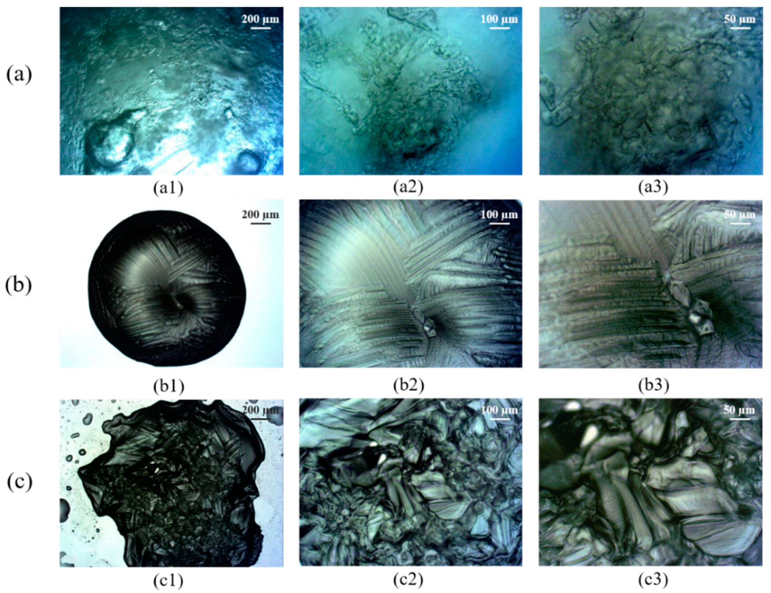
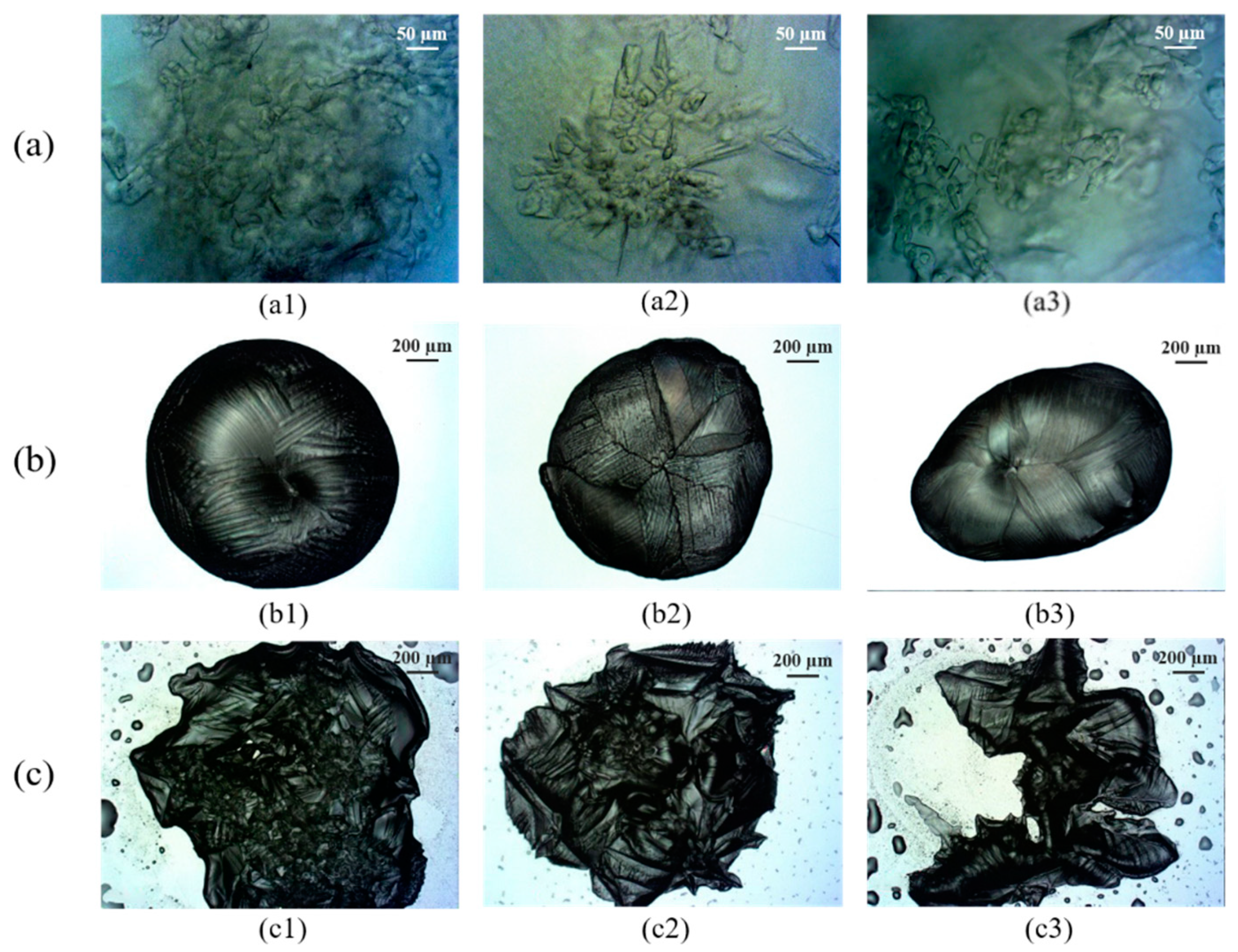
3.2. Crystal Morphology of Hydrates

Information on the characteristics of hydrate formation and the related promoting factors is essential for the effective use of a hydrate as the working substance for cold storage. Microscopic crystallization is of great significance in the identification and analysis of samples and their respective formation mechanisms. Ohmura and his coworkers had conducted comprehensive studies of hydrate crystal morphology in different experiment conditions [50,51,52,53]. They observed the formation and growth of crystal growth of ionic semi-clathrate hydrate formed in CO2 gas + TBAB aqueous solution system, and they found that the hydrate crystals initially grew in the liquid phase, instead of growing at the gas/liquid interface [52,53]. Makogon et al. [54] synthesized the single crystals from THF hydrate in the laboratory, and their microscopic analysis showed that inhibitors can change the growth characteristics of such crystals. Delahaye et al. [55] studied the particle distribution in the hydrate slurry of THF and ice at the microscopic level and concluded that this slurry can be used as a refrigerant. The microscopic evaluation of the morphological characteristics of the hydrate crystals was performed herein to obtain the characteristics of formation of R141b, TME, and TBAB/TBAC hydrates.
As shown in Figure 3a, the R141b hydrate crystals were mainly granular or dendritic, and microporous structures were distributed on the hydrate surface. The overall crystal distribution was uneven with local clusters present. The formation rate increased greatly after the ice cubes were added, possibly because supercooling is conducive to the formation of the hydrate crystals. However, once the crystals were stable, the solution was isolated into small chambers, and the non-diffused R141b clusters and liquid water were separated. The diffusion of R141b molecules was suspended, and there was no further formation of the hydrate crystals [19]. These results shows that the micro-environment for the formation of the R141b hydrate may be affected by two factors that restrict each other, namely diffusion of the molecules and the rate of crystal nucleation.
As shown in Figure 3b, the TME hydrate presented an ellipsoid shape when viewed on the 200 μm scale. At 100 μm resolution, vein-like structures were observed on the surface of the ellipsoid where the vein distribution was uniform with a certain regularity. At 50 μm resolution, crystal grains were observed at the junction of the veins and were exposed to the outer surface (air). In addition, the crystals were pentagonal, hexagonal, and partly irregular. The nucleation and growth rates may determine the hydrate morphology. The nucleation rate increased at higher grain growth rates, and the diminished space may restrict growth of the crystal nucleus, which could be considered the cause of the formation of irregular hydrate crystals. This phenomenon is similar to that reported by other researchers [56]. The single crystal X-ray structure analysis indicated that TME hydrate crystals were lamellar, with alternating TME and water layers [27]. The formed hydrate may constitute a barrier, which easily hindered diffusion of the guest molecules and heat exchange, which in turn decreased crystal growth and increased grain sizes.
As shown in Figure 3c, the crystal grains at the edge of the TBAB/TBAC hydrate were large with an irregular polygon morphology, which is similar to previous studies [52,53]. The hydrate surface was uneven, with small and raised structures distributed throughout. These projecting structures were interconnected in a vein-like shape. Densely distributed crystal grains with uneven heights and a gull-like morphology were present on the surface of the hydrate crystal, and the crystals were very dense. The TBAB/TBAC molecules and water molecules are mutually soluble, which may provide multiple nucleation sites for hydrates formation. Initially, both water and guest molecules were present in sufficient amounts, which was conducive to continuous crystal growth and the formation of larger crystal grains. Meanwhile, multiple crystal grains continued to grow until they were in close contact with each other, after which the outline of the crystal grains at the boundary became linked in vein-like structure, and competitive growth occurred. Other studies have also shown similar results [57,58,59]. Multi-site nucleation may be conducive to the rapid growth of TBAB/TBAC hydrate, and the dense crystal structure could be conducive to the conversion of water into more hydrates.
Repeated experiments with R141b, TME, and TBAB/TBAC hydrates were also con-ducted in this study. The experiments of each hydrate formation were repeated three times, and the crystal morphologies of the sequence of repeated experiments of each hydrate at 5 °C and 0.1 MPa are shown in Figure 4. As shown in Figure 4a, although there are slight differences between Figure 4(a1–a3), the crystal morphology of R141b hydrate was mainly granular or dendritic. Uneven distribution of the entire crystal and the local clusters were present; as shown in Figure 4b, in all cases, the TME hydrate was ellipsoidal, with a vein-like structure observed on the surface of the ellipsoid, and the distribution of granule also had a certain regularity. As shown in Figure 4c, all the TBAB/TBAC hydrates had an uneven surface, where small raised structures were distributed. These protrusions were connected to each other in a vein-like shape. Moreover, uneven high crystal grains with gull-like morphology were distributed on the surface of hydrate crystals with larger edge crystal grains, thereby presenting an irregular shape. Based on the above results, it can be found that the hydrate crystals have similar morphologies in repeated experiments under the same conditions.

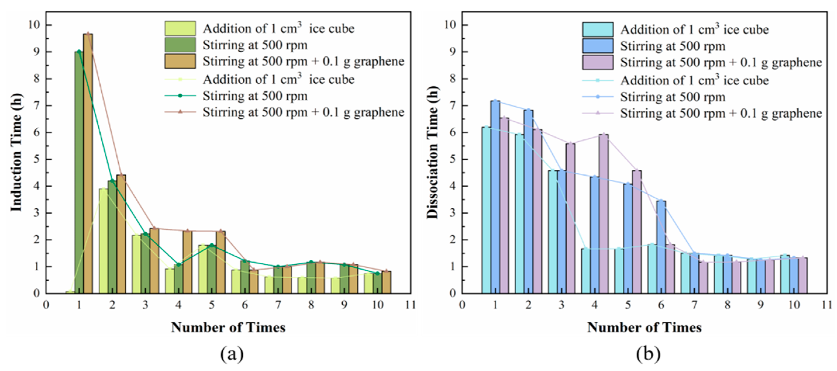
3.3. Stability of TBAB/TBAC Hydrate in Cyclic Formation

The practical use of a mixed-hydrate working substance will facilitate significant future developments in the cold storage industry. At present, there are few studies on this topic, and a suitable mixed-hydrate working substance has not yet been fully developed. The rapid and stable formation of hydrates is of great importance for the application of cold-storage technology. A shorter induction time could decrease the time and energy costs, thereby increasing the efficiency of the cold-storage system. From the previous analysis, the TBAB/TBAC hydrate was found to have a shorter induction time and faster formation rate than the other hydrates.
The formation–dissociation experiments were conducted using different promotion methods such as adding a 1 cm3 ice cube, magnetic stirring at 500 rpm, and combining 500 rpm magnetic stirring with the addition of 0.1 g graphene, each of which ran for 10 cycles. In this study, the hydrate dissociation time was considered to be the time from which the reaction vessel reached ambient temperature to the time when all the hydrate crystals dissociated. The experimental results show that the induction time gradually decreased with increasing numbers of formation cycle, and finally stabilized, as shown in Table 4 and Figure 5. After hydrates were formed at the first cycle, there was more and more water with a memory effect in the following formation cycles, so the induction time had a tendency to decrease. Eventually, almost all of the water in the system had formed hydrate and the induction time tends to be stabilized. In addition, as more water in the system had a memory effect, it may provide more nucleation sites within the system and more dispersed hydrate particles would be formed when the hydrate was formed again. The dispersed particles may have a larger heat exchange area which may reduce the dissociation time in the following dissociation cycle. When the formation process stabilized, the hydrate dissociation process also stabilized. In general, with the use of ice, the formation process and dissociation processes require less time than required with the two other promotion methods. While, in the ice-added system, the induction time in the second formation was longer than that for the first formation step. This may be due to the fact that no more ice was added after the first cycle. After dissociation of the hydrates, no ice provided additional nuclei for heterogeneous nucleation and molten ice was no longer available to provide a template for forming the hydrate nuclei, which led to a longer time for the secondary formation of hydrates. The overall trends for magnetic stirring alone and magnetic stirring combined with 0.1 g graphene were the same. However, the single method was more effective than the combined method for the first five formation–dissociation cycles. Subsequently, the hydrate induction time for the combined method gradually decreased, affording a shorter induction time than that of the single promotion method. The time required for the formation and dissociation of the TBAB/TBAC hydrate after multiple cycles was stabilized at about 0.75 and 1.25 h, respectively, with good long-term stability. Other studies have also shown hydrate slurries with similar properties [60,61]. This indicates that the TBAB/TBAC hydrate shows potential for use as a cold-storage working substance.

4. Conclusions

The formation characteristics, crystal morphology, and factors promoting the formation of hydrate of R141b, TME, and TBAB/TBAC mixtures under 0.1 MPa and 5 °C were investigated. The produced hydrates presented high latent heat and could be formed under normal pressure, which indicated that these hydrates have the potential for use in cold-storage technologies. The main conclusions of this study are as follows:
(1)
The R141b and TBAB/TBAC solutions did not form hydrates within 48 h when no induction or promotion measures were included. By contrast, hydrate crystals were formed from the TME solution after 3 h of reaction.
(2)
When a 1 cm3 ice cube was added to the reactor, the induction time for hydrate formation decreased, and the formation rate increased. When 500 rpm magnetic stirring was used, although the rate of hydrate formation from the TBAB/TBAC mixture was improved, the formation rate was significantly lower than that achieved with the addition of ice. When magnetic stirring at 500 rpm was combined with 0.1 g graphene, the induction time increased slightly. Nevertheless, because of nanostructures’ characteristics and the high thermal conductivity of graphene, it could provide a large specific surface area for the contact between the TBAB/TBAC mixture and water molecules while eliminating the heat from the system, which may promote the formation of hydrates and significantly increases the formation rate.
(3)
Microscopic examination was conducted to obtain the morphological characteristics of the hydrate crystals produced. The R141b hydrate crystals were mainly granular or branched and occurred as local clusters, which were easily separated by free water. The TME hydrate crystals presented an overall ellipsoid shape and a vein-like surface with large crystal grains, which may not be conducive to mass transfer. Many nucleation sites were obtained when TBAB/TBAC hydrates were formed and the crystal structure was dense, which may improve the formation rate.
(4)
The time for the formation of hydrates from the TBAB/TBAC mixture during the formation cycles gradually decreased with the increasing numbers of cycles and finally stabilized. When the formation process stabilized, the hydrate dissociation process also stabilized. This phenomenon could indicate the potential of these hydrates for application in cold storage owing to their good durability and short process time for heat absorption and release.

Author Contributions

Conceptualization, C.L.; data curation, M.W.; funding acquisition, H.C.; methodology, H.C. and M.W.; validation, Z.L. and B.F.; writing—original draft, H.C. and B.H.; writing—review and editing, C.L. and B.H.; investigation, B.H. and C.L. All authors have read and agreed to the published version of the manuscript.

Funding

This research was funded by National Natural Science Foundation of China (Grant No. 51734010).

Conflicts of Interest

The authors declare no conflict of interest.

References

  1. Cheng, C.; Wang, F.; Tian, Y.; Wu, X.; Zheng, J.; Zhang, J.; Li, L.; Yang, P.; Zhao, J. Review and Prospects of Hydrate Cold Storage Technology. Renew. Sustain. Energy Rev. 2020, 117, 109492. [Google Scholar] [CrossRef]
  2. Chen, J.; Xie, Y.; Yang, Y.; Sun, J.; Xu, Z. Alternative Refrigerant Hydrate for Cold Storage Air Conditioners. Build. Energy Effic. 2020, 48, 9–14. [Google Scholar]
  3. Fan, S.; Xie, Y.; Guo, K.; Liang, D.; Gu, J. Advance of Gas Hydrate Cool Storage Technology Used in Air Conditioning System. J. Chem. Ind. Eng. China 2003, 54, 131–135. [Google Scholar]
  4. Fang, G. Cold Storage Air Conditioning Engineering Practical New Technology; Posts & Telecom Press: Beijing, China, 2000. [Google Scholar]
  5. Li, H.; Du, Y.; Bao, Y. A View on Natural Gas Peak-Shaving in China from the Perspective of Power Demand Side Management. Nat. Gas. Ind. 2011, 31, 107–109. [Google Scholar]
  6. Wang, X.; Dennis, M.; Hou, L. Clathrate Hydrate Technology for Cold Storage in Air Conditioning Systems. Renew. Sustain. Energy Rev. 2014, 36, 34–51. [Google Scholar] [CrossRef]
  7. Hasnain, S.M. Review on Sustainable Thermal Energy Storage Technologies, Part II: Cool Thermal Storage. Energy Convers. Manag. 1998, 39, 1139–1153. [Google Scholar] [CrossRef]
  8. Li, G.; Hwang, Y.; Radermacher, R. Review of Cold Storage Materials for Air Conditioning Application. Int. J. Refrig. 2012, 35, 2053–2077. [Google Scholar] [CrossRef]
  9. Zhang, L.; Yang, L.; Wang, J.; Zhao, J.; Dong, H.; Yang, M.; Liu, Y.; Song, Y. Enhanced CH4 Recovery and CO2 Storage Via Thermal Stimulation in The CH4 /CO2 Replacement of Methane Hydrate. Chem. Eng. J. 2017, 308, 40–49. [Google Scholar] [CrossRef]
  10. Sun, L.; Wang, T.; Dong, B.; Li, M.; Yang, L.; Dong, H.; Zhang, L.; Zhao, J.; Song, Y. Pressure Oscillation Controlled CH4/CO2 Replacement in Methane Hydrates: CH4 Recovery, CO2 Storage, and Their Characteristics. Chem. Eng. J. 2021, 425, 129709. [Google Scholar] [CrossRef]
  11. Dong, H.; Zhang, L.; Ling, Z.; Zhao, J.; Song, Y. The Controlling Factors and Ion Exclusion Mechanism of Hydrate-Based Pollutant Removal. ACS Sustain. Chem. Eng. 2019, 7, 7932–7940. [Google Scholar] [CrossRef]
  12. Li, F.; Chen, Z.; Dong, H.; Shi, C.; Wang, B.; Yang, L.; Ling, Z. Promotion Effect of Graphite on Cyclopentane Hydrate Based Desalination. Desalination 2018, 445, 197–203. [Google Scholar] [CrossRef]
  13. Strobel, T.A.; Hester, K.C.; Koh, C.A.; Sum, A.K.; Sloan, E.D. Properties of The Clathrates of Hydrogen and Developments in Their Applicability for Hydrogen Storage. Chem. Phys. Lett. 2009, 478, 97–109. [Google Scholar] [CrossRef]
  14. Wang, X.; Zhang, F.; Lipiński, W. Carbon Dioxide Hydrates for Cold Thermal Energy Storage: A review. Sol. Energy 2020, 211, 11–30. [Google Scholar] [CrossRef]
  15. Ternes, M.P. Studies on the R-12 Gas Hydrate Formation Process for Heat Pump Cool Storage Applications. In Proceedings of the DOE Physical and Chemical Energy Storage Annual Contractors Review Meeting, Arlington, VA, USA, 12–14 September 1983. [Google Scholar]
  16. Wang, K.; Magnus, E.; Hwang, Y.; Radermacher, R. Review of Secondary Loop Refrigeration Systems. Int. J. Refrig. 2010, 33, 212–234. [Google Scholar] [CrossRef]
  17. Lee, D.; Lee, Y.; Choi, W.; Lee, S.; Seo, Y. Accurate Measurement of Phase Equilibria and Dissociation Enthalpies of HFC-134a Hydrates in The Presence of NaCl for Potential Application in Desalination. Korean J. Chem. Eng. 2016, 33, 1425–1430. [Google Scholar] [CrossRef]
  18. Hong, H.J.; Ko, C.H.; Song, M.H.; Lee, S.; Seong, K. Effect of Ultrasonic Waves on Dissociation Kinetics of Tetrafluoroethane (CH2FCF3) Hydrate. J. Ind. Eng. Chem. 2016, 41, 183–189. [Google Scholar] [CrossRef]
  19. Liang, K.; Yuan, Z.; Wang, L.; Tan, Y.; Rui, S.; Dong, B.; Yang, S.; Liu, R. Analysis of Crystal Structure and Crystallization Characteristics of R141b Gas Hydrate. J. Chem. Eng. Chin. Univ. 2017, 31, 1293–1300. [Google Scholar]
  20. Suzuki, H.; Wadab, N.; Komod, Y.; Usui, H.; Ujiie, S. Drag Reduction Characteristics of Trimethylolethane Hydrate Slurries Treated with Surfactants. Int. J. Refrig. 2009, 32, 931–937. [Google Scholar] [CrossRef]
  21. Belandria, V.; Mohammadi, A.H.; Richon, D. Compositional Analysis of the Gas Phase for the CO2 + N2 + Tetra-n-butylammonium Bromide Aqueous Solution Systems under Hydrate Stability Conditions. Chem. Eng. Sci. 2012, 84, 40–47. [Google Scholar] [CrossRef]
  22. Yang, M.; Song, Y.; Liu, W.; Zhao, J.; Ruan, X.; Jiang, L.; Li, Q. Effects of Additive Mixtures (THF/SDS) on Carbon Dioxide Hydrate Formation and Dissociation in Porous Media. Chem. Eng. Sci. 2013, 90, 69–76. [Google Scholar] [CrossRef]
  23. Youssef, Z.; Hanu, L.; Kappels, T.; Delahaye, A.; Fournaison, L.; Zambrana, C.; Pollerberg, C. Experimental Study of Single CO2 and Mixed CO2 + TBAB Hydrate Formation and Dissociation in Oil-in-Water Emulsion. Int. J. Refrig. 2014, 46, 207–218. [Google Scholar] [CrossRef]
  24. Oshima, M.; Kida, M.; Jin, Y.; Nagao, J. Dissociation Behaviour of (Tetra-n-butylammonium bromide +Tetra-nbutylammonium chloride) Mixed Semiclathrate Hydrate Systems. J. Chem. Thermodyn. 2015, 90, 277–281. [Google Scholar] [CrossRef]
  25. Li, J.; Liang, D.; Guo, K.; Wang, R. Experiments on fast nucleation and growth of HCFC141b gas hydrate in static water columns. Int. J. Refrig. 2004, 27, 932–939. [Google Scholar] [CrossRef]
  26. Liang, D.; Guo, K.; Fan, S.; Wang, R. Measurement of Melting Heat of HCFC-141b Gas Hydrate with DSC. J. Eng. Thermophys.-Rus. 2002, 23, 47–49. [Google Scholar]
  27. Yamazaki, M.; Sasaki, C.; Kakiuchi, H.; Osano, Y.T.; Suga, H. Thermal and Structural Characterization of Trimethylolethane Trihydrate. Thermochim. Acta 2002, 387, 39–45. [Google Scholar] [CrossRef]
  28. Koyama, R.; Yuta, A.; Yuji, Y.; Satoshi, T.; Fuyuaki, E.; Atsushi, H.; Ohmura, R. Thermophysical Properties of Trimethylolethane (TME) Hydrate as Phase Change Material for Cooling Lithium-Ion Battery in Electric Vehicle. J. Power Sources 2019, 427, 70–76. [Google Scholar] [CrossRef]
  29. Oyama, H.; Shimada, W.; Ebinuma, T.; Kamata, Y.; Takeya, S.; Uchida, T.; Nagao, J.; Narita, H. Phase Diagram, Latent Heat, and Specific Heat of TBAB Semiclathrate Hydrate Crystals. Fluid Phase Equilibr. 2005, 234, 131–135. [Google Scholar] [CrossRef]
  30. Rodionova, T.; Komarov, V.; Villevald, G.; Aladko, L.; Karpova, T.; Manakov, A. Calorimetric and Structural Studies of Tetrabutylammonium Chloride Ionic Clathrate Hydrates. J. Phys. Chem. B 2010, 114, 11838–11846. [Google Scholar] [CrossRef] [PubMed]
  31. Sloan, E.D., Jr.; Koh, C.A. Clathrate Hydrates of Natural Gases, 3rd ed.; CRC Press: Boca Raton, FL, USA, 2008. [Google Scholar]
  32. Kvamme, B.; Coffin, R.B.; Zhao, J.; Wei, N.; Zhou, S.; Li, Q.; Saeidi, N.; Chien, Y.-C.; Dunn-Rankin, D.; Sun, W.; et al. Stages in the Dynamics of Hydrate Formation and Consequences for Design of Experiments for Hydrate Formation in Sediments. Energies 2019, 12, 3399. [Google Scholar] [CrossRef] [Green Version]
  33. Kvamme, B. Consistent Thermodynamic Calculations for Hydrate Properties and Hydrate Phase Transitions. J. Chem. Eng. Data 2020, 65, 2872–2893. [Google Scholar] [CrossRef]
  34. Liu, Z.; Liu, W.; Lang, C.; Liu, R.; Song, Y.; Li, Y. Viscosity Investigation on Metastable Hydrate Suspension in Oil-Dominated Systems. Chem. Eng. Sci. 2021, 238, 116608. [Google Scholar] [CrossRef]
  35. Zhao, J.; Liang, H.; Yang, L.; Zhang, X.; Song, Y.; Sum, A.K. Growth Kinetics and Gas Diffusion in Formation of Gas Hydrates from Ice. J. Phys. Chem. C 2020, 124, 12999–13007. [Google Scholar] [CrossRef]
  36. Zhang, L.; Kuang, Y.; Dai, S.; Wang, J.; Zhao, J.; Song, Y. Kinetic Enhancement of Capturing and Storing Greenhouse Gas and Volatile Organic Compound: Micro-Mechanism and Micro-Structure of Hydrate Growth. Chem. Eng. J. 2020, 379, 122357. [Google Scholar] [CrossRef]
  37. Li, Y.; Wu, P.; Sun, X.; Liu, W.; Song, Y. Mechanical Behaviors of Hydrate-Bearing Sediment with Different Cementation Spatial Distributions at Microscales. iScience 2021, 24, 102448. [Google Scholar] [CrossRef] [PubMed]
  38. Cox, J.L. Natural Gas Hydrates: Properties, Occurrence and Recovery; Butterworth: Boston, MA, USA, 1983. [Google Scholar]
  39. Sa, J.H.; Sum, A.K. Promoting Gas Hydrate Formation with Ice-Nucleating Additives for Hydrate-Based Applications. Appl. Energy 2019, 251, 113352. [Google Scholar] [CrossRef]
  40. Hwang, M.J.; Wright, D.A.; Kapur, A.; Holder, G.D. An Experimental Study of Crystallization and Crystal Growth of Methane Hydrates from Melting Ice. J. Incl. Phenom. Mol. Recognit. Chem. 1990, 8, 103–116. [Google Scholar] [CrossRef]
  41. Liu, Z.; Song, Y.; Liu, W.; Lang, C.; Zhao, J.; Li, Y. Formation of Methane Hydrate in Oil–Water Emulsion Governed by the Hydrophilic and Hydrophobic Properties of Non-Ionic Surfactants. Energy Fuels 2019, 33, 5777–5784. [Google Scholar] [CrossRef]
  42. Foroutan, S.; Mohsenzade, H.; Dashti, A.; Roosta, H. New Insights into The Evaluation of Kinetic Hydrate Inhibitors and Energy Consumption in Rocking and Stirred Cells. Energy 2021, 218, 119507. [Google Scholar] [CrossRef]
  43. Golombok, M.; Ineke, E.; Luzardo, J.; Yuan, Y.H.; Zitha, P. Resolving CO2 and Methane Hydrate Formation Kinetics. Environ. Chem. Lett. 2009, 7, 325–330. [Google Scholar] [CrossRef]
  44. Karamoddin, M.; Varaminian, F.; Daraee, M. Kinetic Study on the Process of CHClF2 (R22) Hydrate Formation in The Presence of SDS Surfactant Based on Chemical Affinity. J. Nat. Gas. Sci. Eng. 2014, 19, 46–51. [Google Scholar] [CrossRef]
  45. Zhang, J.S.; Lo, C.; Somasundaran, P.; Lee, J.W. Competitive Adsorption between SDS and Carbonate on Tetrahydrofuran Hydrates. J. Colloid Interface Sci. 2010, 341, 286–288. [Google Scholar] [CrossRef]
  46. Wang, F.; Meng, H.; Guo, G.; Luo, S.; Guo, R. Methane Hydrate Formation Promoted by −SO3-Coated Graphene Oxide Nanosheets. ACS Sustain. Chem. Eng. 2017, 5, 6597–6604. [Google Scholar] [CrossRef]
  47. Yan, S.; Dai, W.; Wang, S.; Rao, Y.; Zhou, S. Graphene Oxide: An Effective Promoter for CO2 Hydrate Formation. Energies 2018, 11, 1756. [Google Scholar] [CrossRef] [Green Version]
  48. Zhou, S.; Yu, Y.; Zhao, M.; Wang, S.; Zhang, G. Effect of Graphite Nanoparticles on Promoting CO2 Hydrate Formation. Energy. Fuels 2014, 28, 4694–4698. [Google Scholar] [CrossRef]
  49. Hosseini, M.; Ghozatloo, A.; Niassar, M.S. Effect of CVD Graphene on Hydrate Formation of Natural Gas. J. Nanostructure Chem. 2015, 5, 219–226. [Google Scholar] [CrossRef] [Green Version]
  50. Ohmura, R.; Matsuda, S.; Uchida, T.; Ebinuma, T.; Narita, H. Clathrate Hydrate Crystal Growth in Liquid Water Saturated with a Guest Substance: Observations in a Methane + Water System. Cryst. Growth Des. 2005, 5, 953–957. [Google Scholar] [CrossRef]
  51. Yasuda, K.; Ohmura, R. Phase Equilibrium for Clathrate Hydrates Formed with Methane, Ethane, Propane, or Carbon Dioxide at Temperatures below the Freezing Point of Water. J. Chem. Eng. Data 2008, 53, 2182–2188. [Google Scholar] [CrossRef]
  52. Koyanagi, S.; Ohmura, R. Crystal Growth of Ionic Semiclathrate Hydrate Formed in CO2 Gas + Tetrabutylammonium Bromide Aqueous Solution System. Cryst. Growth Des. 2013, 13, 2087–2093. [Google Scholar] [CrossRef]
  53. Akiba, H.; Ueno, H.; Ohmura, R. Crystal Growth of Ionic Semiclathrate Hydrate Formed at the interface between CO2 Gas and Tetra-n-butylammonium Bromide Aqueous Solution. Cryst. Growth Des. 2015, 3963–3968. [Google Scholar] [CrossRef]
  54. Makogon, T.Y.; Larsen, R.; Knight, C.A.; Sloan, E.D. Melt growth of tetrahydrofuran clathrate hydrate and its inhibition: Method and first results. J. Cryst. Growth. 1997, 179, 258–262. [Google Scholar] [CrossRef]
  55. Delahaye, A.; Fournaison, L.; Guilpart, J. Characterisation of Ice and THF Hydrate Slurry Crystal Size Distribution by Microscopic Observation Method. Int. J. Refrig. 2010, 33, 1639–1647. [Google Scholar] [CrossRef]
  56. Tanaka, R.; Sakemoto, R.; Ohmura, R. Crystal Growth of Clathrate Hydrates Formed at the Interface of Liquid Water and Gaseous Methane, Ethane, or Propane: Variations in Crystal Morphology. Cryst. Growth Des. 2009, 9, 2529–2536. [Google Scholar] [CrossRef]
  57. Peng, L.; Ning, F.L.; Wei, L.I.; Cao, P.Q.; Liu, Z.C.; Wang, D.D.; Zhang, Z.; Sun, J.X.; Zhang, L.; Jiang, G.S.; et al. Investigation on the Effect of growth temperature and contact interface on surface characteristics of THF clathrate hydrates by Atomic Force Microscopy. Sci. Sin. Phys. Mech. Astron. 2019, 49, 034612. [Google Scholar] [CrossRef]
  58. Kuang, Y.; Feng, Y.; Yang, L.; Song, Y.; Zhao, J. Effects of Micro-Bubbles on the Nucleation and Morphology of Gas Hydrate Crystals. Phys. Chem. Chem. Phys. 2019, 21, 23401–23407. [Google Scholar] [CrossRef]
  59. Ozawa, K.; Ohmura, R. Crystal Growth of Clathrate Hydrate with Methane plus Partially Water Soluble Large-Molecule Guest Compound. Cryst. Growth Des. 2019, 19, 1689–1694. [Google Scholar] [CrossRef]
  60. Tanasawa, I.; Takao, S. Clathrate Hydrate Slurry of Tetra-n-Butylammonium Bromide as A Cold-Storage Material. In Proceedings of the 4th International Conference for Global Health (ICGH), Yokohama, Japan, 26–28 September 2002. [Google Scholar]
  61. Martínez, M.C.; Dalmazzone, D.; Fürst, W.; Delahaye, A.; Fournaison, L. Thermodynamic Properties of THF + CO2 Hydrates in Relation with Refrigeration Applications. AIChE J. 2010, 54, 1088–1095. [Google Scholar] [CrossRef]
Figure 1. Schematic diagram of the experimental apparatus.
Applsci 11 10470 g001
Figure 2. Comparison of three guest molecules before and after hydrate formation. (a) Before hydrate formation; (b) after hydrate formation; experimental conditions for hydrate formation by R141b in pure water (1), R141b with 1 cm3 ice cube addition (2), TME in pure water (3), TME with 1 cm3 ice cube addition (4), TBAB/TBAC in pure water (5), TBAB/TBAC with 1 cm3 ice cube addition (6), TBAB/TBAC with 500 rpm stirring (7) and TBAB/TBAC with 500 rpm stirring and 0.1 g graphene addition (8).
Applsci 11 10470 g002
Figure 3. Crystal morphologies of (a) R141b; (b) TME, and (c) TBAB/TBAC hydrates at 5 °C and 0.1 MP, for scales of 200 (1), 100 (2), and (3) 50 μm.
Applsci 11 10470 g003
Figure 4. Crystal morphologies of (a) R141b; (b) TME, and (c) TBAB/TBAC hydrates at 5 °C and 0.1 MPa, for a sequence of repeated experiments (Case 1–3).
Applsci 11 10470 g004
Figure 5. Changes in the formation and dissociation times of TBAB/TBAC in the cyclic hydrate formation experiment, indicating stability with different promotion measures (addition of 1 cm3 ice cube, stirring at 500 rpm, and stirring at 500 rpm + 0.1 g graphene). (a) Relationship between induction time and formation cycles; (b) relationship between dissociation time and dissociation cycles.
Applsci 11 10470 g005
Table 1. Properties of the guest molecules.
Guest MoleculeStateWater MiscibilityMolar Mass
(g/mol)
Hydration NumberDissociation Temperature (°C)Dissociation Heat (kJ/kg)Dissociation Pressure (MPa)
R141bLiquidNo116.9417 a6.5 b330 b0.1
TMEPowderYes120.153 c 10.4–29.7 d 113.6 ± 5.9–282.5 ± 4.7 d0.1
TBABPowderYes322.3726 or 38 e12.3 f 184.8 ± 1.9 f0.1
TBACPowderYes277.9232.7 or 30.4 g 15.0 f 186.7 ± 1.9 f0.1
TBAB/TBACPowderYes12.3–15.3 f184.8 ± 1.9–205.0 ± 4.00.1
a The data reported by Li et al. [25]. b The data reported by Liang et al. [26]. c The data reported by Yamazaki et al. [27]. d The data reported by Koyama et al. [28] at TME aqueous solution concentrations of 20–62.5 wt %. e The data reported by Oyama et al. [29] at TBAB aqueous solution concentrations of 40 and 32 wt %. f The data reported by Oshima et al. [24] in TBAB, TBAC, and (TBAB + TBAC) mixed hydrate systems at x = 0.036 and 0.1 MPa (x was the total mole fraction of guest molecules in all aqueous solution). g The data reported by Rodionova et al. [30] at TBAC aqueous solution concentrations of 20 and 25 wt %.
Table 2. Experimental conditions for hydrate formation at 5 °C and 0.1 MPa.
CaseGuest Working SubstanceConcentration (wt%)Subcooling (°C)Experimental System
Case 1R141b27.651.5Pure water
Case 2R141b27.651.5Addition of 1 cm3 ice cube
Case 3TME36.3616.8Pure water
Case 4TME36.3616.8Addition of 1 cm3 ice cube
Case 5TBAB/TBAC40.00/36.5010.1Pure water
Case 6TBAB/TBAC40.00/36.5010.1Addition of 1 cm3 ice cube
Case 7TBAB/TBAC40.00/36.5010.1Stirring at 500 rpm
Case 8TBAB/TBAC40.00/36.5010.1Stirring at 500 rpm + 0.1 g graphene
Table 3. The data on characteristics of hydrate formation experiments.
CaseWhether There Is FormationInduction Time (h)Formation Time (h)
Case 1No
Case 2Yes0.170.58
Case 3Yes3.001.17
Case 4Yes0.170.33
Case 5No
Case 6Yes0.080.25
Case 7Yes9.010.62
Case 8Yes9.670.53
Table 4. Induction and dissociation times indicating the stability of the TBAB/TBAC hydrate in cyclic formation.
Number of TimesInduction Time (h)Dissociation Time (h)
Addition of 1 cm3 Ice CubeStirring at 500 rpmStirring at 500 rpm + 0.1 g GrapheneAddition of 1 cm3 Ice Cube Stirring at 500 rpmStirring at 500 rpm + 0.1 g Graphene
10.089.019.676.197.176.54
23.904.204.425.926.836.11
32.172.232.434.584.585.58
40.921.082.331.674.345.92
51.81.802.321.674.084.58
60.881.220.881.833.451.83
70.621.001.001.501.501.17
80.601.171.171.421.421.18
90.581.081.081.281.251.25
100.750.750.831.421.331.33
Publisher’s Note: MDPI stays neutral with regard to jurisdictional claims in published maps and institutional affiliations.

