
Textured and Hierarchically Constructed Polymer Micro- and Nanoparticles

 ,
,  , and
, and 
Abstract
:1. Introduction
2. Materials and Methods
2.1. Materials
2.2. Analytical Methods
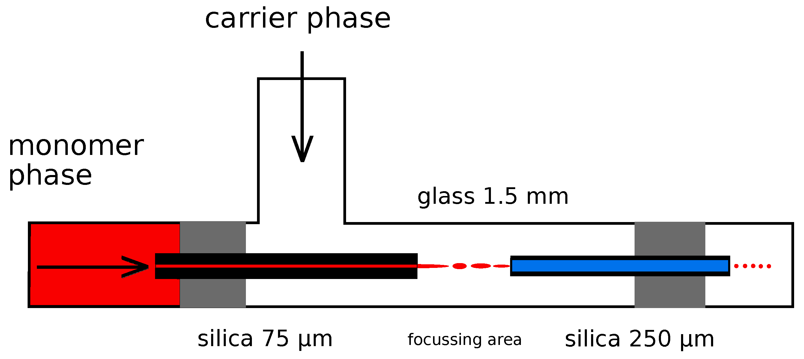
2.3. Droplet Generation and Thermal Polymerization
2.4. Droplet Generation and In Situ Photopolymerization
2.5. Assembly of Particles
3. Results
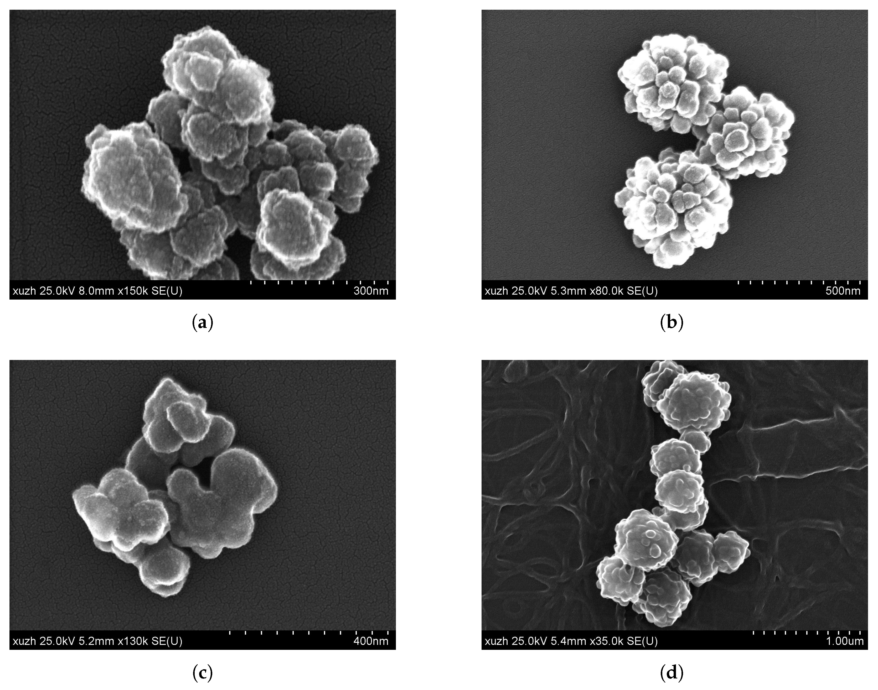
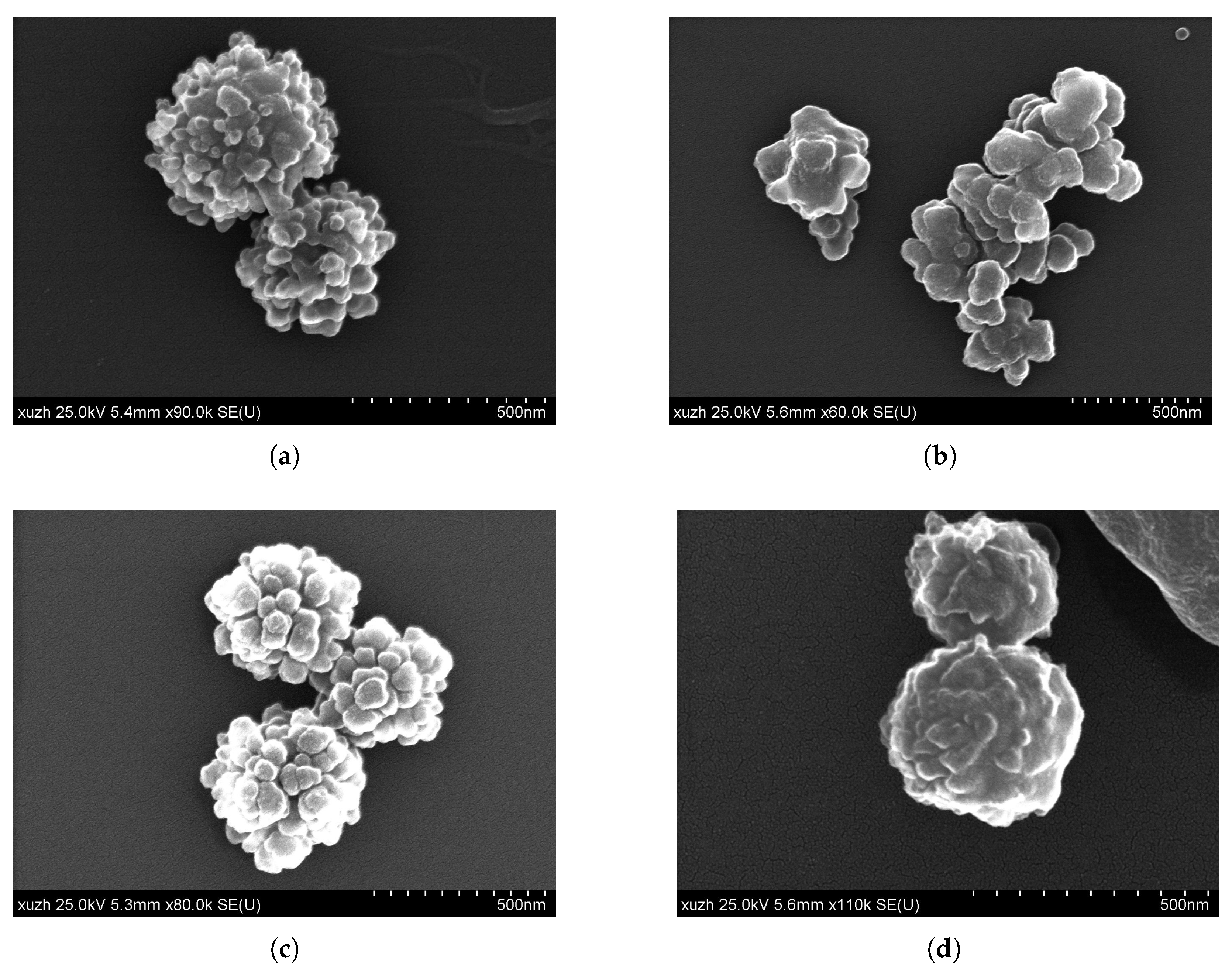
3.1. Textured Nanoparticles of Polymethylmethacrylate and Polydivinylbenzene
- The monomer phase consisted of 38% MMA, 62% toluene (volume fraction), and 11.6 mM AIBN.
- By means of the microfluidic hole-plate device (see Section 2.3 [28]), an emulsion was produced at flow rates of 240 µL/min (monomer) and 1500 µL/min (carrier) and piped into a thermostat held at 85 °C.
- After a certain incubation time, EGDMA and DVB were added. The reason why these crosslinking components were not present from the start in the monomer phase was due to the assumption that when they are added later, they can accumulate near the particle surface, facilitating wrinkle formation.
- With increasing reaction time, the mixture became increasingly turbid; after 4 h, it was removed from the thermostat. Coarse parts were removed manually; then, the suspension was centrifuged and washed several times, first with ethanol to extract remains of monomer and solvent and finally with water to remove the ethanol.
- The monomer phase consisted of DVB and toluene in varying quantities, and AIBN in a concentration of 60–120 mM.
- The carrier phase consisted of water with varying types and quantities of additives (surfactants and polyelectrolytes).
- Using the microfluidic hole-plate device, an emulsion was produced at flow rates of 150–200 µL/min (monomer) and 1500 µL/min (carrier) and piped into the thermostat held at 85 °C.
- After 90 min, the reaction mixture was removed from the thermostat and treated similar to MMA.
3.2. Hierarchically Constructed Particles of Poly-Acrylamid/TPGDA/MMA
3.2.1. Synthesis of PMMA Nanoparticles
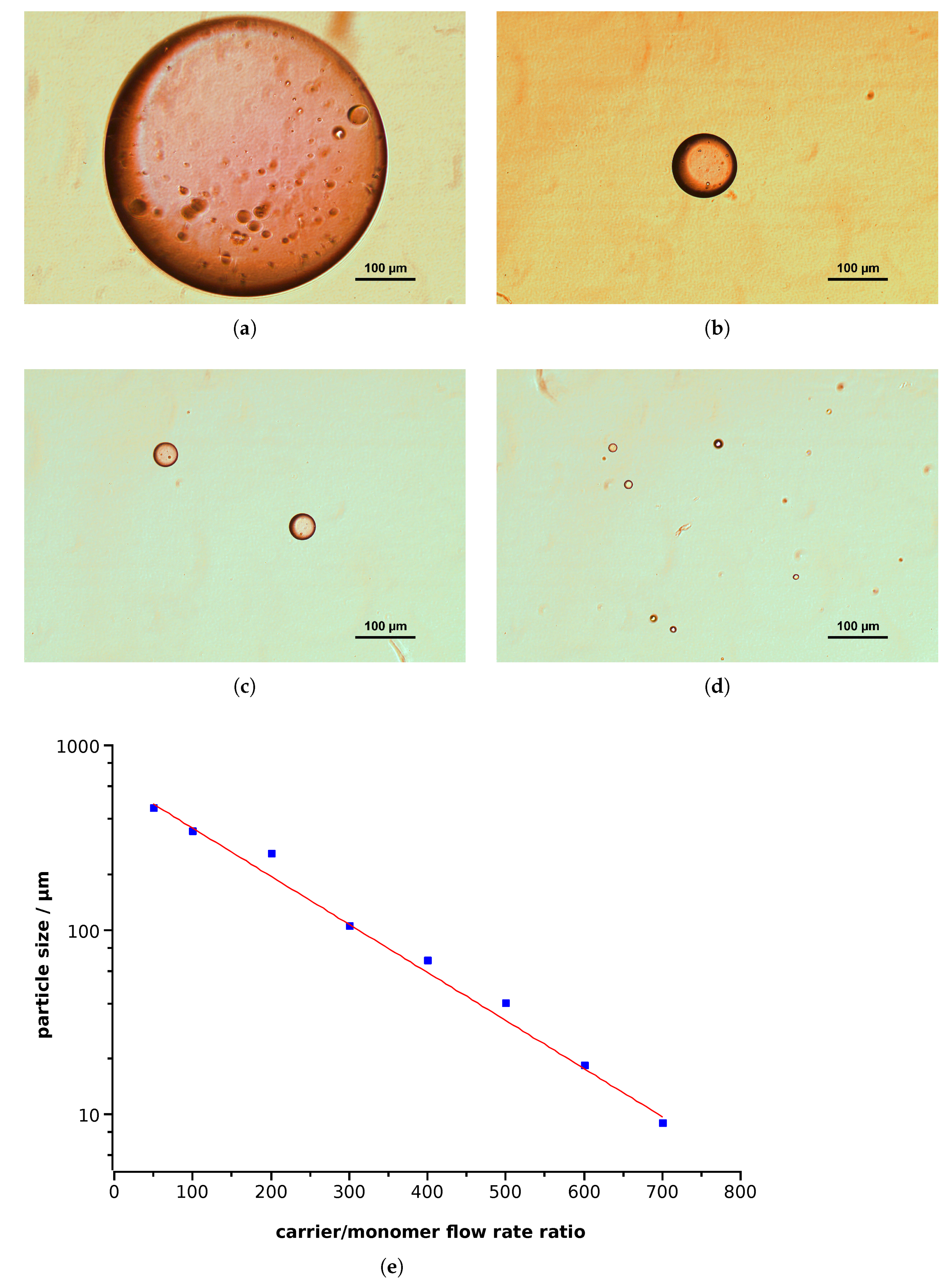
- The monomer phase consisted of 97% MMA, 3% EGDMA (volume fractions), and 30 mM AIBN. When indicated, Nile red was introduced to enable detection by fluorescence microscopy.
- The carrier phase consisted of water with variable amounts of poly-DADMAC.
- By means of the microfluidic hole-plate device, an emulsion was produced at variable flow rates and piped into the thermostat held at 97 °C.
- After 60 min, the reaction mixture was removed from the thermostat and treated as described.
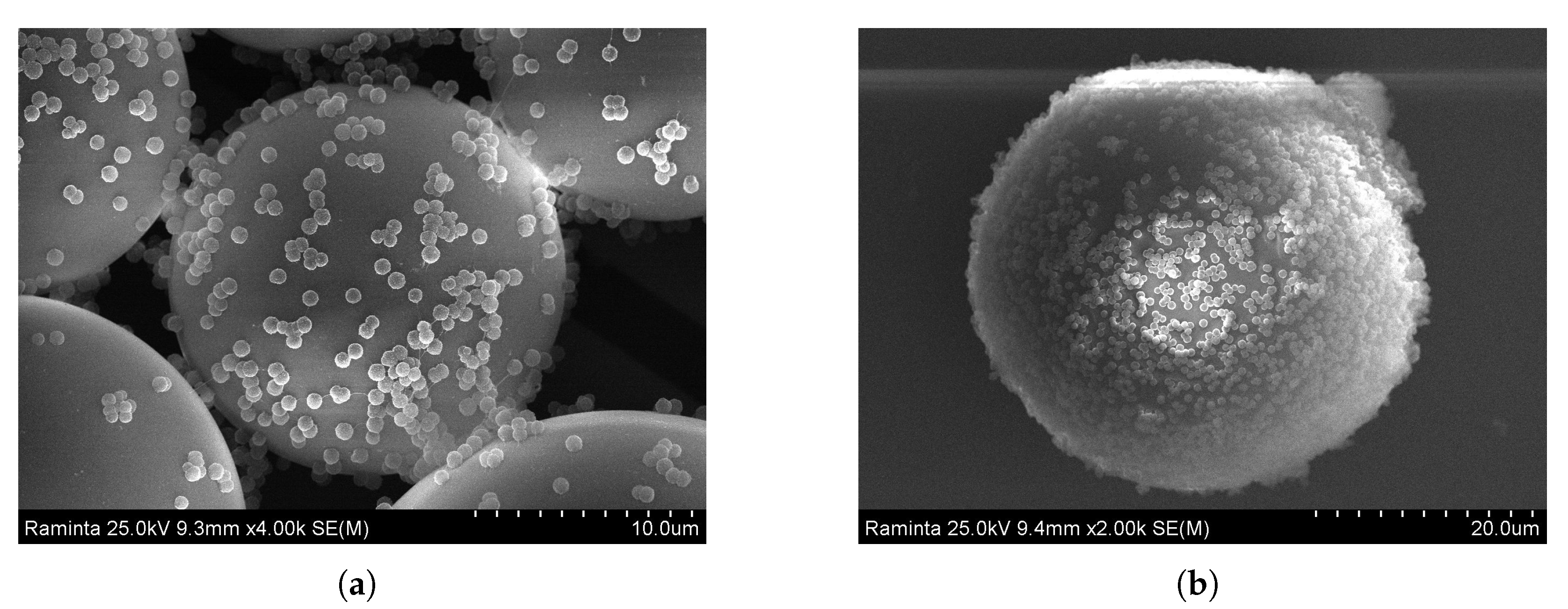
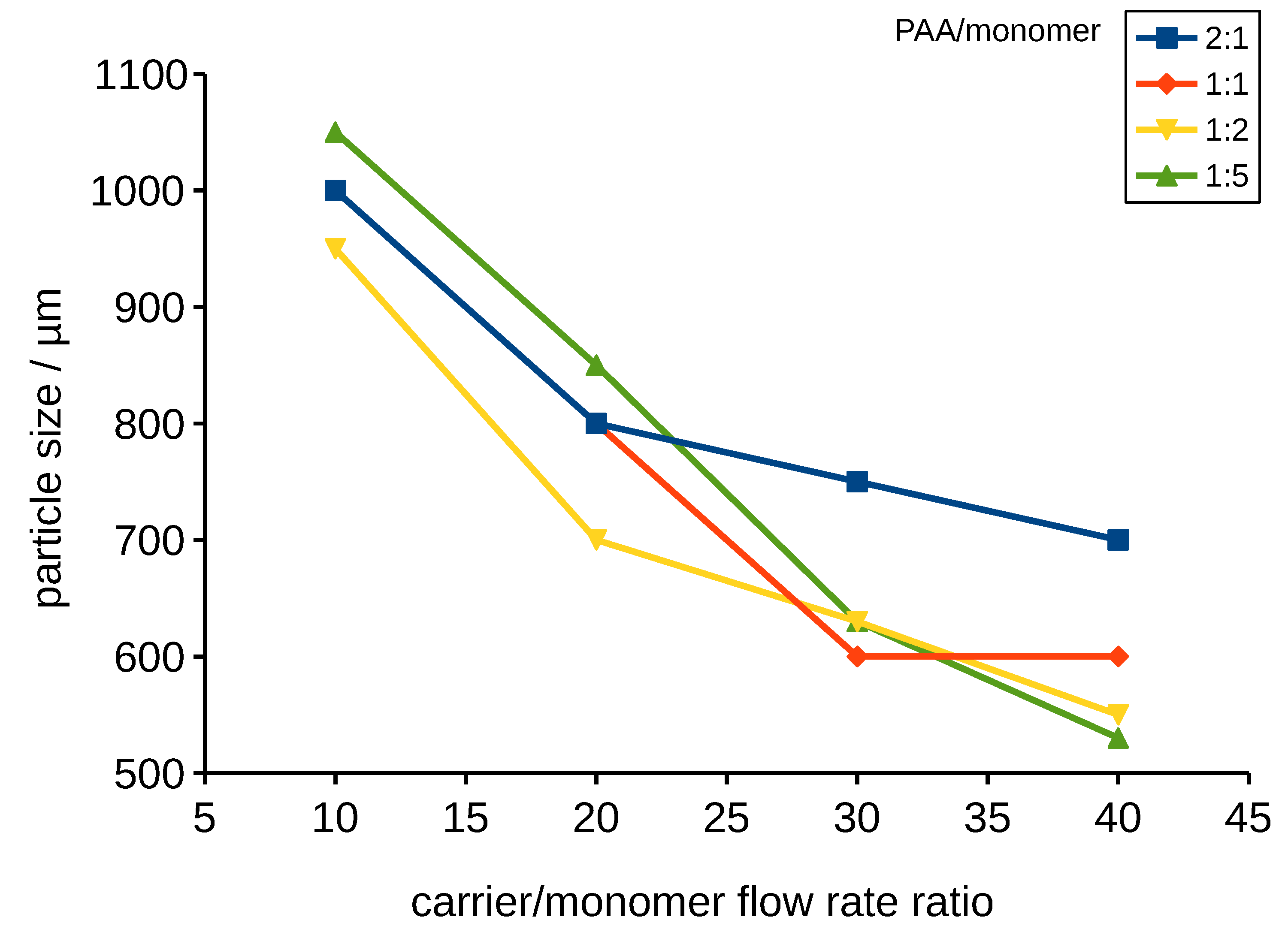
3.2.2. Synthesis of Poly-TPGDA Microparticles
3.2.3. Assembling of PMMA on Poly-TPGDA Particles
Polymer–Polymer Particle Bounding Efficiency Depends on Several Factors
- First, particle surfaces need to be highly charged in order to form strong electrostatic interactions. Therefore, it is important to functionalize both particle types. PMMA particles carrying the PDADMAC layer had a zeta potential of +35 mV. Poly-TPGDA particles were functionalized by copolymerization with acrylic acid, thus introducing a negative charge. The optimal concentration of acrylic acid in monomer phase was 10%. At lower contents, particle-binding was poor, whereas with 20%, the poly-TPGDA particles were more polydisperse.
- Other important factors are the concentration of smaller bound particles and incubation time. In order to allow both types of particles to closely contact, all assembling experiments were performed with a large excess of PMMA particles, and the mixture was incubated for 48 h. After this period, even the smaller particles had settled and bound to the surface of the lager ones (Figure 9).
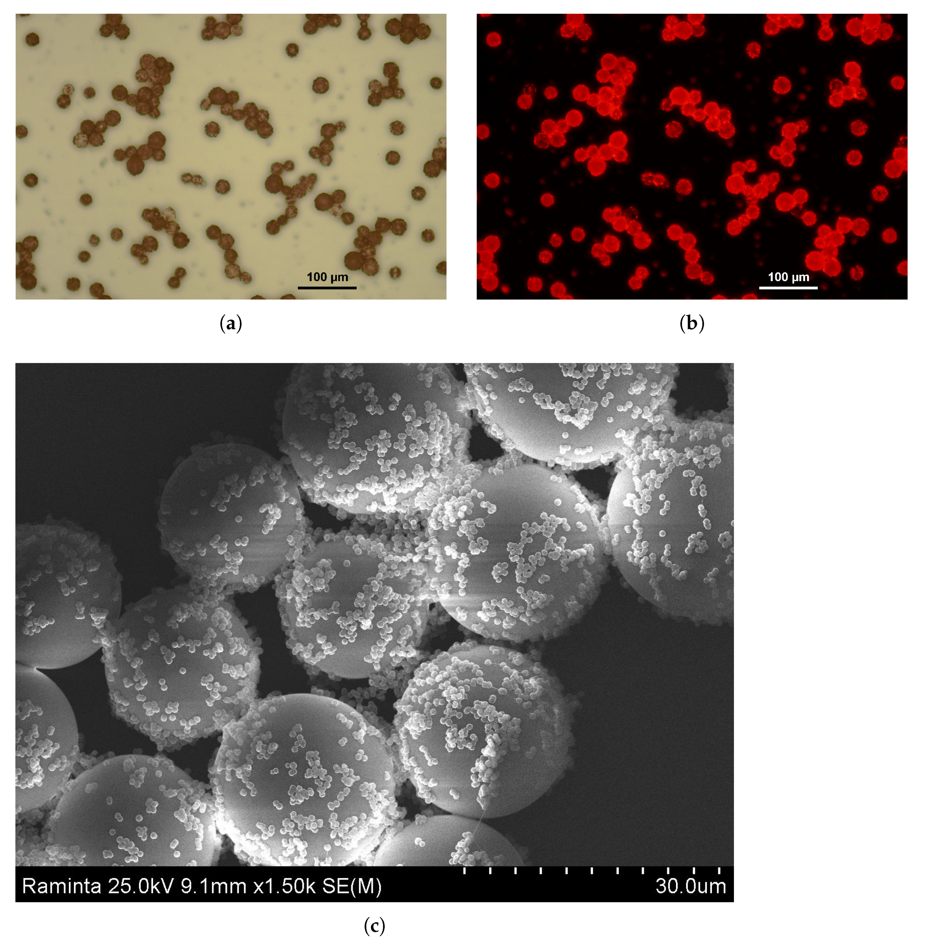
3.2.4. Synthesis of PAA Particles Containing Poly-MMA on Poly-TPGDA Particles
4. Discussion
4.1. Textured Nanoparticles
- The dilution effect of the monomer due to the high toluene content;
- Lower temperature and AIBN concentration;
- The presence of methanol in the carrier phase.
- Temperature: When temperature increases, the gel interval decreases but the Brownian motion increases.
- Gel interval is affected by monomer/crosslinker type and concentration, initiator type and concentration, and temperature.
- Initial size (substructure size) is affected by surfactant type and concentration, mixing conditions, and dwell time. Smaller particles move faster and collide more often.
- Effects that stabilize or destabilize the colloidal solution include electric surface potential, electrolyte concentration, and steric stabilization.
4.2. Hierarchically Constructed Particles
- Particles can be stored, portioned, weighed, and handled more easily.
- These aggregates can be dried and re-wet without damaging the composites inside.
- The hydrogel structure allows for the diffusion of molecules in- and outside and thereby mechanically shields the composites.
Author Contributions
Funding
Institutional Review Board Statement
Informed Consent Statement
Data Availability Statement
Acknowledgments
Conflicts of Interest
References
- Hussain, M.; Xie, J.; Hou, Z.; Shezad, K.; Xu, J.; Wang, K.; Gao, Y.; Shen, L.; Zhu, J. Regulation of Drug Release by Tuning Surface Textures of Biodegradable Polymer Microparticles. ACS Appl. Mater. Interfaces 2017, 9, 14391–14400. [Google Scholar] [CrossRef] [PubMed]
- Dobhal, A.; Kulkarni, A.; Dandekar, P.; Jain, R. A microreactor-based continuous process for controlled synthesis of poly-methyl-methacrylate- methacrylic acid (PMMA) nanoparticles. J. Mater. Chem. B 2017, 5, 3404–3417. [Google Scholar] [CrossRef]
- Chen, M.; Hu, W.; Liang, X.; Zou, C.; Li, F.; Zhang, L.; Chen, F.; Yang, H. A Facile All-Solution-Processed Surface with High Water Contact Angle and High Water Adhesive Force. ACS Appl. Mater. Interfaces 2017, 9, 23246–23254. [Google Scholar] [CrossRef] [PubMed]
- Xie, H.; Xu, W.; Fang, C.; Wu, T. Efficient and economical approach for flexible photothermal icephobic copper mesh with robust superhydrophobicity and active deicing property. Soft Matter 2021, 17, 1901–1911. [Google Scholar] [CrossRef] [PubMed]
- Starostin, A.; Strelnikov, V.; Valtsifer, V.; Lebedeva, I.; Legchenkova, I.; Bormashenko, E. Robust icephobic coating based on the spiky fluorinated Al2O3 particles. Sci. Rep. 2021, 11, 5394. [Google Scholar] [CrossRef]
- Li, M.; Joung, D.; Hughes, B.; Waldman, S.D.; Kozinski, J.A.; Hwang, D.K. Wrinkling Non-Spherical Particles and Its Application in Cell Attachment Promotion. Sci. Rep. 2016, 6, 30463. [Google Scholar] [CrossRef] [PubMed] [Green Version]
- Visaveliya, N.; Köhler, J.M. Microfluidic Assisted Synthesis of Multipurpose Polymer Nanoassembly Particles for Fluorescence, LSPR, and SERS Activities. Small 2015, 11, 6435–6443. [Google Scholar] [CrossRef]
- Klupp Taylor, R.N.; Bao, H.; Tian, C.; Vasylyev, S.; Peukert, W. Facile Route to Morphologically Tailored Silver Patches on Colloidal Particles. Langmuir 2010, 26, 13564–13571. [Google Scholar] [CrossRef]
- Yin, J.; Han, X.; Cao, Y.; Lu, C. Surface Wrinkling on Polydimethylsiloxane Microspheres via Wet Surface Chemical Oxidation. Sci. Rep. 2014, 4, 5710. [Google Scholar] [CrossRef]
- Zhao, T.; Qiu, D. One-Pot Synthesis of Highly Folded Microparticles by Suspension Polymerization. Langmuir 2011, 27, 12771–12774. [Google Scholar] [CrossRef]
- Liu, J.; Liu, Y.; Xue, Y.; Ren, Y.; Fan, X.; Wang, R.; Zhang, H.; Zhang, B.; Zhang, Q. Fabrication and characterization of controllable wrinkled-surface polymer microparticles. J. Mater. Sci. 2019, 54, 5852–5864. [Google Scholar] [CrossRef]
- Chew, N.Y.K.; Chan, H.-K. Use of Solid Corrugated Particles to Enhance Powder Aerosol Performance. Pharm. Res. 2001, 18, 1570–1577. [Google Scholar] [CrossRef] [PubMed]
- Cao, G.; Chen, X.; Li, C.; Ji, A.; Cao, Z. Self-Assembled Triangular and Labyrinth Buckling Patterns of Thin Films on Spherical Substrates. Phys. Rev. Lett. 2008, 100, 036102. [Google Scholar] [CrossRef] [Green Version]
- Hano, N.; Takafuji, M.; Ihara, H. One-pot preparation of polymer microspheres having wrinkled hard surfaces through self-assembly of silica nanoparticles. Chem. Commun. 2017, 53, 9147–9150. [Google Scholar] [CrossRef]
- Tan, W.K.; Araki, Y.; Yokoi, A.; Kawamura, G.; Matsuda, A.; Muto, H. Micro- and Nano-assembly of Composite Particles by Electrostatic Adsorption. Nanoscale Res. Lett. 2019, 14, 1–9. [Google Scholar] [CrossRef] [Green Version]
- Marschelke, C.; Diring, O.; Synytska, A. Reconfigurable assembly of charged polymer- modified Janus and non-Janus particles: From half- raspberries to colloidal clusters and chains. Nanoscale Adv. 2019, 1, 3715–3726. [Google Scholar] [CrossRef] [Green Version]
- Nakanishi, T.; Shen, Y.; Wang, J.; Li, H.; Fernandes, P.; Yoshida, K.; Yagai, S.; Takeuchi, M.; Ariga, K.; Kurth, D.G.; et al. Superstructures and superhydrophobic property in hierarchical organized architectures of fullerenes bearing long alkyl tails. J. Mater. Chem. 2010, 20, 1253–1260. [Google Scholar] [CrossRef]
- Thiruvengadathan, R.; Korampally, V.; Ghosh, A.; Ch, A.N.; Gangopadhyay, K.; Gangopadhyay, S. Nanomaterial processing using self-assembly-bottom-up chemical and biological approaches. Rep. Prog. Phys. 2013, 76, 066501. [Google Scholar] [CrossRef] [PubMed]
- Lunn, D.J.; Finnegan, J.R.; Manners, I. Self-assembly of “patchy” nanoparticles: A versatile approach to functional hierarchical materials. Chem. Sci. 2015, 6, 3663–3673. [Google Scholar] [CrossRef] [Green Version]
- Wang, Z.; Wang, H.; Cheng, M.; Li, C.; Faller, R.; Sun, S.; Hu, S. Controllable Multigeometry Nanoparticles via Cooperative Assembly of Amphiphilic Diblock Copolymer Blends with Asymmetric Architectures. ACS Nano 2018, 12, 1413–1419. [Google Scholar] [CrossRef] [Green Version]
- Moulin, E.; Armao, J.J.; Giuseppone, N. Triarylamine-Based Supramolecular Polymers: Structures, Dynamics, and Functions. Acc. Chem. Res. 2019, 52, 975–983. [Google Scholar] [CrossRef]
- Hanisch, A.; Gro¨schel, A.H.; Fo¨rtsch, M.; Drechsler, M.; Jinnai, H.; Ruhl, T.M.; Schacher, F.H.; Mu¨ller, A.H. Counterion-Mediated Hierarchical Self-Assembly of an ABC Miktoarm Star Terpolymer. ACS Nano 2013, 7, 4030–4041. [Google Scholar] [CrossRef] [PubMed]
- Jia, L.; Zhao, G.; Shi, W.; Coombs, N.; Gourevich, I.; Walker, G.C.; Guerin, G.; Manners, I.; Winnik, M.A. A design strategy for the hierarchical fabrication of colloidal hybrid mesostructures. Nat. Commun. 2014, 5, 3882. [Google Scholar] [CrossRef] [PubMed] [Green Version]
- Wang, J.; Le-The, H.; Wang, Z.; Li, H.; Jin, M.; van den Berg, A.; Zhou, G.; Segerink, L.I.; Shui, L.; Eijkel, J.C. Microfluidics Assisted Fabrication of Three- Tier Hierarchical Microparticles for Constructing Bioinspired Surfaces. ACS Nano 2019, 13, 3638–3648. [Google Scholar] [CrossRef] [Green Version]
- Liu, W.; Kappl, M.; Butt, H.-J. Tuning the Porosity of Supraparticles. ACS Nano 2019, 13, 13949–13956. [Google Scholar] [CrossRef] [Green Version]
- Yang, Q.; Miao, X.; Loos, K. Fabrication of Nano-Sized Hybrid Janus Particles from Strawberry-Like Hierarchical Composites. Macromol. Chem. Phys. 2018, 219, 1800267. [Google Scholar] [CrossRef]
- Fairbanks, B.D.; Schwartz, M.P.; Bowman, C.N.; Anseth, K.S. Photoinitiated polymerization of PEG-diacrylate with lithium phenyl-2,4,6-trimethylbenzoylphosphinate: Polymerization rate and cytocompatibility. Biomaterials 2009, 30, 6702–6707. [Google Scholar] [CrossRef] [PubMed] [Green Version]
- Koehler, J.M.; Moeller, F.; Schneider, S.; Guenther, P.M.; Albrecht, A.; Gross, G.A. Size-tuning of monodisperse PMMA nanoparticles by micro-continuous-flow polymerization using a silicon micro-nozzle array. Chem. Eng. J. 2011, 167, 688–693. [Google Scholar] [CrossRef]
- Serra, C.A.; Khan, I.U.; Chang, Z.; Bouquey, M. Engineering Polymer Microparticles by Droplet Microfluidics. J. Flow Chem. 2013, 3, 66–75. [Google Scholar] [CrossRef] [Green Version]
- Serra, C.A.; Chang, Z. Microfluidic-Assisted Synthesis of Polymer Particles. Chem. Eng. Technol. 2008, 31, 1099–1115. [Google Scholar] [CrossRef]
- Köhler, J.M.; Kraus, I.; Faerber, J.; Serra, C. Continuous-flow preparation of nanoporous metal/polymer composite particles by in situ synthesis of silver nanoparticles in photopolymerized acrylate/diethylene glycol droplets. J. Mater. Sci. 2013, 48, 2158–2166. [Google Scholar] [CrossRef]
- Kronfeld, K.-P.; Ellinger, T.; Köhler, J.M. Microfluidically prepared sensor particles for determination of chloride by fluorescence quenching of matrix-embedded lucigenin. SN Appl. Sci. 2020, 2, 366–373. [Google Scholar] [CrossRef] [Green Version]
- Visaveliya, N.; Köhler, J.M. Role of Self-Polarization in a Single-Step Controlled Synthesis of Linear and Branched Polymer Nanoparticles. Macromol. Chem. Phys. 2015, 216, 1212–1219. [Google Scholar] [CrossRef]
- Visaveliya, N.; Köhler, J.M. Control of Shape and Size of Polymer Nanoparticles Aggregates in a Single-Step Microcontinuous Flow Process: A Case of Flower and Spherical Shapes. Langmuir 2014, 30, 12180–12189. [Google Scholar] [CrossRef] [PubMed]
- Kim, O.H.; Lee, K.; Kim, K.; Lee, B.H.; Choe, S. Optimum conditions for preparing micron-sized PMMA beads in the dispersion polymerization using PVA. Colloid Polym. Sci. 2006, 284, 909–915. [Google Scholar] [CrossRef]
- Shim, S.E.; Kim, K.; Oh, S.; Choe, S. Preparation of Ultra Fine Poly(methyl methacrylate) Microspheres in Methanol-enriched Aqueous Medium. Macromol. Res. 2004, 12, 240–245. [Google Scholar] [CrossRef]
- Seo, M.; Nie, Z.; Xu, S.; Mok, M.; Lewis, P.C.; Graham, R.; Kumacheva, E. Continuous Microfluidic Reactors for Polymer Particles. Langmuir 2005, 21, 11614–11622. [Google Scholar] [CrossRef]
- Hait, S.K.; Moulik, S.P. Determination of Critical Micelle Concentration (CMC) of Nonionic Surfactants by Donor–Acceptor Interaction with Iodine and Correlation of CMC with Hydrophile–Lipophile Balance and Other Parameters of the Surfactants. J. Surfactants Deterg. 2001, 4, 303–309. [Google Scholar] [CrossRef]
- Peltonen, L.; Hirvonen, J.; Yliruusi, J. The Behavior of Sorbitan Surfactants at the Water–Oil Interface: Straight-Chained Hydrocarbons from Pentane to Dodecane as an Oil Phase. J. Colloid Interface Sci. 2001, 240, 272–276. [Google Scholar] [CrossRef]


| Figure | EGDMA | DVB | Incubation Time | Particle Size | Substructure |
|---|---|---|---|---|---|
| ppm | % | min | nm | nm | |
| Figure 1a | 680 | 6.8 | 1 | 147 | 21 |
| Figure 1b and Figure 2c | 680 | 6.8 | 2 | 426 | 73 |
| Figure 1c | 680 | 6.8 | 3 | 95 | n.a. |
| Figure 1d | 680 | 6.8 | 5 | 496 | 86 |
| Figure 2a | 680 | 0 | 2 | 434 | 44 |
| Figure 2b | 0 | 6.8 | 2 | n.a. | 126 |
| Figure 2d | 0 | 0 | n.a. | 354 | 44 |
| Figure | Surfactant | Toluene | Particle Size | Substructure |
|---|---|---|---|---|
| Volume Fraction | nm | nm | ||
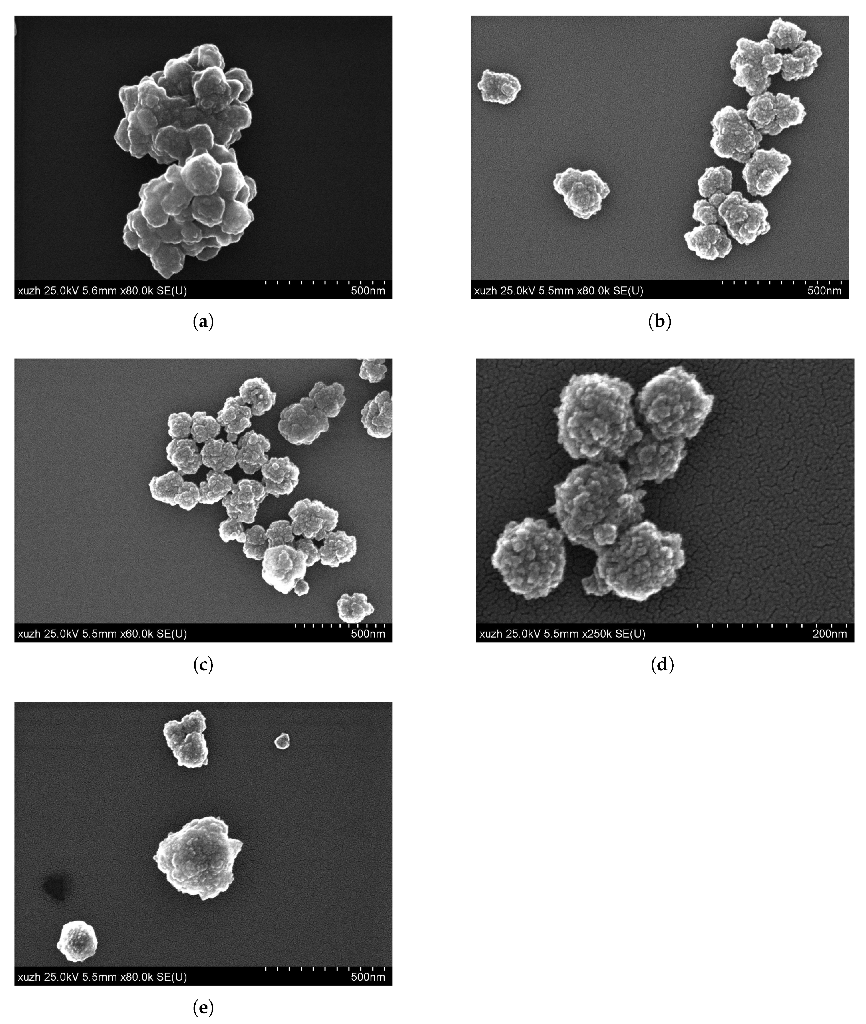
| Figure 3a | Brij52, 81.5 mM | 67% | 214 | 14 |
| Figure 3b | Span20, 86.6 mM | 67% | 172 | 20 |
| Figure 4a | Span 20, 173.3 mM | 67% | 121 | 26 |
| Figure 4b | Span 20, 173.3 mM | 50% | 182 | 18 |
| Figure 4c | Span 20, 173.3 mM | 33% | 185 | 26 |
| Figure 4d | Span 20, 173.3 mM | 25% | 100 | 11 |
| Figure 4e | Span 20, 173.3 mM | 0% | 164 | 19 |
Publisher’s Note: MDPI stays neutral with regard to jurisdictional claims in published maps and institutional affiliations. |
© 2021 by the authors. Licensee MDPI, Basel, Switzerland. This article is an open access article distributed under the terms and conditions of the Creative Commons Attribution (CC BY) license (https://creativecommons.org/licenses/by/4.0/).
Share and Cite
Kronfeld, K.-P.; Mazetyte-Stasinskiene, R.; Zheng, X.; Köhler, J.M. Textured and Hierarchically Constructed Polymer Micro- and Nanoparticles. Appl. Sci. 2021, 11, 10421. https://doi.org/10.3390/app112110421
Kronfeld K-P, Mazetyte-Stasinskiene R, Zheng X, Köhler JM. Textured and Hierarchically Constructed Polymer Micro- and Nanoparticles. Applied Sciences. 2021; 11(21):10421. https://doi.org/10.3390/app112110421
Chicago/Turabian StyleKronfeld, Klaus-Peter, Raminta Mazetyte-Stasinskiene, Xuejiao Zheng, and Johann Michael Köhler. 2021. "Textured and Hierarchically Constructed Polymer Micro- and Nanoparticles" Applied Sciences 11, no. 21: 10421. https://doi.org/10.3390/app112110421
APA StyleKronfeld, K.-P., Mazetyte-Stasinskiene, R., Zheng, X., & Köhler, J. M. (2021). Textured and Hierarchically Constructed Polymer Micro- and Nanoparticles. Applied Sciences, 11(21), 10421. https://doi.org/10.3390/app112110421