Article

Fabrication of Sinusoidal Microstructures on Curved Copper Surface by Ultra-Precision Diamond Cutting with a Rotary B-Axis and Fast Tool Servo System

1
Center for Precision Engineering, Harbin Institute of Technology, Harbin 150001, China
2
Key Laboratory of Bionic Engineering (Ministry of Education), Jilin University, Changchun 130022, China
*
Author to whom correspondence should be addressed.
Appl. Sci. 2021, 11(21), 10302; https://doi.org/10.3390/app112110302
Submission received: 4 October 2021 / Revised: 29 October 2021 / Accepted: 1 November 2021 / Published: 2 November 2021
(This article belongs to the Special Issue Precision Manufacturing and Intelligent Machine Tools)

Abstract

:
While curved surface microstructures have wide applications in optical components and devices, how to achieve high machining accuracy of the microstructures is crucial for their applications. In the present work, we fabricate sinusoidal modulation microstructures on a curved copper surface by ultra-precision diamond cutting, with the combination of a rotary B-axis and a fast tool servo system. Specifically, tool path planning, together with the consideration of a curved, sinusoidal surface meshing and tool tip arc segmentation compensation, is carried out. Preliminary cutting experiments are firstly carried out on a homemade four-axis ultra-precision lathe, which demonstrates the advantages of additionally applying the rotary B-axis in suppressing burr formations and over-cutting phenomenon over the sole utilization of the fast tool servo system. Subsequent experiments are carried out to evaluate the effects of feed rate and the number of sampling points on the machining accuracy of the microstructures under the combination of a rotary B-axis and a fast tool servo system. With the optimized machining parameters, sinusoidal modulation microstructures, which have a wavelength of 700.6 μm, a peak-to-valley of 18.7 μm, a surface roughness of 18.9 nm and a deviation of profile tolerance of 4.326 μm, are successfully fabricated on a curved copper surface with a face radius of 10 mm and a curvature radius of 500 mm.

1. Introduction

Surface texturing has been demonstrated to be a promising technique for enhancing the functionalities and performance of components and parts [1,2,3]. In particular, curved surface microstructures are highly desired in optical fields, such as the microlens arrays used in the camera of phones [4] and the Fresnel lenses used in solar cells [5]. While the accuracy of microstructures, such as contour accuracy and surface finish, has a strong impact on the performance of the microstructured surface, fabricating high-precision microstructures with feature sizes down to micrometers is challenging. In particular, ultra-precision diamond cutting equipped with a fast tool servo (FTS) system has been demonstrated to be a promising technique for surface texturing for a variety of materials. Liu et al. [6] introduced a compact FTS used in ophthalmology for advanced lens processing, which has a frequency response of 100 Hz and a repeat positioning accuracy of 7.5 μm. Rakuff et al. [7] developed a remote precision FTS system with a maximum acceleration of 260 m∗s−2 and a bandwidth of up to 140 Hz, which can realize a surface roughness between 20 and 30 nm for aluminum. Li et al. [8] designed an FTS system with force sensing and controlling based on the flexible deformation mechanism. Yong et al. [9] deduced the tool radius compensation algorithm for complex microstructure fabrication by using FTS and conducted experimental research on the fabrication of aspheric arrays microstructures on aluminum cylinders. Huang et al. [10] designed a four-axis linkage tool-workpiece motion system and considered the lens design, tool geometry and roller parameters in the tool path generation, which led to the realization of an average surface roughness of 8.25 nm of lens microstructures fabricated on a brass roller by using the FTS system. Zhong et al. [11] proposed a new data processing algorithm to achieve an overall contour error of less than 2 μm for microstructures fabricated on a brass surface by using the FTS system. Zhao et al. proposed a high-precision two-degrees-of-freedom compliant mechanism.
However, achieving the fabrication of high-precision surface textures on a curved surface with a large curvature radius by diamond cutting is still challenging. Specifically, in the fabrication of a sinusoidal modulation surface on a curved surface with a large curvature radius by solely using the FTS system, the height difference exceeds the stroke of the FTS from a certain position, which thus requires the extension of the stroke of the FTS. However, the stroke of the FTS system is severely limited by the high-frequency characteristics of the system. Keong et al. presented a novel FTS diamond turning method with layered tool trajectories, which enables the extending of the limited stroke length to fivefold of its maximum possible stroke length [12]. Liu et al. presented a long-stoke FTS to obtain a large-amplitude tool motion, which led to the fabrication of a sinusoidal surface with five sinusoidal waves and an amplitude of 20 μm on 6061 aluminum [13]. More recently, Yang et al. fabricated a multiscale optical surface by diamond turning using the high-dynamic performance of FTS and the long stroke of a slow tool servo [14]. Pu et al. proposed a dual-axial FTS diamond turning method for the one-step fabrication of hierarchical micro-nano-structured surfaces, in which the additional x-axial motion is effective for deterministic generation of a variety of secondary structures [15]. In addition, the currently utilized method of tool path planning for the fabrication of modulation microstructures on curved surfaces generally has the disadvantages of complex processing procedures and low processing efficiency, which subsequently lowers the machining efficiency. Cai et al. demonstrated that the tool path has a strong influence on the surface form error, such as roughness, waviness and profile errors [16]. Liu et al. found that the machining errors have a strong influence on the optical performance of optical aspheric components machined by FTS [17]. More recently, Zuo et al. developed a new tool path generation method and discussed the tool geometry parameter selection for diamond turning utilizing non-zero rake angle tools, based on which a typical freeform surface is fabricated [18]. Liu et al. proposed an optimization method of tool path generation based on the interpolation of the lens edge, which can effectively reduce the overcut of the lens edge [19].
Therefore, in view of the above issues, in the present work, we propose a novel tool path planning method with the consideration of tool tip arc segmentation compensation for the fabrication of sinusoidal modulation microstructures on curved surfaces by diamond cutting. Furthermore, a rotary B-axis is introduced to work together with the FTS system for the fabrication of the microstructures. The influences of machining parameters on the machining precision of the microstructures are also evaluated. Finally, high-precision sinusoidal modulation microstructures are successfully fabricated on a curved copper surface using the optimized parameters.

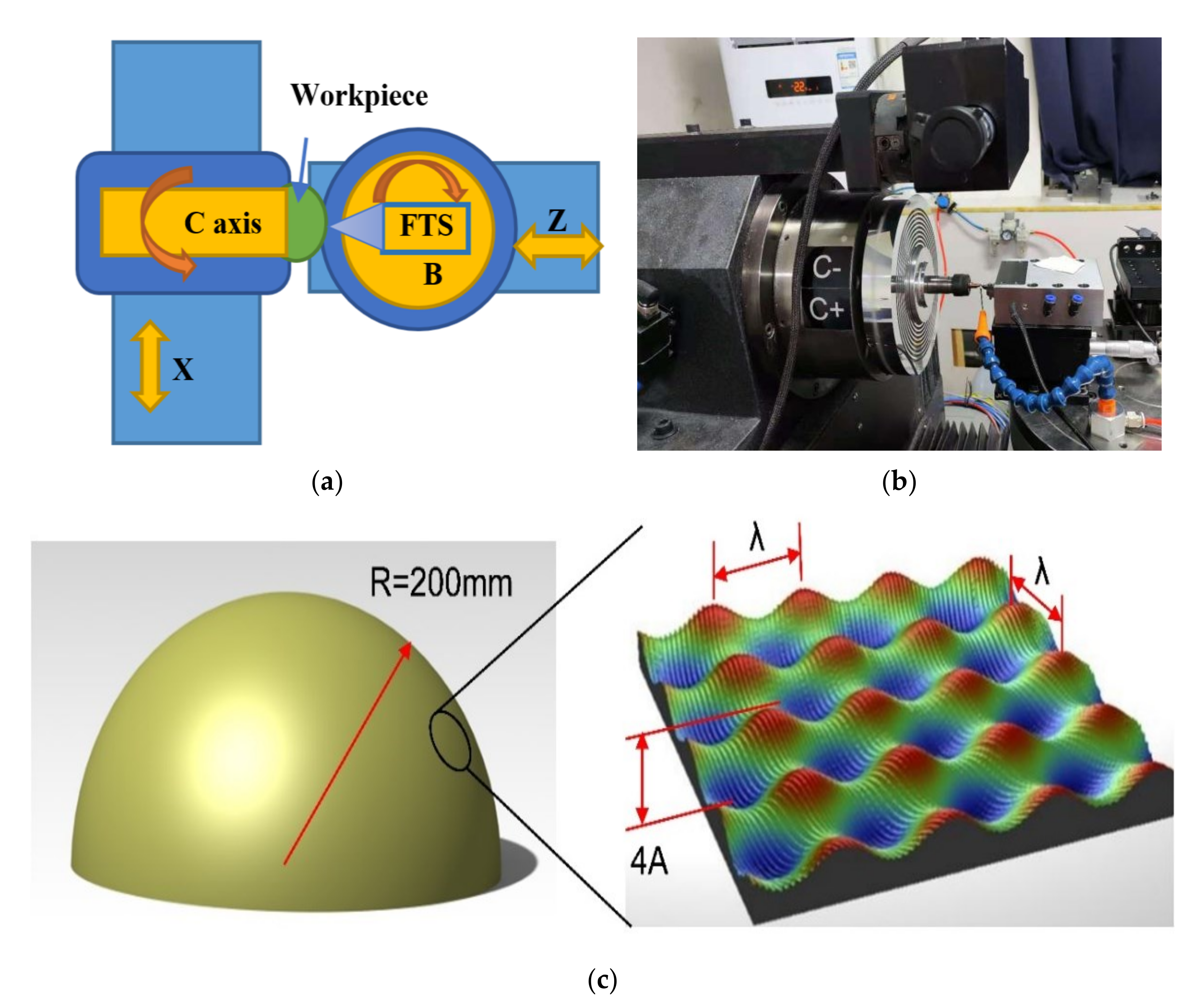
2. Experimental Setup

Figure 1a shows the layout of the four-axis ultra-precision lathe, which contains an air bearing spindle (C-axis), a rotary table (B-axis) and two cross slides for linear motion (X-axis and Z-axis). Figure 1b presents the realized homemade four-axis ultra-precision lathe produced in the Center for Precision Engineering, Harbin Institute of Technology, China. The specifications of the lathe are listed in Table 1. Figure 1c illustrates the configuration of sinusoidal microstructures fabrication, which demonstrates that sinusoidal microstructures are fabricated on a curved surface with a curvature of 200 mm, and the sinusoidal microstructures have a peak to peak distance of λ = 700 μm and peak to valley distance 4A = 18 μm.
The FTS system has a stroke of 32 μm, a closed-loop linearity less than 0.1% full scale and a closed-loop resolution of 10 nm. Furthermore, the repositioning accuracy is within 10 nm, the load-free resonance frequency is 4 kHz, and the bandwidth of the system is higher than 1 kHz. For the fabrication of a sinusoidal modulation microstructure, the output amplitude of a sinusoidal sweep signal is 5 μm, and the bandwidth of the system is higher than 500 Hz. A single crystal natural diamond tool with a round arc edge is utilized for the fabrication of the microstructures. To avoid the interference between the diamond tool and the curved workpiece, the geometric size of the diamond tool needs to be selected according to the minimum feature size of the microstructure surface. Table 2 lists the tool parameters used in the experiment. All the experiments are conducted three times, which demonstrates high repeatability.

3. Results and Discussion

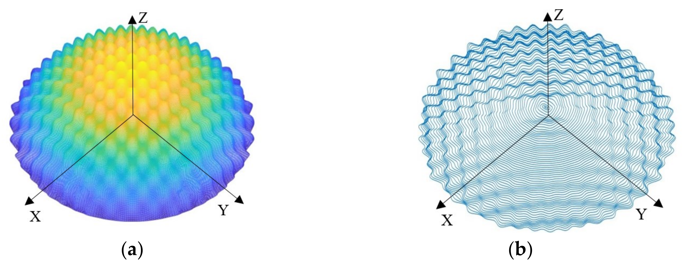
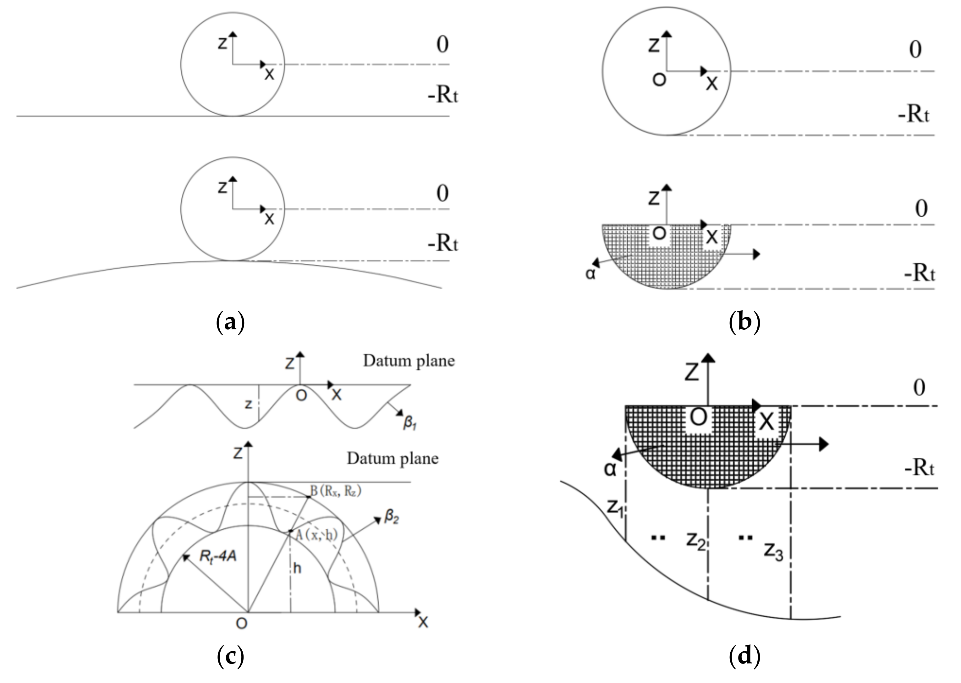
3.1. Tool Path Generation for Sinusoidal Microstructure Fabrication on Curved Surface

The tool path generation for sinusoidal microstructure fabrication on a planar surface is carried out first. The design of the planar sinusoidal grid is completed in the Cartesian coordinate system, and the Z coordinate of each point can be represented by the corresponding X and Y coordinates, the independent sine waves in which are superimposed to form a sine grid. Therefore, the Z coordinate of each point can be expressed by Equation (1):
Z = f ρ , θ = A x sin 2 π ρ cos θ λ x + A y sin 2 π ρ cos θ λ y                                      
where A is the distance from the projection of any point of the tool path on the X–Y plane to the coordinate origin (μm) and λ is the angle of rotation relative to the initial point (°). When ρ and θ take different values according to a certain rule, a tool path is formed. The curved, sinusoidal grid is formed by superimposing independent sine waves in the X and Y directions on the base surface of the curved surface. For the curved surface microstructure fabrication using the FTS system, the movement in the Z direction can be replaced by the fast tool auxiliary axis. During the machining process, the stroke of the diamond tool fixed on the FTS post is superimposed on the ball trajectory, while the FTS device achieves a high-frequency response in the Z direction. The generated sine mesh surface and tool path are shown in Figure 2.
Furthermore, to avoid the over-cutting phenomenon, the compensation amount of the tool nose trajectory is calculated, which is needed for obtaining the movement trajectory of the arc center of the tool nose as the coordinate of the tool location point. In order to simplify the calculation algorithm, save the time of generating data points and improve the processing efficiency, a new compensation method based on the tool tip arc segmentation is established. The generation method of tool path for the fabrication of sinusoidal surface microstructure is illustrated in Figure 3.
In the programming coordinate system for a spherical surface, the highest point of the spherical surface is −Rt, and the position of the center point of the tool tip arc is zero. In particular, the starting position of any point in the machining process of sinusoidal microstructures is the zero position in the program coordinate, as shown by the dotted line zero position in Figure 3a. According to the analysis of the actual processing situation, only the arc edge of the lower half can realize the turning operation, so only the lower half-circle area needs to be analyzed. In order to save calculation time of the tool path generation, according to the radius of the tool tip arc used, the discretization accuracy is set as e−5, which can ensure the calculation of the corresponding Z-direction distance at least every 7 nm in the process of generating data points. Therefore, the interval is set between −Rt:Rt according to the discretization accuracy of e−5, and the semi-circular region is discretized by dispersing the points to obtain the position point parameter matrix relative to the zero point, as shown in Figure 3b.

3.2. Influence of Rotary B-Axis on the Microstructure Fabrication

Preliminary cutting experiments are firstly performed to evaluate the influence of applying the rotary B-axis on the machining precision of sinusoidal microstructures on a curved surface. Firstly, the spherical datum surface with a surface radius of 2 mm and a curvature radius of 200 mm is obtained by diamond cutting, and the machining parameters are: the minimal cutting depth is 2 μm, the feed rate is 5 μm/r and the spindle speed is 1200 r/s. Figure 4a presents the machined surface morphology of the curved surface characterized by a Zygo NewView 9000 white light interferometer and Vision 32 software, which demonstrates a surface roughness, Sa, of 10 nm. Figure 4b further plots the profile of the machined curve within a measurement range of 883.6 μm, as well as the fitting curve colored in red. Specifically, the sampling points are selected on the X-axis within a measurement range of 883.6 μm, and the values of the sampling points on the Y-axis within a range of −0.3 to 0.2 μm are utilized for fitting the curvature of the machined curved surface. Figure 4b indicates that the fitted curvature radius is 199.999 mm, which is very close to the designed value of 200 mm, which provides a good basis for the following fabrication of sinusoidal microstructures on the machined curved surface. The above results indicate a high profile accuracy, as well as the ultra-low surface roughness of the machined curved surface, which falls into the regime of ultra-precision machining.
Then, sinusoidal microstructures are fabricated on the spherical datum surface. The machining parameters for the microstructure fabrication are typical as a feed rate f of 10 μm/r, a number of sampling point P of 7200 d/r and a minimal cutting depth of 3 μm. Figure 5 presents the profiles of fabricated sinusoidal microstructures by different machining strategies. Note that the measurement range of Figure 5b is smaller than that of Figure 5a, intending to present an enlarged view of the machining characteristics for the strategy of jointly using the FST system and the rotary B-axis.
It is seen from Figure 5 that the surface quality in terms of surface roughness and surface error for the microstructures fabricated by solely using the FST system is lower than that by jointly using the FST and rotary B-axis. Firstly, the burr formation is significantly suppressed by using the rotary B-axis. Figure 5a shows that there are burrs formed in the transition section of the sinusoidal structure for the strategy of solely using the FST system. In contrast, the burrs are rather limited for the strategy of jointly using the FST system and rotary B-axis. Second, the measured surface roughness for the strategy of jointly using the FST and rotary B-axis is 46.7 nm, which is lower than that of 59.6 nm for the strategy of solely using FST is 59.6 nm. Thirdly, Figure 5a demonstrates that most of the outer circle of the curved surface is not cut off completely, which is not observed for the strategy of jointly using the FST and rotary B-axis. The reason for the lower surface quality for the strategy of solely using the FST is that during the machining process, the cutting force gradually changes with the change of the contact point of the tool tip with the workpiece, and the unstable cutting state leads to abnormal chip formation and deteriorated machined surface quality. For the spherical surface with a large curvature radius, the interference of the diamond tool with the workpiece in the Z-direction leads to an over-cut of the machined surface, thus changing the contour of the microstructure. The application of the rotary B-axis transforms the turning by cutting tip into the turning by cutting edge. In particular, in the FTS turning with a semi-circular diamond cutting tool, the turning by the cutting edge leads to a lowered cutting force, suppressed plastic deformation and burr formation, thus improving the machined surface quality.

3.3. Influence of Machining Parameters on the Microstructure Fabrication

Since the surface roughness of the machined microstructures with the assistance of the rotary B-axis is still high at 46.7 nm, the following optimization of machining parameters is carried out. Figure 6 shows the profiles of the machined microstructures under the feed rates of 8 and 5 μm/r, indicating that the feed rate has a trivial influence on the contour accuracy of the microstructures. However, the measured surface roughness is 17.9 and 25.6 nm for the feed rates of 8 and 5 μm/r, respectively. Therefore, a feed rate of 8 μm/r is selected for its higher surface roughness, as well as high machining efficiency.
Figure 7 presents the profiles of machined microstructures under the number of sampling points of 7200 and 5700 d/r. Figure 7 shows that the machining accuracy with the number of sampling points of 5700 d/r is lower than that of 7200 d/r in terms of severe deformation of the sinusoidal microstructures, a visible connection between sinusoidal grids and irregular contour, etc. Furthermore, the surface roughness for the number of sampling points of 5700 d/r is 57.8 nm, which is significantly higher than that of 17.9 nm for the number of sampling points of 7200 d/r. Therefore, the number of sampling points of 7200 d/r is selected for its higher surface roughness.

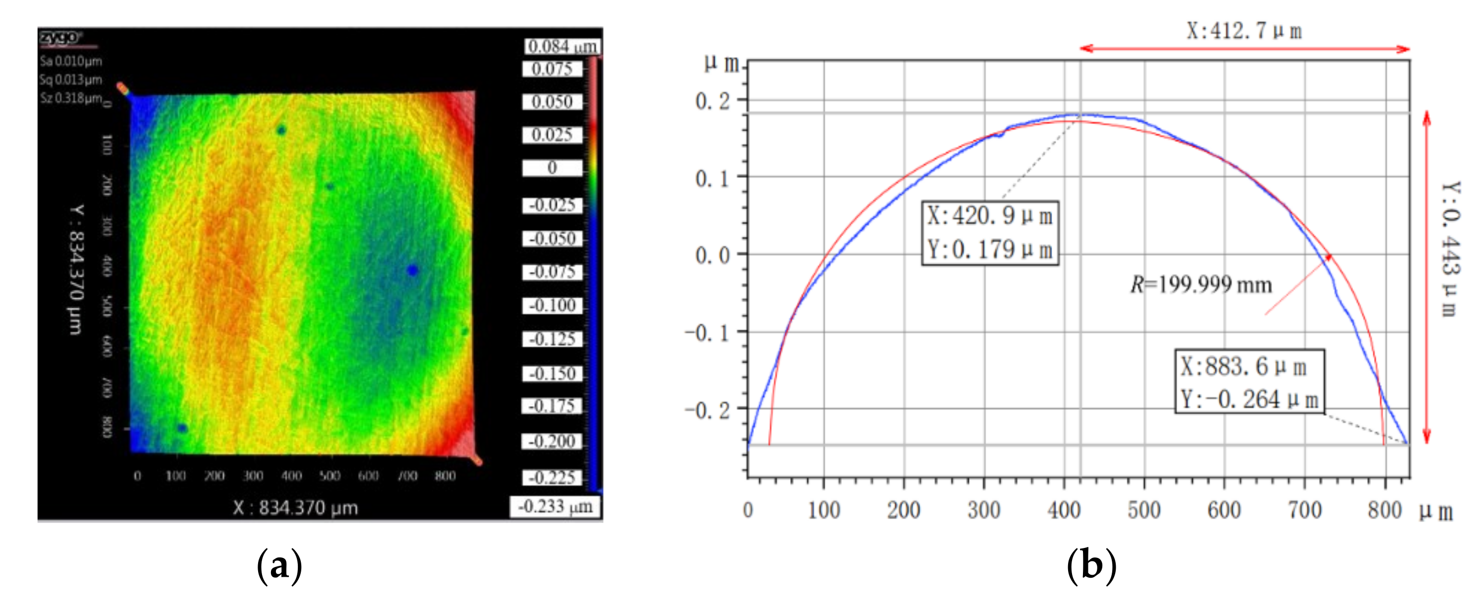
3.4. Fabrication of High Precision Sinusoidal Microstructures

The above investigations indicate that the optimized machining parameters for fabricating sinusoidal microstructures on a curved surface include a feed rate of 8 μm/r, a number of sampling points of 7200 d/r and a minimal cutting depth of 4 μm. With the optimized machining parameters, high precision sinusoidal microstructures are fabricated on a curved copper surface with a surface radius of 10 mm and a curvature radius of 500 mm. Before the fabrication of sinusoidal microstructures, a cleaning pass is performed to obtain an ultra-smooth curved surface with a curvature of 200 mm, similar to that shown in Figure 4. Figure 8 presents the finished part with sinusoidal modulation microstructures. Note that the figure shows some variations in surface quality, which are caused by the contaminations attached to the surface. Furthermore, the oxidation of the machined surface leads to the “debris” in black shown on the surface.
Figure 9a presents the profile of the as-fabricated sinusoidal microstructures by a white light interferometer, which demonstrates that the sinusoidal grid microstructures on a curved surface are arranged regularly, and the shape of the sinusoidal grid has a high degree of consistency. Furthermore, the joints between neighboring sinusoidal girds are flat, and the surface is basically free of impurities. Figure 9b also indicates that there is no burr formed on the microstructures. Furthermore, there are basically no scratches observed on the workpiece surface, demonstrating the effectiveness of applying the rotary B-axis in suppressing the over-cutting phenomenon. The surface roughness of the microstructured surface is 18.9 nm.
The two-dimensional profile of the sinusoidal microstructures fabricated on a curved surface is extracted, as shown in Figure 10. The amplitude and wavelength of the sinusoidal grid structures are measured. The wavelength and the peak-to-valley of the sinusoidal grid structure are 700.6 and 18.7 μm, respectively.
The contour deviation, ST, is defined as the evaluation parameter for the contour error of the curved, sinusoidal mesh. According to the principle of surface reconstruction, the calculation of the ST is performed by comparing the actual machined surface with the corresponding ideal machined surface through frequency spectrum conversion simulation. Firstly, the ideal workpiece surface profile is derived by using the Butterworth low-pass filter in the white light interferometer. Then the spectrogram of the ideal machined surface is obtained using the Fourier transform. Next, the frequency corresponding to the ideal machined surface is removed by using spectral symmetry. Finally, the contour error of the corresponding machined area is obtained by performing an inverse Fourier transform, as shown in Figure 11, which indicates a contour deviation ST of 4.326 μm. While the current work demonstrates the effectiveness of applying the rotary B-axis together with FTS in the fabrication of high precision microstructures on a curved surface, systematical investigations on the influence of machining parameters, the accuracy of the rotary B-axis, tool path generation, coupling degree between the rotary B-axis and FTS are needed in further investigations.

4. Conclusions

In summary, in the present work, we investigate the feasibility of applying the rotary B-axis together with the FTS system in the fabrication of high precision sinusoidal microstructures on a curved copper surface by diamond cutting. Specifically, the tool path generation method for the microstructure fabrication is incorporated with the tool tip arc segmentation compensation, which yields an applicable sinusoidal mesh surface and tool path. Preliminary cutting experiments demonstrate that the strategy of jointly using the rotary B-axis and the FTS is more effective in suppressing burr formation and over-cutting phenomenon than the strategy of solely using the FTS, thus leading to a higher surface quality of the microstructures on a curved surface. Subsequent evaluation of the effects of machining parameters on machining accuracy yields optimized machining parameters, including a feed rate of 8 μm/r, a number of sampling points of 7200 d/r and a minimal cutting depth of 4 μm. Finally, high precision sinusoidal modulation microstructures, which have a wavelength of 700.6 μm, a peak-to-valley of 18.7 μm, a surface roughness of 18.9 nm and a deviation of profile tolerance of 4.326 μm, are successfully fabricated on a curved copper surface with a face radius of 10 mm and a curvature of 200 mm.

Author Contributions

Conceptualization, X.Z. and T.S.; data curation, H.D. and W.S; funding acquisition, X.Z. and T.S.; project administration, X.Z. and T.S.; software, Q.Z. and Z.H.; investigation, J.Z.; writing—review and editing, X.Z., H.D and W.S. All authors have read and agreed to the published version of the manuscript.

Funding

This research was funded by the Science Challenge Project of China (Grant No. TZ2018006-0302-01).

Institutional Review Board Statement

Not applicable.

Informed Consent Statement

Not applicable.

Data Availability Statement

Not applicable.

Acknowledgments

The authors greatly acknowledge support from the Science Challenge Project (TZ2018006-0302-01).

Conflicts of Interest

The authors declare no conflict of interest.

References

  1. Xue, B.; Geng, Y.Q.; Wang, D.; Sun, Y.; Yan, Y. Improvement in Surface Quality of Microchannel Structures Fabricated by Revolving Tip-Based Machining. Nanomanuf. Metrol. 2019, 2, 26–35. [Google Scholar] [CrossRef]
  2. Zhang, J.J.; Zhang, J.G.; Rosenkranz, A.; Zhao, X.L.; Song, Y.L. Surface textures fabricated by laser surface texturing and diamond cutting–influence of texture depth on friction and wear. Adv. Eng. Mater. 2018, 20, 1700995. [Google Scholar] [CrossRef]
  3. Pfleging, W. Recent progress in laser texturing of battery materials: A review of tuning electrochemical performances, related material development, and prospects for large-scale manufacturing. Int. J. Extrem. Manuf. 2020, 3, 012002. [Google Scholar] [CrossRef]
  4. Bixler, G.D.; Bhushan, B. Fluid Drag Reduction with Shark-Skin Riblet Inspired Microstructured Surfaces. Adv. Funct. Mater. 2013, 23, 4507–4528. [Google Scholar] [CrossRef]
  5. Wei, H.M.; Gong, H.B.; Chen, L.; Zi, M.; Cao, B.Q. Photovoltaic Efficiency Enhancement of Cu2O Solar Cells Achieved by Controlling Homojunction Orientation and Surface Microstructure. J. Phys. Chem. C 2012, 116, 10510–10515. [Google Scholar] [CrossRef]
  6. Liu, H.; Sun, Y.; Zhu, B.; Hu, Y.; Xie, W. Inertial force control and balance error analysis of fast tool servo based on the voice coil motor. In Proceedings of the 2014 20th International Conference on Automation and Computing, Cranfield, UK, 12–13 September 2014; Volume 10, pp. 243–247. [Google Scholar]
  7. Rakuff, S.; Cuttino, J.F. Design and testing of a long-range, precision fast tool servo system for diamond turning. Precis. Eng. J. Int. Soc. Precis. Eng. Nanotechnol. 2009, 33, 18–25. [Google Scholar] [CrossRef]
  8. Li, Z.; Chen, Y.L.; Wu, L.; Ju, B.F. Development of a force controlled nanocutting system using a flexible mechanism for adaptive cutting of microstructures on non-planar surfaces. Precis. Eng. 2021, 72, 282–293. [Google Scholar] [CrossRef]
  9. Yong, J.; Liu, J.; Guan, C.; Dai, Y.; Li, F. Fabrication and evaluation of complicated microstructures on cylindrical surface. Optik 2021, 241, 167074. [Google Scholar] [CrossRef]
  10. Huang, R.; Zhang, X.; Rahman, M.; Kumar, A.S.; Liu, K. Ultra-precision machining of radial Fresnel lens on roller moulds. CIRP Ann. 2015, 64, 121–124. [Google Scholar] [CrossRef]
  11. Zhong, W.; Tong, Z.; Jiang, X. Integration of On-machine Surface Measurement into Fast Tool Servo Machining. Procedia CIRP 2021, 101, 238–241. [Google Scholar] [CrossRef]
  12. Keong, N.W.; Kumar, A.S.; Rahman, M. A novel method for layered tool path generation in the fast tool servo diamond turning of noncircular microstructural surfaces. Proc. Inst. Mech. Eng. Part B J. Eng. Manuf. 2013, 227, 210–219. [Google Scholar] [CrossRef]
  13. Liu, Q.; Zhou, X.; Liu, Z.; Lin, C.; Ma, L. Long-stroke fast tool servo and a tool setting method for freeform optics fabrication. Opt. Eng. 2014, 53, 092005. [Google Scholar] [CrossRef]
  14. Yang, S.; Yu, D.; Yang, H.; Feng, Y.; Liu, X.; Yin, Z. Hybrid tool servo diamond turning of multiscale optical surface based on spectral separation of tool path. Int. J. Adv. Manuf. Technol. 2021, 116, 145–157. [Google Scholar] [CrossRef]
  15. Pu, X.; Zhu, Z.; Chen, L.; Huang, P.; Wang, Y.; Zhu, Z. Dual-Axial Tool Servo Diamond Turning of Hierarchical Micro-Nano-Structured Surfaces. J. Manuf. Mater. Process. 2021, 5, 58. [Google Scholar]
  16. Cai, H.B.; Shi, G.Q. Tool path generation for multi-degree-of-freedom fast tool servo diamond turning of optical freeform surfaces. Exp. Tech. 2019, 43, 561–569. [Google Scholar] [CrossRef]
  17. Li, Y.; Zhang, Y.; Lin, J.; Yi, A.; Zhou, X. Effects of Machining Errors on Optical Performance of Optical Aspheric Components in Ultra-Precision Diamond Turning. Micromachines 2020, 11, 331. [Google Scholar] [CrossRef] [PubMed] [Green Version]
  18. Zuo, C.; Meng, G.; Zhou, X.; Liu, Q.; Jiang, S.; Zhang, X.; Xu, P.; Zhang, Y.; Zhang, X.; Yan, G. Diamond turning of freeform surfaces using non-zero rake angle tools. Int. J. Adv. Manuf. Technol. 2021, 1–20. [Google Scholar]
  19. Liu, C.; Xue, C.; Zhang, Q.; Liu, X.; Zhou, P. Optimization method of tool path generation considering the edge of lenslets for a microlens array in FTS diamond turning. Appl. Opt. 2019, 58, 6713–6719. [Google Scholar] [CrossRef] [PubMed]
Figure 1. The four-axis ultra-precision lathe with rotary B-axis and FTS system. (a) Layout; (b) Realization; (c) Configuration of sinusoidal microstructures fabrication.
Applsci 11 10302 g001
Figure 2. Sinusoidal mesh surface and tool path. (a) Curved sine mesh surface; (b) Curved sine grid tool path.
Applsci 11 10302 g002
Figure 3. Sinusoidal mesh surface and tool path. (a) Determining the starting position of the tool; (b) Dividing the tool nose arc radius; (c) Calculating the displacement in the Z direction; (d) Determining the minimal displacement in the Z direction.
Applsci 11 10302 g003
Figure 4. Surface quality and shape error of spherical datum surface characterized by white light interferometer. (a) Surface morphology; (b) Surface profile.
Applsci 11 10302 g004
Figure 5. Profile of fabricated sinusoidal microstructures by (a) the FTS system and (b) the FTS system and the rotary B-axis.
Applsci 11 10302 g005
Figure 6. Effect of feed rate on profile of sinusoidal microstructures. Feed rate: (a) 8 μm/r; (b) 5 μm/r.
Applsci 11 10302 g006
Figure 7. Effect of the number of sampling points on the profile of sinusoidal microstructures. Number of sampling points: (a) 7200 d/r; (b) 5700 d/r.
Applsci 11 10302 g007
Figure 8. Fabricated sinusoidal modulation microstructures on a curved copper surface.
Applsci 11 10302 g008
Figure 9. (a) Profile and (b) 3D contour of fabricated sinusoidal microstructures characterized by white light interferometer by jointly using the FTS system and rotary B-axis under the optimized machining parameters.
Applsci 11 10302 g009
Figure 10. Two-dimensional profile of sinusoidal grid structures on a curved surface.
Applsci 11 10302 g010
Figure 11. Profile of error surface of sinusoidal grid structures on a curved surface.
Applsci 11 10302 g011
Table 1. The specifications of the four-axis ultra-precision lathe.
ParametersValues
Spindle axial runout≤30 nm
Spindle radial runout≤50 nm
X-direction rail repeat positioning accuracy0.1/100 μm/mm
Y-direction rail repeat positioning accuracy0.1/100 μm/mm
Verticality of rail≤1″
Table 2. Geometric parameters of the utilized diamond tool.
ParametersSymbolValues
Rake angleγ
Relief angleα
Tip angleε<80°
Arc radiusRa<121.67 μm
Cutting edge radiusRε50 nm
Publisher’s Note: MDPI stays neutral with regard to jurisdictional claims in published maps and institutional affiliations.

