Article

Influence of Carbon: Metal Ratio on Tribological Behavior of Mo-W-C Coating

by
Paranjayee Mandal
Advanced Forming Research Centre (AFRC), National Manufacturing Institute of Scotland (NMIS), University of Strathclyde, 85 Inchinnan Drive, Glasgow PA4 9LJ, UK
Appl. Sci. 2021, 11(21), 10189; https://doi.org/10.3390/app112110189
Submission received: 29 September 2021 / Revised: 26 October 2021 / Accepted: 27 October 2021 / Published: 30 October 2021
(This article belongs to the Special Issue Recent Advances in Application of Coatings and Films)

Abstract

:
Mo-W-C coatings with three different C/(Mo+W) ratios (5:1, 2.8:1 and 2.2:1) were deposited by using combined unbalanced magnetron sputtering (UBMS) and high-power impulse magnetron sputtering (HIPIMS) technology. The influence of the C/(Mo+W) ratio on coating microstructure and related tribological properties at ambient temperature and at 200 °C were studied in lubricated condition (up to 7500 m and 1800 m of sliding distances, respectively). Results showed that a decrease in the C/(Mo+W) ratio could be correlated with an increase in coating thickness, adhesion strength, hardness and elastic modulus values, and a decrease in the degree of graphitization. At ambient temperature, outstanding tribological properties (very low friction and negligible wear) were observed irrespective of the C/(Mo+W) ratio. At 200 °C, low C/(Mo+W) ratios (2.8:1 and 2.2:1) were found particularly beneficial to achieve excellent tribological properties. The keys to significant friction reduction at 200 °C were (i) in situ formation of MoS2 and WS2 due to tribo-chemical reactions and (ii) presence of amorphous carbon debris particles in the protective tribolayer. With an increase in sliding distance, the tribolayer gradually lowered the friction coefficient by protecting both the coating and counterpart from severe wear. On the other hand, a high C/(Mo+W) ratio (5:1) led to low friction but noticeable abrasive wear at 200 °C.

1. Introduction

Diamond-like carbon (DLC) coatings are extensively used in automobile industries for wear-resistant applications in a number of engine components, such as ball and journal bearings, piston and piston rings, pins, cylinders and brakes, face seals, and gearbox and valve-train components [1]. Three standard techniques for the improvement of DLC coating properties to the desired level are (i) obtaining a dense microstructure by process optimization, (ii) ensuring a strong coating-substrate interfacial adhesion via either introducing an interlayer or pretreating the substrate surface by metal ion etching and (iii) incorporating suitable metal and/or non-metal dopants into the DLC coating. Extensive research studies were conducted in order to achieve better tribological properties of DLC coatings, using a number of dopants, such as B [2], Cr [3], W [4], Si [5,6], Ti [7,8,9], Al [10], Ti-Al [11] and Mo [12,13]. In particular, a very low range of mean friction coefficients (μ~0.03–0.055) was observed for magnetron sputtered Ti-DLC, Mo-DLC and W-DLC coatings during lubricated sliding in engine oil containing a friction modifier (such as MoDTC or Molybdenum dithiocarbamate) [14,15]. The hydrogenated and hydrogen-free DLC coatings (a-C:H, Ti-C:H and a-C) deposited via hybrid magnetron sputtering and PACVD techniques showed slightly higher friction (μ~0.05, 0.06 and 0.08, respectively, in steady state) during lubricated sliding in a formulated oil containing both MoDTC and ZDDP (zinc dialkyl dithiophosphate) at 100 °C [16]. Graphite-like carbon (GLC) coating was another candidate to provide comparable low friction during lubricated sliding in formulated oil containing either MoDTC or both MoDTC and ZDDP. Under high Hertz contact stress (2.41 GPa), the magnetron sputtered GLC coatings showed μ~0.06–0.2 when sliding against steel ball at room temperature, which was further reduced to μ~0.04–0.09 with an increase in temperature to 90 °C. However, GLC coatings could not outperform DLC coatings particularly in terms of providing better wear resistance even when deposited via the same magnetron sputtering process in the same coating deposition unit [17].
Apart from the enhanced tribological properties, the addition of either Mo or W in DLC coating also increased the thermal stability up to ~500 °C [18]. With an increase in Mo content in reactive RF sputtered Mo-DLC coatings, Mo-containing amorphous carbon phase was gradually changed to Mo-C phase but the tribological behavior was observed independent of it. The lowest μ (<0.1) was found at 11% Mo content during dry sliding (against WC ball under 2 N normal load), whereas relatively higher μ (>0.15) was observed when Mo content was either increased or decreased from 11% [12]. On the other hand, combined ion beam and DC magnetron sputtered multilayer W-DLC coating exhibited a linear increase in sp2 content, elastic modulus and coating hardness with an increase in W content from 3.08% to 27.7%. During reciprocating ball-on-disc sliding tests in boundary lubricated conditions (against steel ball under 20 N normal load), the friction coefficients were observed as being independent of W content, in contrast to the wear rates. The best anti-wear properties were observed at 10.73% W content, due to its high hardness-to-Young’s-modulus (H/E) ratio [19]. A different behavior was observed for magnetron-sputtered W-GLC coatings. With an increase in W content up to 10.25%, the adhesion strength, hardness, H/E ratio, toughness and wear rate were linearly increased, while the friction coefficient (μ < 0.03) stayed the same during dry sliding at room temperature. An opposite trend in coating behavior was noticed with a further increase in W content up to 17.2% [20]. These findings indicate that the amount of metal content in a carbon-based coating significantly controls the coating composition and microstructure; hence, it influences the tribological properties.
Recently a new-generation nanostructured Mo and W doped graphitic carbon-based coating (Mo-W-C) has been developed by using a combined unbalanced magnetron sputtering (UBMS) and high-power impulse magnetron sputtering (HIPIMS) technology [21], and several studies have established the uniqueness of simultaneous doping of Mo and W in terms of achieving high thermal stability up to ~800 °C [22] and outstanding tribological properties at both ambient and elevated temperature conditions during boundary lubricated sliding [23]. The tribo-chemical wear mechanism has been identified as the key to achieve these excellent tribological properties at ambient temperature, and it is then rapidly accelerated with an increase in the test temperature. The coating wear rate has been observed as almost negligible against the metallurgically inert counterpart, such as alumina at the elevated test temperature when compared to the steel [23]. These low-friction and high-temperature wear-resistant characteristics of graphitic Mo-W-C coating make it suitable for an alternative to the commercially available multilayered metal-doped DLC coatings in car-engine applications, in contrast to any other GLC coatings.
In a typical commercial four-target PVD coating machine, any single metal/non-metal-doped DLC coating is often deposited with minimum of three graphite targets in order to compensate for the significantly low sputtering rate of carbon. When there is more than one dopant in a DLC coating, a multi-target (six or eight targets) PVD coating machine is usually required to deposit such ternary or quaternary carbon-based coatings. This is also applicable when the dopants have a significantly higher sputtering rate than carbon; for example, the individual sputtering yields of Mo and W are ~2–8 times higher than graphite at any accelerating voltage and at different incident angles in an argon atmosphere [24]. In order to eliminate these limitations, a compound metallic target has been designed, where a certain number Mo discs (of 40 mm diameter) were incorporated into a WC base (190 mm × 600 mm), resulting in a judiciously preselected Mo:WC ratio of 30:70. This compound metallic target has been used as a single sputtering source of both the doping elements, and it enables Mo-W-C coating to be deposited in a four-target coating machine rather than a multi-target machine. A variation in operating power of this compound target straightaway deposits the graphitic Mo-W-C coatings with different metallic content (including both Mo and W, hence termed ‘Mo+W’), and this subsequently leads to different carbon: metal ratios, i.e., C/(Mo+W), in the deposited coatings. The higher the metallic content found in a coating is, the lower the C/(Mo+W) ratio is.
The novelty of graphitic Mo-W-C coating is its capability to retain its excellent tribological behavior at both ambient and elevated temperatures when deposited with a precise Mo+W content [23]. However, it has not been looked into if a variation in Mo+W content influences the coating microstructure and thereby tribological properties accordingly. In this work, Mo-W-C coatings were deposited with three different Mo+W contents leading to three different C/(Mo+W) ratios. The influence of C/(Mo+W) ratio on coating microstructure and followed by tribological properties at both ambient temperature and at 200 °C (typical for engine application) are demonstrated in this work.

2. Materials and Methods

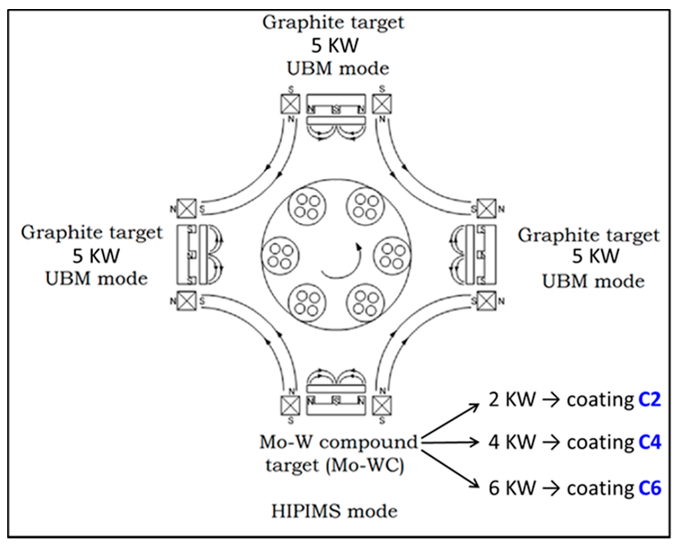
2.1. Mo-W-C Coating Deposition

Mo-W-C coatings were deposited in a combined UBMS + HIPIMS mode, using a 4-target Hauzer HTC 1000-4 PVD coating machine located at Sheffield Hallam University, as shown in Figure 1. During coating deposition, the compound metallic target was activated in HIPIMS mode, whereas the three graphite targets were operated in UBMS mode. The individual power of all three graphite targets was fixed at 5 KW, while the operating power of the compound target was varied at 2, 4 and 6 KW, respectively, in order to deposit three different Mo-W-C coatings, namely C2, C4 and C6. These coatings were deposited at a substrate bias of −65 V and in Ar atmosphere at 250 °C on mirror-polished M2-grade HSS disc samples (quenched and tempered, average hardness of ~740 HV and average Ra ~0.01 μm), which experienced three-fold planetary-gear-type rotation inside the coating chamber. HIPIMS ion etching was used to sputter clean the substrate surfaces before the coating deposition, followed by a thin Mo-W-N base layer deposition in a reactive Ar + N2 atmosphere for minimizing the residual stress and enhancing the overall coating–substrate adhesion. Table 1 details the coating deposition steps for C2, C4 and C6 and related process parameters.

2.2. Coating Characterization

The microstructures and imaging related to the coating properties of C2, C4 and C6 were studied by using an FEI NOVA NANOSEM 200 coupled with an Energy Dispersive X-ray (EDX) module. The elemental composition was examined by using a GD-Profiler 2™ glow discharge optical emission spectroscopy (GDOES) equipped with an RF source, and the depth profiling was performed up to 8 μm from the coating surface. The C/(Mo+W) ratio was calculated from the depth-profile data. An automatic REVETEST scratch tester from CSM instruments was used to assess the critical load (Lc3) for coating delamination, and therefore the adhesion strength between coating and substrate. A cone-shaped (120°) diamond indenter with a preset load of 10 N was allowed to scratch about 10 mm length till the normal force gradually increases to 100 N. The nano-hardness and elastic modulus values were measured by using a CSM nano-indentation tester with a Berkovich diamond indenter. Then 20–25 repetitions with a preset load of 10 mN were carefully performed on the coating surfaces in order to avoid any rough surface features that can impact the result. The resultant load–displacement curves were used to calculate the hardness and modulus values, using the Oliver and Pharr method, and then their average was plotted. The associated software measured both the hardness and modulus values in GPa unit, but later the hardness values were converted to Vickers units (HV).
The tribological behavior in boundary lubricated condition was studied by using CSM pin-on-disc tribometer at both ambient temperature condition (~30 °C and relative humidity of ~30%) and at 200 °C. The lubricant was Mobil1 Extended lifeTM 10 W-60 engine oil. It has a flashpoint of 234 °C and contains both anti-wear (AW) and sulfide-based extreme pressure (EP) additives, but no friction modifiers (i.e., MoDTC) [25]. Therefore the friction behavior in this work is not influenced due to the presence of MoDTC as previously reported for several metal-doped DLC coatings [14,15,16,17]. The sliding tests were performed under 5 N static load against uncoated 100Cr6 steel balls (average hardness of ~260 HV) of 6 mm diameter. The sliding distances were fixed to 7500 m for ambient temperature tests and 1800 m for 200 °C tests. The coefficient of friction was calculated as   μ = F T / F N , where FT and FN are tangential and normal forces in N, respectively. The wear-track profiles were scanned by a DEKTAK 150 surface profilometer, and the respective wear coefficients were calculated via Archard’s equation:   K C = V / F N × d , where V and d are the wear volume (m3) and sliding distance (m), respectively.
The Raman spectra were collected by using a Horiba-Jobin-Yvon HR800 integrated Raman spectrometer equipped with a green laser (of 532 nm wavelength): (i) as-deposited coatings; and (ii) random and selected positions from the tribolayer adhered to the wear tracks, as well as the steel counterparts. For each test condition, the spectra were collected in the range of 50–2250 cm−1, with 5 repetitions and the average was plotted. The background of each spectrum was corrected using a 2nd order polynomial followed by deconvolution and identification of respective Raman peaks via multi-peak Gaussian-fitting function. Apart from the deconvoluted peaks related to the as-deposited coatings and their tribological properties, no other fitted peaks were discussed in this study. These fitted Raman peaks were named A1A5, B1B6 and C1C6 for as-deposited C2, C4 and C6 respectively. When these peak positions were changed as a result of sliding, they were denoted with a ‘dash’ (such as A2′, B3′, C5′, etc.) in the respective Raman spectra collected either from the wear tracks or from the counterpart surfaces. To differentiate the peak positions of the adhered tribolayer from the coatings, the fitted peaks were named as P1P4 and a ‘dash’ was added to each to denote the respective peak shifting as mentioned before. More details on the choices of background correction, fitting functions and spectrum analysis have been described elsewhere [26].

3. Results

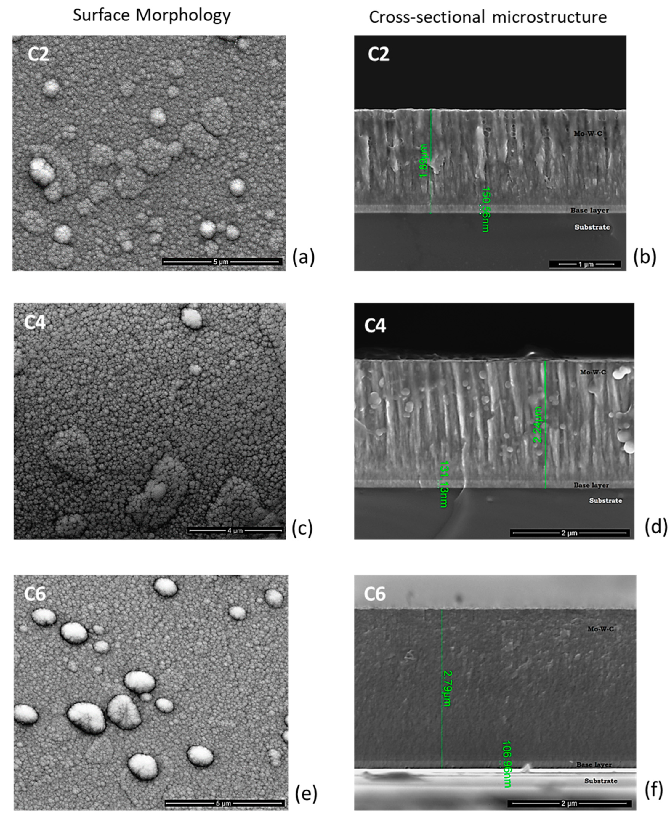
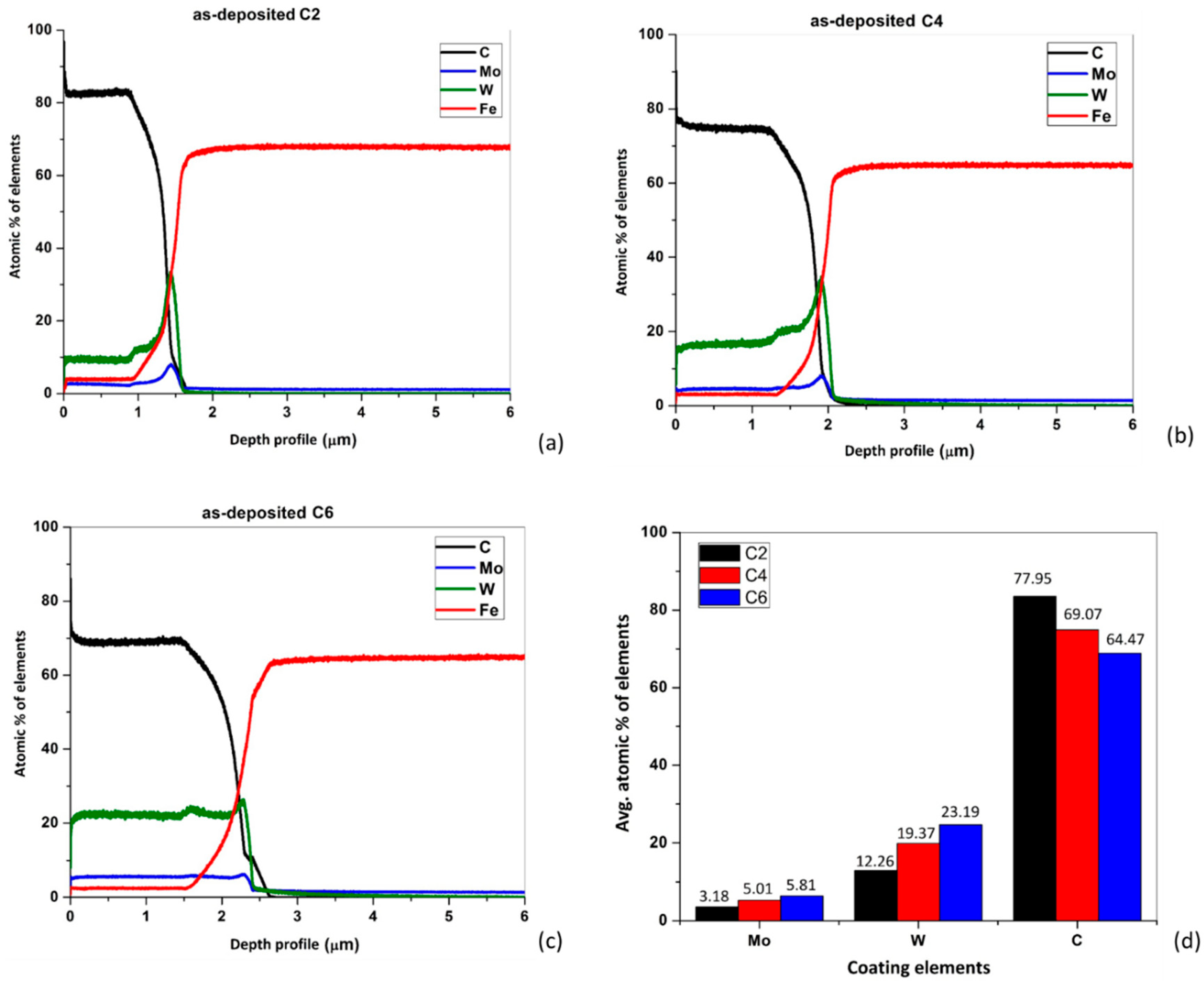
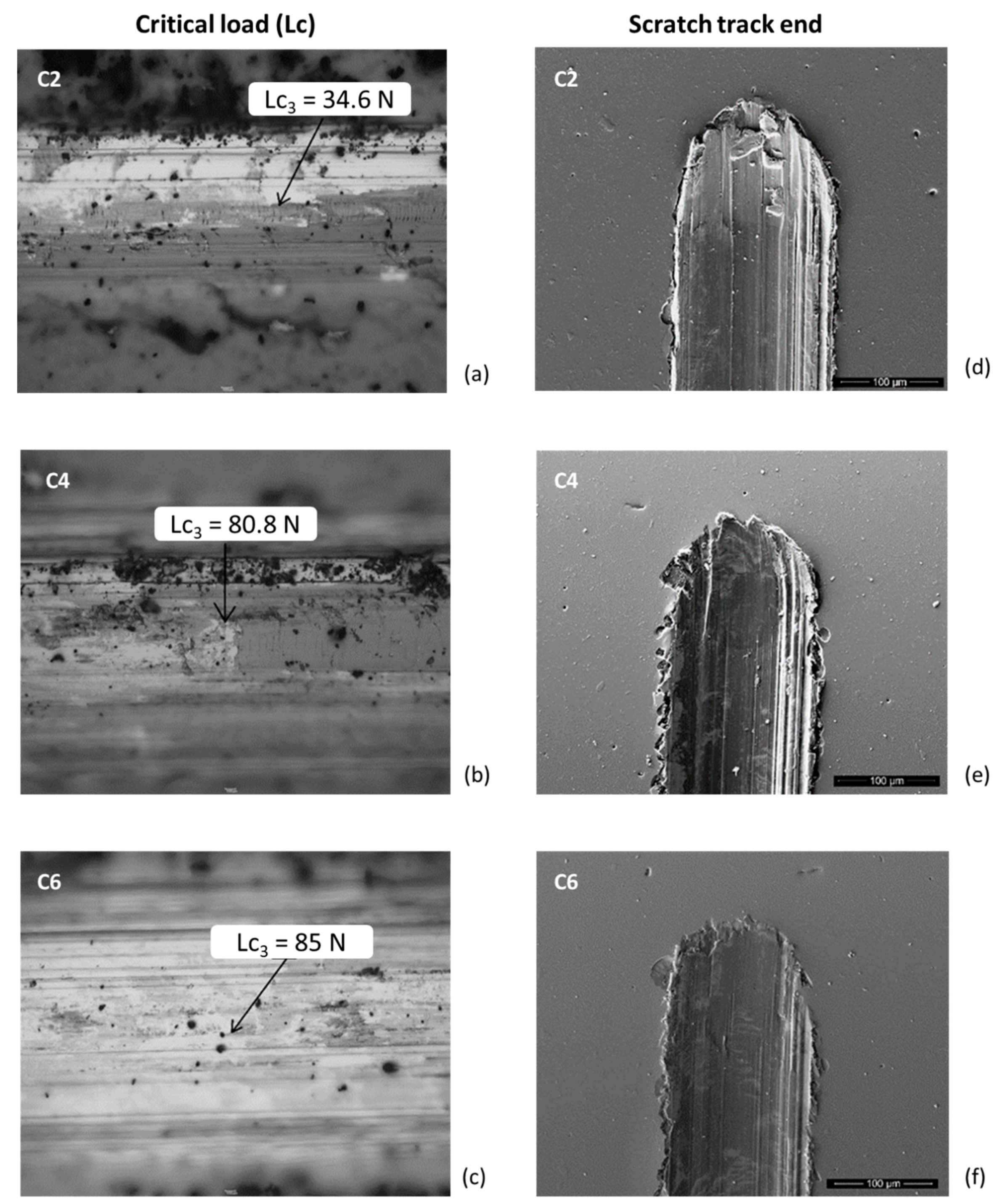
3.1. Coating Microstructure and Composition

Figure 2 shows the surface morphology, cross-sectional microstructure and coating thickness of C2, C4 and C6. The nucleation during the coating growth resulted in little spherical grains with a few tens of nm diameter. Competitive growth of these small grains led to the formation of large grains of few μm diameter as observed in Figure 2a,c,e. The cross-sectional micrographs (Figure 2b,d,f) revealed the coating architecture consisting of a thin base layer (in the range of ~107–150 nm), followed by a dense columnar Mo-W-C structure with domed tops. C2 showed fine columnar grains, which then coalesced and formed larger clusters in C4 as a result of increased target power to 4 KW. With a further increase in the target power to 6 KW, the high adatom mobility led to densification of the fine columnar microstructure with no clear detectable column boundaries in C6. The sputtering yield of the compound target was also increased with an increase in the operating power, eventually leading to an increase in coating thickness. The overall coating thickness was observed as ~1.89, ~2.24 and ~2.79 μm for C2, C4 and C6, respectively.
Figure 3 shows the elemental distribution of C2, C4 and C6, as understood from the GDOES analysis. Elements such as C, Mo and W represented the Mo-W-C coating, whereas Fe indicated the steel substrate underneath. During the depth profiling (Figure 3a–c), all three coatings were observed as being mainly carbon-rich (~65–78%), whereas respective base layers were found to be predominantly metal-rich (Mo+W ~40–50%). Figure 3d summarizes the elemental composition of C2, C4 and C6 from the depth-profiling data. As expected, the percentage of individual metal dopants (Mo, W), and therefore the total metallic content (Mo+W), was gradually increased with an increase in the target power from 2 to 6 KW. The Mo+W content was found to be ~15.44%, ~24.38% and ~29% in C2, C4 and C6, respectively, which corresponded to the C/(Mo+W) ratios of 5:1, 2.8:1 and 2.2:1, as detailed in Table 2. It should be noted that C4 and C6 were deposited at two- and three-times higher target power respectively than C2, but the complex sputtering rate of the compound metallic target did not lead to the likewise increase in the Mo+W content. C4 and C6 contained ~1.6 and ~1.9 times higher Mo+W content than C2, thus resulting in relatively low C/(Mo+W) ratios. The SEM images in Figure 2 further confirmed the linear relationship between the increase in coating thickness and Mo+W content. Therefore, a decrease in the C/(Mo+W) ratio indicated an increase in the coating thickness.
Figure 4a–c shows the adhesive strength of C2, C4 and C6 in terms of critical load LC3, and Figure 4d–f shows the condition of respective scratch track ends for 100 N applied load. Once the critical load is reached, the adhesive failure leads to substrate exposure within the scratch track. C2 showed the lowest LC3 (~34.6 N) when compared to C4 and C6 (LC3 of 80.8 and 85 N, respectively), and therefore a decrease in the C/(Mo+W) ratio indicated an increase in the adhesion strength. This high adhesion strength of C4 and C6 was specifically attributed to their high target power during coating deposition. An operating target power in the range of 4–6 KW generated a significant amount of highly energetic metal ions, which replaced the substrate atoms during the ion etching step, followed by thorough bonding between the identical elements across the interface of coating and substrate. This bonding led to a coating growth aligned with the crystal orientations of the substrate over a small area resulting in enhanced adhesion between coating and substrate. A similar alteration of interface structure by the highly energetic metal ions during HIPIMS etching was already reported for Ti-DLC and Cr-DLC coatings deposited via combined UBMS+HIPIMS mode on the steel substrates [27]. No flaking or interfacial spallation was observed in the SEM images of the scratch track ends, indicating excellent adhesion strength irrespective of the C/(Mo+W) ratio.
Figure 5 summarizes the nano-hardness and elastic modulus of C2, C4 and C6. A high C/(Mo+W) ratio of C2 led to an average nano-hardness value of ~1335.8 HV, whereas both C4 and C6 showed average nano-hardness values of ~1677.5 and ~1702.4 HV, respectively, due to low C/(Mo+W) ratios. This could be directly linked to the presence of hard carbide phases (WC, W2C and Mo2C) in these coatings [21,28], where C4 and C6 particularly contained more metal carbide phases due to their high Mo+W content and therefore high hardness as compared to C2. Similarly, average elastic modulus values of ~194.5, ~236.2 and ~268.5 GPa were observed for C2, C4 and C6, respectively. This behavior was found to be different from Mo-DLC and W-GLC coatings but similar to the W-DLC coating. For example, a combined RF and mid-frequency DC-sputtered nanocomposite Mo-DLC coating showed no change in hardness properties (~10–11 GPa) but an increase in elastic modulus values (~100–120 GPa) with an increase in Mo content [13]. Magnetron-sputtered W-GLC coatings showed a linear increase of hardness (~8–15 GPa), followed by a gradual decrease with an increase in W content [20]. On the other hand, W-DLC coatings deposited by using combined ion-beam and DC-magnetron-sputtering system showed an increase in both hardness and elastic modulus values (~15–19 GPa and ~170–225 GPa, respectively) with an increase in W content [19]. Mo-W-C coatings showed similar average hardness but higher elastic modulus as compared to the reported W-GLC and W-DLC coatings. Overall, a decrease in C/(Mo+W) ratio led to a linear increase in both average hardness and elastic modulus values of Mo-W-C coatings, while maintaining a steady H/E ratio (~0.06–0.07).

3.2. Friction Behavior during Lubricated Sliding

The most extensively researched coating for enhanced tribological properties during room-temperature lubricated sliding is Cr-DLC. When a combination of different lubricants was attempted to understand the friction performance of hybrid ion beam/unbalanced magnetron-sputtered Cr-DLCs, the mean friction coefficient (µ) of ~0.1 was observed as being almost stable irrespective of the Cr content and different lubricant combinations for 2400 m of sliding distance [29]. Thus, a combined steered cathodic arc/unbalanced magnetron-sputtered Cr/C coating was included in this study to set up a reference for the tribological performance of Mo-W-C coatings. Figure 6 shows the friction behavior of C2, C4 and C6 in lubricated conditions, along with Cr/C coating at ambient temperature. All coatings showed a very short run-in period, followed by an extended steady-state period through which µ remained almost stable. Cr/C coating showed µ~0.12, which was ~2–3 times higher as compared to the Mo−W−C coatings (C2, C4 and C6 showed µ~0.047, ~0.033 and ~0.052, respectively). The low µ of Cr/C coating was attributed to the formation of a little amount of lubricious CrCl3 during sliding [26], whereas Raman spectroscopy was used to investigate the reasons for Mo-W-C coatings and the influence of the C/(Mo+W) ratio on such friction reduction.
Figure 7a–c shows the Raman spectra collected from C2, C4 and C6 in as-deposited condition, and Figure 7d–f shows the same when collected within the wear tracks after lubricated sliding at ambient temperature. After deconvolution of the spectra, the positions of both disordered (D band) and sp2-bonded graphitic carbon (G band) peaks, as well as the calculated ID/IG ratio, are reported in Table 3 for all of the abovementioned conditions. The other deconvoluted Raman peaks are not discussed in this work unless related to the tribological properties (if interested, readers can look into the details of all other Raman peaks here [30]). In Figure 7a–c, an ID/IG ratio of 2.51 clearly indicated the graphitic nature of C2, along with the presence of Mo2C peaks, whereas significantly high Mo+W content of C4 and C6 led to the presence of less sp2 bonded carbon and therefore a reduction in ID/IG ratio (1.96 and 1.85 respectively). Thus, a decrease in the C/(Mo+W) ratio indicated a decrease in the degree of graphitization in the as-deposited coatings. Mo2C peaks were also identified in C4, but could not be clearly observed in C6, due to peak shift towards lower wave number and associated peak broadening effect. When Raman spectra were collected within the wear tracks of these coatings, Figure 7d–f showed the presence of a sharp WS2 peak (apart from Mo2C and WC peaks) and a noticeable increase in the ID/IG ratio (2.69, 2.72 and 2.46 for C2, C4 and C6 respectively). During lubricated sliding, two simultaneous events took place: (i) the high flash temperature at the asperity contacts promoted chemical reactions between the engine oil and coating resulting in an in situ formation of lubricious WS2 within the wear track; and (ii) the sliding increased the carbon–carbon bond disorder in the coatings, leading to the formation of debris of more graphitic in nature (i.e., higher sp2 content), which was represented by the high ID/IG ratio. Both of these events significantly reduced the µ at ambient temperature [23]. It was observed that a high C/(Mo+W) ratio retained the graphitic nature of C2 and formed lubricious WS2 during sliding, whereas low C/(Mo+W) ratios converted both C4 and C6 from their as-deposited condition into a more graphitic state during sliding and simultaneously promoted the WS2 formation, leading to a very low µ.
Figure 8 shows the friction behavior of C2, C4 and C6 in lubricated conditions at 200 °C. C2 showed a µ~0.074 during initial ~270 m run-in distance, followed by a drastic decrease to µ~0.036 for the rest of the steady-state period. C4 showed a µ~0.095 up to ~440 m run-in period, and then a gradual decrease in the friction curve led to µ~0.065. A similar trend was observed for C6, which showed µ~0.087 during initial ~630 m run-in distance, followed by a slight decrease to µ~0.061 for rest of the gradually decreased friction curve. It is important to note that, after the initial run-in period, C2 showed a very stable friction behavior, whereas a gradually decreasing trend was observed in both friction curves of C4 and C6. This indicated a possibility for C4 and C6 providing further reduction in µ as compared to C2 if the sliding tests were continued for significantly large distances. This difference in friction behavior led to an overall µ of ~0.042, ~0.072 and ~0.07 for C2, C4 and C6, respectively, during lubricated sliding at 200 °C. In contrast to ambient-temperature tests, the formed tribolayer at 200 °C was found to be strongly adhered to the steel counterparts than the wear track of the coatings.
Figure 9 collates the SEM images of the tribolayer adhered to the steel counterparts of C2, C4 and C6 after lubricated sliding at 200 °C. For all three counterparts, the first SEM image shows the complete view of the wear scar on the ball surface, followed by two high magnification images of the adhered debris, which clearly point out positions ‘a’ and ‘b’ and their respective elemental composition via EDX analysis. Positon ‘a’ indicates the debris smearing over the ball surface, and position ‘b’ shows the debris being accumulated and thickened beside position ‘a’. As observed from Figure 9a, the EDX spectra collected from both positions ‘a’ and ‘b’ of C2 counterpart contained Fe, Cr, C, W, Mo and S peaks. The Fe and Cr peaks were from the steel counterpart, whereas C peak could belong to both the coating and counterpart or to any of either. Specifically, W, Mo and S peaks indicated the formation of a tribolayer on the counterpart surface, where W and Mo came from the coating itself. In contrast to the C2 counterpart, a significant difference in the EDX spectra was observed when collected from the debris positions ‘a’ and ‘b’ for both C4 and C6 counterparts (Figure 9b,c, respectively). The EDX spectrum of position ‘a’ showed strong Fe, Cr and C peaks and weak W, Mo and S peaks, whereas only strong peaks of W, Mo and S were found in position ‘b’ indicating a clear difference in the tribolayer composition. This was particularly observed for low C/(Mo+W) ratios, and therefore Raman spectroscopy was used for further investigation.
Figure 10 shows the Raman spectra collected from the abovementioned positions ‘a’ and ‘b’ of the steel counterparts sliding against C2, C4 and C6, respectively, at 200 °C. Each spectrum contains an image of the adhered debris at the inset, and the locations for spectrum collection are encircled. After deconvolution of the spectra, the position of dominant Raman peaks and the calculated ID/IG ratio are reported in Table 3 for all of the abovementioned conditions. The counterpart of C2 established the presence of sharp MoS2 and WS2 peaks at both positions ‘a’ and ‘b’, along with distinct D and G peaks only at position ‘b’ (Figure 10a). The ID/IG ratio was determined to be 2.14, representing the graphitic carbon debris particles within the tribolayer. On the other hand, the counterpart of C4 demonstrated the presence of WS2 peak, along with dominant D and G peaks at position ‘a’, whereas position ‘b’ only contained sharp MoS2 and WS2 peaks (Figure 10b). An ID/IG ratio of 1.41 indicated the presence of amorphous carbon debris particles in the tribolayer. The counterpart of C6 showed Raman peaks almost similar to that of C4 at both positions ‘a’ and ‘b’ (Figure 10c), but with further reduction in ID/IG ratio to 1.3. Thus, the carbon debris particles of the formed tribolayer were more amorphous in nature for C6 than C4. A decrease in the C/(Mo+W) ratio showed conversion of graphitic-carbon debris into amorphous phase as a result of abrasion during sliding, but exhibited no significant influence on the MoS2 and WS2 phase formation. It should be noted that Mo peak was observed in the EDX spectra at position ‘a’ of both counterparts of C4 and C6; however, the presence of the MoS2 peak was not detected via Raman analyses probably because of its tiny amount at the collection location.
The findings of EDX and Raman analyses together showed the tribolayer composition on the counterpart surface at 200 °C: (i) presence of MoS2, WS2 and graphitic carbon debris particles when sliding against C2; and (ii) presence of MoS2, WS2 and amorphous carbon debris particles when sliding against both C4 and C6. The MoS2 and WS2 phases were in situ formed at the asperity contacts due to the tribo-chemical reactions that occurred between the Mo and W dopants of the coatings and sulfide-based EP additives present in the engine oil during sliding. The rate of these chemical reactions was further promoted at 200 °C, as evident from the high-intensity Raman peaks, and both MoS2 and WS2 played an important role in friction reduction. In addition to this, the severe abrasion during sliding drastically decreased the degree of graphitization of the as-deposited coatings, which further reduced the µ. This was particularly evident for C4 and C6, where graphitic (sp2 bonded) carbons present in the coatings were converted into the amorphous phase during abrasion and therefore led to a significant reduction of µ after the run-in period. A low C/(Mo+W) ratio was found beneficial for these excellent frictional properties at 200 °C, where the reduction in µ was simultaneously influenced by (i) in situ MoS2 and WS2 formation and (ii) conversion of graphitic-carbon-debris particles into the amorphous phase.
The composition of the tribolayer formed at 200 °C was further studied from the debris adhered to the wear track of C2, C4 and C6, as shown in Figure 11. The locations for spectrum collection on the wear track are encircled and shown at the inset of each spectrum. After deconvolution of the spectra, the position of dominant Raman peaks and the calculated ID/IG ratio are reported in Table 3 for all of the abovementioned conditions. The wear track of C2 contained Mo2C phases similar to the as-deposited condition, but the ID/IG ratio of 1.36 indicated a conversion of graphitic carbon particles into the amorphous phase due to severe abrasion during sliding (Figure 11a). This is to note that the debris adhered to the counterpart of C2 retains its graphitic nature (Figure 10a) in contrast to the debris accumulated within the wear track. In contrast to C2, dominant MoS2 and WS2 peaks were observed within the wear tracks of C4 and C6 (Figure 11b,c, respectively). The accumulated debris from the wear tracks of C4 and C6 showed ID/IG ratios of 1.55 and 1.49, respectively, indicating that the wear track contained amorphous carbon-debris particles (Figure 11b,c, respectively) similar to that observed on the counterpart surfaces (Figure 10b,c, respectively). Overall, the tribolayer composition was found identical from coatings with low C/(Mo+W) ratios when collected either from the counterpart surfaces or within the wear tracks. On the other hand, a high C/(Mo+W) ratio led to a noticeably different tribolayer composition within the wear track from the counterpart surface due to severe abrasion of the coating. The influence of this tribolayer on the wear behavior of C2, C4 and C6 was further studied and is reported in the next section.

3.3. Wear Behavior during Lubricated Sliding

Figure 12 shows the wear-track profiles of C2, C4 and C6 after lubricated sliding at ambient temperature with reference to the Cr/C coating. A large and deep wear track was observed for Cr/C coating with a wear coefficient of 9.62 × 10⁻¹⁷ m3N−1m−1 after 5000 m of sliding distance. However, C2, C4 and C6 showed very shallow wear tracks (supported by the associated images) with negligible wear even after 7500 m of sliding distance. As a result, no visible wear scars or any adhered debris were detected on the steel counterparts. This excellent wear resistance was attributed to the combined doping of Mo and W, as compared to the single Cr doping in a carbon-based coating. However, the C/(Mo+W) ratio showed no significant influence on the wear behavior during sliding at ambient temperature.
Figure 13 shows the wear-track profiles of C2, C4 and C6 after lubricated sliding at 200 °C. During the run-in period, the abrasive wear between the coating and the steel counterpart led to the formation of amorphous carbon debris, which was strongly adhered to the counterpart surface rather than the coating. These hard particles continuously exposed new sliding surfaces due to abrasion, resulting in a deep and wide wear track on the coating and similarly large wear scar on the counterpart surface. During the steady-state period, the formation of lubricious MoS2 and WS2 phases in the tribolayer provided necessary protection to the coating from completely being worn out as a result of abrasive wear. The average wear track depth was found ~1.37, ~1.72 and ~1.88 µm for C2, C4 and C6, respectively, and the SEM images showed the track width in the range of ~219–283 µm. The wear-track depths were observed less than their respective coating thicknesses (as shown in Figure 2), which confirmed that the substrate remained unexposed even after a sliding distance of 1800 m at 200 °C. This led to wear coefficients of coatings in the range of ~0.92–1.11 × 10⁻¹⁵ m3N−1m−1. On the other hand, the wear coefficients of the steel counterparts were found in the range of ~3.44–10.8 × 10⁻¹³ m3N−1m−1 (as detailed in Table 3), with respective SEM images already shown in Figure 9. Severe abrasion during sliding led to the largest wear scar on the counterpart of C2, whereas formation of a higher amount of lubricious MoS2 and WS2 phases protected the counterparts of C4 and C6 in comparison. Overall, the abrasion of the steel counterparts was observed significantly higher than the coatings at 200 °C, in contrast to the sliding at ambient temperature.

4. Discussion

The C/(Mo+W) ratio is a key to understand the microstructural characteristics of Mo-W-C coatings, which in turn influences the tribological behavior irrespective of the test conditions. As-deposited C2 contains a high C/(Mo+W) ratio of 5:1, whereas both C4 and C6 maintain low C/(Mo+W) ratios of 2.8:1 and 2.2:1, respectively (see Table 2). Raman analysis of these as-deposited coatings indicate the existence of both metal carbide phases (WC, W2C and Mo2C) and sp2-bonded carbon content representing their graphitic nature. Higher is the C/(Mo+W) ratio, more sp2 bonded carbon content present in the coating increases the ID/IG ratio. So, a decrease in C/(Mo+W) ratio indicates a decrease in the ID/IG ratio and therefore the degree of graphitization in as-deposited coatings (see Figure 7a–c). This decrease in C/(Mo+W) ratio can be further correlated with an increase in the coating thickness, critical load for adhesion, hardness and elastic modulus values (see Table 3). A low C/(Mo+W) ratio indicates (i) the generation of high metal ion fraction during the ion etching step, which drastically increases the adhesion strength; and (ii) the presence of a significantly high Mo+W percentage, and therefore more hard metal carbide phases formed during coating deposition step, which straightaway increases the thickness, average hardness and elastic modulus of C4 and C6. These microstructural properties benefit the tribological behavior at both ambient temperature and 200 °C during lubricated sliding.
Irrespective of the C/(Mo+W) ratios and the test temperatures, the abrasive wear mechanism is present throughout the sliding distance, whereas tribo-chemical wear mechanism is appeared to be particularly dominant during the steady-state period. These two simultaneous events, depending on the test temperature, influence the friction and wear behavior of Mo-W-C coatings during lubricated sliding:
(i)
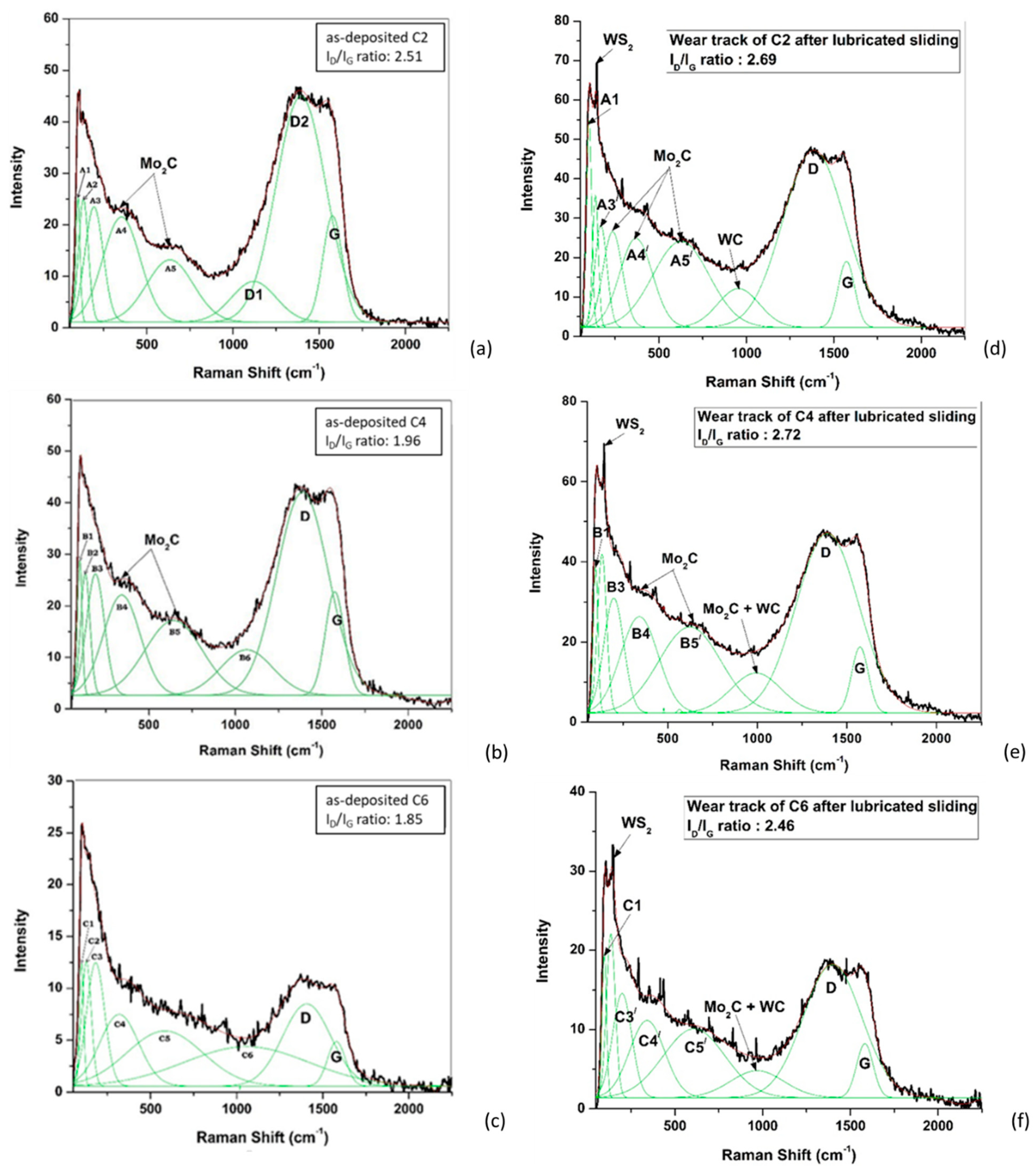
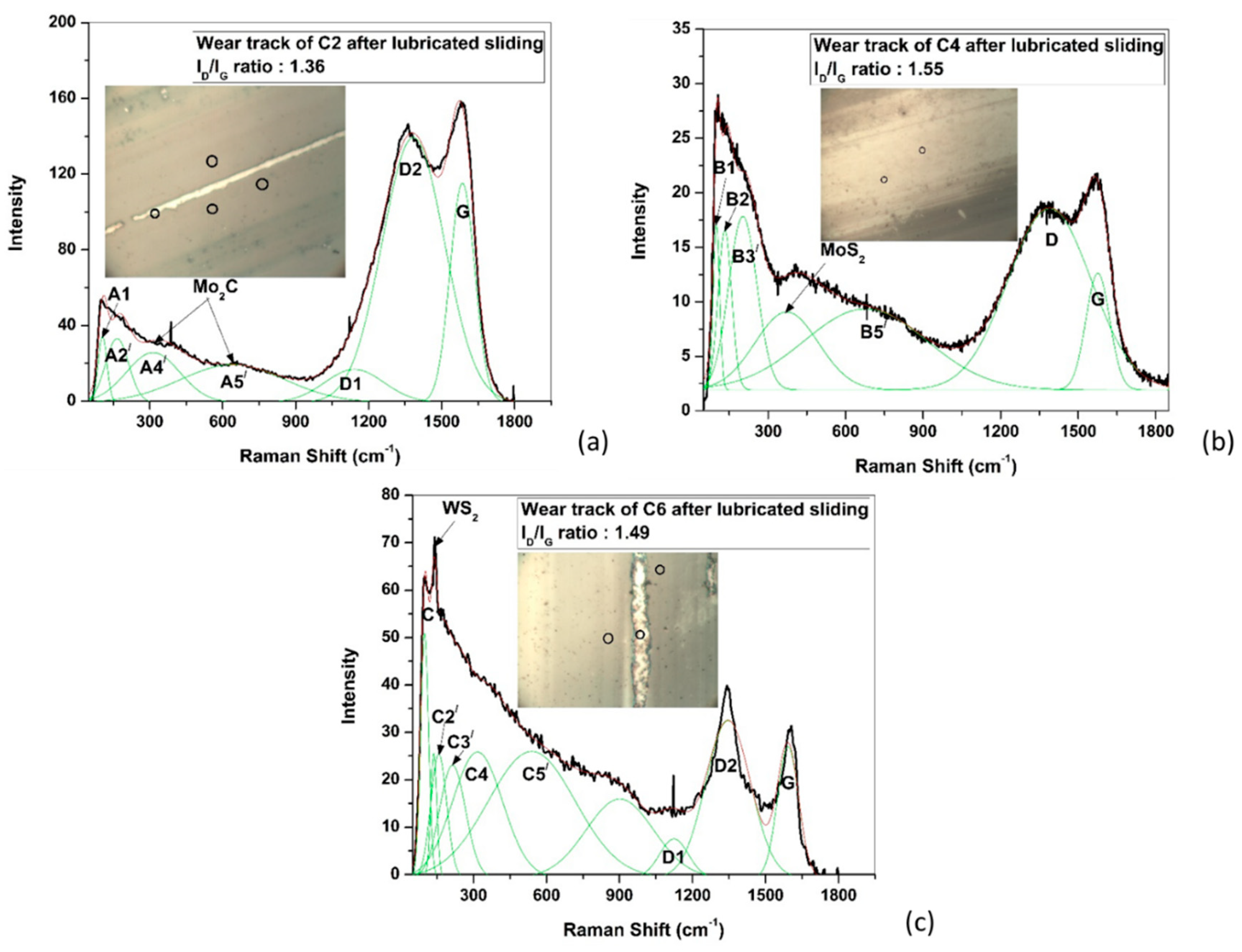
The abrasion dominates the initial run-in period, where the disorder of carbon–carbon bonds in as-deposited coatings is increased due to sliding. At ambient temperature, this disorder leads to decreased graphitic cluster size, which in turn increases the breathing mode of six-fold rings, resulting in high ID/IG ratios. Although the carbon debris particles retain their graphitic nature (Figure 7d–f), maintaining Tuinstra and Koenig (TK) relationship [31], they eventually weaken the material, leading to a very low µ (Figure 6). These rings are further distorted during lubricated sliding at 200 °C, when they open up and form a chain, leading to conversion of graphitic debris particles towards amorphous phase, where TK relationship is no longer valid [31]. This conversion is evident from the significantly low ID/IG ratios (Figure 10 and Figure 11). These amorphous carbon debris particles cause significant wear of the counterparts as compared to the coatings, but eventually helps in achieving friction reduction during steady-state period (Figure 8).
(ii)
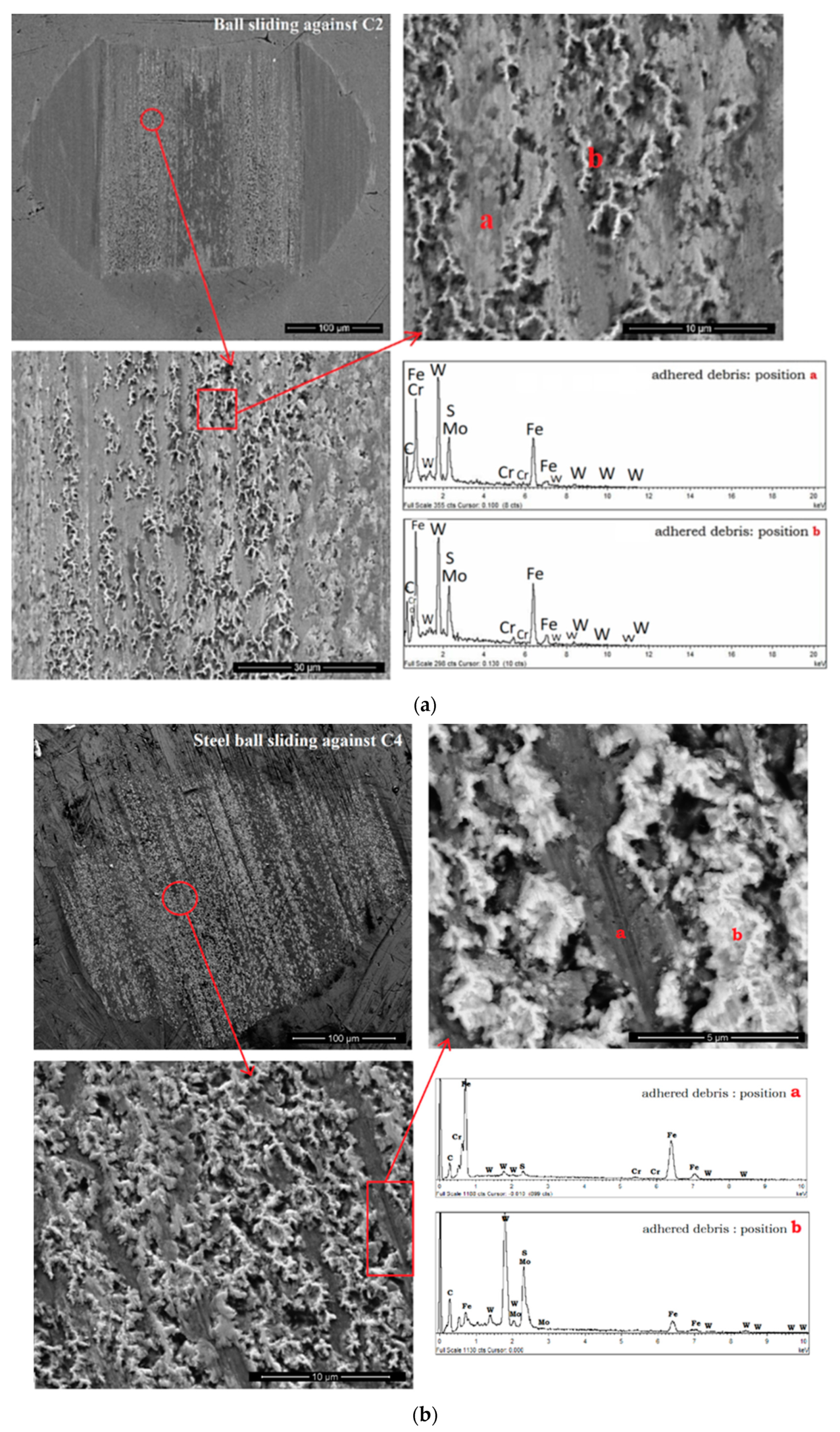
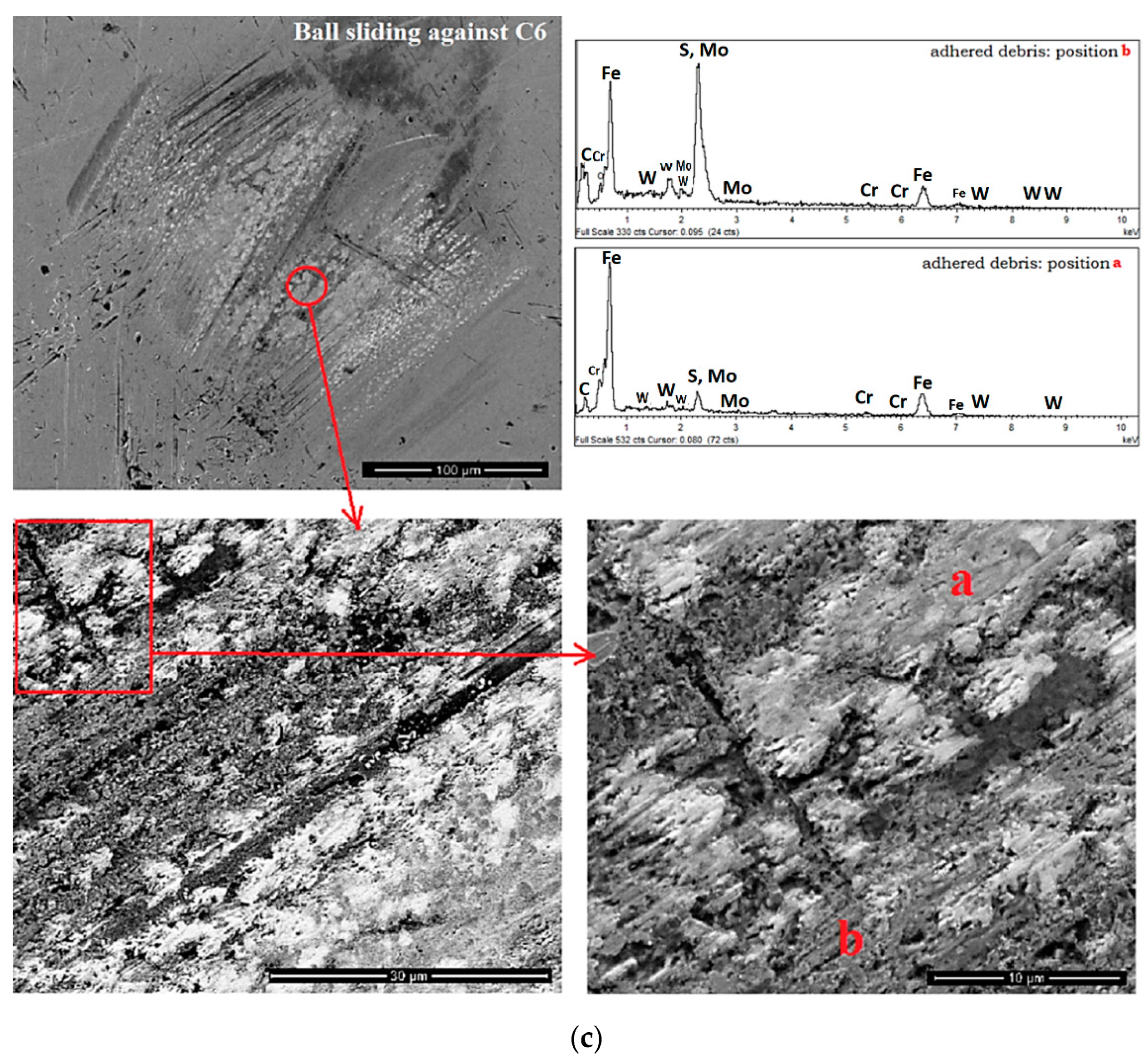
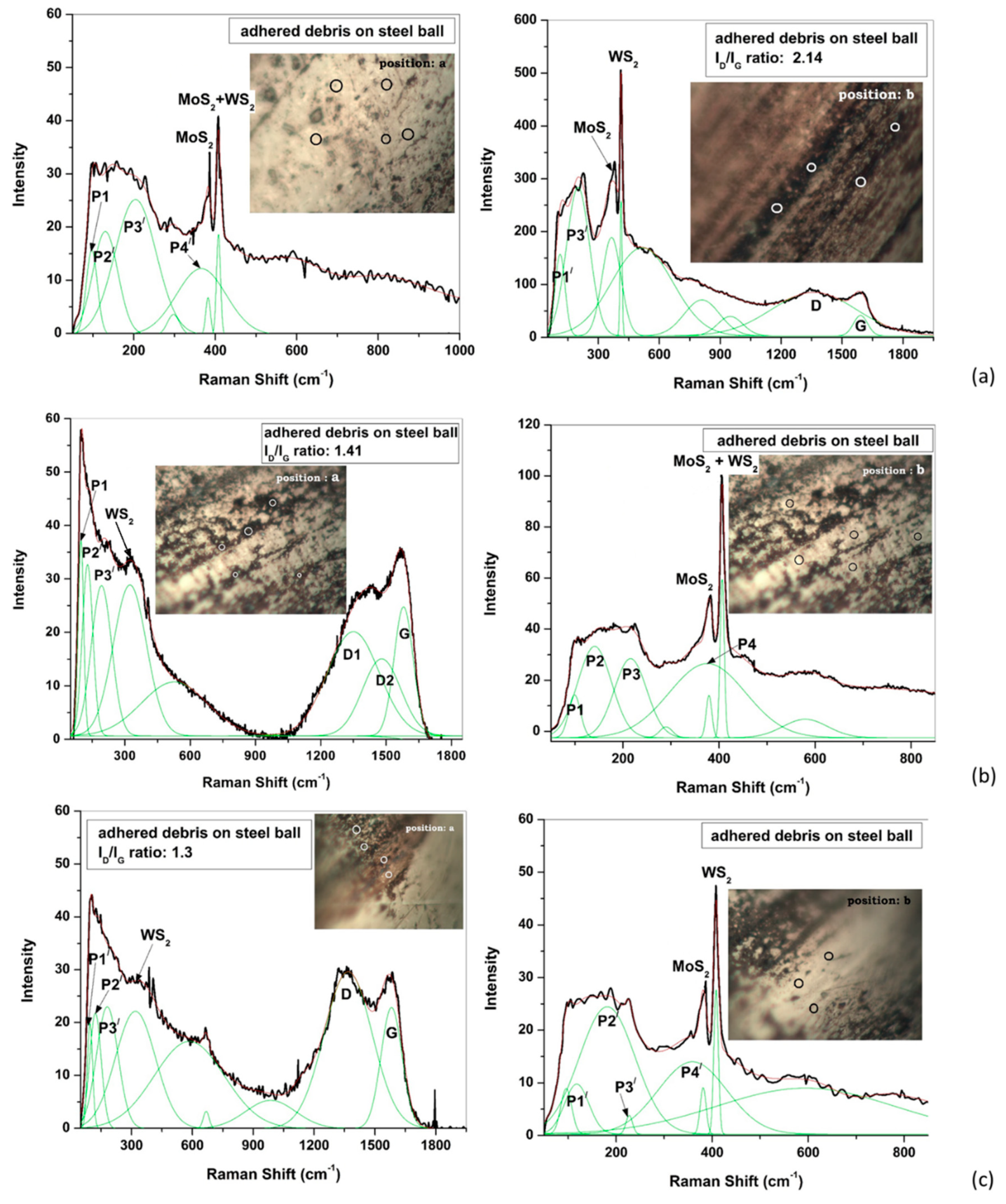
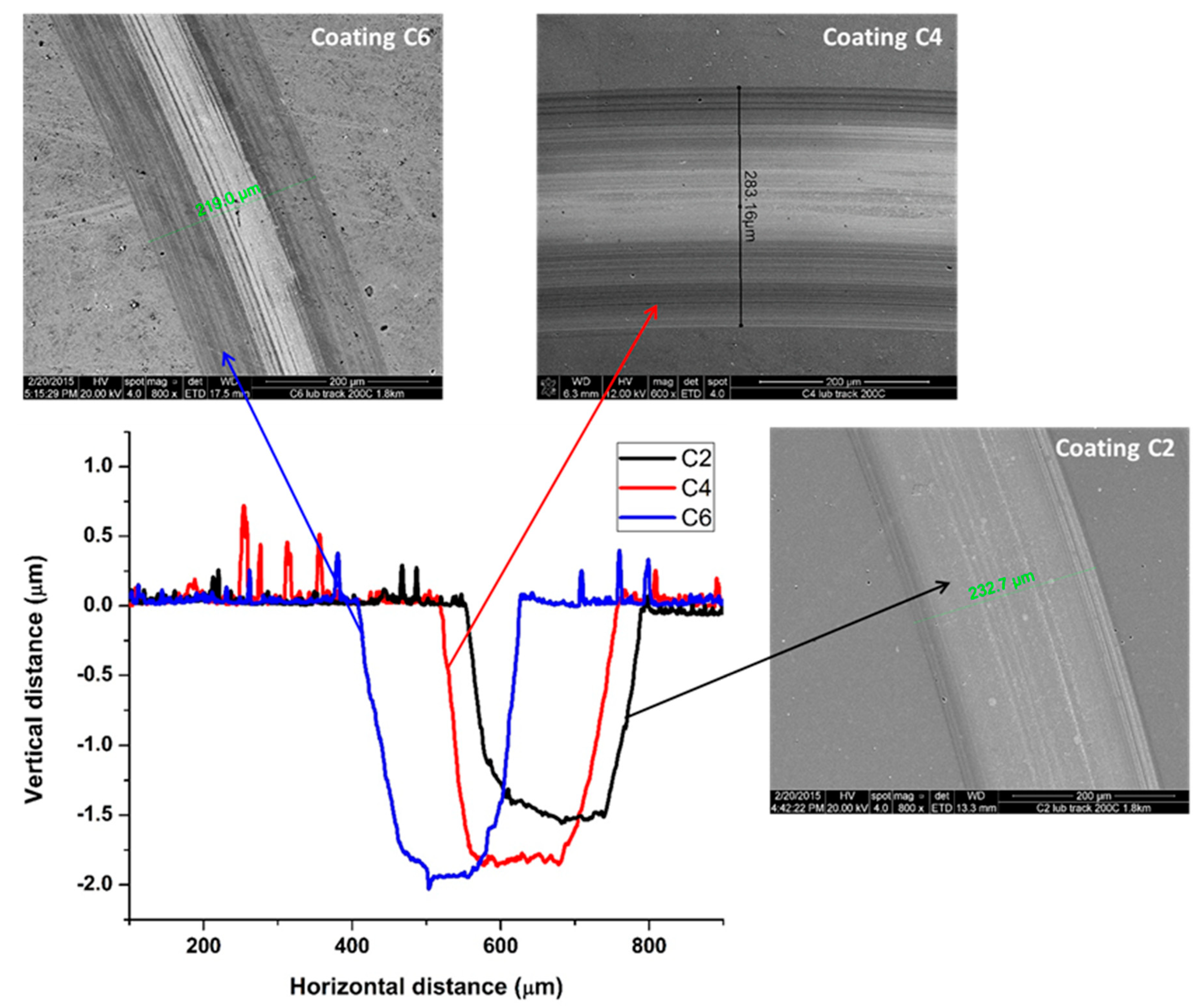
The tribo-chemical reactions take place between both Mo and W dopants of the coatings and the sulfide-based EP additives of the engine oil at the asperity contacts and form an in situ lubricious tribolayer containing MoS2 and WS2. The high flash temperature generated at the asperity contacts promotes these chemical reactions during sliding at ambient temperature, and then it is further accelerated when the test temperature is increased to 200 °C. The formed tribolayer contains mainly WS2 at ambient temperature (evident from Raman spectra in Figure 7d–f), but both MoS2 and WS2 at 200 °C (evident from both the Raman and EDX analyses in Figure 9, Figure 10 and Figure 11). This protective tribolayer leads to negligible wear at ambient temperature (Figure 12) and slightly higher wear at 200 °C (Figure 13), but without any substrate exposure.
These findings indicate that Mo-W-C coatings have outstanding tribological behavior (very low µ~0.033–0.052 and negligible wear of both the coatings and the counterparts) at ambient temperature, and the formed tribolayer contains WS2 and graphitic carbon debris particles. No significant influence of the C/(Mo+W) ratio is observed at ambient temperature. However, low C/(Mo+W) ratios are particularly beneficial to achieve excellent tribological properties at 200 °C. The in situ formation of well-known solid lubricants MoS2 and WS2, along with the presence of amorphous carbon debris particles in the protective tribolayer, are the keys to achieve significantly low µ (~0.042–0.072) during lubricated sliding at 200 °C. This protective tribolayer continuously reduces the µ with an increase in sliding distance (Figure 8) and simultaneously guards the coating from being worn out (Figure 13). It adheres to the counterpart surface (Figure 9) and protects it from high wear. On the other hand, a high C/(Mo+W) ratio does not possess these specific qualities to a similar extent and eventually leads to severe wear of the counterpart surface.

5. Conclusions

The C/(Mo+W) ratios of C2, C4 and C6 are found as 5:1, 2.8:1 and 2.2:1, respectively. This ratio is crucial to describe Mo-W-C coating microstructure and related tribological properties:
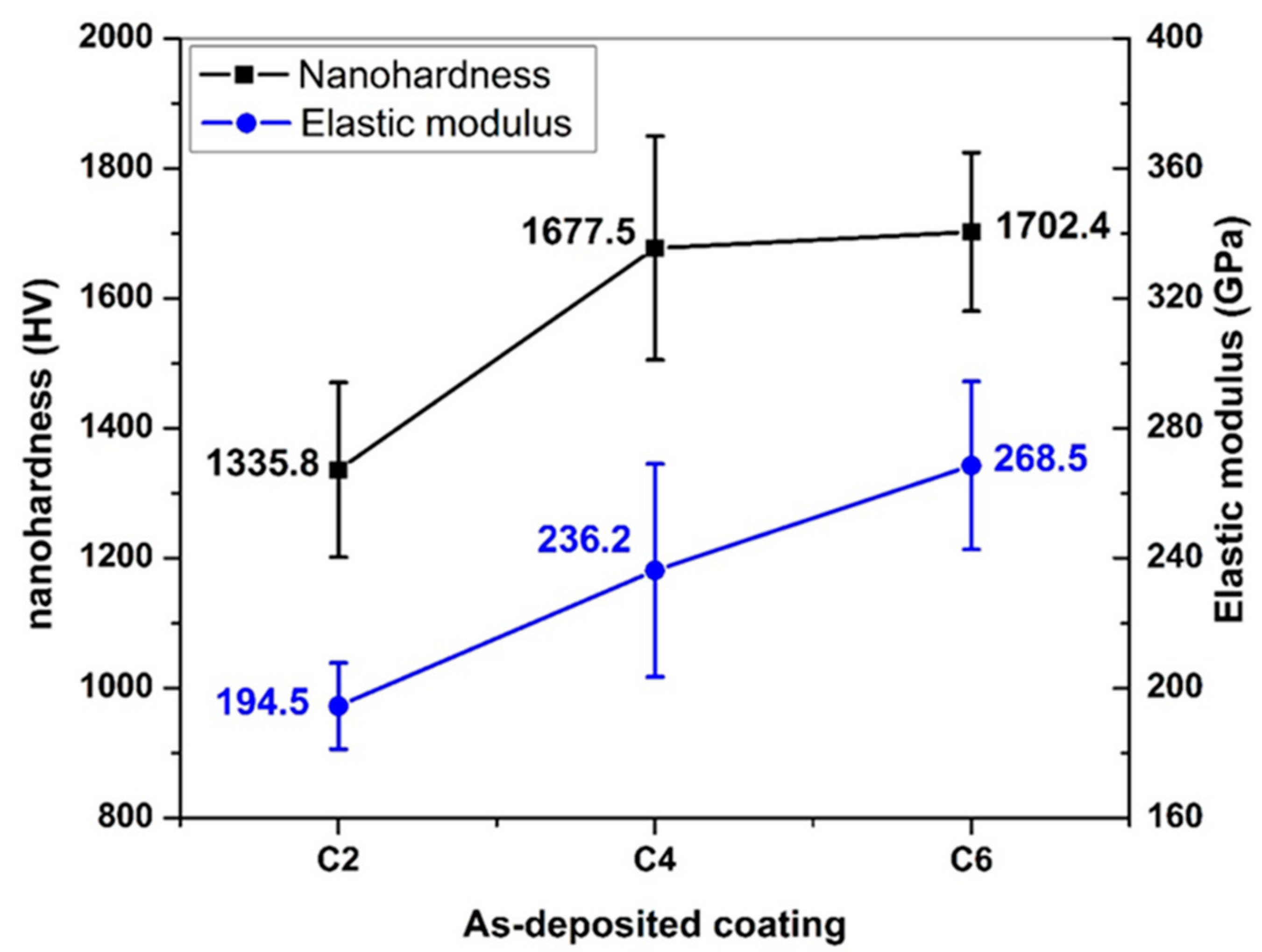
  • A decrease in C/(Mo+W) ratio leads to an increase in coating thickness, adhesion strength, hardness and elastic modulus values but a decrease in the degree of graphitization of as-deposited coatings.
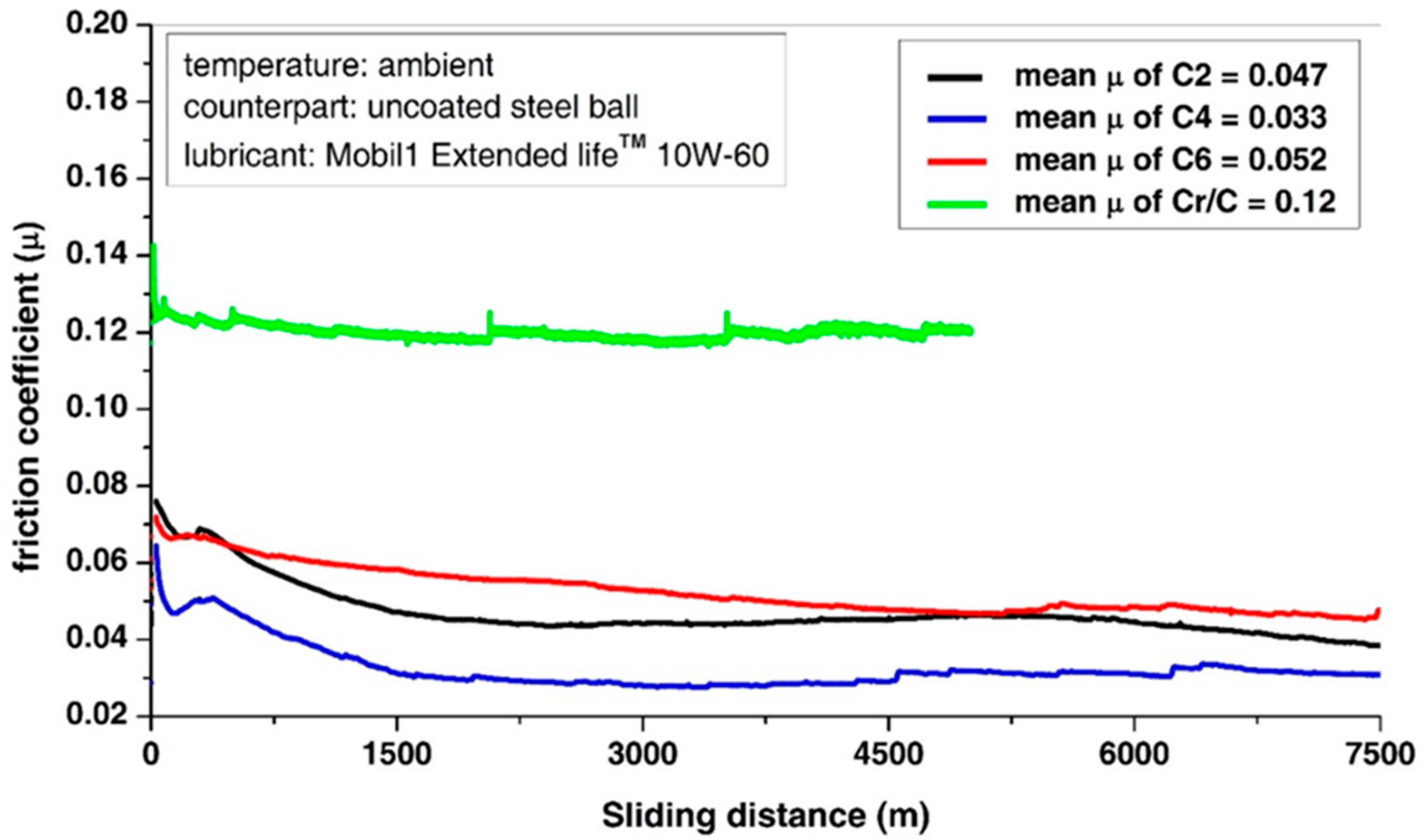
  • Outstanding tribological properties (very low friction and negligible wear) are observed irrespective of the C/(Mo+W) ratio during lubricated sliding at ambient temperature.
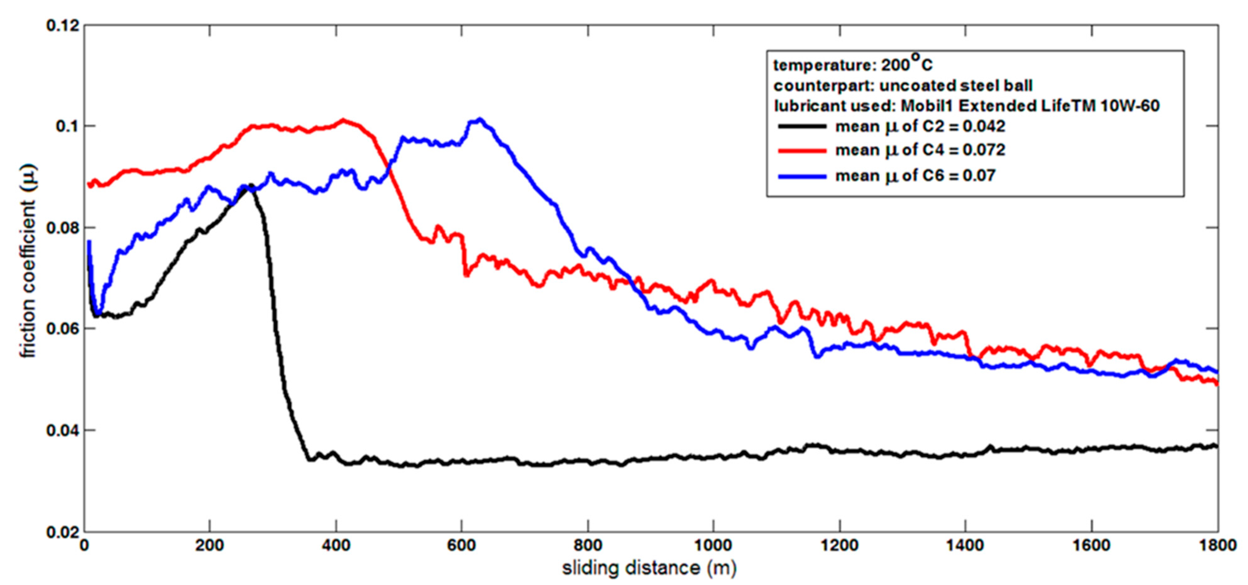
  • Particularly low C/(Mo+W) ratios (2.8:1 and 2.2:1) are observed to be beneficial to achieve excellent tribological properties at 200 °C, and two keys to this are (i) in situ formation of solid lubricants MoS2 and WS2 and (ii) presence of amorphous carbon debris particles in the protective tribolayer. This tribolayer gradually lowers the friction coefficient with an increase in sliding distance by protecting both the coating and counterpart from severe wear. On the other hand, noticeable abrasive wear is observed for a high C/(Mo+W) ratio (5:1) at 200 °C.
  • Abrasive wear mechanism is observed throughout the sliding distance, whereas tribo-chemical wear mechanism is particularly dominant during the steady-state period irrespective of the C/(Mo+W) ratios.

Funding

This research (a part of author’s PhD) was jointly funded by IHI Hauzer Techno Coating BV and Sheffield Hallam University during 2012–2015. After acceptance of the manuscript, the APC was funded by University of Strathclyde, Glasgow.

Institutional Review Board Statement

Not applicable.

Informed Consent Statement

Not applicable.

Data Availability Statement

The experiments and data reported in this manuscript can be found in Author’s PhD thesis ‘Tribological Study of Novel Metal-Doped Carbon-Based Coatings with Enhanced Thermal Stability’ from EThOS (EThOS ID: uk.bl.ethos.741529) or Sheffield Hallam University’s research archive (http://shura.shu.ac.uk/20012/).

Acknowledgments

The work presented in this manuscript was performed as a part of the author’s doctoral (PhD) study at Sheffield Hallam University, UK. The full PhD thesis can be obtained from EThOS (EThOS ID: uk.bl.ethos.741529) or Sheffield Hallam University’s research archive (http://shura.shu.ac.uk/20012/). The author would like to thank IHI Hauzer Techno Coating BV and Sheffield Hallam University, UK, for providing financial support during PhD (2012–2015) and University of Strathclyde, Glasgow for funding the APC.

Conflicts of Interest

The author declares no conflict of interest.

References

  1. Hainsworth, S.V.; Uhure, N.J. Diamond like carbon coatings for tribology: Production techniques, characterisation methods and applications. Int. Mater. Rev. 2007, 52, 153–174. [Google Scholar]
  2. Erdemir, A.; Donnet, C. Tribology of diamond-like carbon films: Recent progress and future prospects. J. Phys. D Appl. Phys. 2006, 38, R301–R316. [Google Scholar] [CrossRef]
  3. Yang, S.; Teer, D.G. Investigation of sputtered carbon and carbon/chromium multi-layered coatings. Surf. Coat. Technol. 2000, 131, 412–416. [Google Scholar] [CrossRef]
  4. Silva, C.W.M.; Branco, J.R.T.; Cavaleiro, A. How can H content influence the tribological behaviour of W-containing DLC coatings. Solid State Sci. 2009, 11, 1778–1782. [Google Scholar]
  5. Erdemir, A. Design criteria for superlubricity in carbon films and related microstructures. Tribol. Int. 2004, 37, 577–583. [Google Scholar]
  6. Wu, W.J.; Pai, T.M.; Hon, M.H. Wear behavior of silicon-containing diamond-like carbon coatings. Diam. Relat. Mater. 1998, 7, 1478–1484. [Google Scholar] [CrossRef]
  7. Zhao, F.; Li, H.; Ji, L.; Wang, Y.; Zhou, H.; Chen, J. Ti-DLC films with superior friction performance. Diam. Relat. Mater. 2010, 19, 342–349. [Google Scholar] [CrossRef]
  8. Ronkainen, H.; Varjus, S.; Holmberg, K. Friction and wear properties in dry, water- and oil-lubricated DLC against alumina and DLC against steel contacts. Wear 1998, 222, 120–128. [Google Scholar]
  9. Ma, G.; Gong, S.; Lin, G.; Zhang, L.; Sun, G. A study of structure and properties of Ti-doped DLC film by reactive magnetron sputtering with ion implantation. Appl. Surf. Sci. 2012, 258, 3045–3050. [Google Scholar] [CrossRef]
  10. Zhang, S.; Sun, D.; Fu, Y.; Du, H. Toughening of hard nanostructural thin films: A critical review. Surf. Coat. Technol. 2005, 198, 2–8. [Google Scholar]
  11. Chang, C.L.; Jao, J.Y.; Chang, T.C.; Ho, W.Y.; Wang, D.Y. Influences of bias voltage on properties of TiAl-doped DLC coatings synthesized by cathodic arc evaporation. Diam. Relat. Mater. 2005, 14, 2126–2131. [Google Scholar] [CrossRef]
  12. Baba, K.; Hatada, R. Preparation and properties of metal-containing diamond-like carbon films by magnetron plasma source ion implantation. Surf. Coat. Technol. 2005, 196, 207–210. [Google Scholar] [CrossRef]
  13. Ji, L.; Li, H.; Zhao, F.; Chen, J.; Zhou, H. Microstructure and mechanical properties of Mo/DLC nanocomposite films. Diam. Relat. Mater. 2008, 17, 1949–1954. [Google Scholar] [CrossRef]
  14. Miyake, S.; Saito, T.; Yasuda, Y.; Okamoto, Y.; Kano, M. Improvement of boundary lubrication properties of diamond-like carbon (DLC) films due to metal addition. Tribol. Int. 2004, 37, 751–761. [Google Scholar] [CrossRef]
  15. Podgornik, B.; Jacobson, S.; Hogmark, S. Influence of EP additive concentration on the tribological behaviour of DLC-coated steel surfaces. Surf. Coat. Technol. 2005, 191, 357–366. [Google Scholar] [CrossRef]
  16. Barros’Bouchet, M.I.D.; Martin, J.M.; Le-Mogne, T.; Vacher, B. Boundary lubrication mechanisms of carbon coatings by MoDTC and ZDDP additives. Tribol. Int. 2005, 38, 257–264. [Google Scholar] [CrossRef]
  17. Liu, K.; Kang, J.-j.; Zhang, G.-a.; Lu, Z.-b.; Yue, W. Effect of temperature and mating pair on tribological properties of DLC and GLC coatings under high pressure lubricated by MoDTC and ZDDP. Friction 2021, 9, 1390–1405. [Google Scholar] [CrossRef]
  18. Fu, R.K.Y.; Mei, Y.F.; Fu, M.Y.; Liu, X.Y.; Chu, P.K. Thermal stability of metal-doped diamond-like carbon fabricated by dual plasma deposition. Diam. Relat. Mater. 2005, 14, 1489–1493. [Google Scholar] [CrossRef]
  19. Yue, W.; Liu, C.; Fu, Z.; Wang, C.; Huang, H.; Liu, J. Effects of Tungsten Doping Contents on Tribological Behaviors of Tungsten-Doped Diamond-Like Carbon Coatings Lubricated by MoDTC. Tribol. Lett. 2015, 58, 1–10. [Google Scholar] [CrossRef]
  20. Yong, Q.; Ma, G.; Wang, H.; Chen, S.; Xu, B. Influence of tungsten content on microstructure and properties of tungsten-doped graphite-like carbon films. J. Mater. Res. 2016, 31, 3766–3776. [Google Scholar] [CrossRef]
  21. Mandal, P.; Ehiasarian, A.P.; Hovsepian, P.E. Tribological behaviour of Mo–W doped carbon-based coating at ambient condition. Tribol. Int. 2015, 90, 135–147. [Google Scholar] [CrossRef] [Green Version]
  22. Mandal, P.; Ehiasarian, A.P.; Hovsepian, P.E. Isothermal and dynamic oxidation behaviour of Mo–W doped carbon-based coating. Appl. Surf. Sci. 2015, 353, 1291–1309. [Google Scholar] [CrossRef] [Green Version]
  23. Hovsepian, P.E.; Mandal, P.; Ehiasarian, A.P.; Sáfrán, G.; Tietema, R.; Doerwald, D. Friction and wear behaviour of Mo–W doped carbon-based coating during boundary lubricated sliding. Appl. Surf. Sci. 2016, 366, 260–274. [Google Scholar] [CrossRef]
  24. Sputter Yield Values; National Physical Laboratory: Teddington, UK, 2014; Available online: http://www.npl.co.uk/science-technology/surface-and-nanoanalysis/services/sputter-yield-values (accessed on 20 September 2021).
  25. Mobil 1 Extended Life 10W-60 Advanced Full Synthetic Engine Oil; ExxonMobil: Irving, TX, USA, 2021; Available online: https://www.mobil.co.uk/en-gb/product/mobil-1-extended-life-10w-60 (accessed on 20 September 2021).
  26. Mandal, P.; Ehiasarian, A.; Hovsepian, P. Lubricated sliding wearmechanism of chromium-doped graphite-like carbon coating. Tribol. Int. 2014, 77, 186–195. [Google Scholar] [CrossRef] [Green Version]
  27. Santiago, J.A.; Fernández-Martínez, I.; Wennberg, A.; Molina-Aldareguia, J.M.; Castillo-Rodríguez, M.; Rojas, T.C.; Sánchez-López, J.C.; González, M.U.; García-Martín, J.M.; Li, H.; et al. Adhesion enhancement of DLC hard coatings by HiPIMS metal ion etching pretreatment. Surf. Coat. Technol. 2018, 349, 787–796. [Google Scholar] [CrossRef]
  28. Sharp, J.; Müller, I.C.; Mandal, P.; Abbas, A.; Nord, M.; Doye, A.; Ehiasarian, A.; Hovsepian, P.; MacLaren, I.; Rainforth, W.M. Characterisation of a High-Power Impulse Magnetron Sputtered C/Mo/Wwear resistant coating by transmission electron microscopy. Surf. Coat. Technol. 2019, 377, 124853. [Google Scholar] [CrossRef]
  29. Sun, J.; Fu, Z.; Zhang, W.; Wang, C.; Yue, W.; Lin, S.; Dai, M. Friction and wear of Cr-doped DLC films under different lubrication conditions. Vacuum 2013, 94, 1–5. [Google Scholar] [CrossRef]
  30. Mandal, P. Tribological Study of Novel Metal-Doped Carbon-Based Coatings with Enhanced Thermal Stability. Ph.D. Thesis, Sheffield Hallam University, Sheffield, UK, May 2015. [Google Scholar]
  31. Ferrari, A.C.; Robertson, J. Interpretation of Raman spectra of disordered and amorphous carbon. Phys. Rev. B 2000, 61, 14095. [Google Scholar] [CrossRef] [Green Version]
Figure 1. Schematic showing deposition of Mo-W-C coatings—C2, C4 and C6.
Applsci 11 10189 g001
Figure 2. Surface morphology and cross-sectional microstructure of (a,b) C2, (c,d) C4 and (e,f) C6.
Applsci 11 10189 g002
Figure 3. Elemental distribution of Mo-W-C coatings detected by GDOES analysis: (a) C2, (b) C4, (c) C6 and (d) summary of elemental composition.
Applsci 11 10189 g003
Figure 4. Adhesion strength of C2, C4 and C6 demonstrating (ac) individual critical load (Lc3) and (df) SEM images of the respective scratch track ends for 100 N applied load.
Applsci 11 10189 g004
Figure 5. Nano-hardness and elastic modulus of C2, C4 and C6.
Applsci 11 10189 g005
Figure 6. Friction behavior of C2, C4 and C6 in lubricated condition at ambient temperature (Cr/C coating is used as a reference).
Applsci 11 10189 g006
Figure 7. Raman spectra collected from C2, C4 and C6 (ac) in as-deposited condition and (df) within the wear tracks after lubricated sliding at ambient temperature.
Applsci 11 10189 g007
Figure 8. Friction behavior of C2, C4 and C6 in lubricated condition against steel balls at 200 °C.
Applsci 11 10189 g008
Figure 9. SEM images (taken at both low and high magnifications) of the tribolayer adhered to the steel counterpart and related EDX analysis on the debris positions ‘a’ and ‘b’ after lubricated sliding against (a) C2, (b) C4 and (c) C6 at 200 °C.
Applsci 11 10189 g009aApplsci 11 10189 g009b
Figure 10. Raman spectra collected from the debris positions ‘a’ and ‘b’ (as mentioned in Figure 9) after lubricated sliding against (a) C2, (b) C4 and (c) C6 at 200 °C.
Applsci 11 10189 g010
Figure 11. Raman spectra collected from the wear tracks of (a) C2, (b) C4 and (c) C6 after lubricated sliding at 200 °C.
Applsci 11 10189 g011
Figure 12. Wear-track profiles of C2, C4 and C6 after lubricated sliding at ambient temperature (Cr/C coating is used as a reference).
Applsci 11 10189 g012
Figure 13. Wear-track profiles of C2, C4 and C6 after lubricated sliding at 200 °C.
Applsci 11 10189 g013
Table 1. Deposition of C2, C4 and C6—process steps and related parameters.
Process StepsProcess Parameters
Chamber Pressure (mbar)Temperature (°C)Other Operational Parameters
Target cleaning2 × 10−3150Graphite targets (UBMS mode, 1–3 KW)
Mo-WC target (HIPIMS mode, 900–1250 V)
HIPIMS Ion etching1 × 10−3150HIPIMS ion etching at 1300 V with 40 min step time
Graphite targets (UBMS mode) OFF
Ar flow rate: 80 sccm
−1200 V substrate bias
Base-layer deposition3.5 × 10−325030 min step time
Ar and N2 flow rate: 200 sccm (each)
−65 V substrate bias
Graphite targets (UBMS mode, 0.5 KW)
Mo-WC target (HIPIMS mode, 1000 V)
Mo-W-C coat-ing deposition3.2 × 10−32504 h step time
Ar flow rate: 250 sccm
−65 V substrate bias
Graphite targets (UBMS mode, 5 KW)
Mo-WC target (HIPIMS mode, 2 KW for C2, 4 KW for C4 and 6 KW for C6)
Table 2. C/(Mo+W) ratio as calculated from GDOES analysis.
CoatingCarbon Content (Atomic %)Total Metallic
Content (Atomic %)
C/(Mo+W)
Ratio
C277.9515.445:1
C469.0724.382.8:1
C664.47292.2:1
Table 3. Influence of C/(Mo+W) ratio on microstructural and tribological properties of Mo-W-C coatings.
Coating PropertiesMo-W-C CoatingsC2C4C6
C/(Mo+W) Ratio5:12.8:12.2:1
Microstructural propertiesCoating thickness (µm)~1.89~2.24~2.79
Critical load Lc3 (N) 34.680.885
Average nano-hardness (HV)1335.81677.51702.4
Average elastic modulus (GPa)194.5236.2268.5
H / E   ratio0.0670.070.062
D peak position (cm−1)1119.6 (D1),
1393.05 (D2)
1387.041406.7
G peak position (cm−1)1576.521574.321579.37
I D / I G   ratio2.511.961.85
Tribological properties at ambient temperatureMean µ~0.047 ~0.033~0.052
D peak position (cm−1)1385.841390.851398.12
G peak position (cm−1)1572.061572.611582.44
I D / I G   ratio2.692.722.46
Wear coefficient Kc
(m3N−1m−1) of coating
negligiblenegligiblenegligible
Wear coefficient Kc
(m3N−1m−1) of counterpart
negligiblenegligiblenegligible
Mean µ (run-in period)~0.074~0.095~0.087
Mean µ (steady-state period)~0.036~0.065~0.061
Mean µ (overall)~0.042~0.072~0.07
Tribological properties at 200 °CMoS2 peak position (cm−1)
of tribolayer on counterpart
382.5 (position ‘a’),
402 (position ‘b’)
379, 408
(position ‘b’)
381 (position ‘b’)
WS2 peak position (cm−1)
of tribolayer on counterpart
412 (position ‘b’)323 (position ‘a’), 406.5 (position ‘b’)319 (position ‘a’), 408 (position ‘b’)
D peak position (cm−1)
of tribolayer on counterpart
1361.331349.53 (D1), 1479.81 (D2)1368.27
G peak position (cm−1)
of tribolayer on counterpart
1591.061580.271582.03
I D / I G   ratio of tribolayer on counterpart2.141.411.3
MoS2 peak position (cm−1)
of tribolayer within wear track
-372-
WS2 peak position (cm−1)
of tribolayer within wear track
--136.5
D peak position (cm−1)
of coating within wear track
1141.05 (D1),
1383.31 (D2)
1389.33 1372.35
G peak position (cm−1)
of coating within wear track
1585.521575.871588.56
I D / I G   ratio of coating within wear track1.361.551.49
Wear coefficient Kc
(m3N−1m−1) of coating
~0.92 × 10⁻¹⁵~1.11 × 10⁻¹⁵~1.02 × 10⁻¹⁵
Wear coefficient Kc
(m3N−1m−1) of counterpart
~10.8 × 10⁻¹³~3.44 × 10⁻¹³~6.17 × 10⁻¹³
Publisher’s Note: MDPI stays neutral with regard to jurisdictional claims in published maps and institutional affiliations.

