
Power Quality Enhancement in a Grid-Integrated Photovoltaic System Using Hybrid Techniques


Abstract
:1. Introduction
2. Literature Review
3. Problem Identification
- The random nature of the solar array generates fluctuations in electric power. These fluctuations harm the stability and power quality of electric power systems.
- Due to the high penetration level of solar energy in distribution systems, the utility (grid) is of high concern, because it provides a threat to the entire system in terms of THD, voltage regulation, and stability.
- To develop an innovative and integrated approach using optimization techniques that enhance the power quality of solar power systems.
- In all conditions, the main purpose of PV with an additional inverter topology is to develop energy savings, along with excellent service. The challenging tasks for this type of system design are:
- An appropriate multilevel inverter topology.
- A control strategy for the PV generator.
4. Objectives
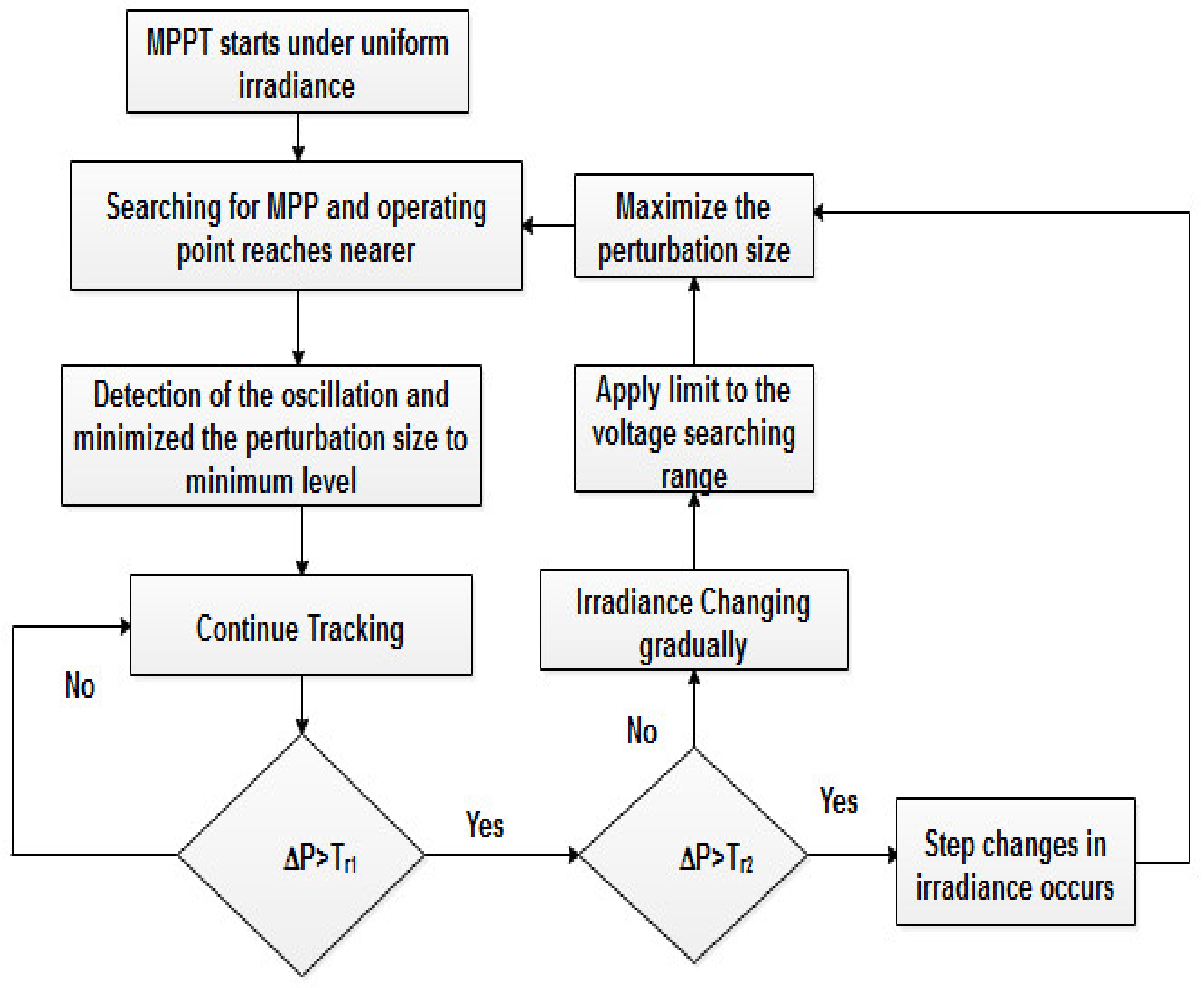
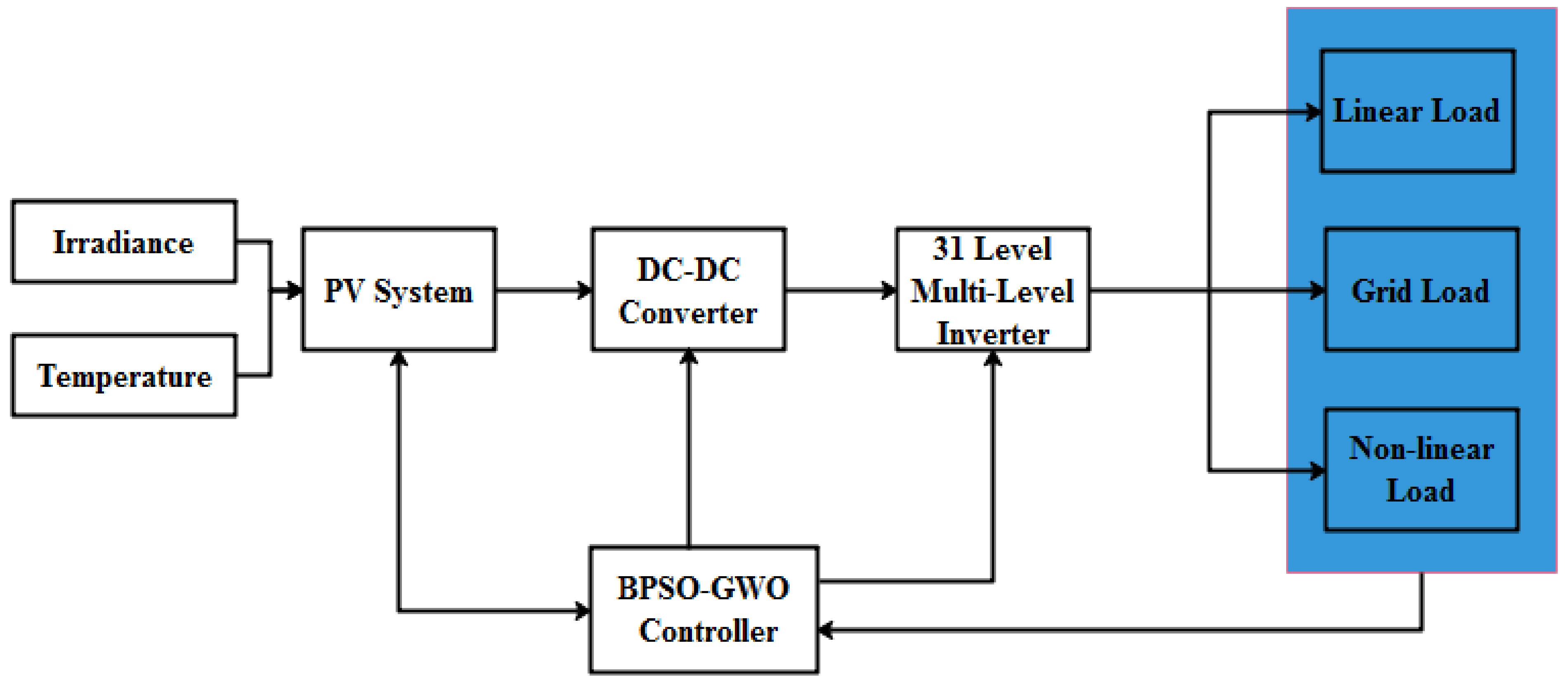
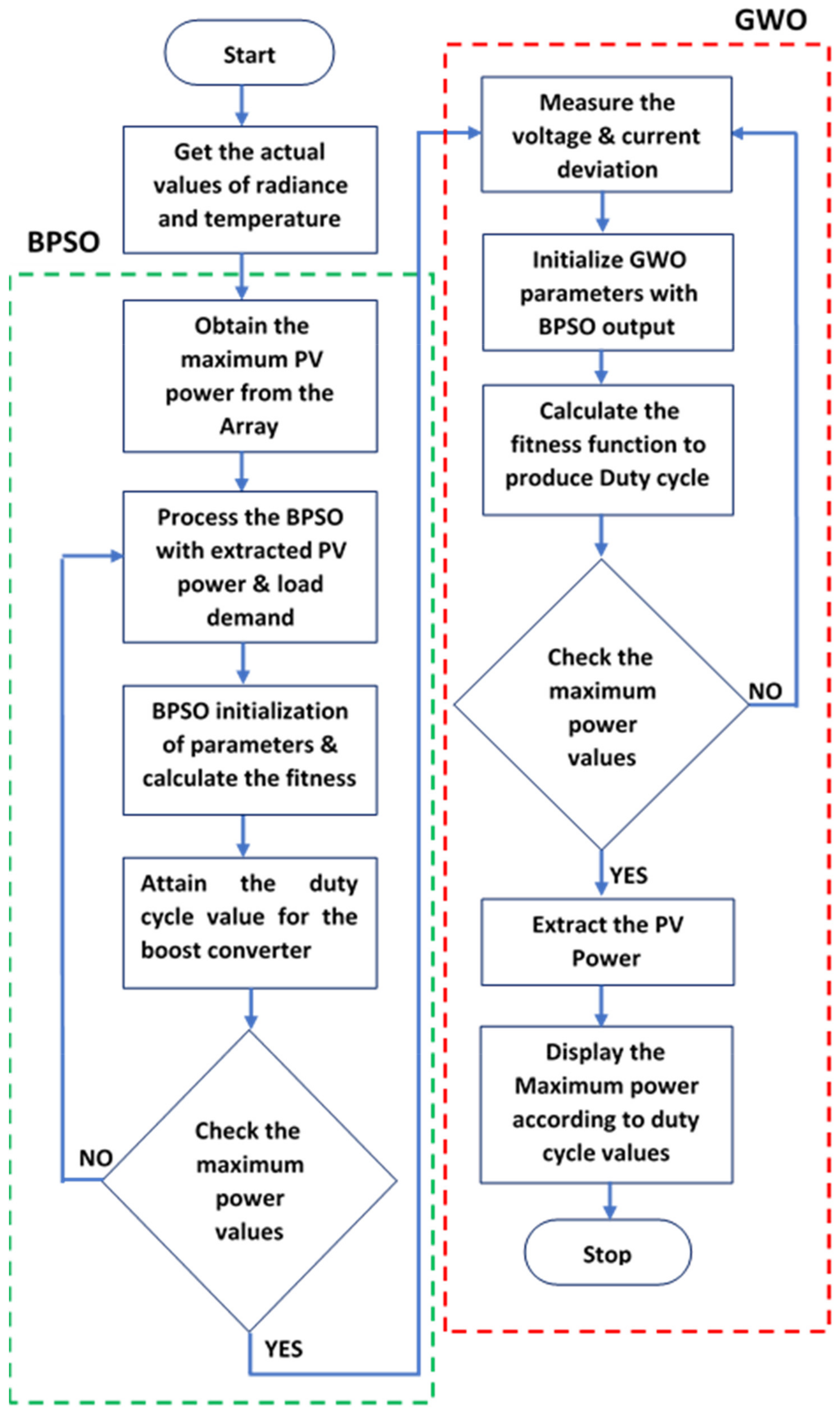
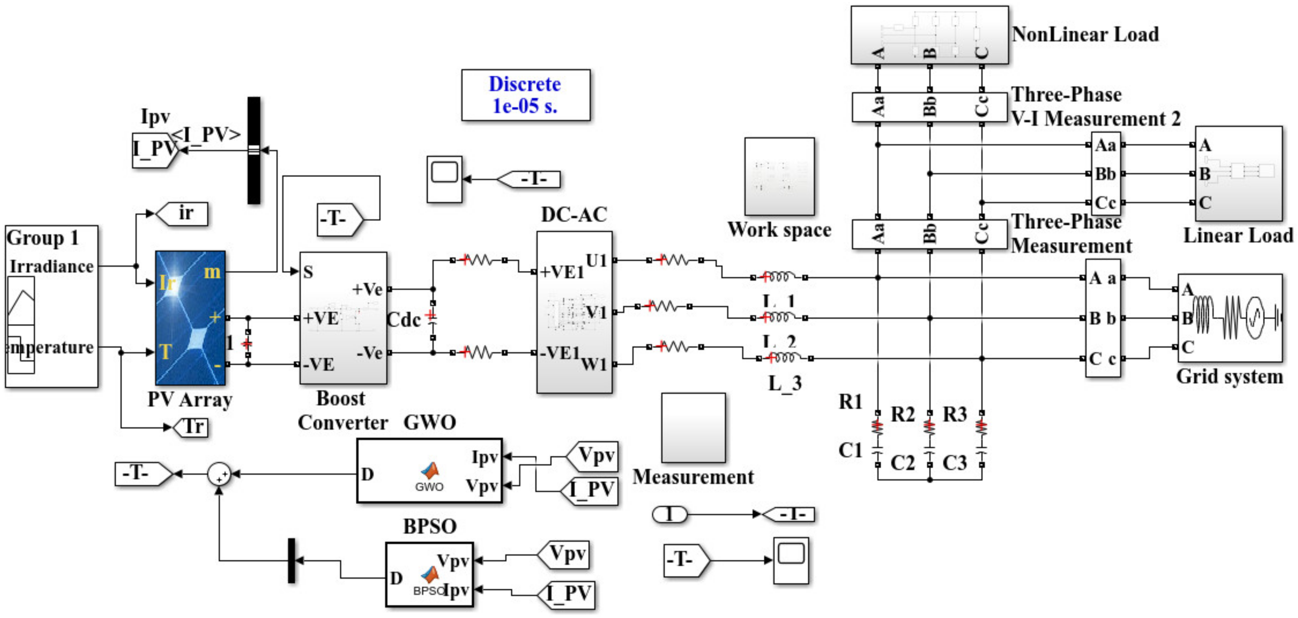
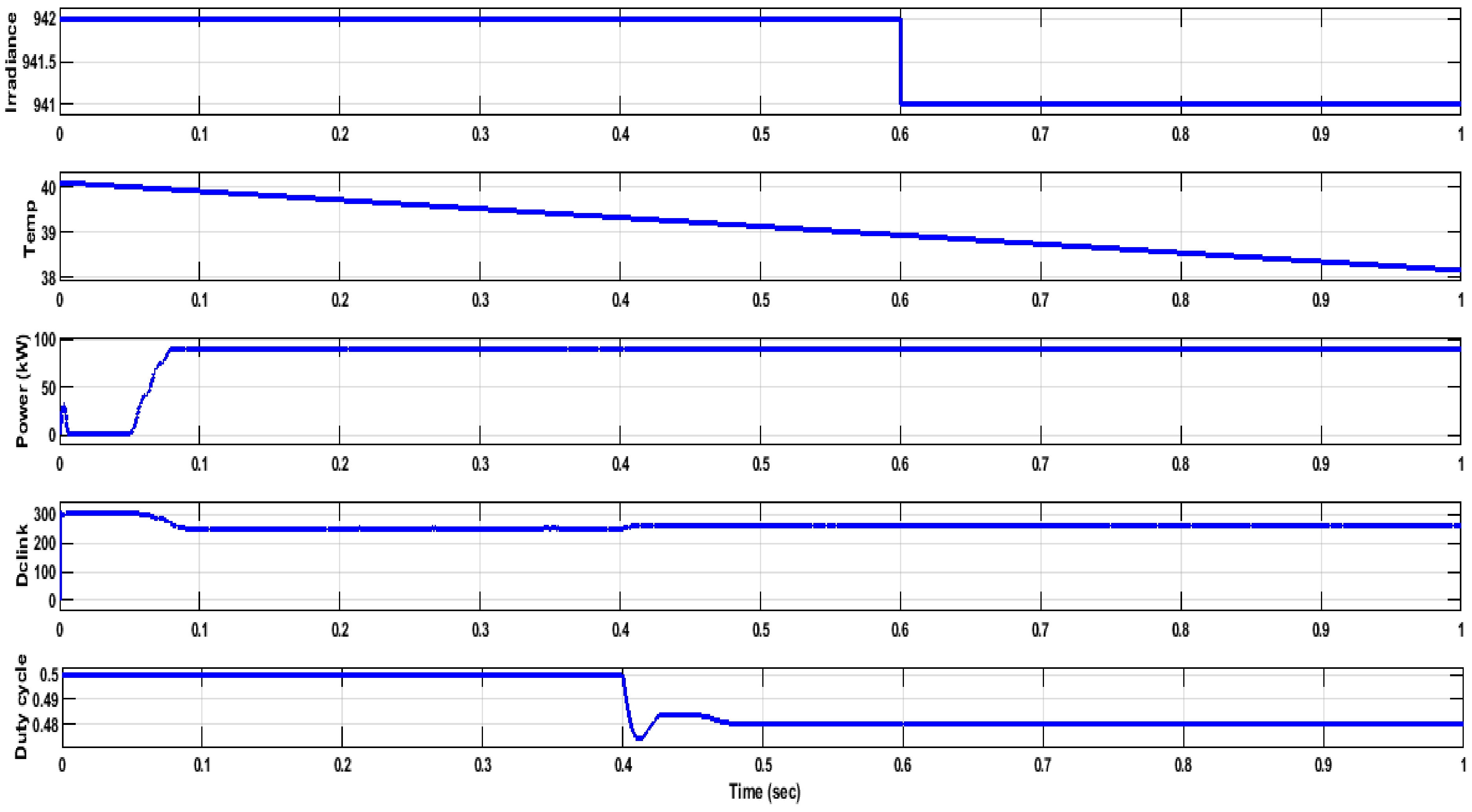
- In this research, a combination of the BPSO and GWO methods with a boost converter is proposed to control the MPPT of the PV array.
- The output of the BPSO–GWO generates the value of the duty cycle (D). In order to achieve a better THD, the value of the duty cycle should be adjusted accordingly.
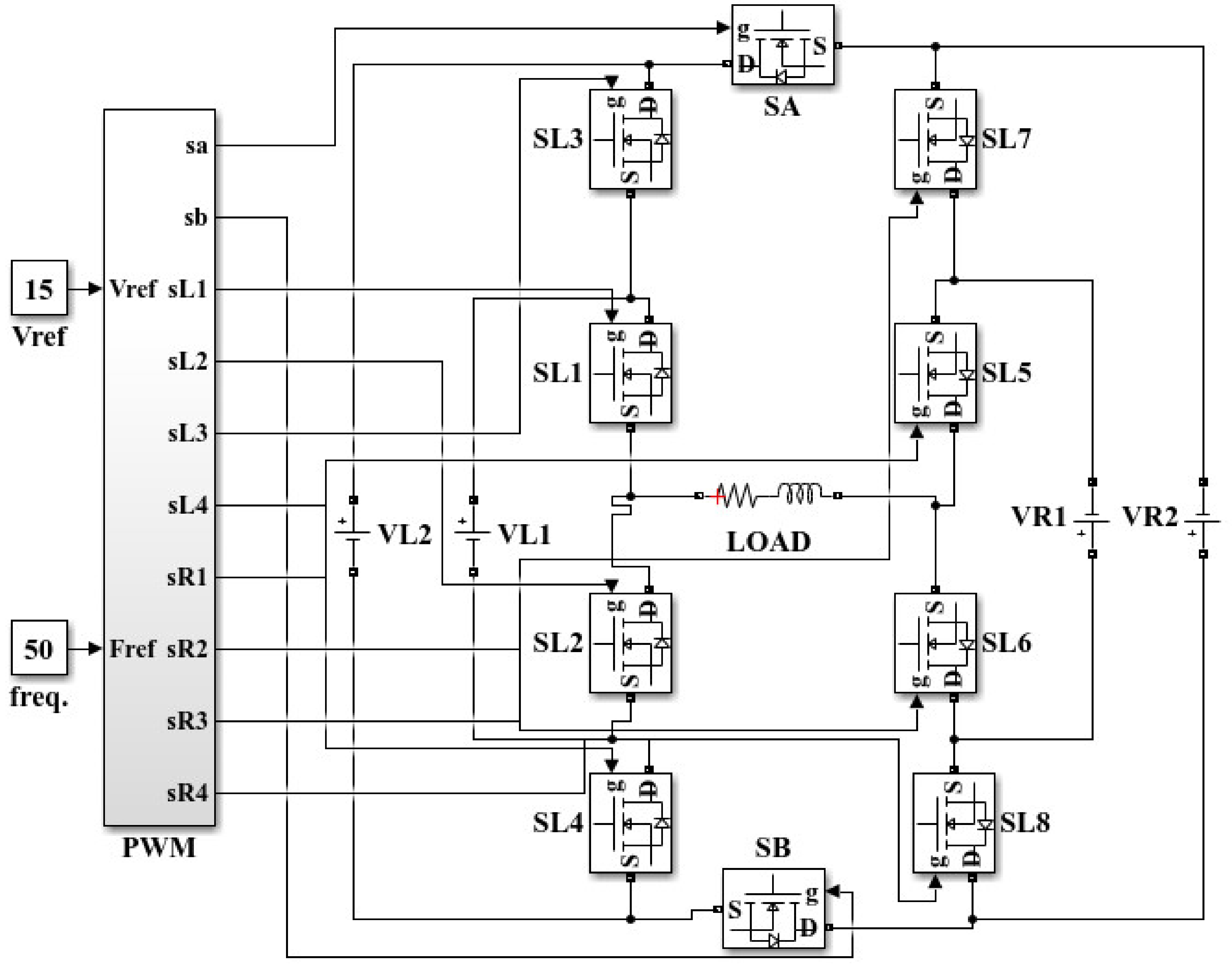
- To design a 31-level multilevel inverter for the PV system. Similarly, PWM pulses are produced from the control algorithm, which are given to the multilevel inverter.
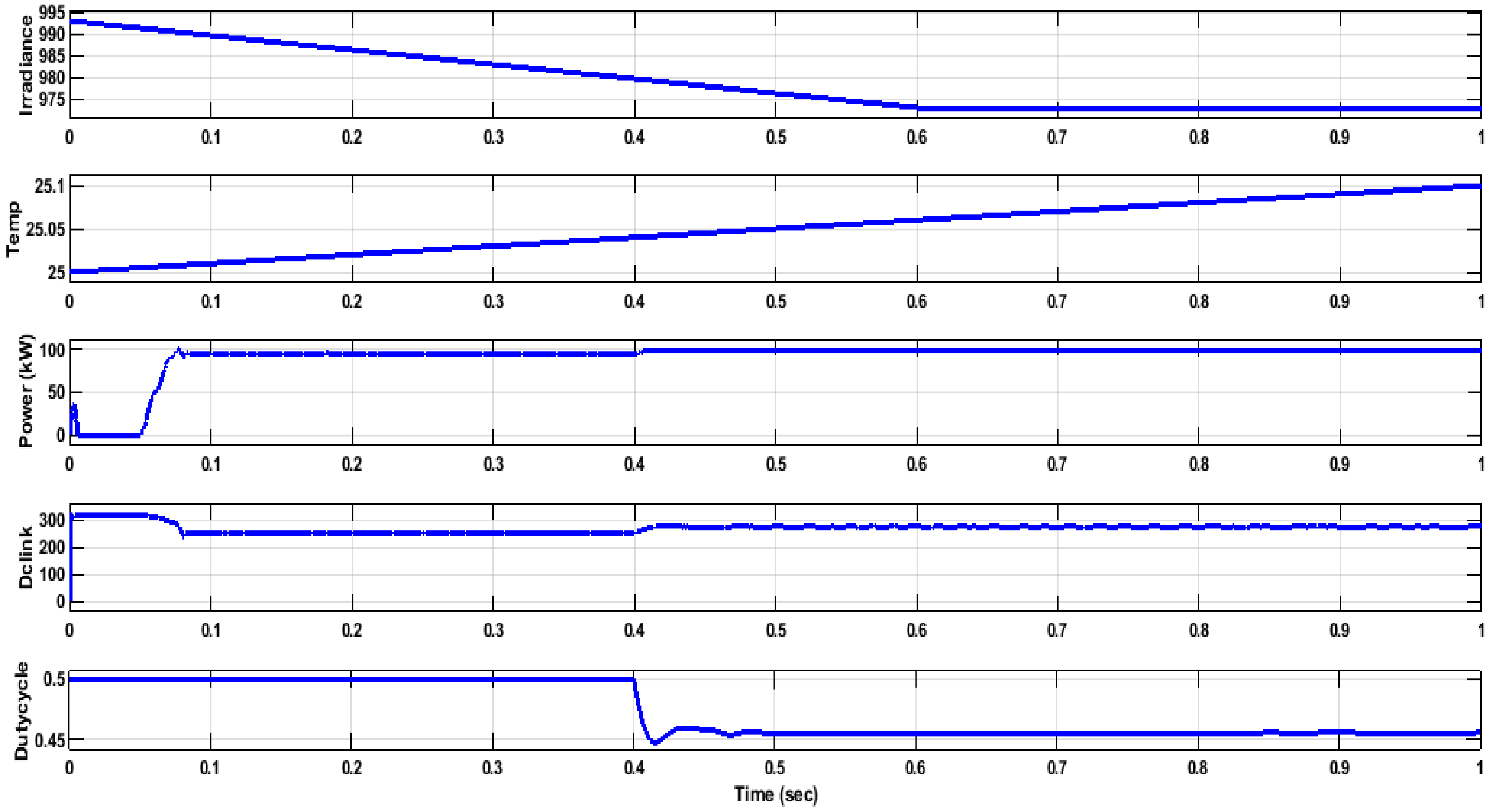
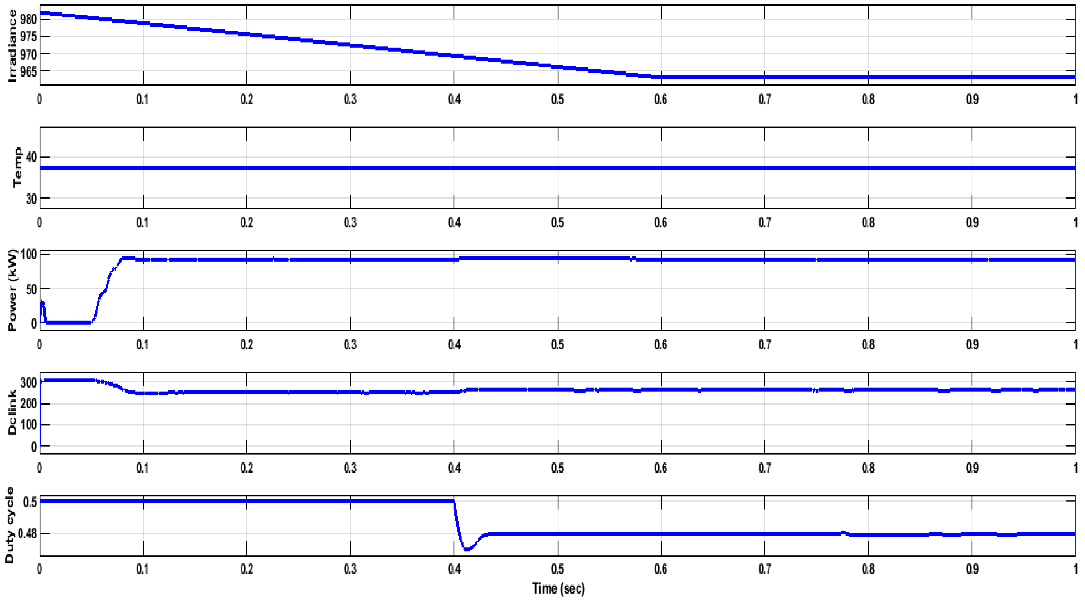
- To analyze the capability of MPPT tracking and the efficiency of the inverter at different irradiation conditions, a hybrid combination of BPSO and GWO is proposed.
5. Modeling of the PV Array
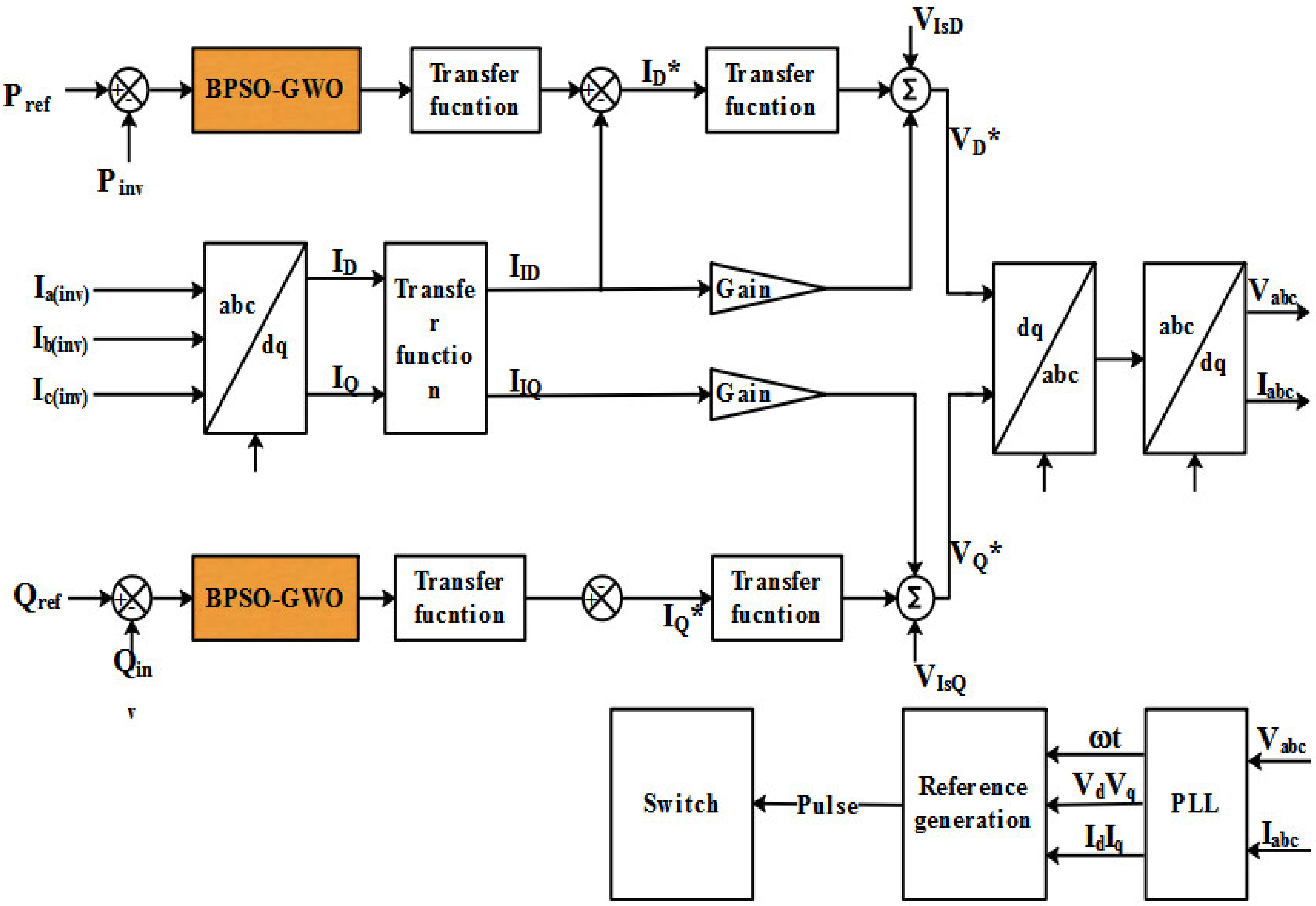
6. Proposed Method
6.1. 31-Level Multi-Level Inverter
6.2. Preliminaries
6.3. Binary Particle Swarm Optimization
6.4. Grey Wolf Optimization
- a.
- Encircling prey
- b.
- Hunting
Fitness Function Derivation
7. Results and Discussion
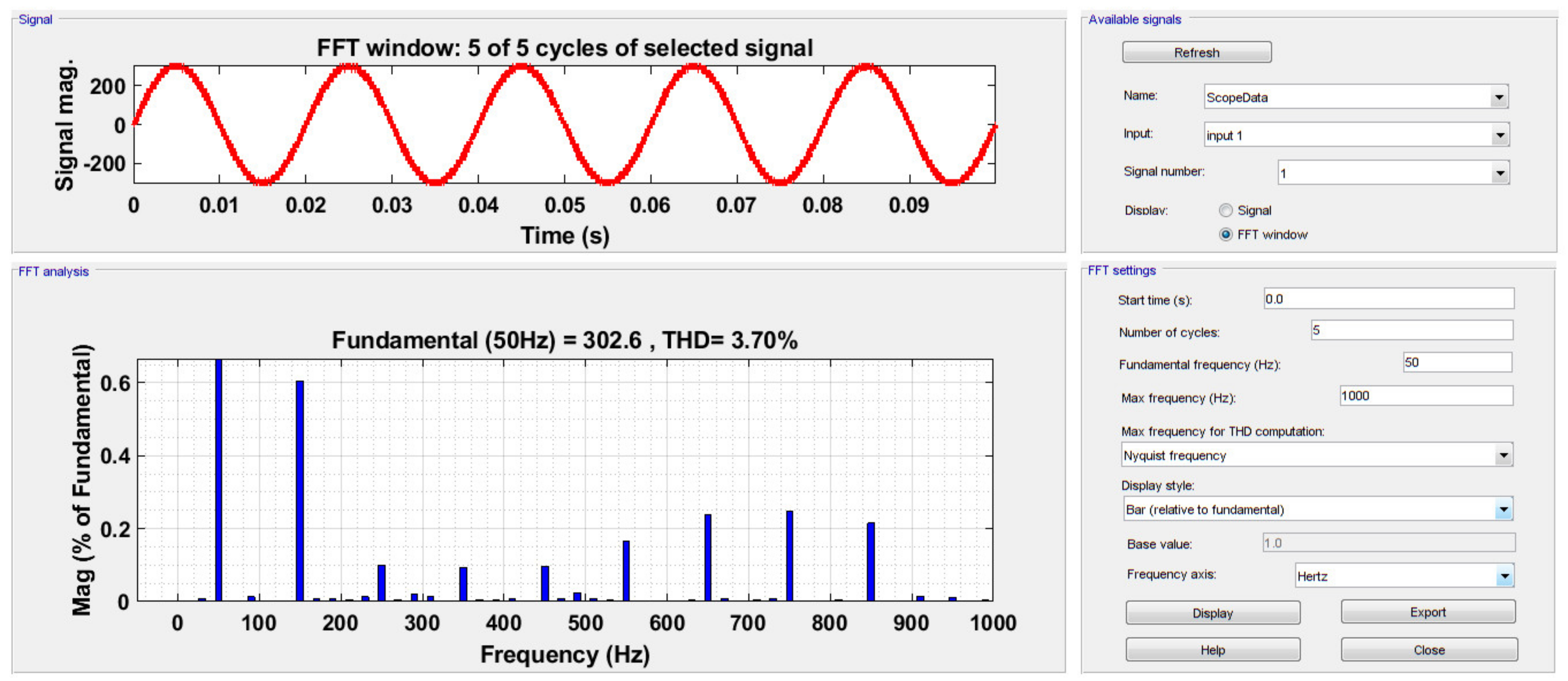
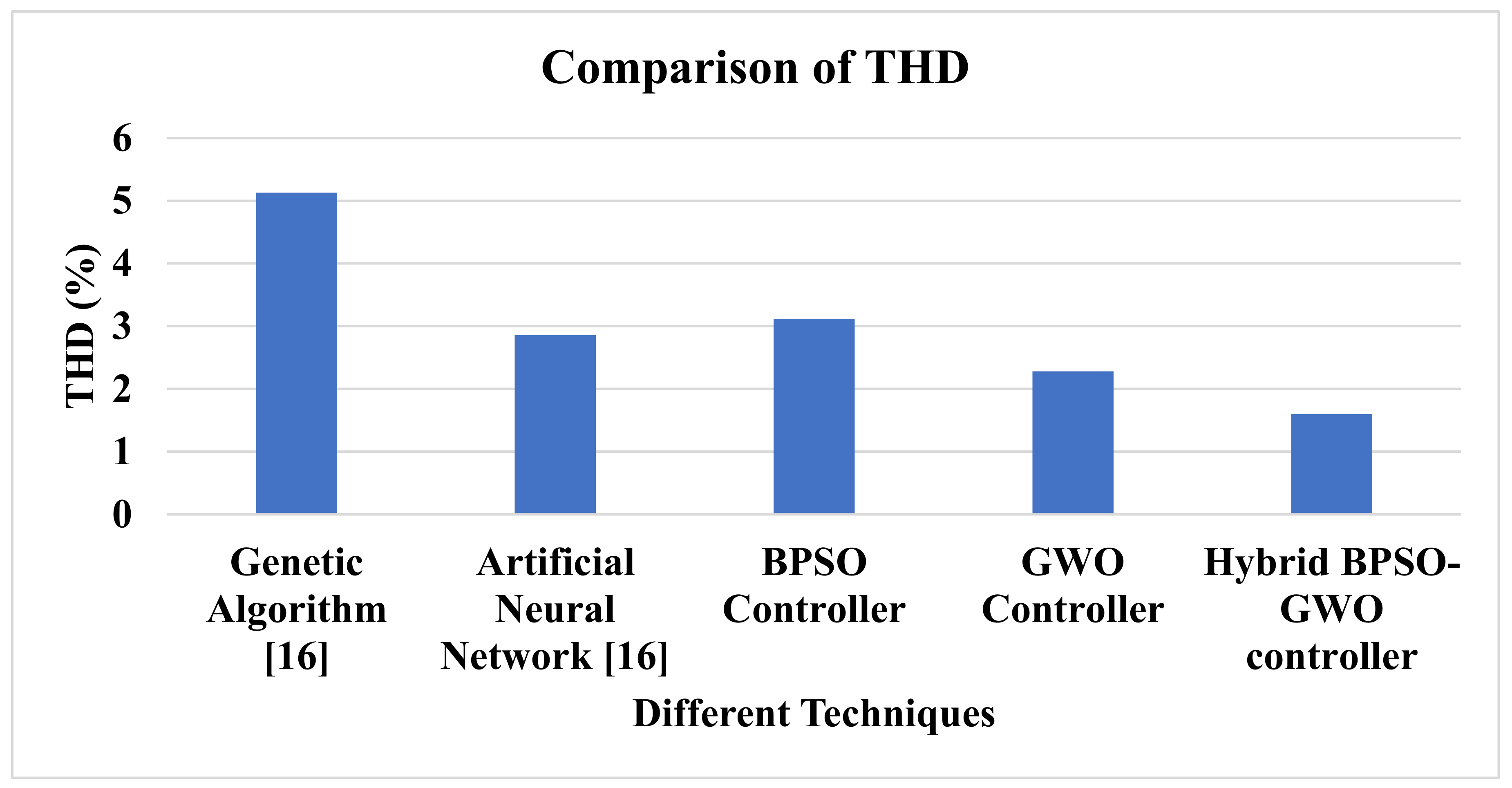
THD Analysis under Linear and Nonlinear Loads
8. Conclusions
Author Contributions
Funding
Institutional Review Board Statement
Informed Consent Statement
Data Availability Statement
Acknowledgments
Conflicts of Interest
Nomenclature
| Open circuit voltage | |
| Short circuit current | |
| MPPT current | |
| MPPT voltage | |
| Maximum voltage | |
| and | Capacitances |
| Maximum power | |
| Change in temperature | |
| Maximum current | |
| Cell temperature | |
| Particle position | |
| Velocity | |
| and | Random values |
| Personal best | |
| Global best | |
| Ω | Inertia weight |
| Sigmoid limiting transformation | |
| Grey wolf’s position vector | |
| ; | Prey’s location vector |
| Alpha wolf | |
| Beta wolf | |
| Delta wolf | |
| Omega wolf | |
| and ; | Coefficient vectors |
| . | Exploration rate |
| and | Position of the alpha, beta, and delta wolves |
| Maximum number of iterations | |
| Average position | |
| Best fitness value |
References
- Zhou, Y.; Li, H. Analysis and suppression of leakage current in cascaded-multilevel-inverter-based PV systems. IEEE Trans. Power Electron. 2013, 29, 5265–5277. [Google Scholar] [CrossRef]
- Jain, S.; Venu, S. A highly efficient and reliable inverter configuration based cascaded multilevel inverter for PV systems. IEEE Trans. Ind. Electron. 2016, 64, 2865–2875. [Google Scholar] [CrossRef]
- Das, M.K.; Jana, K.C.; Akanksha, S. Performance evaluation of an asymmetrical reduced switched multi-level inverter for a grid-connected PV system. IET Renew. Power Gener. 2013, 12, 252–263. [Google Scholar] [CrossRef]
- Sumit, K.C.; Chandan, C. A new asymmetric multilevel inverter topology suitable for solar PV applications with varying irradiance. IEEE Trans. Sustain. Energy 2017, 8, 1496–1506. [Google Scholar]
- Rajalakshmi, S.; Parthasarathy, R. Investigation of modified multilevel inverter topology for PV system. Microprocess. Microsyst. 2019, 71, 102870. [Google Scholar] [CrossRef]
- Jahan, H.K.; Abapour, M.; Zare, K.; Hosseini, S.H.; Blaabjerg, F.; Yang, Y. A Multilevel Inverter with Minimized Components Featuring Self-balancing and Boosting Capabilities for PV Applications. IEEE J. Emerg. Sel. Top. Power Electron. 2019, 1. [Google Scholar] [CrossRef]
- Bana, P.R.; Kaibalya, P.P.; Sanjeevikumar, P.; Mihet-Popa, L.; Panda, G.; Wu, J. Closed-loop control and performance evaluation of reduced part count multilevel inverter interfacing grid-connected PV system. IEEE Access 2020, 8, 75691–75701. [Google Scholar] [CrossRef]
- Ahmed, A.; Mohan, S.M.; Joung-Hu, P. An efficient single-sourced asymmetrical cascaded multilevel inverter with reduced leakage current suitable for single-stage PV systems. IEEE Trans. Energy Convers 2018, 34, 211–220. [Google Scholar] [CrossRef]
- Lingom, P.M.; Song-Manguelle, J.; Mon-Nzongo, D.L.; Costa Flesch, R.C.; Jin, T. Analysis and control of PV cascaded H-bridge multilevel inverter with failed cells and changing meteorological conditions. IEEE Trans. Power Electron. 2020, 36, 1777–1789. [Google Scholar] [CrossRef]
- Manoharan, M.S.; Ashraf, A.; Joung-Hu, P. A PV power conditioning system using nonregenerative single-sourced trinary asymmetric multilevel inverter with hybrid control scheme and reduced leakage current. IEEE Trans. Power Electron. 2016, 32, 7602–7614. [Google Scholar] [CrossRef]
- Kollimalla, S.K.; Mishra, M.K. Variable perturbation size adaptive P&O MPPT algorithm for sudden changes in irradiance. IEEE Trans. Sustain. Energy 2014, 5, 718–728. [Google Scholar]
- Elmetennani, S.; Laleg-Kirati, T.M.; Djemai, M.; Tadjine, M. New MPPT algorithm for PV applications based on hybrid dynamical approach. J. Process. Control 2016, 48, 14–24. [Google Scholar] [CrossRef]
- Keyrouz, F. Enhanced Bayesian Based MPPT Controller for PV Systems. IEEE Power Energy Technol. Syst. J. 2018, 5, 11–17. [Google Scholar] [CrossRef]
- Robles, A.; Carlos, J.T.G.; Omar, R.A. Fuzzy logic based MPPT controller for a PV system. Energies 2017, 10, 2036. [Google Scholar]
- Koad, R.B.A.; Ahmed, F.Z.; El-Shahat, A. A novel MPPT algorithm based on particle swarm optimization for photovoltaic systems. IEEE Trans. Sustain. Energy 2017, 8, 468–476. [Google Scholar] [CrossRef] [Green Version]
- Atiq, J.; Soori, P.K. Modelling of a grid connected solar PV system using MATLAB/Simulink. Int. J. Simul. Syst. Sci. Technol. 2017, 17, 45.1–45.7. [Google Scholar]
- Hariri, M.H.M.; Desa, M.K.M.; Masri, S.; Zainuri, M.A.A.M. Grid-Connected PV Generation System—Components and Challenges: A Review. Energies 2020, 13, 4279. [Google Scholar] [CrossRef]
- Shankar, J.G.; Belwin Edward, J.; Sathish Kumar, K.; Jaocb Raglend, I. A 31-level asymmetrical cascaded multilevel inverter with DC-DC flyback converter for photovoltaic system. In Proceedings of the 2017 International Conference on High Voltage Engineering and Power Systems (ICHVEPS), Denpasar, Indonesia, 2–5 October 2017; pp. 277–282. [Google Scholar]
- Abdulkadir, M.; Yatim, A.H.; Yusuf, S.T. An Improved PSO-Based MPPT Control Strategy for Photovoltaic Systems. Int. J. Photoenergy 2014, 2014, 1–11. [Google Scholar] [CrossRef] [Green Version]
- Almutairi, A.; Abo-Khalil, A.; Sayed, K.; Albagami, N. MPPT for a PV Grid-Connected System to Improve Efficiency under Partial Shading Conditions. Sustainability 2020, 12, 10310. [Google Scholar] [CrossRef]


| Parameters | Value |
|---|---|
| The voltage at maximum power point, Vmp | 54.7 V |
| Temperature coefficient of Voc | −0.27269 (%/°C) |
| Temperature coefficient of Isc | 0.061745 (%/°C) |
| Shunt resistance | 269.5934 ohms |
| Short-circuit current, Isc | 5.96 A |
| Series resistance | 0.37152 ohms |
| Open circuit voltage, Voc | 64.2 V |
| Maximum power | 305.226 W |
| Light generated current, IL | 6.0092 A |
| Diode saturation current | 0.000063 × 10⁻⁵A |
| Diode ideality factor | 0.94504 |
| Current at maximum power point of Isc | 5.58 A |
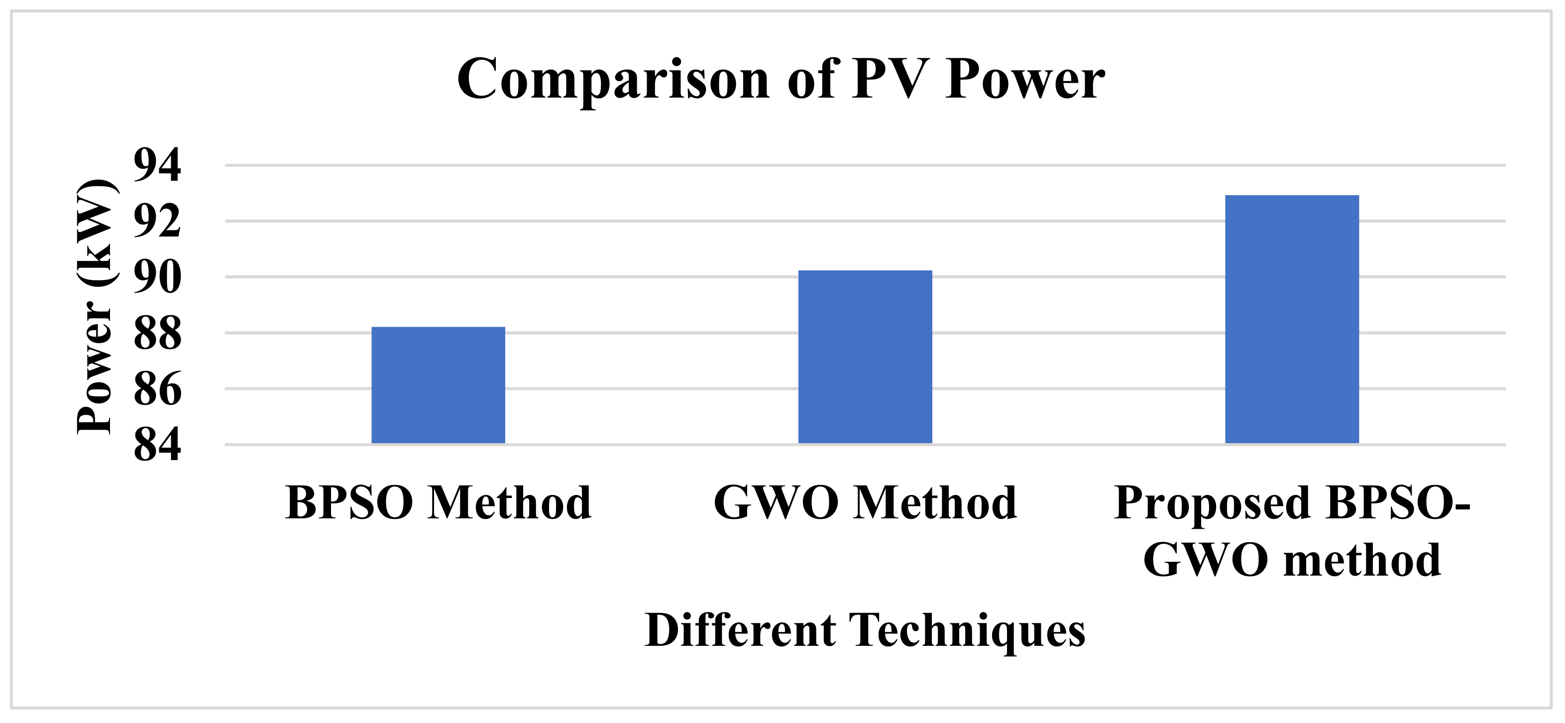
| Techniques | PV Power (kW) |
|---|---|
| BPSO method | 88.209 |
| GWO method | 90.238 |
| Proposed BPSO–GWO method | 92.930 |
| Techniques | THD (%) |
|---|---|
| 31-level MLI without a controller | 3.70 |
| 31-level MLI with the hybrid BPSO–GWO controller | 1.60 |
Publisher’s Note: MDPI stays neutral with regard to jurisdictional claims in published maps and institutional affiliations. |
© 2021 by the authors. Licensee MDPI, Basel, Switzerland. This article is an open access article distributed under the terms and conditions of the Creative Commons Attribution (CC BY) license (https://creativecommons.org/licenses/by/4.0/).
Share and Cite
Bandahalli Mallappa, P.K.; Garcia, H.M.; Quesada, G.V. Power Quality Enhancement in a Grid-Integrated Photovoltaic System Using Hybrid Techniques. Appl. Sci. 2021, 11, 10120. https://doi.org/10.3390/app112110120
Bandahalli Mallappa PK, Garcia HM, Quesada GV. Power Quality Enhancement in a Grid-Integrated Photovoltaic System Using Hybrid Techniques. Applied Sciences. 2021; 11(21):10120. https://doi.org/10.3390/app112110120
Chicago/Turabian StyleBandahalli Mallappa, Prasad Kumar, Herminio Martinez Garcia, and Guillermo Velasco Quesada. 2021. "Power Quality Enhancement in a Grid-Integrated Photovoltaic System Using Hybrid Techniques" Applied Sciences 11, no. 21: 10120. https://doi.org/10.3390/app112110120
APA StyleBandahalli Mallappa, P. K., Garcia, H. M., & Quesada, G. V. (2021). Power Quality Enhancement in a Grid-Integrated Photovoltaic System Using Hybrid Techniques. Applied Sciences, 11(21), 10120. https://doi.org/10.3390/app112110120