
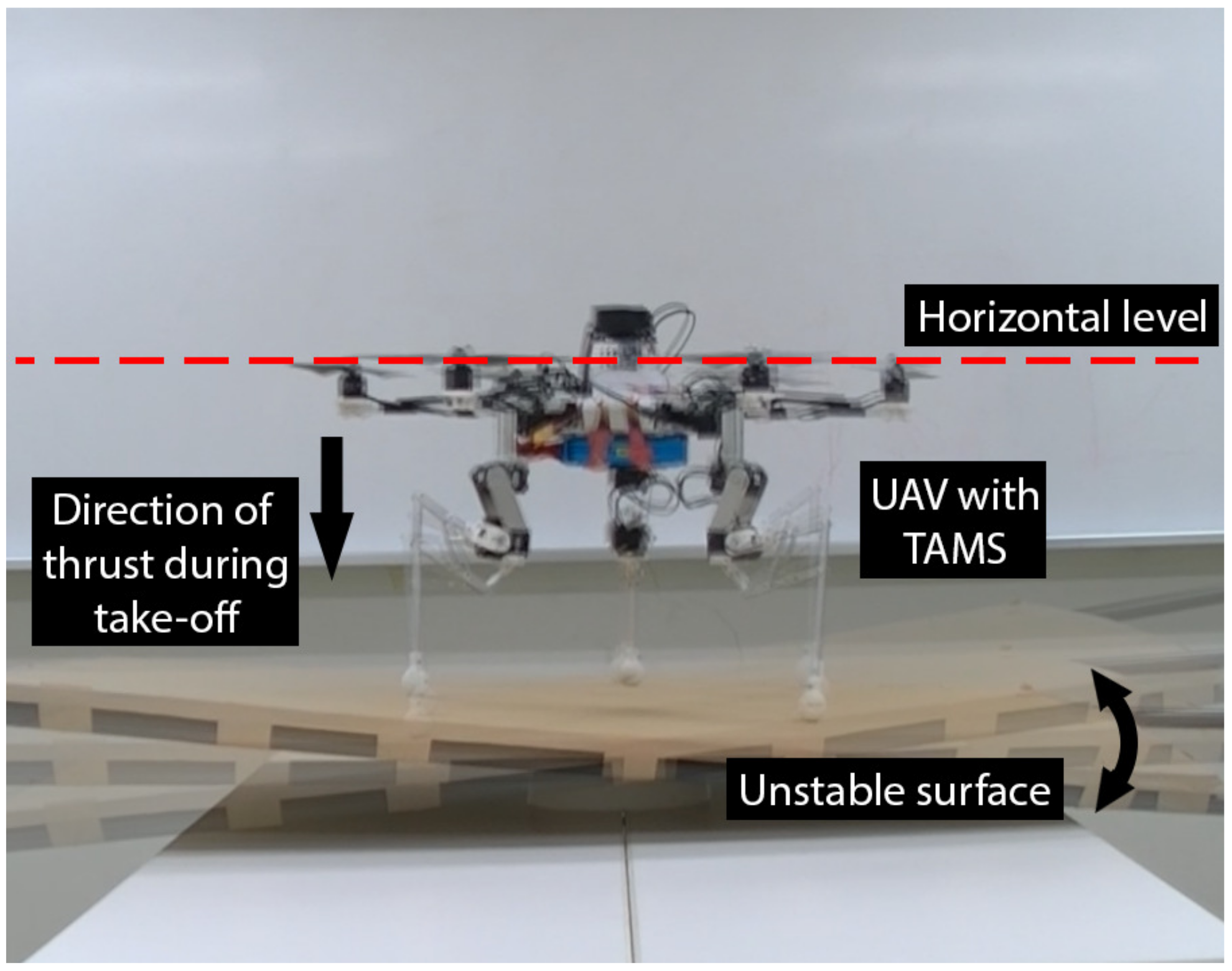
A Versatile Aerial Manipulator Design and Realization of UAV Take-Off from a Rocking Unstable Surface


Abstract
:1. Introduction
2. Versatile Task Manipulator System Design
- 1
- When designing the hardware for an adaptive landing system, the last link’s tip must remain perpendicular to the ground to orient the link parallel to the gravity vector, reducing the stress on its joint significantly. Therefore, only its height need be changed according to the terrain and requires a minimum of 2 DOF to maintain a perpendicular posture.
- 2
- When three manipulators are used to grab objects, the manipulators are regarded as a massive gripper. As a result, the angle of the link near the tip may be set, and only the link near the UAV’s base is operated to open and shut the massive gripper-like structure. To open and close this massive gripper structure, at least 1 DOF is required.
- 3
- When executing obstacle avoidance sideways of a UAV, the manipulators are extended or retracted while moving around the airframe, similar to the description in the adaptive landing condition (first case). Therefore, including yaw motion, to achieve this task, a minimum of 3 DOF is necessary.
3. Hardware System Design
4. Control
4.1. Angle Change
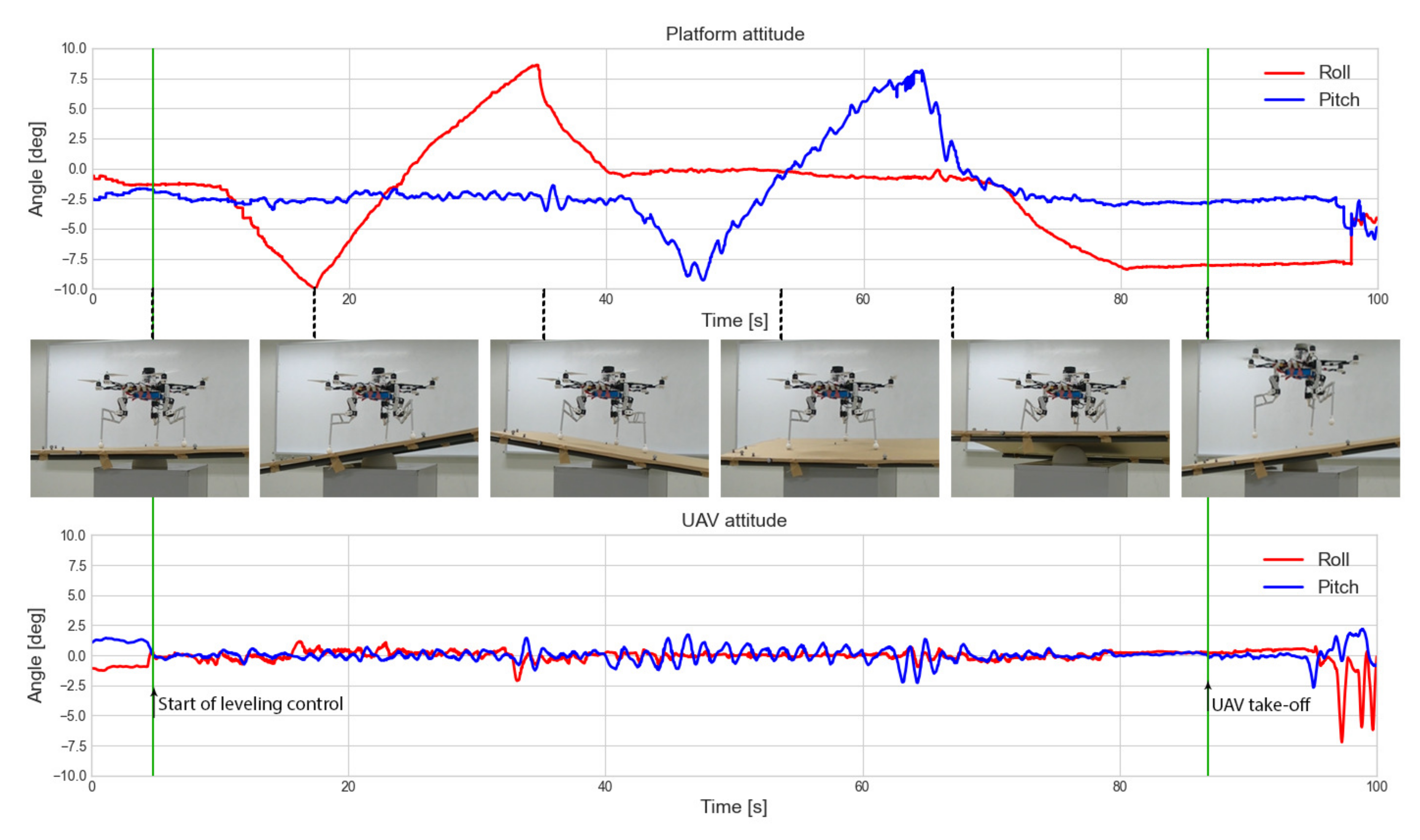
4.2. Adapting to a Surface after Landing
5. Experiments
6. Discussion
7. Conclusions
Supplementary Materials
Author Contributions
Funding
Conflicts of Interest
Abbreviations
| UAV | Unmanned aerial vehicle |
| VTOL | Vertical take-off and landing |
| DOF | Degree of freedom |
| IMU | Inertial measurement unit |
| PLA | Polylactic acid |
| COG | Center of gravity |
References
- Recchiuto, C.T.; Sgorbissa, A. Post-disaster assessment with unmanned aerial vehicles: A survey on practical implementations and research approaches. J. Field Robot. 2018, 35, 459–490. [Google Scholar] [CrossRef]
- Ezequiel, C.A.F.; Cua, M.; Libatique, N.C.; Tangonan, G.L.; Alampay, R.; Labuguen, R.T.; Favila, C.M.; Honrado, J.L.E.; Canos, V.; Devaney, C.; et al. UAV aerial imaging applications for post-disaster assessment, environmental management and infrastructure development. In Proceedings of the 2014 International Conference on Unmanned Aircraft Systems (ICUAS), Orlando, FL, USA, 27–30 May 2014; pp. 274–283. [Google Scholar]
- Korpela, C.; Orsag, M.; Oh, P. Towards valve turning using a dual-arm aerial manipulator. In Proceedings of the 2014 IEEE/RSJ International Conference on Intelligent Robots and Systems, Chicago, IL, USA, 14–18 September 2014; pp. 3411–3416. [Google Scholar]
- Papachristos, C.; Alexis, K.; Tzes, A. Efficient force exertion for aerial robotic manipulation: Exploiting the thrust-vectoring authority of a tri-tiltrotor uav. In Proceedings of the 2014 IEEE international conference on robotics and automation (ICRA), Hong Kong, China, 31 May–7 June 2014; pp. 4500–4505. [Google Scholar]
- Lin, T.J.; Long, S.; Stol, K.A. Automated perching of a multirotor UAV atop round timber posts. In Proceedings of the 2018 IEEE/ASME International Conference on Advanced Intelligent Mechatronics (AIM), Auckland, New Zealand, 9–12 July 2018; pp. 486–491. [Google Scholar]
- Pope, M.T.; Cutkosky, M.R. Thrust-assisted perching and climbing for a bioinspired UAV. In Conference on Biomimetic and Biohybrid Systems; Springer: Berlin/Heidelberg, Germany, 2016; pp. 288–296. [Google Scholar]
- Paul, H.; Ono, K.; Ladig, R.; Shimonomura, K. A multirotor platform employing a three-axis vertical articulated robotic arm for aerial manipulation tasks. In Proceedings of the 2018 IEEE/ASME International Conference on Advanced Intelligent Mechatronics (AIM), Auckland, New Zealand, 9–12 July 2018; pp. 478–485. [Google Scholar]
- Koparan, C.; Koc, A.B.; Privette, C.V.; Sawyer, C.B.; Sharp, J.L. Evaluation of a UAV-assisted autonomous water sampling. Water 2018, 10, 655. [Google Scholar] [CrossRef] [Green Version]
- Araar, O.; Aouf, N.; Vitanov, I. Vision based autonomous landing of multirotor UAV on moving platform. J. Intell. Robot. Syst. 2017, 85, 369–384. [Google Scholar] [CrossRef]
- Rodriguez-Ramos, A.; Sampedro, C.; Bavle, H.; De La Puente, P.; Campoy, P. A deep reinforcement learning strategy for UAV autonomous landing on a moving platform. J. Intell. Robot. Syst. 2019, 93, 351–366. [Google Scholar] [CrossRef]
- Manivannan, V.; Langley, J.P.; Costello, M.; Ruzzene, M. Rotorcraft slope landings with articulated landing gear. In Proceedings of the AIAA Atmospheric Flight Mechanics (AFM) Conference, Boston, MA, USA, 19–22 August 2013; p. 5160. [Google Scholar]
- Paul, H.; Miyazaki, R.; Ladig, R.; Shimonomura, K. TAMS: Development of a multipurpose three-arm aerial manipulator system. Adv. Robot. 2021, 35, 31–47. [Google Scholar] [CrossRef]
- Paul, H.; Miyazaki, R.; Ladig, R.; Shimonomura, K. Landing of a multirotor aerial vehicle on an uneven surface using multiple on-board manipulators. In Proceedings of the 2019 IEEE/RSJ International Conference on Intelligent Robots and Systems (IROS), Macau, China, 3–8 November 2019; pp. 1926–1933. [Google Scholar]
- Ikeda, T.; Yasui, S.; Minamiyama, S.; Ohara, K.; Ashizawa, S.; Ichikawa, A.; Okino, A.; Oomichi, T.; Fukuda, T. Stable impact and contact force control by UAV for inspection of floor slab of bridge. Adv. Robot. 2018, 32, 1061–1076. [Google Scholar] [CrossRef]
- Rönnau, A.; Heppner, G.; Nowicki, M.; Dillmann, R. LAURON V: A versatile six-legged walking robot with advanced maneuverability. In Proceedings of the 2014 IEEE/ASME International Conference on Advanced Intelligent Mechatronics, Besacon, France, 8–11 July 2014; pp. 82–87. [Google Scholar]
- Qin, L.; Liang, X.; Huang, H.; Chui, C.K.; Yeow, R.C.H.; Zhu, J. A versatile soft crawling robot with rapid locomotion. Soft Robot. 2019, 6, 455–467. [Google Scholar] [CrossRef] [PubMed]
- Bandyopadhyay, T.; Steindl, R.; Talbot, F.; Kottege, N.; Dungavell, R.; Wood, B.; Barker, J.; Hoehn, K.; Elfes, A. Magneto: A versatile multi-limbed inspection robot. In Proceedings of the 2018 IEEE/RSJ International Conference on Intelligent Robots and Systems (IROS), Madrid, Spain, 1–5 October 2018; pp. 2253–2260. [Google Scholar]
- Multi-Tasking Robots—Doing the Dangerous Work, so Humans Don’t Have to. Available online: https://stfc.ukri.org/news-events-and-publications/features/multi-tasking-robots/ (accessed on 11 June 2021).
- Motlagh, N.H.; Bagaa, M.; Taleb, T. UAV-based IoT platform: A crowd surveillance use case. IEEE Commun. Mag. 2017, 55, 128–134. [Google Scholar] [CrossRef] [Green Version]
- Mathew, N.; Smith, S.L.; Waslander, S.L. Planning paths for package delivery in heterogeneous multirobot teams. IEEE Trans. Autom. Sci. Eng. 2015, 12, 1298–1308. [Google Scholar] [CrossRef]
- Doherty, P.; Rudol, P. A UAV search and rescue scenario with human body detection and geolocalization. In Australasian Joint Conference on Artificial Intelligence; Springer: Berlin/Heidelberg, Germany, 2007; pp. 1–13. [Google Scholar]
- Olsson, P.M.; Kvarnström, J.; Doherty, P.; Burdakov, O.; Holmberg, K. Generating UAV communication networks for monitoring and surveillance. In Proceedings of the 2010 11th International Conference on Control Automation Robotics & Vision, Singapore, 7–10 December 2010; pp. 1070–1077. [Google Scholar]
- Malandrino, F.; Rottondi, C.; Chiasserini, C.F.; Bianco, A.; Stavrakakis, I. Multiservice UAVs for Emergency Tasks in Post-disaster Scenarios. In Proceedings of the ACM MobiHoc Workshop on Innovative Aerial Communication Solutions for FIrst REsponders Network in Emergency Scenarios, Catania, Italy, 2 July 2019; pp. 18–23. [Google Scholar]
- Puttock, A.; Cunliffe, A.; Anderson, K.; Brazier, R.E. Aerial photography collected with a multirotor drone reveals impact of Eurasian beaver reintroduction on ecosystem structure. J. Unmanned Veh. Syst. 2015, 3, 123–130. [Google Scholar] [CrossRef]
- Ruggiero, F.; Lippiello, V.; Ollero, A. Aerial manipulation: A literature review. IEEE Robot. Autom. Lett. 2018, 3, 1957–1964. [Google Scholar] [CrossRef] [Green Version]
- Alaimo, A.; Artale, V.; Milazzo, C.; Ricciardello, A.; Trefiletti, L. Mathematical modeling and control of a hexacopter. In Proceedings of the 2013 International Conference on Unmanned Aircraft Systems (ICUAS), Atlanta, GA, USA, 28–31 May 2013; pp. 1043–1050. [Google Scholar]
- Pose, C.D.; Giribet, J.I.; Ghersin, A.S. Hexacopter fault tolerant actuator allocation analysis for optimal thrust. In Proceedings of the 2017 International Conference on Unmanned Aircraft Systems (ICUAS), Miami, FL, USA, 13–16 June 2017; pp. 663–671. [Google Scholar]
- Baskaya, E.; Hamandi, M.; Bronz, M.; Franchi, A. A Novel Robust Hexarotor Capable of Static Hovering in Presence of Propeller Failure. IEEE Robot. Autom. Lett. 2021, 6, 4001–4008. [Google Scholar]
- Mazeh, H.; Saied, M.; Shraim, H.; Francis, C. Fault-tolerant control of an hexarotor unmanned aerial vehicle applying outdoor tests and experiments. IFAC-PapersOnLine 2018, 51, 312–317. [Google Scholar] [CrossRef]
- Suarez, A.; Jimenez-Cano, A.E.; Vega, V.M.; Heredia, G.; Rodriguez-Castaño, A.; Ollero, A. Design of a lightweight dual arm system for aerial manipulation. Mechatronics 2018, 50, 30–44. [Google Scholar] [CrossRef] [Green Version]
- Kim, S.; Seo, H.; Choi, S.; Kim, H.J. Vision-guided aerial manipulation using a multirotor with a robotic arm. IEEE/ASME Trans. Mechatronics 2016, 21, 1912–1923. [Google Scholar] [CrossRef]
- Molina, J.; Hirai, S. Pruning tree-branches close to electrical power lines using a skew-gripper and a multirotor helicopter. In Proceedings of the 2017 IEEE International Conference on Advanced Intelligent Mechatronics (AIM), Munich, Germany, 3–7 July 2017; pp. 1123–1128. [Google Scholar]
- Rashad, R.; Engelen, J.B.; Stramigioli, S. Energy tank-based wrench/impedance control of a fully-actuated hexarotor: A geometric port-hamiltonian approach. In Proceedings of the 2019 International Conference on Robotics and Automation (ICRA), Montreal, QC, Canada, 20–24 May 2019; pp. 6418–6424. [Google Scholar]
- Ladig, R.; Paul, H.; Miyazaki, R.; Shimonomura, K. Aerial Manipulation Using Multirotor UAV: A Review from the Aspect of Operating Space and Force. J. Robot. Mechatronics 2021, 33, 196–204. [Google Scholar] [CrossRef]
- Ollero, A.; Tognon, M.; Suarez, A.; Lee, D.; Franchi, A. Past, Present, and Future of Aerial Robotic Manipulators. IEEE Trans. Robot. 2021, 1–20. [Google Scholar] [CrossRef]


| Parameter | Value | |
|---|---|---|
| Whole robot | Width | 640 [mm] |
| Maximum height | 540 [mm] | |
| Total weight | 3000 [g] | |
| Rotors | 6 | |
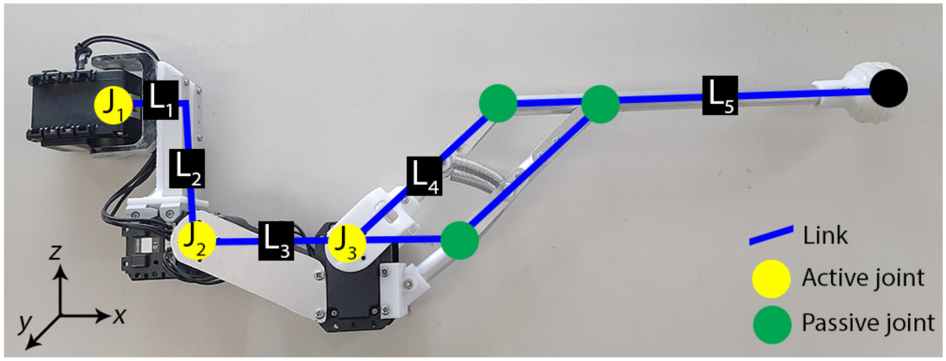
| Single manipulator | DOF | 3 |
| Link lengths (L1, L2, L3, L4, L5) | 50 [mm], 40 [mm], 100 [mm], 95 [mm], 205 [mm] | |
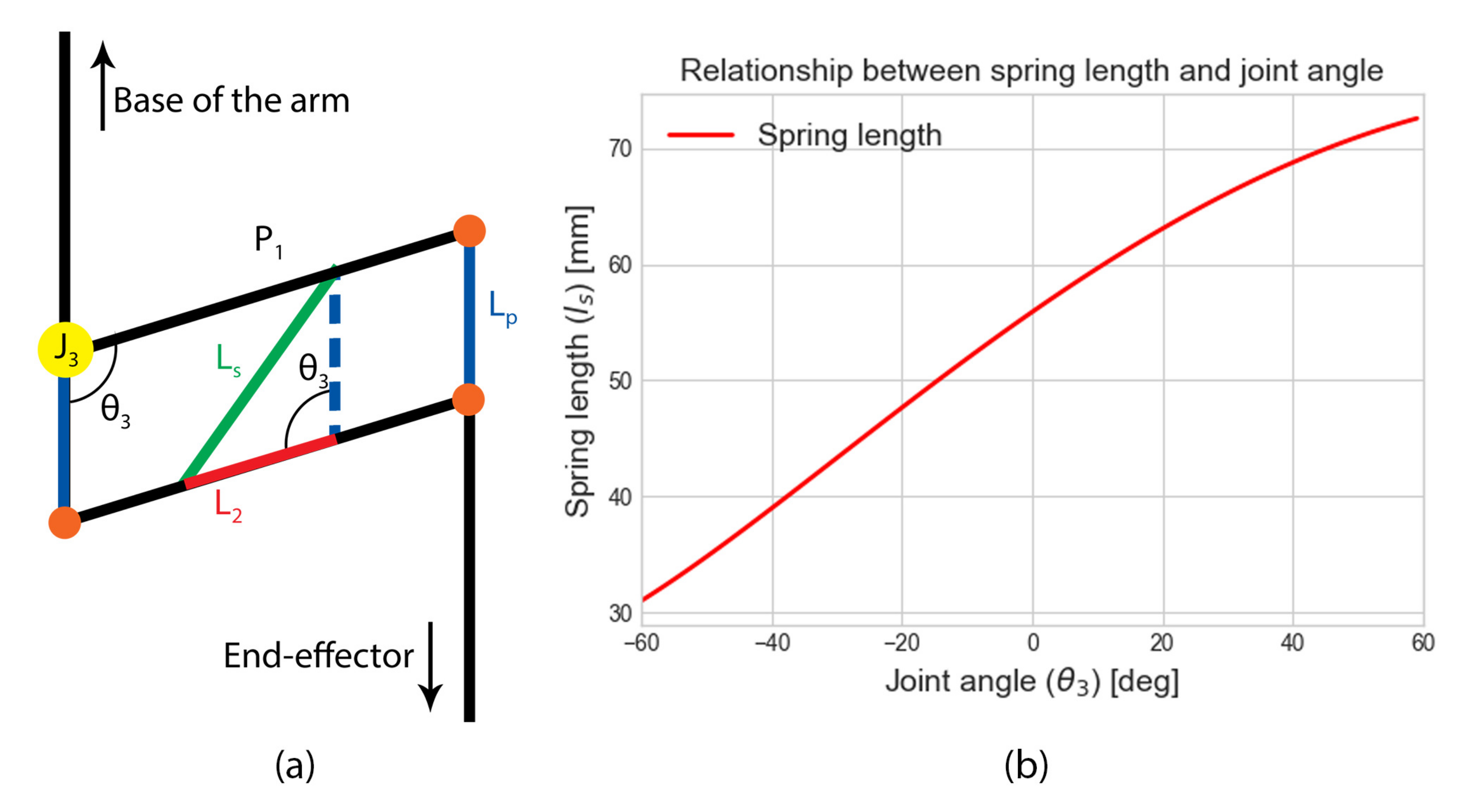
| Joint angle range (J1, J2, J3) | −100[] to 100[], −190[] to 90[], −60[] to 60[] | |
| Maximum width | 5 [mm] | |
| Weight | 330 [g] |
Publisher’s Note: MDPI stays neutral with regard to jurisdictional claims in published maps and institutional affiliations. |
© 2021 by the authors. Licensee MDPI, Basel, Switzerland. This article is an open access article distributed under the terms and conditions of the Creative Commons Attribution (CC BY) license (https://creativecommons.org/licenses/by/4.0/).
Share and Cite
Paul, H.; Miyazaki, R.; Kominami, T.; Ladig, R.; Shimonomura, K. A Versatile Aerial Manipulator Design and Realization of UAV Take-Off from a Rocking Unstable Surface. Appl. Sci. 2021, 11, 9157. https://doi.org/10.3390/app11199157
Paul H, Miyazaki R, Kominami T, Ladig R, Shimonomura K. A Versatile Aerial Manipulator Design and Realization of UAV Take-Off from a Rocking Unstable Surface. Applied Sciences. 2021; 11(19):9157. https://doi.org/10.3390/app11199157
Chicago/Turabian StylePaul, Hannibal, Ryo Miyazaki, Takamasa Kominami, Robert Ladig, and Kazuhiro Shimonomura. 2021. "A Versatile Aerial Manipulator Design and Realization of UAV Take-Off from a Rocking Unstable Surface" Applied Sciences 11, no. 19: 9157. https://doi.org/10.3390/app11199157
APA StylePaul, H., Miyazaki, R., Kominami, T., Ladig, R., & Shimonomura, K. (2021). A Versatile Aerial Manipulator Design and Realization of UAV Take-Off from a Rocking Unstable Surface. Applied Sciences, 11(19), 9157. https://doi.org/10.3390/app11199157