
Design and Implementation of a Tether-Powered Hexacopter for Long Endurance Missions


Abstract
:1. Introduction
2. Design and Analysis
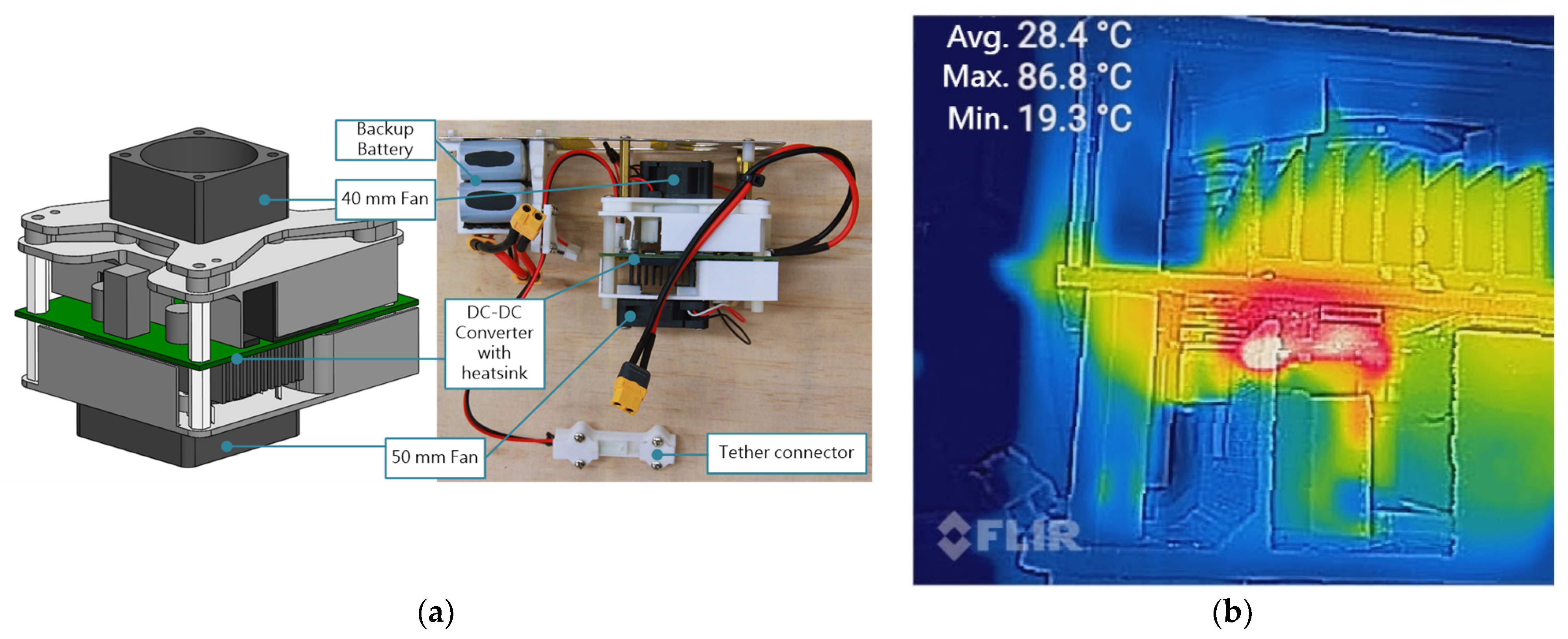
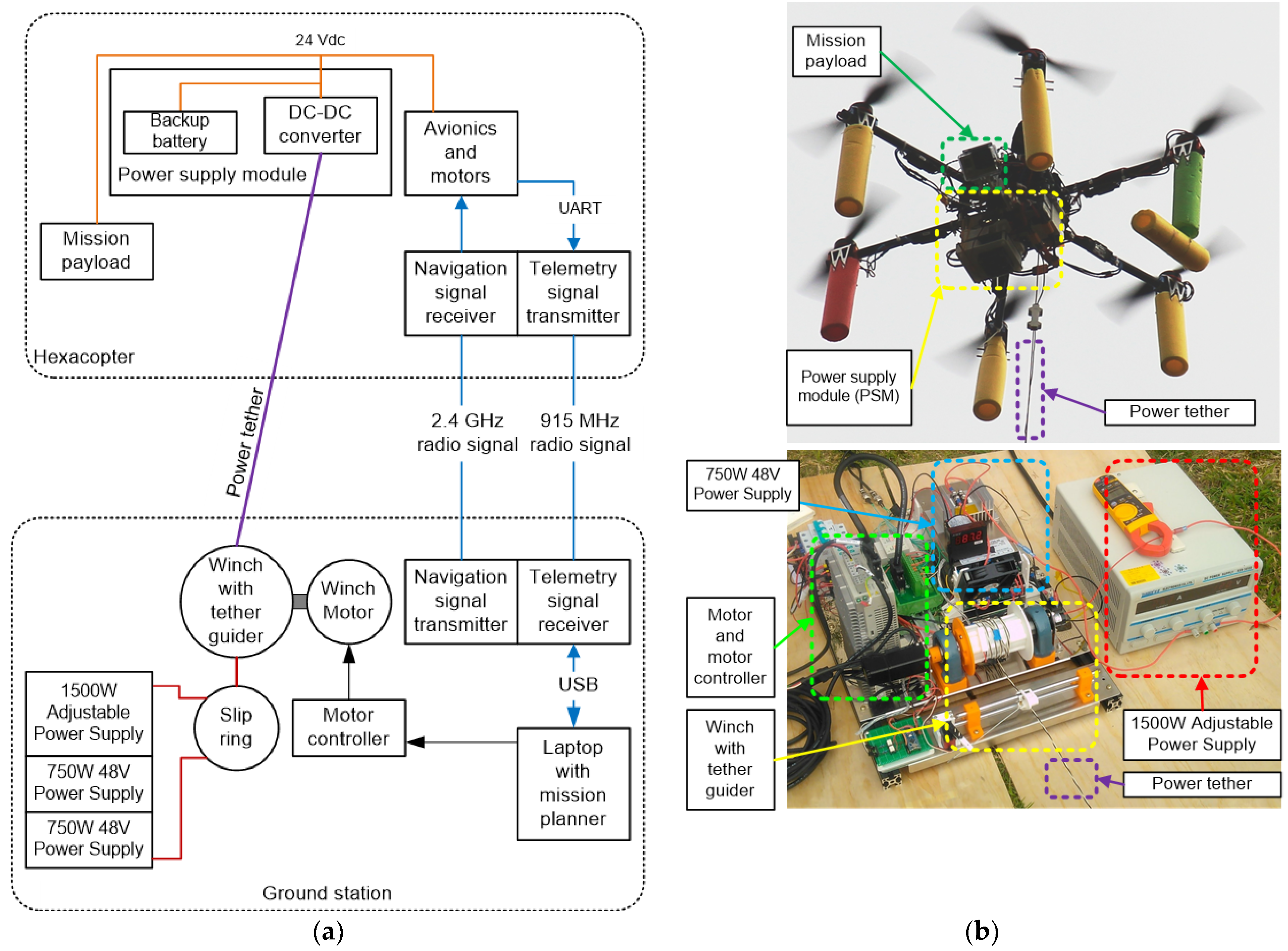
2.1. Ground Station
2.2. Hexacopter
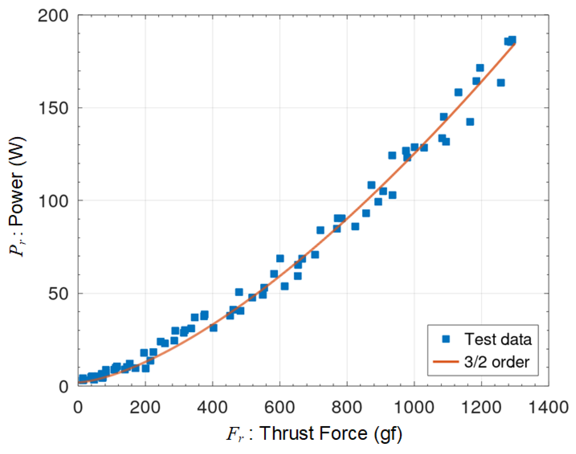
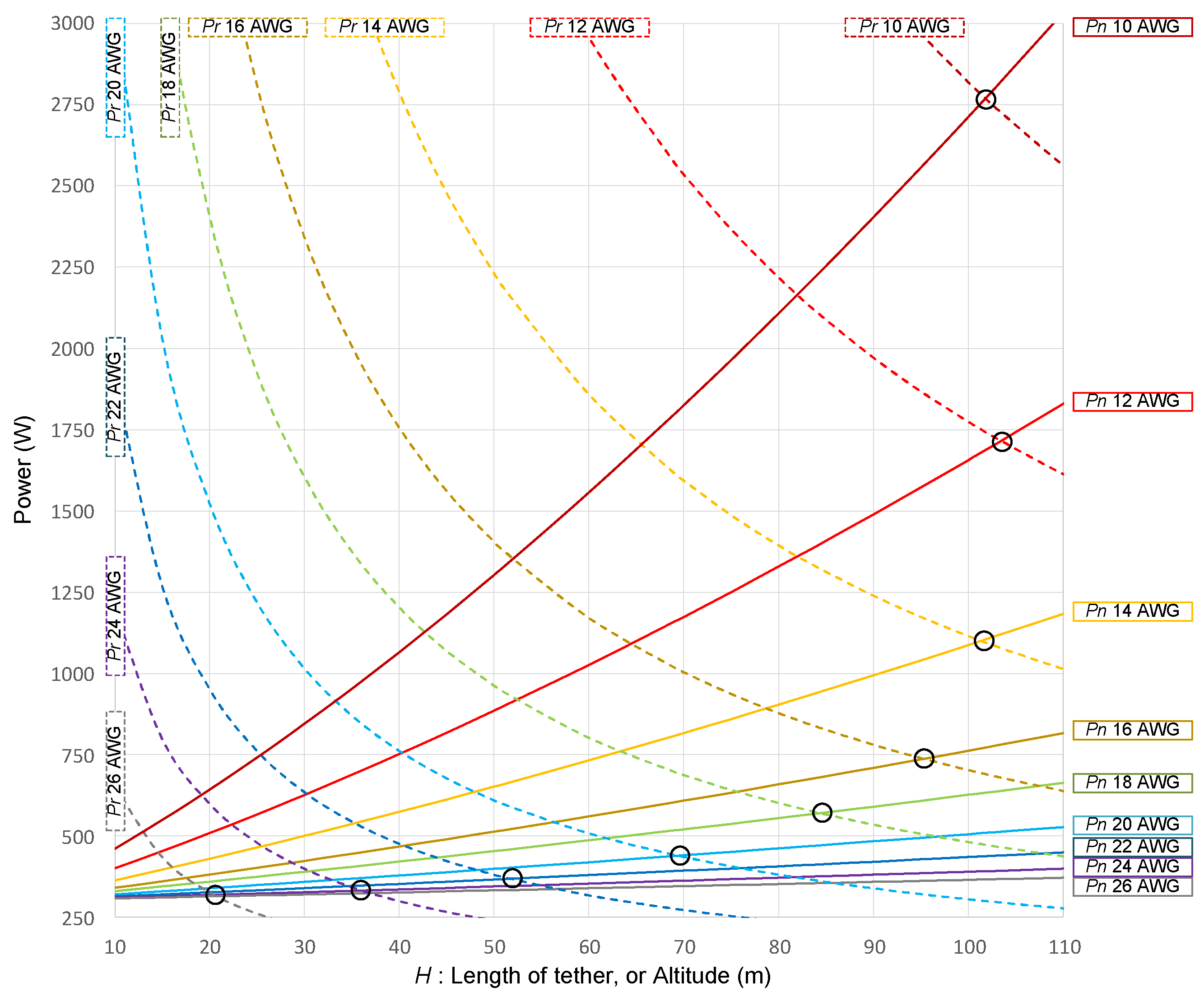
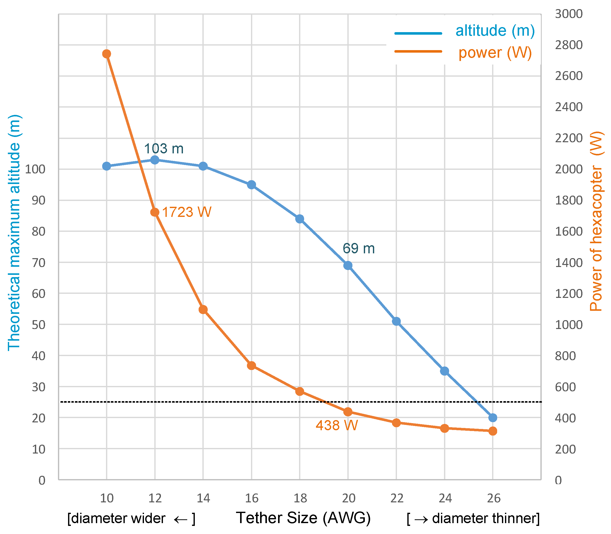
2.3. Tether Optimization
2.4. Margins for Safety
3. Experimental Results
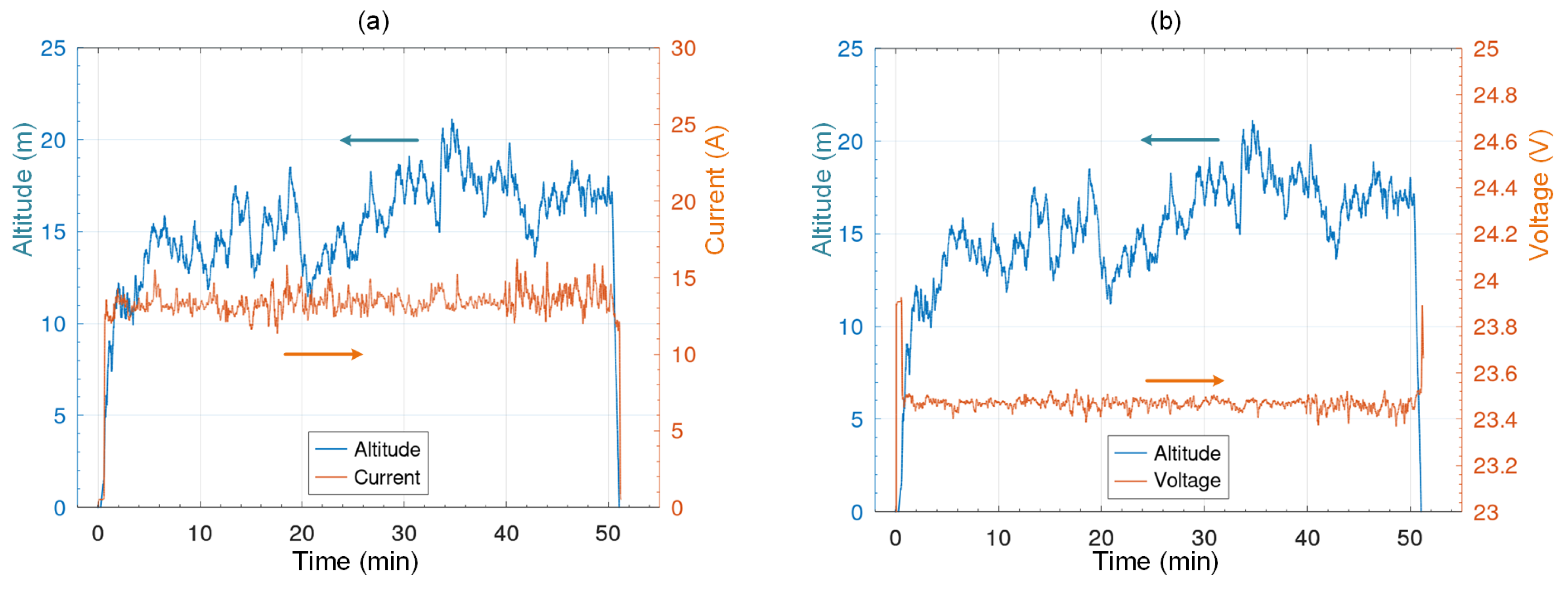
3.1. Functional Test
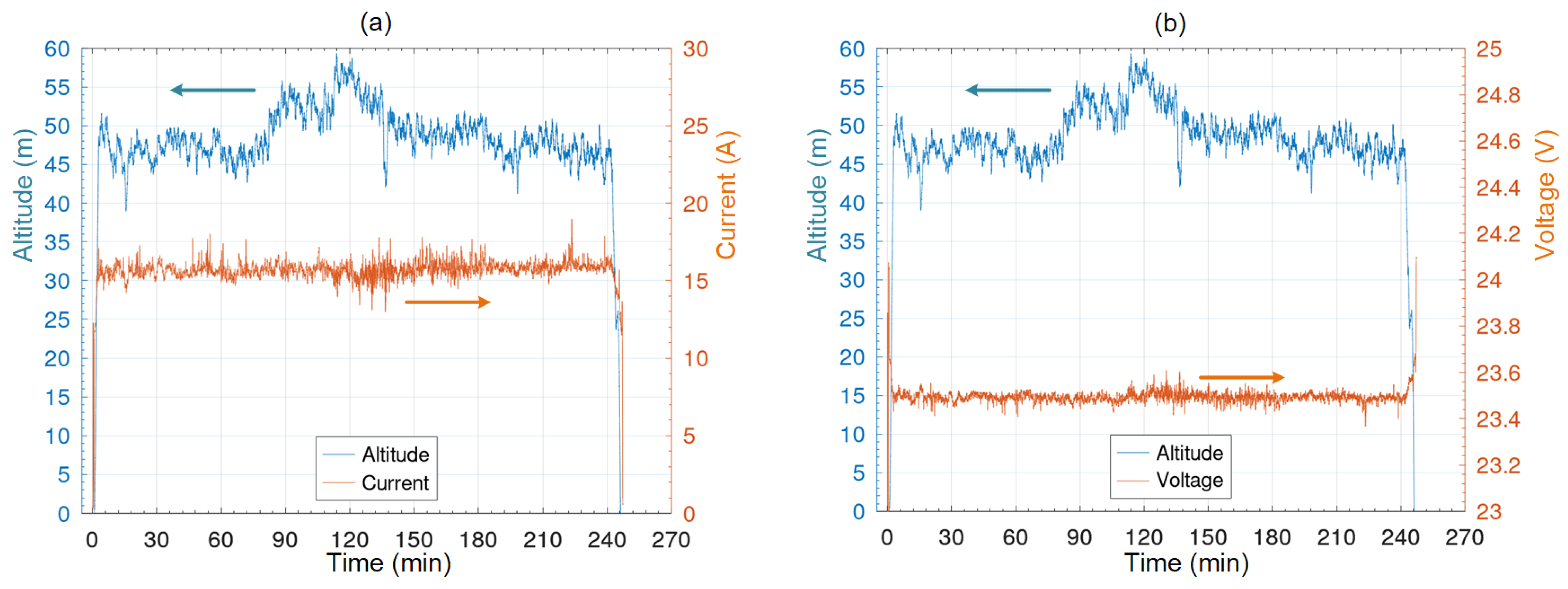
3.2. Endurance Test
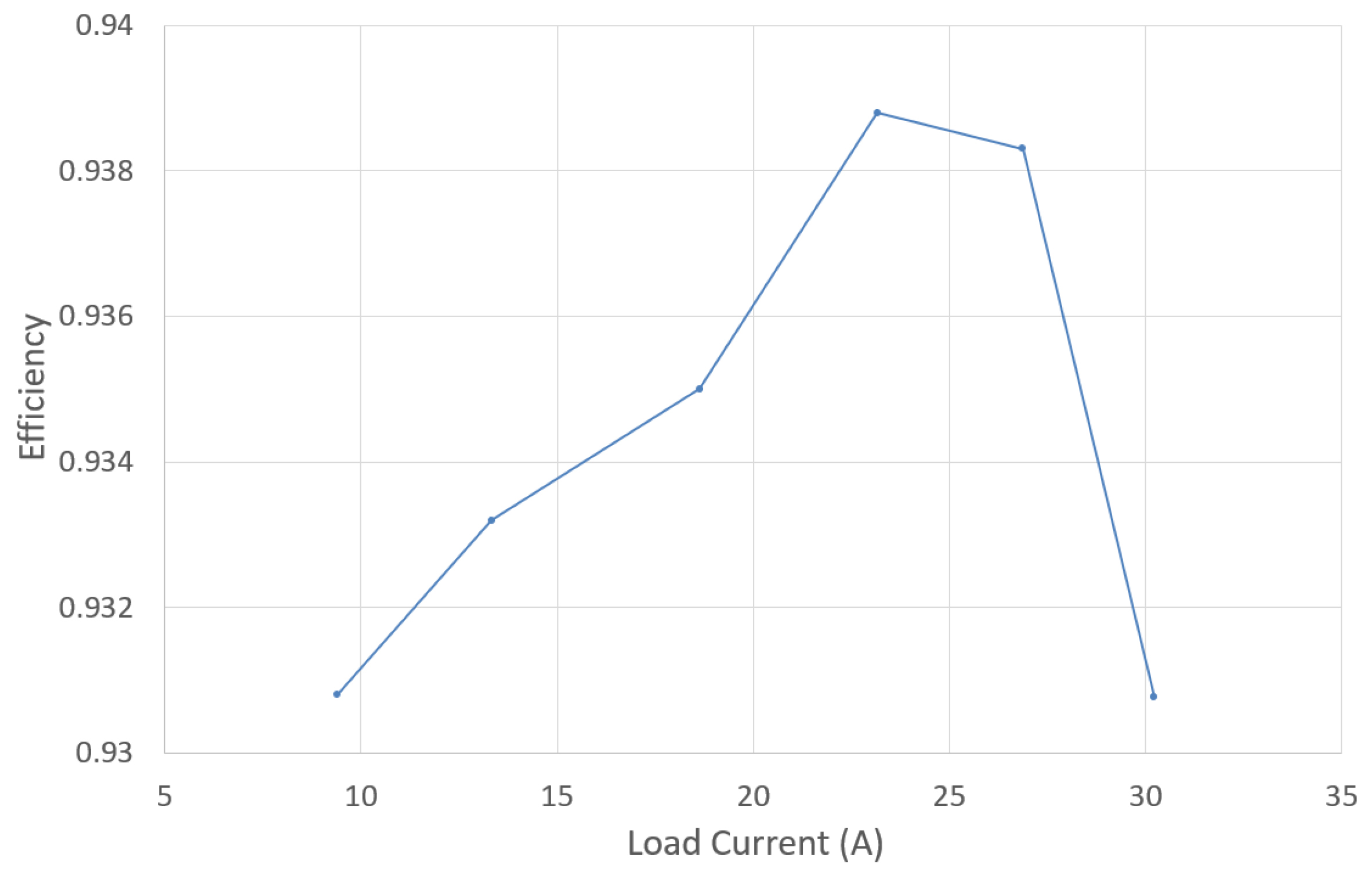
4. Discussions
- The extra forces caused by tether: The force caused by wind and tension on the tether may cause the hexacopter to produce extra thrust in order to balance itself;
- Imbalance of the hexacopter: Power supply and mission payload may cause an imbalance, thus requiring extra thrust for the hexacopter to maintain its altitude;
- Side wind: Since the hexacopter is set to hover at a fixed position throughout the test, side wind may cause it to produce more thrust than estimated in order to maintain its position.
5. Conclusions
Author Contributions
Funding
Institutional Review Board Statement
Informed Consent Statement
Acknowledgments
Conflicts of Interest
Appendix A. Details of Winch Control

| Flight Scenarios | Ascend | Hover & Slowly Descend | Fast Descend |
|---|---|---|---|
| Reference winch torque * (mNm) | −16 | 64 | 160 |
| Maximum winch speed (rpm) | 200 | 200 | 200 |
| Maximum tether tension * (gf) | −50 | 201 | 502 |
| Minimum tether tension * (gf) | −30 | 118 | 297 |
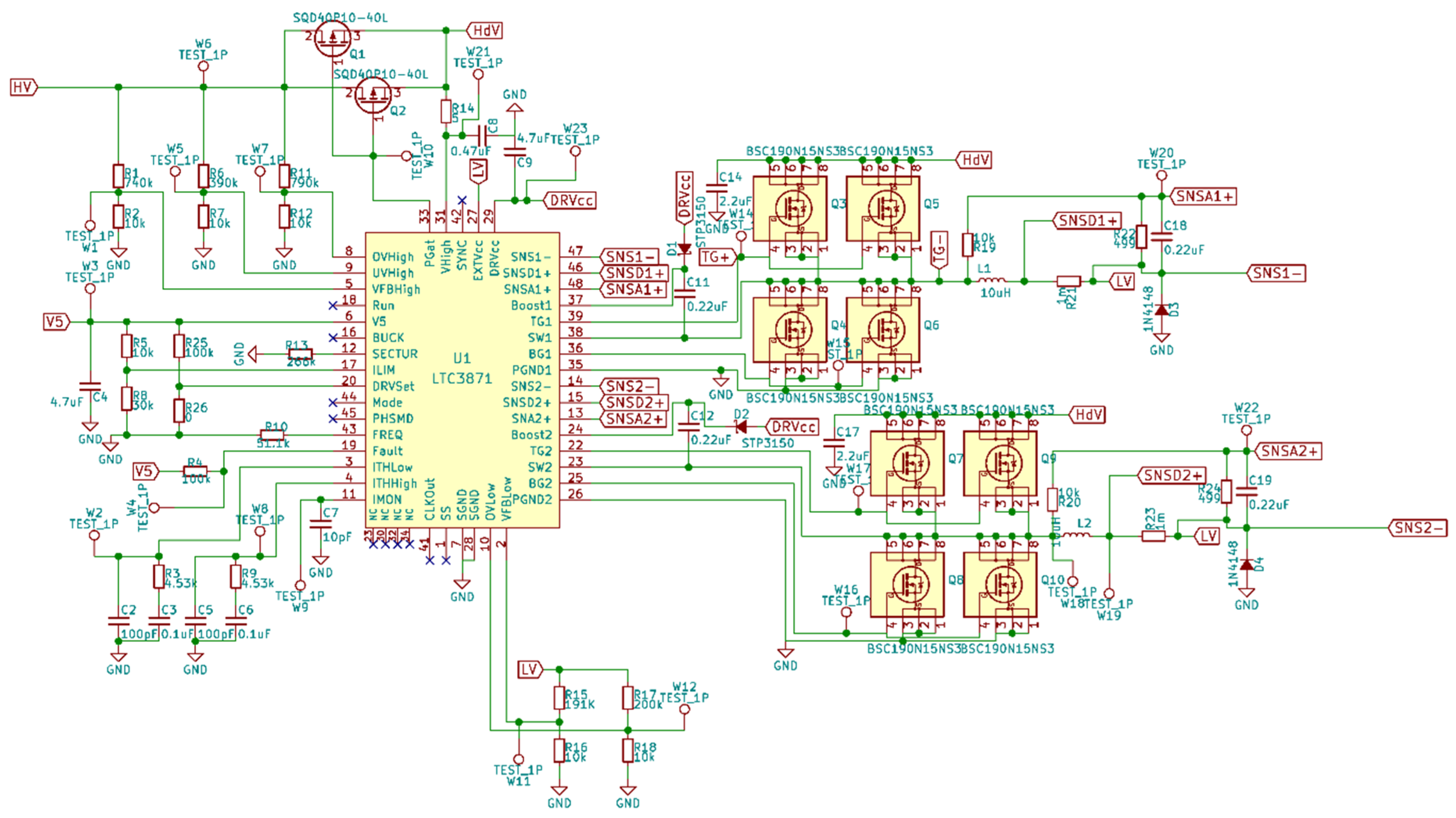
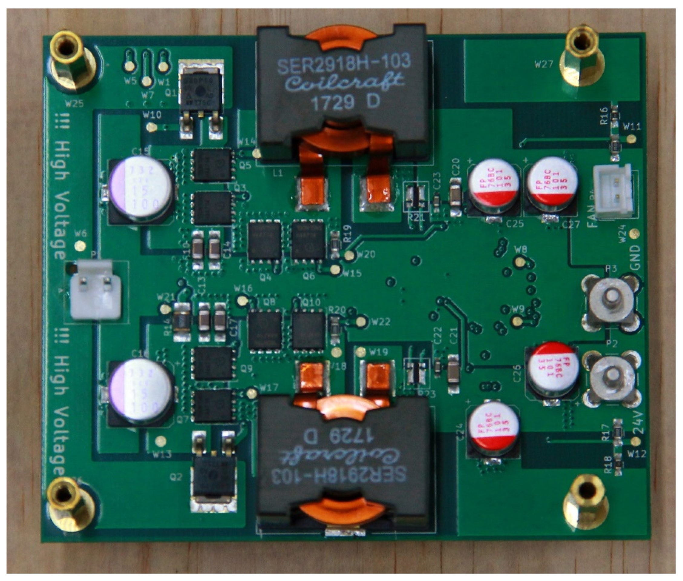
Appendix B. Details of DC-DC Convertor


References
- Beekman, D.W.; Islam, M.S.; Dutta, A.K. Micro air vehicle endurance versus battery size. In Proceedings of the Micro- and Nanotechnology Sensors, Systems, and Applications II, Orlando, FL, USA, 5–9 April 2010. [Google Scholar]
- Neitzke, K.-P. Rotary Wing Micro Air Vehicle Endurance. In Proceedings of the International Micro Air Vehicle Conference and Flight Competition IMAV, Toulouse, France, 17–20 September 2013; pp. 16–25. [Google Scholar]
- Abdilla, A.; Richards, A.; Burrow, S. Power and endurance modelling of battery-powered rotorcraft. In Proceedings of the 2015 IEEE/RSJ International Conference on Intelligent Robots and Systems (IROS), Hamburg, Germany, 28 September–3 October 2015; pp. 675–680. [Google Scholar]
- Gatti, M.; Giulietti, F.; Turci, M. Maximum endurance for battery-powered rotary-wing aircraft. Aerosp. Sci. Technol. 2015, 45, 174–179. [Google Scholar] [CrossRef]
- Avanzini, G.; de Angelis, E.L.; Giulietti, F. Optimal performance and sizing of a battery-powered aircraft. Aerosp. Sci. Technol. 2016, 59, 132–144. [Google Scholar] [CrossRef]
- Abdilla, A.; Richards, A.; Burrow, S. Endurance Optimisation of Battery-Powered Rotorcraft. In Towards Autonomous Robotic Systems; Lecture Notes in Computer Science; Springer: Cham, Switzerland, 2015; pp. 1–12. ISBN 978-3-319-22416-9. [Google Scholar]
- Chang, T.; Yu, H. Improving Electric Powered UAVs’ Endurance by Incorporating Battery Dumping Concept. Procedia Eng. 2015, 99, 168–179. [Google Scholar] [CrossRef] [Green Version]
- Roberts, J.F.; Zufferey, J.C.; Floreano, D. Energy management for indoor hovering robots. In Proceedings of the 2008 IEEE/RSJ International Conference on Intelligent Robots and Systems, Nice, France, 22–26 September 2008; pp. 1242–1247. [Google Scholar]
- Verbeke, J.; Hulens, D.; Ramon, H.; Goedeme, T.; De Schutter, J. The design and construction of a high endurance hexacopter suited for narrow corridors. In Proceedings of the 2014 International Conference on Unmanned Aircraft Systems (ICUAS), Orlando, FL, USA, 27–30 May 2014; pp. 543–551. [Google Scholar]
- Vu, N.A.; Dang, D.K.; Le Dinh, T. Electric propulsion system sizing methodology for an agriculture multicopter. Aerosp. Sci. Technol. 2019, 90, 314–326. [Google Scholar] [CrossRef]
- Winslow, J.; Benedict, M.; Hrishikeshavan, V.; Chopra, I. Design, development, and flight testing of a high endurance micro quadrotor helicopter. Int. J. Micro Air Veh. 2016, 8, 155–169. [Google Scholar] [CrossRef] [Green Version]
- Jung, S. Development of Path Planning Tool for Unmanned System Considering Energy Consumption. Appl. Sci. 2019, 9, 3341. [Google Scholar] [CrossRef] [Green Version]
- Kim, S.-B.; Lee, S.-H. Battery Balancing Algorithm for an Agricultural Drone Using a State-of-Charge-Based Fuzzy Controller. Appl. Sci. 2020, 10, 5277. [Google Scholar] [CrossRef]
- Lin, C.E.; Supsukbaworn, T. Development of Dual Power Multirotor System. Int. J. Aerosp. Eng. 2017, 2017, 1–19. [Google Scholar] [CrossRef]
- Mukhopadhyay, S.; Fernandes, S.; Shihab, M.; Waleed, D. Using Small Capacity Fuel Cells Onboard Drones for Battery Cooling: An Experimental Study. Appl. Sci. 2018, 8, 942. [Google Scholar] [CrossRef] [Green Version]
- Kiribayashi, S.; Ashizawa, J.; Nagatani, K. Modeling and design of tether powered multicopter. In Proceedings of the 2015 IEEE International Symposium on Safety, Security, and Rescue Robotics (SSRR), West Lafayette, IN, USA, 18–20 October 2015; pp. 1–7. [Google Scholar]
- Samarathunga, W.; Wang, G.; Wang, S. Heavy Payload Tethered Hexaroters for Agricultural Applications: Power Supply Design. International Research Journal of Engineering and Technology. 2015, 2, 641–645. [Google Scholar]
- Wang, K.-Y.; Lee, P.-H.; Hung, S.-K. Optimum electric cable selection for kite-like unmanned aerial vehicle. In Proceedings of the 2015 IEEE International Conference on Advanced Intelligent Mechatronics (AIM), Busan, Korea, 7–11 July 2015; pp. 1537–1540. [Google Scholar]
- Zikou, L.; Papachristos, C.; Tzes, A. The Power-over-Tether system for powering small UAVs: Tethering-line tension control synthesis. In Proceedings of the 2015 23rd Mediterranean Conference on Control and Automation (MED), Torremolinos, Spain, 16–19 June 2015; pp. 681–687. [Google Scholar]
- Samarathunga, W.; Wang, G.; Wang, S. Vehicle Design of Tethered Hexaroters for Heavy Payload Applications. In Proceedings of the 2015 IEEE International Conference on Computational Intelligence & Communication Technology, Ghaziabad, India, 13–14 February 2015; pp. 554–556. [Google Scholar]
- Vishnevsky, V.; Meshcheryakov, R. Experience of Developing a Multifunctional Tethered High-Altitude Unmanned Platform of Long-Term Operation. In Interactive Collaborative Robotics; Lecture Notes in Computer Science; Springer: Cham, Switzerland, 2019; pp. 236–244. ISBN 978-3-030-26118-4. [Google Scholar]
- Samarathunga, W.; Wang, G.; Wang, S. Auxiliary Power Unit Evaluation for Tethered UAV. Int. J. New Technol. Res. IJNTR 2016, 2, 72–75. [Google Scholar]
- Wang, G.; Samarathunga, W.; Wang, S. Uninterruptible Power Supply Design for Heavy Payload Tethered Hexaroters. Int. J. Emerg. Eng. Res. Technol. 2016, 4, 16–21. [Google Scholar]
- Vishnevsky, V.; Tereschenko, B.; Tumchenok, D.; Shirvanyan, A. Optimal Method for Uplink Transfer of Power and the Design of High-Voltage Cable for Tethered High-Altitude Unmanned Telecommunication Platforms. In Distributed Computer and Communication Networks; Communications in Computer and Information Science; Springer: Cham, Switzerland, 2017; pp. 240–247. ISBN 978-3-319-66836-9. [Google Scholar]
- Leishman, J.G. Principles of Helicopter Aerodynamics; Cambridge University Press: Cambridge, UK, 2003; ISBN 0521523966. [Google Scholar]
- [PMEL] Design and Implement of a Tether-Powered Hexacopter for Long Endurance Missions. Available online: https://youtu.be/WHNUWNx-FfY (accessed on 7 December 2021).
- CWB Observation Data Inquire System. Available online: https://e-service.cwb.gov.tw/HistoryDataQuery (accessed on 7 December 2021).


| Reference | Rotors | Power Source | Battery Capacity (mAh) | Weight w/o Battery (g) | Altitude (m) | Max Endurance (Min) | Remark |
|---|---|---|---|---|---|---|---|
| [2] Wanze | 4 | 7.4 V Battery | 8000 | 119 | NA | 34 | |
| [2] Ninja | 4 | 11.1 V Battery | 2000 | 352 | NA | 15 | |
| [3] | 4 | 11.1 V Battery | 2200 | ~359 | 1.5–2.5 | 17.8 | |
| [4] | 6 | 14.8 V Battery | 40,000 | 2000 | NA | 29.24 | |
| [6] | 4 | 11.1 V Battery | 2300 | ~360 | NA | 19 | Releasing empty battery |
| [8] | 4 | Battery (voltage NA) | 2100 | 416 | 1–2.5 | Battery only: 14 Battery + magnet: 102 | Using magnets to attach to the ceiling |
| [9] | 6 | 11.1 V Battery | 3471 | 3294 | NA | 36 | |
| [11] | 4 | 3.7 V Battery | 650 | 32 | NA | 31 | |
| [14] | 8 | 22.2 V Battery + Fuel | 5200 | 19,600 | NA | 60 |
| Specifications | Description |
|---|---|
| Weight of airframe | 2000 g |
| Hub-to-hub (diagonal) dimension | 680 mm |
| Flight controller (avionics) | 3DR Pixhawk with ArduPilot |
| Electrical speed controller (ESC) | Hobbywing Platinum 30A Pro 2-6S ESC |
| Brushless DC Motor | SunnySky V3508-29 KV380 |
| Propeller | 1255 carbon fiber propeller |
| Telemetry | 915 MHz transmitter |
| Power consumption by Avionics | 10 W approximately |
| Weight of power supply module (PSM) | 696 g |
| Nominal output voltage of PSM | 24 V |
| Nominal output power of PSM | 600 W |
| Energy capacity of backup battery | 36 Wh |
| Payload capacity | 1500 g |
| Weight of mission payload | 170 g |
| Power consumption by mission payload | Less than 5 W |
| Tether Size | Weight per Unit Length (d) | Resistivity per Unit Length (ρ) |
|---|---|---|
| 10 AWG | 103.3 g/m | 0.00088 Ω/m |
| 12 AWG | 65.9 g/m | 0.00568 Ω/m |
| 14 AWG | 42.3 g/m | 0.00904 Ω/m |
| 16 AWG | 26.9 g/m | 0.01435 Ω/m |
| 18 AWG | 19.8 g/m | 0.02095 Ω/m |
| 20 AWG | 13.0 g/m | 0.03310 Ω/m |
| 22 AWG | 8.8 g/m | 0.05296 Ω/m |
| 24 AWG | 5.9 g/m | 0.08422 Ω/m |
| 26 AWG | 4.3 g/m | 0.15484 Ω/m |
| Test Parameter | Functional Test | Endurance Test |
|---|---|---|
| Target endurance | 30 min | 240 min |
| Target altitude | 15 m | 50 m |
| Tether length | 26 m | 61 m |
| Ground supply voltage | fixed 90 V | 90 V or higher |
| Item | Value |
|---|---|
| Measured ground supply voltage | 98.1 V |
| Measured ground supply current | 6.6 A |
| Calculated ground supply power | 648 W |
| Measured tether resistance | 4.02 Ω |
| Calculated power consumption by tether | 175 W |
| Measured power consumption of hexacopter | 421 W |
| Theoretical power consumption of hexacopter | 438 W |
| Theoretical power consumption model inaccuracy | 3.88% |
Publisher’s Note: MDPI stays neutral with regard to jurisdictional claims in published maps and institutional affiliations. |
© 2021 by the authors. Licensee MDPI, Basel, Switzerland. This article is an open access article distributed under the terms and conditions of the Creative Commons Attribution (CC BY) license (https://creativecommons.org/licenses/by/4.0/).
Share and Cite
Chang, K.-H.; Hung, S.-K. Design and Implementation of a Tether-Powered Hexacopter for Long Endurance Missions. Appl. Sci. 2021, 11, 11887. https://doi.org/10.3390/app112411887
Chang K-H, Hung S-K. Design and Implementation of a Tether-Powered Hexacopter for Long Endurance Missions. Applied Sciences. 2021; 11(24):11887. https://doi.org/10.3390/app112411887
Chicago/Turabian StyleChang, Kai-Hung, and Shao-Kang Hung. 2021. "Design and Implementation of a Tether-Powered Hexacopter for Long Endurance Missions" Applied Sciences 11, no. 24: 11887. https://doi.org/10.3390/app112411887
APA StyleChang, K.-H., & Hung, S.-K. (2021). Design and Implementation of a Tether-Powered Hexacopter for Long Endurance Missions. Applied Sciences, 11(24), 11887. https://doi.org/10.3390/app112411887