1. Introduction
The reduction in the launch and space mission costs is one of the main objectives of the space industry. To this purpose, the development of small satellites (total mass less than 20 kg) has increased its relevance and, recently, the efforts of academic, scientific, and industrial communities have focused on the development of nano- and pico-satellites. These last ones, consisting of multiples of 10 × 10 × 10 cm
3 cubic units with a total mass from 0.1 kg to 10 kg, need to be equipped with secondary propulsion systems to satisfy the requirements for a multitude of maneuvers, such as orbit altitude modification, orbit inclination correction, drag compensation, constellation deployment from a shared launch and formation flight, and de-orbiting and the control of the re-entry process [
1]. Typically, the secondary propulsion system on-board small satellites should provide thrust forces between a few micro-newtons up to some milli-newtons, a high specific impulse (from some tens of seconds to some thousands of seconds), and an impulse bit ranging from the mNs range for relatively coarse attitude requirements down to nNs for very tight pointing requirements and very small spacecrafts. At the same time, it should satisfy stringent constraints of mass, volume, and power consumption, ranging from 0.25 W to 20 W, depending on the spacecraft’s total mass and, hence, the available nominal power [
2]. Furthermore, the higher the spacecraft weight is, the more the impulse bit is required, especially when attitude control and pointing must be performed in short firing intervals.
Furthermore, the need for microthruster miniaturization has met the continuous and rapid advancements in MEMS technologies experienced in the last twenty years, allowing for the development of different demonstrators of MEMS-based microthrusters [
3]. Among them, micro-resistojets represent an interesting choice thanks to the simplicity of their concept. When fueled by a liquid propellant, micro-resistojets are better known as VLMs. In this case, an electrical resistor provides the heat to vaporize and superheat the propellant into a properly designed micro-chamber. Therefore, the high enthalpy vapor is expanded through a micronozzle. Nowadays, they represent one of the most promising solutions for secondary propulsion able to provide nominal thrust levels in the range (0.5–2) mN [
4] and specific impulse above 100 s (see
Table 1), as required for the attitude control and the pointing systems of miniaturized spacecrafts [
5]. This combines with additional advantages, such as a high compactness and low mass, high integration capability, high reliability, and fast response, as underlined in [
4].
Compared to cold/hot gas microthrusters, they store the propellant in low-pressure and lightweight fuel tanks, eliminating the need for safe confinement and high-pressure storage. Consequently, weakly pressurized tanks storing propellant are coupled with a micro-valving system placed downstream to control the feeding pressure. Nowadays, the last one represents the easiest, cheapest, and most reliable propellant management system for application to micro-propulsion systems. An advantage of such a system is that the valve can be turned on and shut off for different run times. This allows matching requirements for attitude control of microsatellites in terms of a minimum impulse bit. Since the impulse bit is obtained by integrating the thrust over the maneuver run time, the minimum valve cycle time directly affects the minimum impulse bit achieved. Consequently, to ensure impulse bits ranging between nNs and mNs, valve-driven feeding systems must have open–close times less than 10 ms, in combination with thrust forces from μN to mN, as specified in [
6,
7]. In this regard, today, electrostatic, electromagnetic, and piezoelectric MEMS microvalves represent the most promising solutions [
8].
In the present paper, first, we propose a review focused on MEMS VLMs geometries and heating solutions proposed in the literature. Then, we focus on a critical aspect of these micro thrusters: the presence of boiling instabilities and reverse channel flow, which substantially impacts the MEMS VLMs performance and limits their applicability. Finally, we review the research focused on passive and active control of the boiling instabilities, based on VLM geometry optimization and active heating strategies, respectively.
2. VLM Design and Manufacturing: State of the Art
Figure 1 shows the working principle of a VLM where the propellant management system (storage and feeding), the heating chamber, and the micronozzle represent the main sub-systems [
1]. After propellant injection into an inlet manifold, the heating process undergoes into the heating chamber before the supersonic expansion of the vapor flow occurring through the micronozzle.
The first concept of a silicon-based MEMS VLM was developed at the end of the 1990s, thanks to Mueller’s studies [
9,
10,
11]. They manufactured the device shown in
Figure 2a and performed a characterization of the heat losses in relation to its packaging and the assessment of the influence of the feeding pressure on the vaporization process. Later, different configurations, materials, and manufacturing technologies were investigated, as summarized in Gao et al. [
5].
In the field of silicon technology, Mukerjee et al. [
12] developed a MEMS-based VLM using water as a propellant, which was equipped with an external heater (see
Figure 2b). Their experiments showed thrust force magnitudes ranging between 0.15 mN and 0.46 mN. Similarly, Maurya et al. [
13] first designed and fabricated a water-fed silicon-based VLM with an integrated micro-heater (see
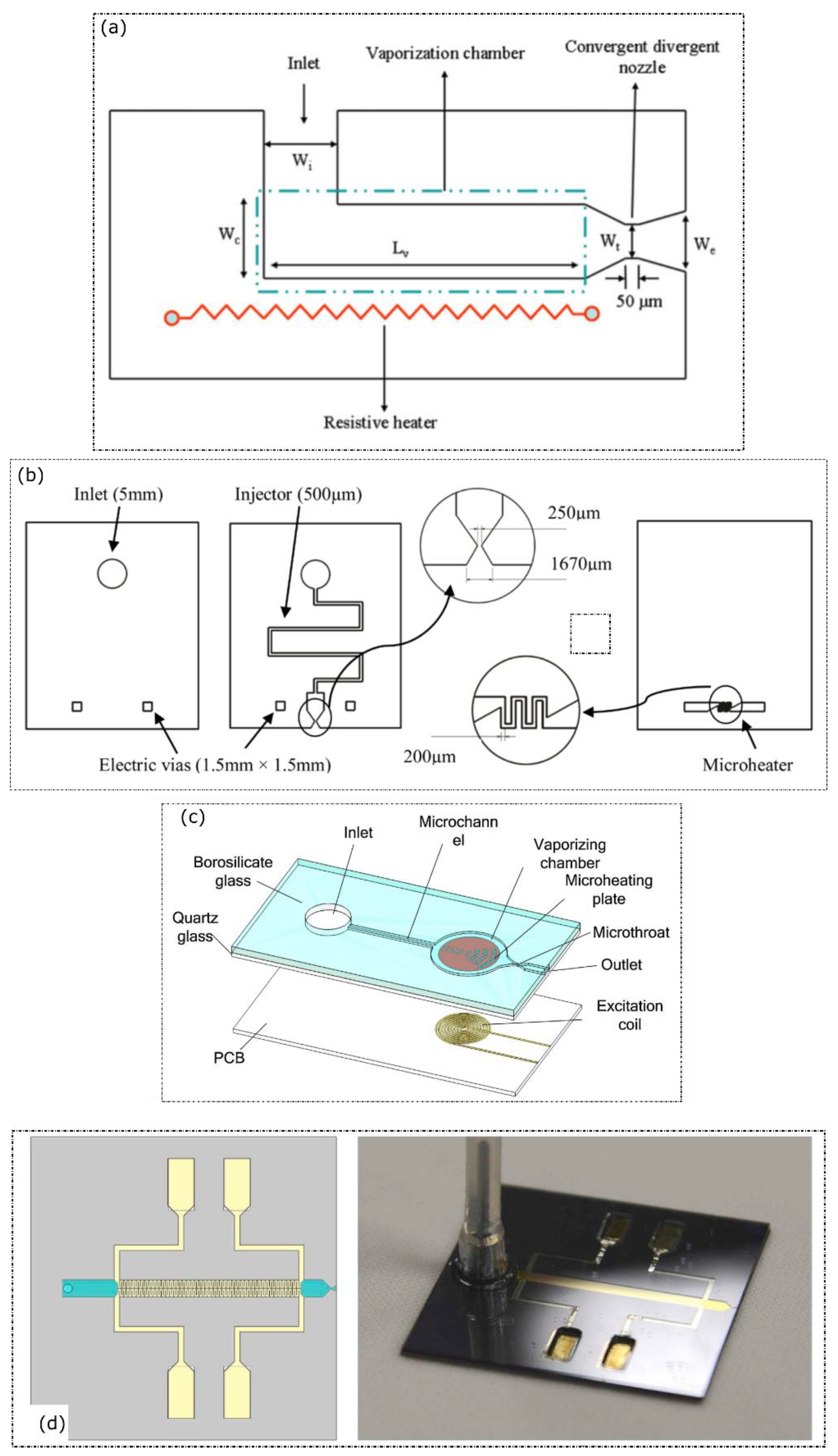
Figure 2b), measuring thrust forces in the range (5–120) μN with a heating power between 1 W and 2.4 W. Later, Kundu et al. [
14] proposed a new single-channel VLM configuration, including the use of two integrated heaters to ensure a more uniform heating (see
Figure 3a). The measured thrust force was about 1 mN using a maximum heating power of 3.6 W. Instead, Ye et al. [
15] first applied pulsed heating to a silicon-based VLM (see
Figure 3b), measuring a total impulse of
Ns produced in a second with a pulse power of 30 W. Instead, Chen et al. [
16] first performed a characterization of the two-phase heater in a single-channel VLM (see
Figure 3c), distinguishing four different flow patterns, i.e., snake flow, vapor–droplet flow, vapor–droplet–jet flow, and vapor flow.
Similarly, Cen and Xu [
17] first fabricated a MEMS-based VLM created by parallel microchannels (see
Figure 4a) and described the establishment of flow boiling instabilities in relation to the measured performance. More recently, at TU Delft (the Netherlands), Silva et al. [
18] developed a VLM with integrated molybdenum heaters (see
Figure 4b) and temperature sensing using water as a propellant; later, Pallichadath et al. [
19] described its integration on the first demonstrator of dual-mode water-propelled micro-resistojets operating in a wide range of feeding pressure for in-orbit pico-satellite applications. The launch into orbit of their PocketQube platform Delfi-PQ equipped with the VLM as a secondary propulsion system confirmed that the VLM technology reached the technology readiness level (TRL) of four.
Concerning new materials and manufacturing technologies, Karthikeyan et al. [
20] designed and manufactured a VLM using low-temperature co-fired ceramic (LTCC) as the material (see
Figure 5a), demonstrating that the LTCC is an alternative solution to silicon thanks to the good electrical conductivity of printed metallization and a relatively low production cost. Later, Cheah and Low [
21] successfully tested a high-temperature co-fired ceramic (HTCC) microthruster characterized by a platinum-based microheater integrated on a three layers structure (see
Figure 5b).
Concerning the heating system, Liu et al. [
22] developed a tubular concept of a VLM equipped with a micro-heater core, an excitation coil, a vaporizing chamber, and the micronozzle, all integrated into a glass tube with a dimension of 3 mm (outer diameter) × 18 mm (length). They conducted experiments by applying an optimal AC frequency obtaining a maximum thrust force of 680 μN at 5 mg/s. Later, Liu et al. [
23] developed a new concept of planar VLM in which the vaporization process was driven by planar induction heating (see
Figure 5d). Their microthruster consisted of a single microchannel, a micronozzle, a micro heating plate, and an external excitation coil fabricated on a PCB. Experiments showed that the device could provide a maximum thrust of 970 μN at a 5.30 mg/s mass flow rate and about 9.31 W apparent power. Instead, Kwan et al. [
24] designed an 8 W powered water-fed vaporizing liquid microthruster operating in the Leidenfrost boiling regime. As shown in
Figure 5d, the device was equipped with miniature molybdenum heating elements located inside the vaporization chamber, producing a heat flux output of 370 kW/m
2. Direct thrust measurements estimated the specific impulse and thrust level ranging between 25.9–51.1 s and 1.00–2.00 mN, respectively.
Despite the advancements described above, all VLMs have shown an intrinsically unstable behavior due to the establishment of flow boiling instabilities occurring in the inlet and the heating chambers. In this regard, Fontanarosa et al. [
25,
26] designed and fabricated a silicon-based water-propellant VLM equipped with embedded microsensors for real-time monitoring of the in-channel vapor/liquid fraction and fluid temperature during its operation (see
Figure 4c). Further, a secondary low-power platinum thin-film resistive heater was placed inside each of the eight channels, allowing for localized precision fluid heating and flow control. A preliminary characterization of the embedded sensors demonstrated the operational feasibility of the fabricated microthruster, enabling a fine heating effect localization and vaporization control.
Table 2 compares the actual propulsive performance measured during several experimental tests. It is worth observing that, from the propulsive perspective, the performance optimization of a VLM is driven by three key steps, i.e., the maximization of the thrust force
T, the maximization of the specific impulse
Isp, and the minimization of the power consumption
Pd for propellant vaporization and overheating. They were collected into the overall efficiency parameter
.
3. VLM Flow Instabilities
The behavior of the flow inside a VLM is intrinsically unstable. The pressure, temperature, and mass flow rate oscillations typically occur in the inlet and the heating chambers, caused by the establishment of flow boiling instabilities, which dramatically affecting the micronozzle’s expansion process by damaging the microthruster performance. It is worth underlining that the thrust instability created by boiling instabilities is also harmful for high-precision attitude control of micro-satellites.
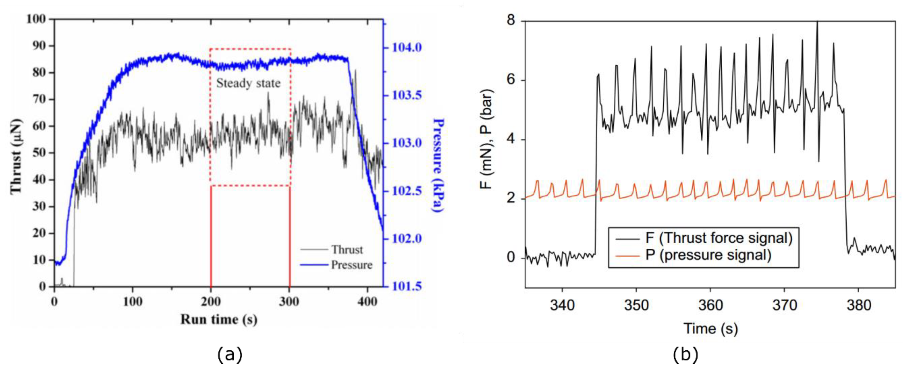
This intrinsic behavior was experimentally retrieved in all VLM designs, as confirmed in
Figure 6, where the presence of two-phase flow instabilities was revealed by the thrust and pressure signals oscillating at a similar frequency and phase angle. In particular, the feeding pressure fluctuations strongly couples with the thrust force, which oscillates at a similar frequency and phase. The higher the heating temperature and the mass flow rate are, the greater the amplitude of the oscillations becomes. On the other hand, the oscillating frequency increases as a function of the boiling number
, where
and
are the heat (in W/m
2) and mass fluxes (in kg/m
2/s), and
is the latent heat of vaporization in J/kg. Thus, a high boiling number causes significant impulse frequencies.
Few literature reviews exist on boiling flow characterization into VLMs. In [
16] and [
17] a qualitative analysis of the most characteristic flow patterns into both single-channel, and a parallel microchannels configuration is reported. In a single-channel VLM, four boiling flow regimes were observed, namely:
Snake flow. When crossing into the heating channel, the liquid water stream flows with a snake motion. At the micronozzle exit, the main fluid stream is sprayed out of the microthruster from a limited area.
Vapor–droplet flow. Large liquid droplets, flowing along the heating channel, form. These droplets are splashed out of the micro-thruster from the entire nozzle exit.
Vapor–droplet–jet flow. A vapor jet, with dispersed tiny droplets, forms as a narrow stream with concentrated vapors and tiny liquid droplets ejected from the central area of the nozzle exit.
Vapor flow. Only vapor is evenly discharged from the nozzle exit of the microthruster.
A pre-heating treatment of the empty micro-thruster at 573 K for 2 h revealed a vital step for appropriate operations of the microthruster. In this regard, the surface property changing from hydrophilicity to hydrophobicity after the heating treatment is presumed to cause snake flow disappearance.
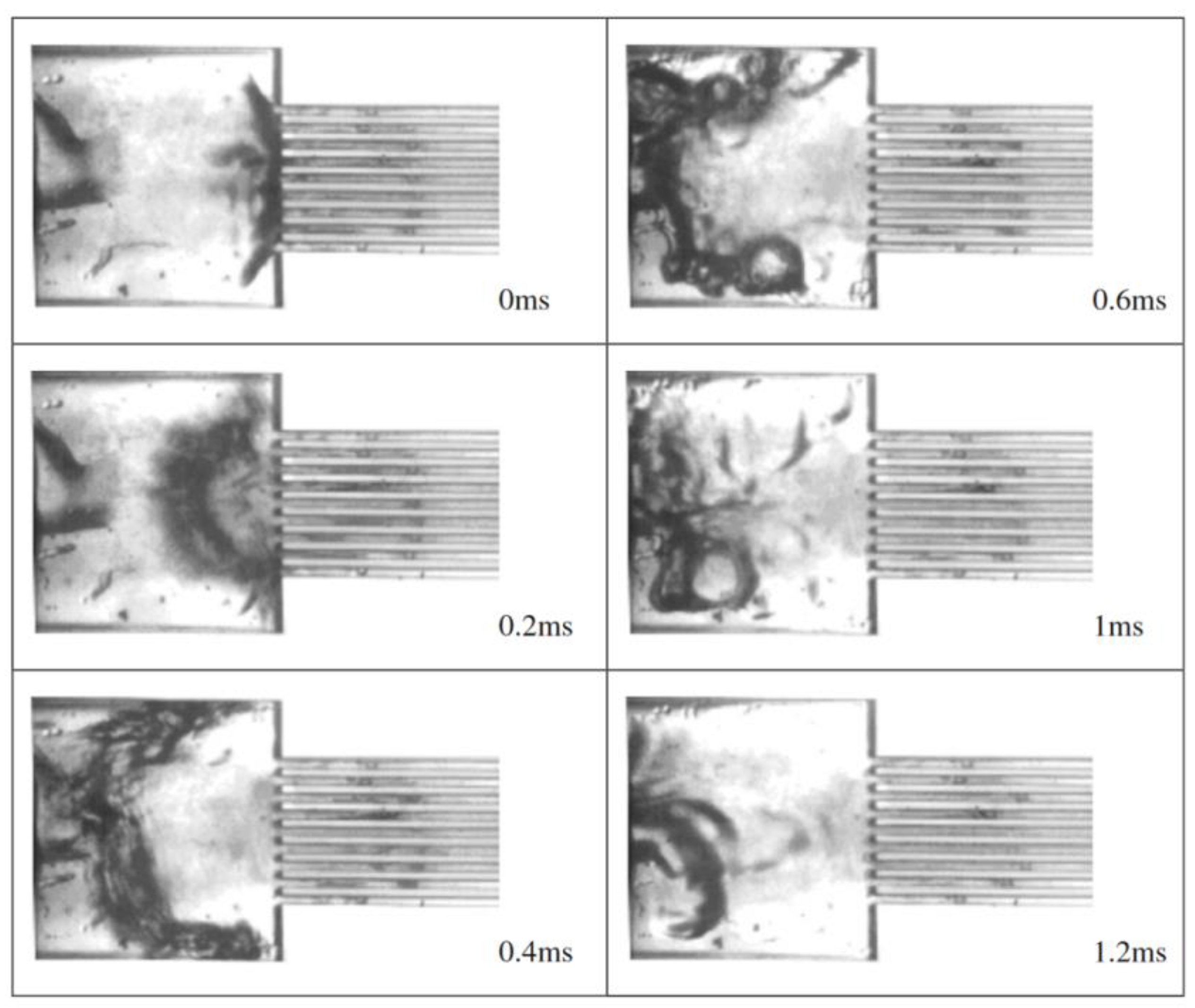
In a VLM composed of parallel microchannels, more complex two-phase flow dynamics were observed. The most significant one is the occurrence of explosive boiling phenomena (
Figure 7), experienced at occasional stained spots, in the presence of insoluble gas or tiny taints, causing rapid-bubble growth phenomena after its size exceeds a critical value or at the junction between the inlet chamber and the micro-channels where corners are sharp. When explosive boiling occurs in the microchannels, it pushes part of the incoming fluid backward. Liquid droplets move upstream towards the inlet chamber, coalesce, and clog the channel entrance. Instead, the liquid droplets going downstream the micronozzle cross the microchannels faster and with reduced residence time. Therefore, the heating process deteriorates and this results in performance losses. When explosive boiling takes place in the inlet chamber, flow reversal instability occurs in microchannels, and parallel channel instabilities are quickly established thanks to the presence of the inlet chamber. Thrust deflection occurs when the vaporization is not completed into the heating chamber, with tiny droplets asymmetrically entering the micronozzle and deflecting when the vapor bulk expands.
4. Instability Control into VLMs
Due to the intrinsically unstable behavior of VLMs, controlled or optimized operating conditions and geometrical configurations must be considered to improve the overall microthruster performance. To this purpose, their design must consider an accurate definition of their geometry for passive flow control, and more attention should also be paid to active control techniques.
In the present section, a short yet comprehensive introduction concerning the flow boiling instabilities in microchannels is provided as first (
Section 4.1), followed by the discussion of the most promising strategies for the passive (
Section 4.2) and active (
Section 4.3) control of flow boiling.
4.1. Flow Boiling Instabilities in Microchannels
Because of the more rapid growth and collapse of the vapor bubbles in a confined space, boiling in microchannels is more prone to flow instabilities than macroscale flow boiling. This causes significant pressure fluctuations, which alter the local state of the flow affecting the heat transfer process. Consequently, additional undesired effects are triggered, such as a premature critical heat flux, thermal stress, and mechanical vibration in the microchannels.
A first assessment of the confinement effect was provided in [
27], suggesting the following relation:
where
θ is the wetting angle expressed in degrees,
g0 = 9.81 m/s
2 is the gravitational acceleration
2,
and
are the liquid and vapor densities in kg/m
3, and
is the surface tension in N/m. The equation above can be used to verify whether the theoretical diameter of the bubbles is larger than the diameter of the duct and, therefore, quantify the entity of the confinement effect. Dimensionless numbers have also been proposed to indicate the relative strength of the different forces playing a key role in multiphase flows in microchannels:
Eotvos number, which measures the importance of gravity compared to the surface tension force;
Reynolds numbers , which compares inertial force to the viscous force;
Weber number , which estimates the balance between the inertial force and surface tension force;
Capillary number , which quantifies the viscous force in relation to the surface tension force.
where G is the mass flux in kg/m2/s, is the hydraulic diameter of the microchannel in m, and μ is the dynamic viscosity in Pa∙s.
When considering the Eotvos number, the possibility of the occurrence of instability increases as this one approaches zero. A new parameter was then proposed in [
28], i.e., the instability parameter
is expressed as:
where
is the backward evaporation momentum and
is the forward liquid inertia force:
In the above expressions, is the cross-section area in m2 and is the total supplied heat in W. Therefore, if is less than the unity, the flow would be stable, while a higher value of indicates that the evaporation momentum forces are dominant; thus, altering the interface movement and yielding more unstable behavior. It is worth observing that the expression of and is explicitly valid for a single channel, and they must be modified for channels with inlet restrictors or a variable cross-section. It is also worth observing that the influence of the evaporation momentum force is better evaluated by considering the density ratio in combination with the boiling number; consequently, the instability parameter includes the boiling number Bo and the liquid to vapor density ratio, since .
Flow boiling instabilities can be classified into two main groups, namely, static and dynamic instabilities. The former occurs when a disturbance to an unstable steady state drives the system to shift towards a stable, steady state; the latter generally exhibits oscillatory behavior of flow parameters such as pressure, mass flux, and temperature. If reducing the number of parallel channels and the length-to-diameter ratio enhances the static stability, dynamic instabilities involve a higher complexity. The major dynamic instabilities are bubble clogging, rapid bubble growth, flow reversal, parallel channel interaction, upstream compressibility, large inlet subcooling, and oscillating flow. An in-depth literature review of the boiling flow and its instabilities into microchannels is presented in [
29,
30].
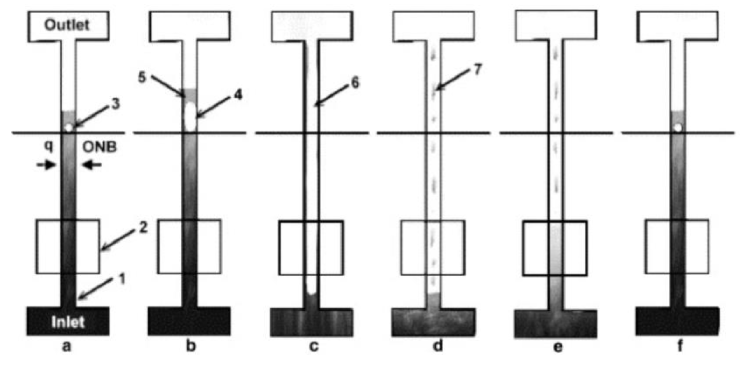
4.1.1. Bubble Clogging, Explosive Boiling and Flow Reversal
Bubbles clogging in the confined channels is one of the main sources of the inception of severe flow boiling issues. The overall process initiates from the nucleation of tiny bubbles at the various locations of the channels. Most of these bubbles condense; other ones detach from the channel wall and start to grow. If these bubbles manage to smoothly pass through the whole channels, then the flow will not be disturbed. However, if one bubble grows up to the channel size, then it blocks the passages of the incoming flow. Soon after, they become a vapor slug appearing as an elongated bubble. Typically, bubble clogging significantly depends on flow conditions, i.e., subcooled or saturated boiling and flow parameters such as mass flux, operation pressure, and inlet condition of the coolant.
When the bubble growth occurs in a very short time (below 1 s), it is well known as rapid bubble growth: it activates other flow boiling instabilities early, such as the parallel channel instability with a premature critical heat flux (CHF) occurrence, or explosive boiling phenomena with periodic wetting and dry-out, as observed in [
31].
Figure 8 describes the establishment process of the explosive boiling flow regime.
Reverse flow or backflow is also triggered by rapid bubble growth. As previously discussed, rapid bubble growth causes the rapid elongation of the upstream and downstream two-phase flow interface in the respective directions. The upstream movement of the vapor slug gives rise to a reverse flow. It is a highly undesired and dangerous phenomenon that deteriorates the heat exchange between solid walls and the flow, causing the failure of the device due to excessive thermal stress.
4.1.2. Parallel Channels Interaction during Flow Boiling Instabilities
Parallel channel interaction accelerates the adverse bubble dynamics [
32].
Figure 9 presents a simplified schematic of the bubble growth stages that originate instabilities in microchannels. Severe parallel channel instabilities start with bubble clogging followed by rapid bubble growth and the reverse flow of the vapor in the inlet section. Coupled with parallel channels interactions, upstream compressibility also triggers adverse bubble dynamics. As primary causes of dynamic instabilities in conventional devices, they result from the interaction of a boiling pressure drop with upstream compressibility, appearing due to external circuit or pump behavior. Inlet subcooling temperature Δ
Tsub,in = (
Tsat −
Tin) influences the bubble growth dynamics. In particular, the occurrence of the two-phase instabilities in microchannels accelerates as larger inlet subcooling conditions and a higher degree of wall superheat Δ
Tsup = (
Twall −
Tsat) are experienced.
In the presence of a pressure drop and flow temperature oscillations, another kind of flow boiling instability establishes, named oscillating flow. The entity of oscillations is affected by the inlet/outlet configuration of channels, the mass flux, the inlet subcooling condition, and the heat fluxes at walls. When the oscillating phenomenon involves the fluid density and an alternating appearance of the liquid flow, and two-phase vapor-liquid flow is experienced, the density wave oscillation instability occurs. In such kinds of flow boiling instabilities, the fluid density fluctuations couple with an alternating heat transfer process which affects the pressure drop along the microchannels. As a result, fluid waves of higher and lower density mixtures alternatively travel along the microchannels system.
4.2. Passive Control of Flow Instability
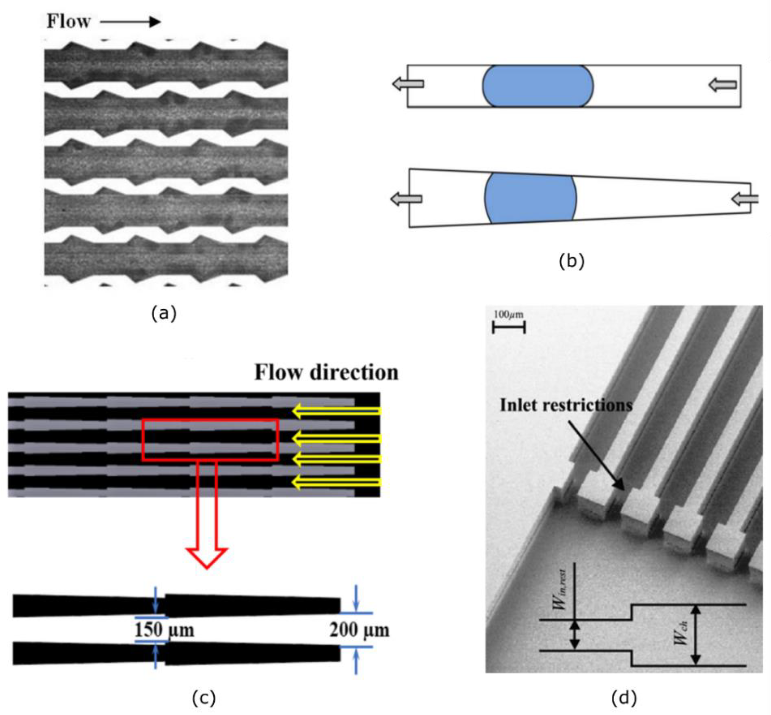
The design of the microchannel geometry is of primary importance to mitigate the flow boiling instabilities and optimize the overall thermal performance. To this purpose, several microchannel geometries have been recently investigated, such as the saw-tooth [
33], triangular [
34], and divergent [
35] microchannel geometries shown in
Figure 10. They all exhibited an enhancement in the flow boiling heat transfer, leading to mitigate flow boiling instabilities such as flow reversal and oscillating flow.
In combination with the microchannel geometry, restrictors at the microchannels inlet have successfully hindered the onset of flow reversal instabilities and the consequent establishment of parallel channel instabilities [
36,
37]. The use of artificial nucleation sites and the modification of the surface roughness and the surface porosity are also worthy of consideration for flow boiling enhancement: [
29,
30] provide an in-depth literature review on the most promising solutions to mitigate flow boiling instabilities.
It is worth underlining the further relevance of the inlet manifold geometry design: it can improve the fluid distribution between microchannels and, therefore, mitigate explosive boiling phenomena occurring into it.
4.3. Active Control of Flow Instability
The flow into VLM undergoes fast phase change phenomena in an open-loop system at high wall temperature and full vaporization conditions. An in-depth analysis of the dynamic flow instabilities is required for active control purposes, but it is still missing to date.
The dynamic analysis of two-phase oscillations (TPOs) into microchannels has always involved microchannel systems operating below the dry-out condition. As underlined in [
29,
30], TPOs into parallel microchannels systems have been mapped depending on the heat flux to mass flux (
) ratio and inlet subcooling condition. This has allowed distinguishing two main kinds of TPOs, i.e., high-frequency TPOs (above 2 Hz) and low-frequency TPOs (below 2 Hz). In particular, for a given degree of subcooling, at low
the former is experienced, characterized by a pressure drop, temperature, and mass flow rate fluctuating at low amplitudes. As
increases, the oscillating frequencies reduce, coupled with the growth of the fluctuation amplitudes, and the second TPO regime establishes.
Furthermore, it has been found that the unstable operating region of
and
extends by reducing the subcooling degree. The role of flow and thermal coupling in the presence of flow oscillations was investigated in [
38,
39] by considering a two parallel microchannels system. The first work demonstrates that controllable oscillations could benefit the mitigating flow uneven distribution and achieve a uniform temperature distribution. The second work focuses on the influence of the Ledinegg instability on the thermal performance of two thermally isolated parallel channels operating at a constant pressure and using HFE-7100 as a coolant. Results show that the boiling incipience in one of the channels triggered the Ledinegg instability due to the increased flow resistance. With an increasing heat flux, the Ledinegg instability triggered a severe uneven distribution of the flow between channels coupled with a strong temperature excursion on the flow-starved channel (experiencing boiling) owing to a deteriorated heat transfer coefficient. The temperature excursion persists until boiling occurrence in the second channel, which hinders the uneven distribution of the flow. As a result, the wall temperature of both channels reduces significantly.
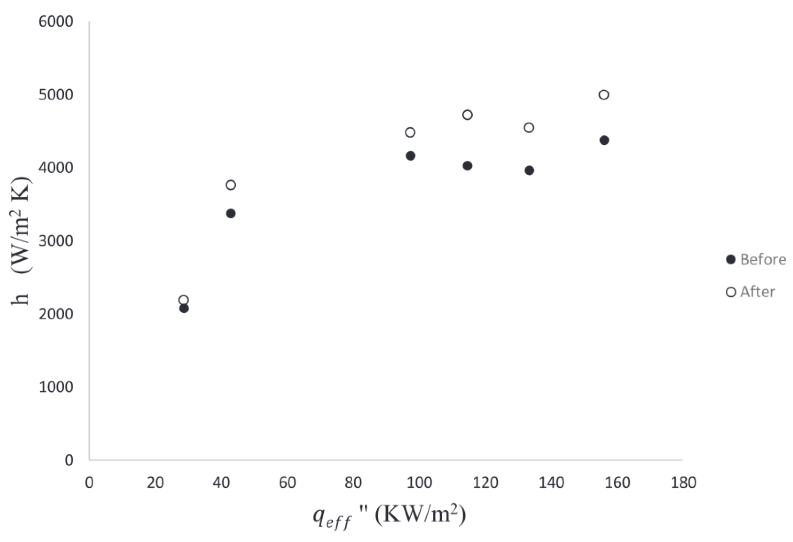
In the context described above, two main approaches were considered for the active control of flow instability. The first relies on the feeding pressure/mass flow rate control, for instance, using a micro-valving system placed upstream the inlet section [
40,
41,
42,
43], bubble seeding [
44,
45], or synthetic jet in the crossflow [
46] demonstrating the heat transfer coefficient enhancement (see
Figure 11). This approach is typically applied in partially vaporized heating systems after performing a predictive analysis of the dynamic response of the thermal system [
47]. However, oscillations of the mass flux would directly affect the propulsive performance of VLMs. Furthermore, VLMs experience the occurrence of the CHF and the dry-out condition into the heating chamber due to the need for total vaporization and overheating of the propellant flow.
The second approach of flow boiling active control focuses on heat flux-based control through the design of the heating system in combination with the temporal heating law. The interest in a pulsed heating strategy has continuously increased in recent years for thermal management applications. Miler et al. [
48] experimentally characterized transient phenomena in a water-fed single microchannel heat exchanger during pulsed heating (frequency
fs = 8 Hz and pulse duration
ts = 31 ms). The authors observed that low-frequency/high-duration pulsed heating leads to an increase in the average hotspot temperature. Similarly, Chen and Chang [
49] investigated the microscale boiling phenomenon under pulse heating (
ts = 2 ms) on a silicon-based microchannel with an integrated platinum microheater. Experiments were carried out by varying the mass and heat. Results point out that nucleate boiling gives way to film boiling as the microheater’s heat flux increases. In particular, the film boiling begins to appear on the microheater above a threshold level of the heat flux which strictly depends on the mass flux.
Another interesting experimental study was conducted to investigate heat transfer characteristics of a micro-gap heat sink under transient heat loads for flow boiling of HFE-7000 [
50], characterized by a low surface tension and high wettability. The authors found that the higher the mass flux, the more the boiling regime moves from a discrete bubble regime to a more intense boiling regime with an increasing surface temperature after boiling initiation. Instead, when increasing the heat-flux, the surface temperature rises before and after boiling onset. Furthermore, the dependency between the mass flux and the surface temperature response weakened as the pulse duration was reduced to 2 ms.
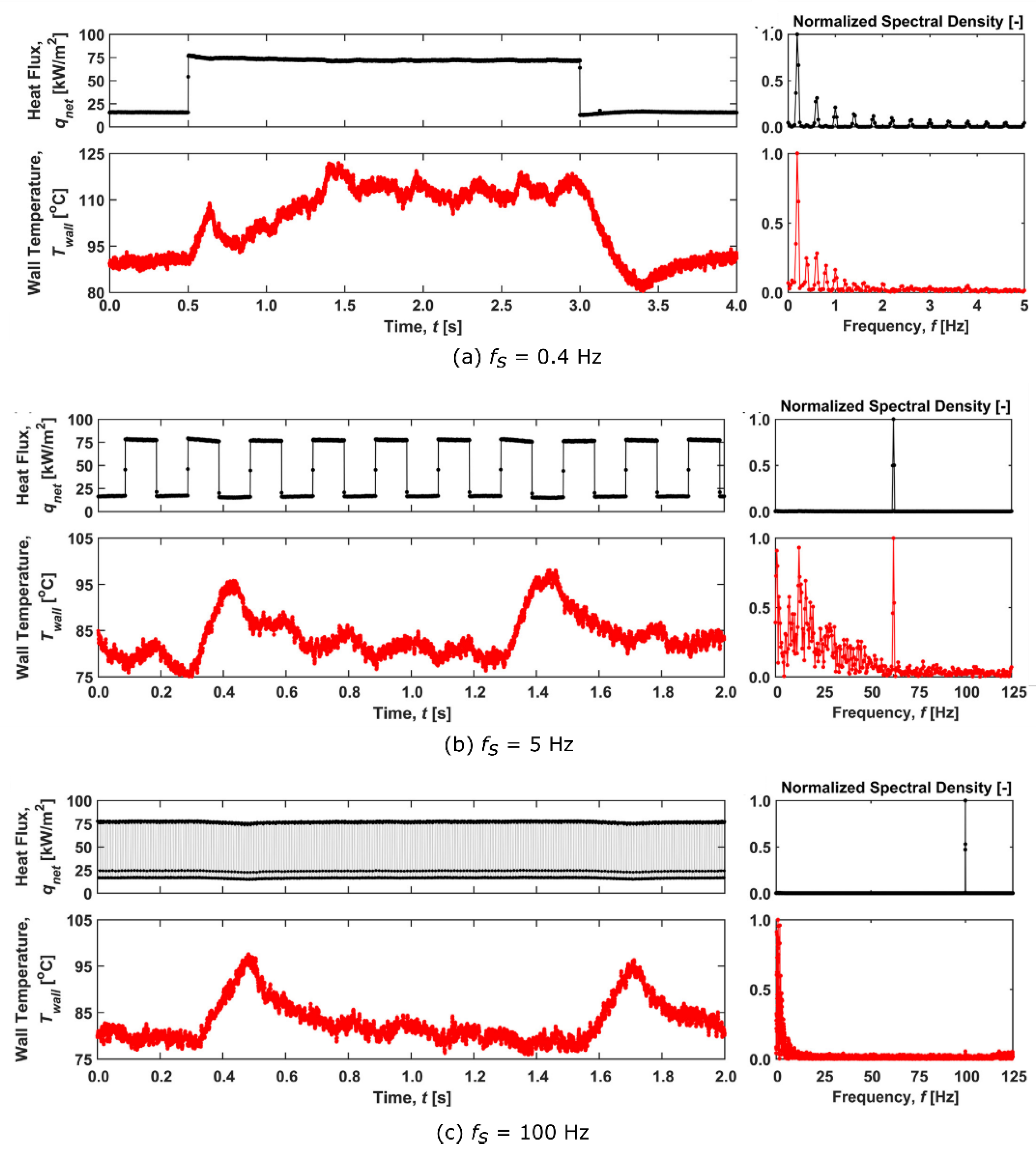
More recently, the dynamic response of a heated microchannel experiencing flow boiling of HFE-7100 in a single heat flux pulse mode was experimentally investigated in [
51]. Three heat flux levels were analyzed, corresponding to a single-phase flow, continuous two-phase flow, and above critical heat flux, respectively. Results have shown that by applying a high heat flux pulse to the microchannel after the establishment of an oscillating boiling regime, the characteristic frequency of the pressure drop instability significantly increases. Furthermore, compared to the one with a single-phase flow, the microchannel experiencing time-periodic boiling can withstand a longer high-heat flux pulse, even with the higher temperature at walls prior to the pulse. Based on these findings, a second experimental campaign was performed by applying a time-periodic series of heat flux pulses with frequencies ranging from 0.1 Hz to 100 Hz [
52]. Results show that at heating frequencies below 1 Hz (see
Figure 12a), the dynamic response consists of multiple subsequent heating steps, during each of which a new steady condition is reached. At heating frequencies ranging between 1 Hz and 10 Hz (see
Figure 12b,c), the flow boiling instabilities and performance heavily couple to the temporal profile of the heat flux, causing the pressure drop oscillation frequency to match the heating pulse frequency. Finally, at frequencies above 10 Hz (see
Figure 12c), the transient heat flux profile is attenuated, approaching continuous heating when
fs approximately exceeds 25 Hz.
5. Concluding Remarks
The present work provides a review of vaporizing liquid microthruster (VLM) technology for application to secondary propulsion systems on-board nano- and pico-satellites. The major advantages of VLMs were identified in the simplicity of their working principle, which relies on micro-resistojets operating with liquid propellants. They allow to satisfy the requirements of thrust (from a few micronewtons up to a few millinewtons), specific impulse (above 100 s), and impulse bit (ranging between nNs and mNs), in combination with light and compact propellant management systems using a microvalve system placed downstream the propellant tank to control the feeding pressure and, hence, the mass flow rate. The main drawback is the need for propellant vaporization and over-heating, which requires the integration of a heating chamber and a power cost.
An introductory analysis explored all the existing VLM concepts and their novelty, with a particular focus on the heating chamber configuration (single-channel or multiple parallel channels), the MEMS technology in terms of materials and manufacturing processes (silicon-based or ceramics-based), and the heating system (resistive heating or induction heating). The advancements experienced in the last twenty years have allowed increasing the technology readiness level (TRL) of VLMs up to four, as confirmed by the water-propelled VLM demonstrator for in-orbit pico-satellite application, designed at TU Delft and recently launched on-orbit in the PocketQube platform Delfi-PQ.
However, the actual development of VLMs has shown several limitations which jeopardize practical use on-board small spacecrafts. In fact, among all VLM concepts developed, experiments have measured τ below 0.3 mN/W and an overall efficiency parameter η0 lower than 0.2. The significant discrepancy between the theoretical performance and the real one is due to the establishment of explosive flow boiling instabilities, which reduce the heating efficiency and induce flow oscillations affecting the stability of the supersonic expansion with the occurrence of thrust instabilities and low specific impulse efficiency. The thrust instability due to boiling instabilities is harmful for high-precision attitude control of micro-satellites. Furthermore, flow boiling instability couples with the establishment of the critical heat flux condition inducing thermal stresses, which deteriorate the VLM lifetime.
Consequently, the combination of passive and active strategies for flow boiling instability control must be considered to improve the overall performance of VLMs. To this purpose, the definition of the heating chamber geometry, composed of the inlet manifold and the microchannels, is a key step in the VLM design’s optimization process. The existing literature dealing with the optimal design of micro heat exchangers has suggested different promising solutions which successfully demonstrate to mitigate flow boiling instabilities, for instance, through the use of a divergent microchannel geometry or the use of a saw-tooth and triangular microchannel, in combination with the use inlet restrictors at the microchannels entrance and/or artificial nucleation sites. Concerning the active control of flow boiling instability, the dynamic behavior of VLMs is driven by the fast phase change phenomena in an open-loop system at high wall temperature and full vaporization conditions. The classical active control approach uses the modification of the feeding pressure or the mass flow rate using a micro-valving system placed upstream of the inlet section, bubble seeding, or synthetic jet in the crossflow. An alternative control strategy is based on the active control of the heat fluxes. In this regard, the use of pulsed heating applied to micro heat exchangers operating with thermo-sensitive fluids in both single channel and double parallel channels configurations has shown promising results in terms of flow oscillations control and heating efficiency enhancement.


