Abstract
An idealized morphodynamic model is constructed for formation of the aeolian sand ripples from small bottom perturbations of a two-dimensional sand bed. The main goal of the analysis is to evaluate the influence of the gravity flow (including “impact-induced gravity flow” in the reptation flux and “topography-induced gravity flow” in the creep flux) on the formation of the aeolian sand ripples and to clarify the relative contribution of various factors to the bed instability. A 3D linear stability analysis reveals that gravity flow appreciably affects the dynamics behaviors of aeolian sand ripples, which decreases the growth rate of sand ripples, tends to stabilize the sand bed, and leads to longer wavelength. We found that the competition between the destabilizing effect of reptation flow and the stabilizing effects of gravity flow leads to pattern selection. The along-crest diffusion of topography driven by impact and gravity is beneficial to the transverse stability of sand ripples, producing sand ripples with straighter and more continuous crests. For moderate values of D, the most unstable mode has zero value of the transverse wavenumber (ky = 0), thus corresponding to aeolian ripples with crests perpendicular to the wind. Moreover, when the impact angle is 9–16°, it has little effect on the characteristics of sand ripples for the initial stage of ripple development. For every increase of the impact angle by 1°, the initial wavelength only increases by about 1.5%. In conclusion, the influence of the gravity flow on the dynamics of sand ripples formation stage cannot be neglected.
1. Introduction
Aeolian sand ripples are dynamic small-scale regular bedforms observed in sandy environments on Earth and other planets [1,2,3]. They are periodic morphological patterns with wavelengths ranging from a few centimeters to dozens of centimeters and heights of less than 1 cm, the profile of sand ripples is asymmetric. In general, aeolian sand ripples migrate, with their crests almost perpendicular to the prevailing wind direction, at a typical rate of about tens of millimeters per minute [4]. Predicting the behavior of aeolian sand ripples has practical interest because they tend to destroy farmland and cause desertification [5].
The process-based models have been developed to analyze the dynamics of aeolian sand ripples. The studies of the processes that lead to the formation of sand ripples has shown that these regular patterns arise as instabilities of the morphodynamic system describing the interaction between topography and sand transport [6,7,8,9,10,11,12].
The model of aeolian ripples can be traced back to the work of Bagnold [13], who proposed the wavelength is determined by the characteristic of saltation length. Sharp [14] found a relation between the wavelength and shear velocity, but the saltation length is larger than the wavelength. The key role of reptation in aeolian ripples formation was suggested by Anderson [6]. In short, the ripples are generated due to slope-dependent impact intensity of the saltating grains that eject reptating grains; the ripple’s lee side is then screened from the most energetic impacts, which makes the spatial differences of the reptation flux. Hoyle and Mehta [7] further considered grain rolling or avalanching under gravity. Yizhaq et al. [9] extended the continuous model to 3D structures on the sand surface, refined the reptation flux model, and predicted a saturation of ripples wavelength long term. Recently, based on direct numerical simulations, an instability mechanism leading to the formation of aeolian sand ripples was first suggested by Durán et al. [10]: resonant grain trajectories, whose length is close to the initial wavelength and whose splash causes the mass transport to the ripple crests. However, this study did not involve the later stage of ripples development. Sharp [14] suggested that the wavelength depends on the height of the sand ripples and on the impact angle of the saltation particles. When the impact angle is smaller, the shadow zone length becomes larger, producing longer sand ripples. With wind tunnel experiment and numerical simulation, Schmerler et al. [11] found that the shadow zone mechanism was more dominant in the subsequent nonlinear stage in which successive merging increased aeolian ripples. However, its relationship with the initial wavelength was not clearly demonstrated.
The gravity flow includes impact-induced gravity flow and topography-induced gravity flow, which affect the transverse instability of aeolian megaripples [15]. The impact of the topography-induced gravity flow on the contribution of aeolian bedforms has been reported by Hoyle and Metha [7], while the impact-induced gravity flow reduces the flux upslope and increases the flux downslope [15]. According to wind tunnel experiments and field observations, researchers gradually clarified the influence of wind speed and other factors on the formation and evolution of sand ripples [4,13,14,16,17,18]. The grain size distributions play an important role in determining the size of the bedform, which has been the subject of considerable investigations [13,14,16,17,19,20,21,22,23,24,25].
Although significant progress has been made both in the prediction of sand ripples formation and geometric characteristics, much remains to be done. So far, most studies have focused on the one-dimensional sand bed, that is, sand ripples are invariant in the direction transverse to the wind. However, natural sand ripples often show transverse instability [15], resulting in a 3D pattern, which has been rarely investigated [9]. Quite a few previous studies have neglected the effect of transverse sand transport on sand ripples. In addition, the effects of gravity flow on the characteristics of sand ripples are still not well involved in a process-based sand ripples model, and the relative contribution of various factors to the bed instability has not investigated systematically.
In the current study, a 3D idealized model is constructed to systematically investigate the initial stage of sand ripples formation. The model is based on the study of the linear stability of the flat sand bed. The main goal of the analysis is to evaluate influence of the gravity flow on the formation of the aeolian sand ripples and to clarify the relative contribution of various factors to the bed instability. The main innovation is to systematically analyze the above processes, including separately and in combination, then further investigate the transverse instability of the ripple crests and consider the gravity flow on dynamics of sand ripples.
2. Mathematical Model
2.1. Bed Evolution
The evolution of the sand bed is described by the mass conservation equation for the grains [6,9]:
where is the porosity of the sand bed (typically ) and is the total horizontal volumetric flux per unit width in the x- and y-directions. Equation (1) simply relates erosion/deposition processes to spatial increases/decreases of sand transport.
2.2. Sand Transport
Sand transport is the sum of three contributions: saltation, reptation, and creep. The saltating grains only provide the energy for the system and do not directly contribute to the formation of sand ripples [6,9]. We therefore assume that the saltation flux is spatially homogeneous (i.e.,).
The saltation impact causes the ejection of particles from the sand bed; the ejected particles, which have much lower energy than the saltating particles, make single small hop along the surface of the sand bed. The saltating particles are highly energetic and continue in saltation after rebounding from the sand bed [26].
We assume that the saltating particles impact the sand bed surface at an angle to the x-axis and to the y-axis (see Figure 1). The impacts cause erosion of sand bed, while the saltating grains continue to rebound from the sand bed. The erosion rate of sand grains ejected at per unit time is proportional to the impact intensity, which depends on the surface orientation with respect to the direction of saltation, based on the geometrical consideration [19,27], giving
where ,, and are the erosion rate of the grains discharged from the horizontal surface into reptation by the impacts of saltation, which are determined by the intensity of saltation. However, if the point is in shadow zone and unreachable by saltating grains, are set to zero.
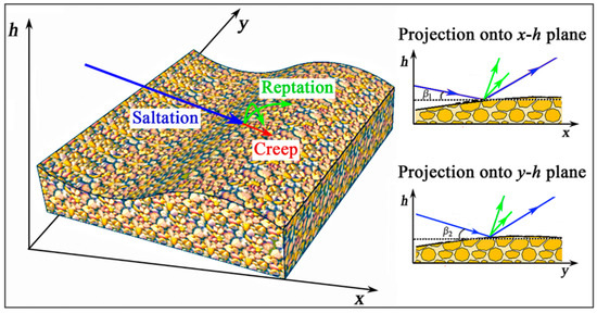
Figure 1.
Sketch of the model’s geometry.
To evaluate the reptation flux per unit width over a horizontal bed, we use the approach of Yizhaq et al. [9]; thus,
where is the probability distribution of the reptation length and is chosen from a normal distribution [19]; the parameter represents the change in the reptation flux due to the slope [9,15].
As for the creep flux of grains caused by gravity-driven, the sand grains tend to roll in the direction of steepest descent under the influence of gravity; for the three-dimensional sand ripples, the gravity-induced velocity of the sand grains can be written as [12]
where g is the acceleration of gravity and r is a function of the grain packing; in the present work, for simplicity, we set r to be constant. The horizontal creep flux of sand grains is proportional to the horizontal speed of rolling,; hence, the horizontal creep flux of grains is
where R is the equivalent partial thicknesses of the creep layer.
3. Solution Method
3.1. Scaling Procedure
To simplify the problem but also indicate the possible scenarios, we choose , , i.e., the primary transport is in the x direction and the secondary transport is in the y direction, where is the small parameter. The following dimensionless variables are introduced:
where is the mean reptation length. After dropping the tilde decoration, Equation (1) becomes:
where we have defined , and
3.2. Linear Stability Analysis
The stability of the planar sand bed is investigated by a normal mode analysis. We introduce small perturbations of the sand bed (strictly infinitesimal), hence the problem can be linearized and the small-amplitude sinusoidal topographic perturbations of the form can be considered:
where is the perturbation amplitude, is a small quantity, and is the topographic wave vector. Substituting Equation (8) into Equation (6), using the linear approximation and neglecting all nonlinear terms, keeping only the linear terms we obtain the perturbed bed evolution equation
where and are the Fourier transform of , . The solution to (9) is obtained by writing
Then, we obtain the complex growth rate of the bed perturbation as a function of the topographic wave vector; its real and imaginary parts can be written as:
The complex growth rate contains two pieces of information: the real part gives the growth or decay rate of the amplitude of perturbation (i.e., by ), and the imaginary part describes the propagation of perturbation in the space (i.e., by ). The bed is linearly stable, if the amplitudes decay for all bed perturbation modes , whereas if at least one mode bed of the amplitude grows , the bed is unstable.
In order to investigate the mechanisms responsible for the sand ripples dynamics, it is necessary to identify the various contributions to the complex growth rate. The growth rate Equation (11) consists of two contributions involving the creep flux and reptation flux in the x direction and the y direction, which depend on the slope of the bed and on the impact of saltation, respectively. It is the sum of the growth rates due to creep and reptation, according to
These contributions are given by
In turn, the reptation growth rate can be written as
This consists of the contributions due to the impact-induced reptation flow and impact-induced gravity flow . These contributions are given by:
4. Results
The values of the parameters representative of the typical sand transport conditions on Earth are considered. The thicknesses of the creep layer is related to the grain size and the number of rolling or sliding grains per unit surface, , where is the number of rolling or sliding grains per unit surface. The erosion rate is , where is the number of impacting grains per unit time and surface and is a dimensionless ejection rate coefficient. Following Durán et al. [28], the erosion rate can be expressed as , where is saltation flux and is the mean saltation length. In our model, the reptation length distribution is extracted from the study of reference [19].
We first analyze the growth rate , which depends on the creep and is negative and proportional to and ; therefore, the slope-dependence of the creep flux stabilizes short-wavelength perturbations, that is, the effect of the gravity dampens the largest wave numbers, which favors a smoothing of the bedform surface. The growth contains two contributions and ; is positive, proportional to and , and related to the probability distribution of the reptation length. The smaller the angle of impact, the larger becomes; it plays a destabilizing role. Whereas is negative and stabilizes the sand bed, it is proportional to ; the parameter represents the change in the reptation flux due to the slope effect. Physically, the saltating grain affects the sand bed and induces some grains to roll or slide down the slope. This mechanism is termed an “impact-induced gravity flow” and acts to reduce the flux upslope and to increase it downslope [15]. Hence, the pattern selection results from a compromise between the physical mechanisms of stabilizing and destabilizing. The competition between these two opposite mechanisms results in a region of amplified in the space . By changing the relative strength of these two effects, we can control the instability of the system and approximate a marginal stable state.
Figure 2 shows the growth rate of the bed perturbations as a function of the topographic wave numbers and , in which (A) the total growth rate is the sum of the contributions of (B) reptation and (C) creep. In turn, the contributions to the growth rate due to reptation are given by the sum of (D) impact-induced reptating grains flow effect, which is the growing mechanism, and (E) impact-induced gravity flow effect, which is the decaying mechanism. The results show that the reptation is the growing mechanism and the slope effect is the decaying mechanism.
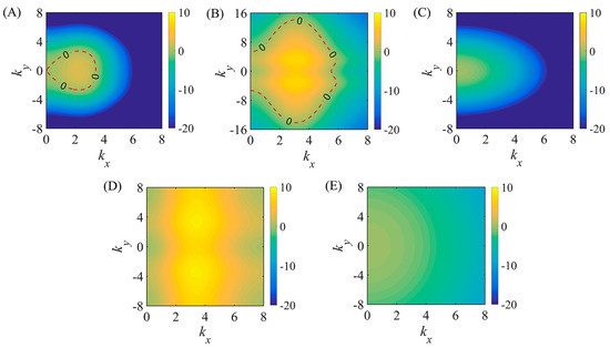
Figure 2.
The growth rate as function of the topographic wave numbers and for , , , ,, and . The total growth rate (A) is the sum of the growth rates due to reptation (B) and creep (C). The reptation growth rate is the sum of two contributions: (D) the impact-induced reptation flow and (E) the impact-induced gravity flow.
Figure 3 shows marginal stability curve of dispersion relation for different parameter , the curve where ; the other parameters are the same as in Figure 2. The curve delimits the two regions for internal and external; the sand bed is unstable in the internal area, while it is stable in the external area. The stable region expands with the increase of parameter , where is a dimensionless parameter that reflects the relative strength of reptation and creep. Taking into account that and , can be written as
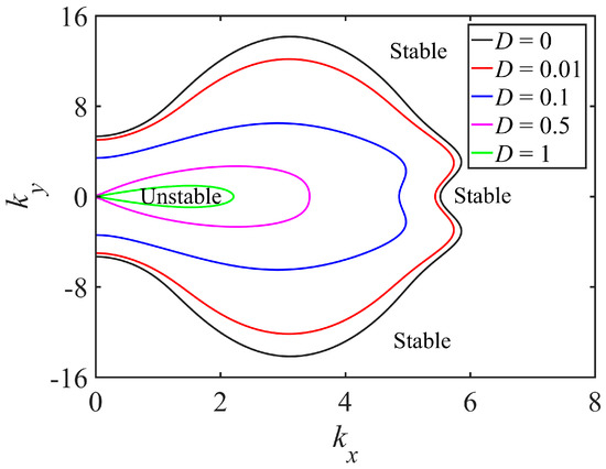
Figure 3.
Marginal stability curves for different values of D.
The numerator represents the intensity of creep transport on the inclined plane, and the denominator is the horizontal flux of reptation grains on the flat bed, so the ratio between the creep flux and the reptation flux is , in which measures the ratio of the creep flux to the reptation flux, which responsible for the relative transport intensity of the two transport modes. The next important issue is to determine the range of possible values for the model parameter D in real physical situations. Note that the experimental determination of reptation and creep is rather inadequate, especially the creep transport driven by gravity. It is therefore instructive to study the influence of these two transport modes on the marginal stability curve. In Figure 3, we find that the unstable region is very sensitive to a change of the constitutive parameter. The results show that the formation and evolution of the sand ripples occur under the combined action of saltation, reptation, and creep; the saltating grains energize the reptating population; and the gravity causes sand grain creep. So, it is proved that the instability of the sand bed is determined by the competition of the reptation and creep. For small values of , such as , the effect of the impact-induced gravity flow is much stronger than the topography–gravity flow (i.e., ); the topography-induced gravity flow is less than 1% of the flux of reptating grains, and it has almost no effect on the stability of sand ripples. Therefore, the short-wavelength stabilization originates from impact-induced gravity flow. In contrast, for large values of , the topography-induced gravity flow plays a leading stabilizing role; a band of unstable modes appears only if reptation flow prevails over topography-induced gravity flow (or more precisely, if is greater than a critical value given by , see Figure 4).
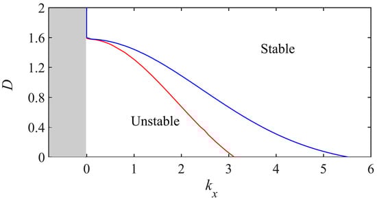
Figure 4.
Marginal stability conditions in the plane
(blue line). Red line represents the location of the relative maximum of the growth rate .
In order to efficiently investigate the effect of the parameter D on the aeolian ripples formation, a one-dimensional investigation has been made by fixing . The marginal stability conditions shown in Figure 4 were plotted in the space . The critical value Dcr of D, above which sand ripples do not appear, and sand bed stable can be easily estimated from the graph, which also shows that the sand bed becomes unstable in a finite range of wave numbers kx once D is less than its critical value. The maximum growth rate of sand bed perturbation versus its wavenumber kx for different values of D is represented by the red line shown in Figure 4. The maximum wavenumber tends to an infinitesimal value () as D tends to Dcr, and the wavelength of preferred mode tends to infinity (), so the sand bed is stable, and the sand ripples do not appear. For , the creep flux disappears; the model is similar to the model of Yizhaq et al. [9].
Figure 5 plots the contour plot of growth rate in the parameter space for different values of D. We find that the characteristics of these contour plots highly depend on the value of . The zero growth contours on the graph locate the marginal instability curve. For , the perturbation component is characterized by the maximum growth rate, i.e., the component that dominates the subsequent development of sand bed instability is characterized by (see Figure 5B). These wavenumbers correspond to the wavelength of about 2 cm. For , compared with the last case, it is clear that the instability region (i.e., regions with positive growth rates) decreases (see Figure 5C); it reflects the fact that the most unstable growth rate reaches 0.64 at . and the initial wavelength is about 4 cm. The initial wavelength scale is similar to the observed wavelengths [4] and simulates wavelengths that are about 25 times the grain diameter [10]. It is also found that the most unsble mode is longitudinal (i.e., ) and therefore corresponds to aeolian ripples having crests perpendicular to the wind. When , the instability region shrinks to a small contour, almost becoming a single point (see Figure 5D). Hence, with the increase of , the marginal instability curve asymptotically approaches a point; if continues to increase, the sand bed becomes stable and sand ripples will not be formed.
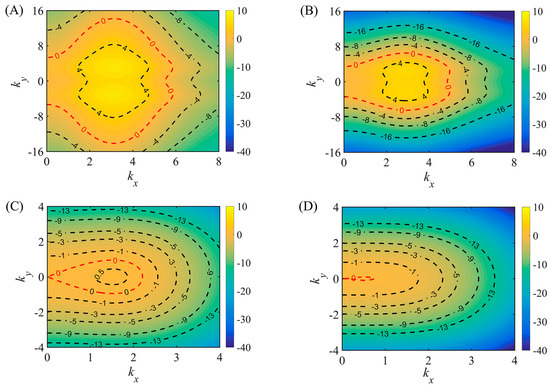
Figure 5.
The contour plot of growth rate in the parameter space for different values of D. (A) . (B) . (C) . (D) .
We investigate the effect of the impact angle for the sand ripples formation. The saltating grains typically impact the bed at angles between 9° and 16° [29,30,31]. In doing so, we fix the topographic wave vector in y direction as 0, that is, . Figure 6 shows the growth rate of the sand bed perturbations versus for different values of versus of . When the impact angle is increased, the growth rate shows that the flat sand bed is more stable. Moreover, the value of , which gives rise to the maximum value of , increases, thus showing that bigger impact angle generates longer sand ripples; the wavelength of the preferred mode increases slightly with the increase of impact angle at the initial stage (see Figure 6 (insets)). This possible reason is that the sand ripples are very small at the initial stage of sand ripple development; the greater the impact angle, the more effective the saltation impact, which will produce greater the reptation flux so that the sand ripples will grow. However, for the subsequent nonlinear growth stage, the shadow effect can be one of major mechanisms contributing to the growth of sand ripples; the smaller the impact angle, the larger the shadow zone and the longer the wavelength [11,14]. The influence of impact angle on the dynamics of sand ripples is different in the initial linear stage and the later nonlinear stage. It remains for future further studies to determine the influence of impact angle in different stages of ripples formation.
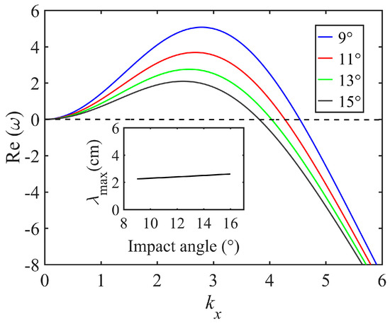
Figure 6.
The growth rate plotted versus the wavenumber , fixing for different impact angle. The insets show the wavelength of the preferred mode as function of the impact angle.
It is interesting to discuss the unstable transverse mode, although the mode does not prevail in the linear regime; since its growth rate is smaller than that of the preferred mode, we may wonder whether they play an important role in the transverse development of sand ripples. The influence of topography-induced gravity transport on the transverse instability is illustrated in Figure 7A; it shows that for small values of (for example ), a wavy crestline with finite wavelength is formed, which corresponds to the most unstable mode . This is the early stage of sand ripple formation, and the ripples are small (i.e., D is small), so the lateral transport of gravity flow is small, which reduces the lateral coupling and produces sand ripples with more irregular and lateral instability. This is consistent with the characteristics of the early formation stage of sand ripple observed in wind tunnel and field. With the increase of D, most unstable transverse mode is . For example, when , we get . It reflects that the most unstable mode is a longitudinal mode in both modes; thus, the corresponding sand ripples has more straight and continuous crests perpendicular to the wind direction. In fact, as the sand ripples grow, the gravity flow increases (i.e., increases). The lateral transport of gravity flow has the capability of reducing along-crest topographic irregularities and producing sand ripples with straighter and more continuous crests perpendicular to the wind. This is also consistent with the features observed in wind tunnels and field. Figure 7B plots the growth rate versus for for different values of ; it shows similar results, where measures the strength of the sand flux by impact-driven along the y direction, which is responsible for the lateral coupling [15]. A larger lateral (along-crest) sand transport tends to stabilize the transverse mode, and the wavelength of the transverse mode becomes larger, which has the capability of reducing along-crest topographic instability and irregularities and producing bedform-like structures with straighter and more continuous crests. The numerical simulations of Yizhaq et al. [15] support our analysis results that owing to the large lateral flux, the along-crest height of sand ripples is almost the same; the transverse tends to be stable, reducing along-crest ripples sinuosity, creating a straighter crestline. In fact, the aeolian sand ripples are generally straight and continuous, which requires the physical coupling process along the crest of the sand ripples, and that lateral (along-crest) sand transport provides effective physical mechanisms to couple the topography at different along-crest locations and to overcome local instability. In the proposed model, the lateral transport is mainly contributed to by the along-crest diffusion of topography driven by impact and gravity; with the increase of and , the lateral transport increases, which provides a mechanism for extending sand ripples in the along-crest direction. The normal ripples composed of monodisperse fine sand particles have larger transverse transport, which can fill downwind concavities and flatten downwind convexities; the sand ripple is straight and continuous [32]. However, for megaripples, coarse particles accumulate at the crest, which reduces the lateral sand transport along the ripple crest and increases the irregularities and transverse instability along-crest [15]. The transverse aeolian dunes are not straight, while the origin of transverse instability is due to different drift velocities caused by the different heights along the cross-wind direction [33] and due to the fact that the lateral transport on the dune slip face prevails over that on the upwind face [34]. This difference may arise from the strong scale separation between the grains’ average hop length and the typical size of the dune, while there is no such scale separation for smaller-scale sand ripples. The transverse modes do not grow as fast as the longitudinal modes in the linear regime, but they could couple each other in the nonlinear regime. A further nonlinear analysis should be made to investigate the interaction between different modes and predict the defect behavior and bedform straightening in the non-transverse cases.
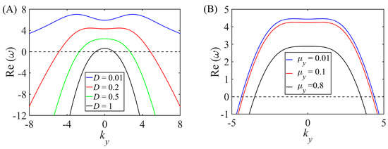
Figure 7.
The growth rate for different (A) and (B) versus for .
5. Discussion
Aeolian sand ripple is a typical geomorphic type resulting from the interaction between topography and sediment transport, which is mainly caused by the impact on a sand bed of saltating grains entrained by the wind. In this work, we propose an ideal model to systematically investigate influence of the gravity flow on the formation of the aeolian sand ripples, to discuss the lateral stability of sand ripples and to clarify the relative contribution of various factors to the bed instability; this is rarely seen in the existing theoretical model. Based on grain-scale simulations, Durán et al. [10] argued that the instability is driven by resonant grain trajectories with a distance close to the initial ripple wavelength, and the stability effect originates from the slope-dependent sand transport. However, it was not clearly explained how the stabilizing is related to the phase-locking caused by particles jumping from one crest to another, and the lateral stability of sand ripple is not involved. In this work, we discussed the stability mechanism through the diffusion transport of gravity flow and analyzed the influence of gravity flow on the formation of sand ripples. We found that the lateral gravity flow provides effective physical mechanisms to overcome local transverse instability and to produce straight crests. However, due to the assumption that the space of saltation flux is uniform in continuous model, the model has some limitations. The present 3-D model is based on the linear stability stable analysis; it cannot be used to investigate the saturated amplitude attained by the growing perturbation for the later stage. Indeed, with the growth of sand ripples and reach large values, nonlinear effects become strong and the linear analysis fails. It remains for future studies to investigate the nonlinear regime.
6. Conclusions
We have developed a new idealized 3D aeolian sand ripples model that is able to systematically investigate gravity flow and other factors related to processes in aeolian ripples dynamics in the formation stage. We found that gravity flow (including “impact-induced gravity flow” and “topography-induced gravity flow”) decreases the growth rate of sand ripples significantly. The impact-driven reptation flow has a destabilizing effect, while the gravity flow tends to stabilize the sand bed and leads to longer wavelength. On the other hand, when the impact angle is increased from 9° to 15°, the initial wavelength is increased by only 0.2 cm, which means the impact angle has little effect on the characteristics of sand ripples at the initial stage of ripple development. The lateral gravity flow provides effective physical mechanisms to overcome local transverse instability and to produce straight crests. Finally, the results show that the relative transport intensity of the two transport modes essentially effects the instability of sand bed and consequently affects the formation of sand ripples.
The model provides a simplified description of the actual phenomenon in the sand ripples formation; however, it takes into account the main processes that affect the formation of sand ripples (e.g., saltation, reptation, and creep). This ideal model is, of course, far from natural situations; however, we expect to gain an improved understanding of the instability mechanisms of the three-dimensional bedforms. Indeed, this can be considered as a canonical situation. In the future, some aspects need to be further improved. For example, a better model capable of describing the mesoscale structure of aeolian sand transport could be introduced to study the effects of wind speed on the behavior of aeolian sand ripples, to overcome the shortcomings of the existing continuous model that cannot describe the dependence of the wavelength on wind speed.
Author Contributions
P.W. contributed to the conception and design of the study. P.W., N.H. and J.Z. performed analyses of the results and wrote the manuscript. All authors have read and agreed to the published version of the manuscript.
Funding
This research was funded by the State Key Program of National Natural Science Foundation of China OF FUNDER, grant number 41931179, and the National Natural Foundation of China OF FUNDER, grant number 42161002 and 12064034, and the Fundamental Research Funds for the Central Universities OF FUNDER, grant number lzujbky-2020-cd06, the Natural Science Foundation of Gansu Province OF FUNDER, grant number 21JR7RA244.
Institutional Review Board Statement
This study did not involve humans or animals.
Informed Consent Statement
This study did not involve humans.
Data Availability Statement
This study did not report any data.
Conflicts of Interest
The authors declare no conflict of interest.
References
- Kok, J.F.; Parteli, E.J.; Michaels, T.I.; Karam, D.B. The physics of wind-blown sand and dust. Rep. Prog. Phys. 2012, 75, 106901. [Google Scholar] [CrossRef] [Green Version]
- Yizhaq, H.; Kok, J.; Katra, I. Basaltic sand ripples at Eagle Crater as indirect evidence for the hysteresis effect in martian saltation. Icarus 2014, 230, 143–150. [Google Scholar] [CrossRef]
- Sullivan, R.; Kok, J.; Katra, I.; Yizhaq, H. A broad continuum of aeolian impact ripple morphologies on Mars is enabled by low wind dynamic pressures. J. Geophys. Res. Planets 2020, 125, e2020JE006485. [Google Scholar] [CrossRef]
- Andreotti, B.; Claudin, P.; Pouliquen, O. Aeolian Sand Ripples: Experimental Study of Fully Developed States. Phys. Rev. Lett. 2006, 96, 028001. [Google Scholar] [CrossRef] [Green Version]
- Shao, Y. Physics and Modelling of Wind Erosion; Kluwer Academic Publishers: Boston, MA, USA, 2000. [Google Scholar]
- Anderson, R.S. A theoretical model for aeolian impact ripples. Sedimentology 1987, 34, 943–956. [Google Scholar] [CrossRef]
- Hoyle, R.B.; Mehta, A. Two-Species Continuum Model for Aeolian Sand Ripples. Phys. Rev. Lett. 1999, 83, 5170–5173. [Google Scholar] [CrossRef] [Green Version]
- Prigozhin, L. Nonlinear dynamics of Aeolian sand ripples. Phys. Rev. E 1999, 60, 729–733. [Google Scholar] [CrossRef] [PubMed] [Green Version]
- Yizhaq, H.; Balmforth, N.J.; Provenzale, A. Blown by wind: Nonlinear dynamics of aeolian sand ripples. Phys. D 2004, 195, 207–228. [Google Scholar] [CrossRef]
- Durán, O.; Claudin, P.; Andreotti, B. Direct numerical simulations of aeolian sand ripples. Proc. Natl. Acad. Sci. USA 2014, 111, 15665. [Google Scholar] [CrossRef] [Green Version]
- Schmerler, E.; Katra, I.; Kok, J.F.; Tsoar, H.; Yizhaq, H. Experimental and numerical study of Sharp’s shadow zone hypothesis on sand ripple wavelength. Aeolian Res. 2016, 22, 37–46. [Google Scholar] [CrossRef]
- Csahók, Z.; Misbah, C.; Rioual, F.; Valance, A. Dynamics of aeolian sand ripples. Eur. Phys. J. E 2000, 3, 71–86. [Google Scholar] [CrossRef] [Green Version]
- Bagnold, R. The Physics of Blown Sand and Desert Dunes; Dover Publication: Mineola, NY, USA, 1941; 265p. [Google Scholar]
- Sharp, R.P. Wind Ripples. J. Geol. 1963, 71, 617–636. [Google Scholar] [CrossRef]
- Yizhaq, H.; Bel, G.; Silvestro, S.; Elperin, T.; Kok, J.; Cardinale, M.; Provenzale, A.; Katra, I. The origin of the transverse instability of aeolian megaripples. Earth Planet. Sci. Lett. 2019, 512, 59–70. [Google Scholar] [CrossRef]
- Seppälä, M.; Lindé, K. Wind tunnel studies of ripple formation. Geogr. Ann. Ser. A Phys. Geogr. 1978, 60, 29–42. [Google Scholar] [CrossRef]
- Rasmussen, K.R.; Valance, A.; Merrison, J. Laboratory studies of aeolian sediment transport processes on planetary surfaces. Geomorphology 2015, 244, 74–94. [Google Scholar] [CrossRef]
- Cheng, H.; Liu, C.; Li, J.; Liu, B.; Zheng, Z.; Zou, X.; Kang, L.; Fang, Y. Experimental study of aeolian sand ripples in a wind tunnel. Earth Surf. Process. Landf. 2018, 43, 312–321. [Google Scholar] [CrossRef]
- Manukyan, E.; Prigozhin, L. Formation of aeolian ripples and sand sorting. Phys. Rev. E 2009, 79, 031303. [Google Scholar] [CrossRef] [Green Version]
- Yizhaq, H.; Katra, I.; Isenberg, O.; Tsoar, H. Evolution of megaripples from a flat bed. Aeolian Res. 2012, 6, 1–12. [Google Scholar] [CrossRef]
- Katra, I.; Yizhaq, H.; Kok, J.F. Mechanisms limiting the growth of aeolian megaripples. Geophys. Res. Lett. 2014, 41, 858–865. [Google Scholar] [CrossRef]
- Yizhaq, H.; Katra, I. Longevity of aeolian megaripples. Earth Planet. Sci. Lett. 2015, 422, 28–32. [Google Scholar] [CrossRef]
- McKenna Neuman, C.; Bédard, o. A wind tunnel investigation of particle segregation, ripple formation and armouring within sand beds of systematically varied texture. Earth Surf. Process. Landf. 2017, 42, 749–762. [Google Scholar] [CrossRef]
- Lämmel, M.; Meiwald, A.; Yizhaq, H.; Tsoar, H.; Katra, I.; Kroy, K. Aeolian sand sorting and megaripple formation. Nat. Phys. 2018, 14, 759–765. [Google Scholar] [CrossRef]
- Wang, P.; Zhang, J.; Huang, N. A theoretical model for aeolian polydisperse-sand ripples. Geomorphology 2019, 335, 28–36. [Google Scholar] [CrossRef]
- Lämmel, M.; Rings, D.; Kroy, K. A two-species continuum model for aeolian sand transport. New J. Phys. 2012, 14, 093037. [Google Scholar] [CrossRef]
- Siminovich, A.; Elperin, T.; Katra, I.; Kok, J.; Sullivan, R.; Silvestro, S.; Yizhaq, H. Numerical study of shear stress distribution over sand ripples under terrestrial and Martian conditions. J. Geophys. Res. Planets 2019, 124, 175–185. [Google Scholar] [CrossRef]
- Durán, O.; Claudin, P.; Andreotti, B. On aeolian transport: Grain-scale interactions, dynamical mechanisms and scaling laws. Aeolian Res. 2011, 3, 243–270. [Google Scholar] [CrossRef]
- Willetts, B.; Rice, M. Collisions of quartz grains with a sand bed: The influence of incident angle. Earth Surf. Process. Landf. 1989, 14, 719–730. [Google Scholar] [CrossRef]
- Nalpanis, P.; Hunt, J.; Barrett, C. Saltating particles over flat beds. J. Fluid Mech. 1993, 251, 661–685. [Google Scholar] [CrossRef]
- Swann, C.; Sherman, D. A bedload trap for aeolian sand transport. Aeolian Res. 2013, 11, 61–66. [Google Scholar] [CrossRef]
- Rubin, D.M. A unifying model for planform straightness of ripples and dunes in air and water. Earth Sci. Rev. 2012, 113, 176–185. [Google Scholar] [CrossRef] [Green Version]
- Parteli, E.J.; Andrade, J.S., Jr.; Herrmann, H.J. Transverse instability of dunes. Phys. Rev. Lett. 2011, 107, 188001. [Google Scholar] [CrossRef] [PubMed] [Green Version]
- Guignier, L.; Niiya, H.; Nishimori, H.; Lague, D.; Valance, A. Sand dunes as migrating strings. Phys. Rev. E 2013, 87, 052206. [Google Scholar] [CrossRef] [PubMed]
Publisher’s Note: MDPI stays neutral with regard to jurisdictional claims in published maps and institutional affiliations. |
© 2021 by the authors. Licensee MDPI, Basel, Switzerland. This article is an open access article distributed under the terms and conditions of the Creative Commons Attribution (CC BY) license (https://creativecommons.org/licenses/by/4.0/).