Article

Barrier Function Based Adaptive Sliding Mode Controller for a Hybrid AC/DC Microgrid Involving Multiple Renewables

1
Department of Electrical Engineering, Jouf University, Sakaka 72388, Saudi Arabia
2
School of Electrical Engineering Technology, The University of Faisalabad (TUF), Faisalabad 38000, Pakistan
3
School of Electrical Engineering, Shandong University, Jinan 250061, China
4
School of Electrical Engineering and Computer Science (SEECS), National University of Sciences and Technology (NUST), Islamabad 44000, Pakistan
*
Author to whom correspondence should be addressed.
Appl. Sci. 2021, 11(18), 8672; https://doi.org/10.3390/app11188672
Submission received: 22 August 2021 / Revised: 10 September 2021 / Accepted: 10 September 2021 / Published: 17 September 2021
(This article belongs to the Special Issue Advanced Solar–Wind–Hydro Hybrid Energy System)

Abstract

:
Conventional electricity generation methods are under the major revolution, and microgrids established on renewable energy sources are playing a vital role in this power generation transformation. This study proposes a hybrid AC/DC microgrid with a barrier function-based adaptive sliding mode controller, in which 8 kW wind energy system and 4.5 kW photovoltaic energy system perform as the hybrid RESs, and 33 Ah of battery works as the energy storage system. Barrier function-based adaptive sliding mode controller ensures the convergence of the system’s output variable independent of the knowledge of the upper bound of the disturbances. Firstly, global mathematical modeling of the suggested system is ensured. Then, the control laws are defined, providing the DC bus voltage regulation during islanding mode and AC/DC link bus voltage regulation during the grid-connected mode. The proposed barrier function-based adaptive sliding mode controller technique is analyzed through 20 s simulations on MATLAB/Simulink, which validates the controller’s robustness and effectiveness. Furthermore, a comparison of the proposed controller is made with the proportional integral derivative controller, Lyapunov controller, and sliding mode controller. In the end, hardware-in-loop tests are performed using C2000 Delfino MCU F28379D LaunchPad, showing the proposed structure’s real-time performance.

1. Introduction

During the past few years, the generation of electricity through conventional energy sources is raising major environmental concerns because of the greenhouse effect and other pollutants [1]. Various methods have been introduced to combat environmental pollution and climate change. One of the significant ways is to implement a renewable energy sources (RESs)-based microgrid, due to its high efficiency and simplicity, and that it has played a vital role in clean energy generation [2,3]. Moreover, increasing consumption of RESs in microgrid development has significant concerns about power balance and stable frequency due to the unpredictable environmental effects on RESs. Therefore, they are not preferred to be implemented alone; hence, the energy storage system’s (ESS) integration is preferred [3,4].
Renewable sources, either photovoltaic (PV) or wind, are used in distribution generation (DG) systems in microgrids mostly. However, a combination of PV and wind is proposed in [5,6], which increases energy flow towards the utility grid and enhances the overall stability. It is observed that DG systems with two or more RESs present complementary nature and reduces the sizing of the energy storage elements [7]. Mostly battery banks and ultra-capacitors are integrated with microgrid as energy storage system (ESS) and ensure the steady flow of power [8,9].
In recent years, hybrid AC/DC microgrid-based solutions have gained popularity in the DG system by integrating renewable sources [10,11,12]. Typically, AC/DC microgrid consists of AC and DC sub-grid and interconnected via power converters. This type of model provides the merits of both DC microgrid and AC microgrid [6]. It can facilitate the AC and DC loads by avoiding multi-conversion processes, which increase the overall energy efficiency [13]. A hybrid PV and wind energy system with ESS is studied in [14]. The framework of the proposed system contains multiple converters attached with the RESs and ESS to the common DC bus. However, it does not guarantee stability, uses the hit and trial method to optimize the solution, and several tuning parameters are compulsory. The paper [15] presents a RESs based microgrid functioning in a grid-connected mode. Such a type of system involves difficult control procedures and demands extreme operating conditions among the power converters. Ref. [16] presents the wind, PV, and ESS model connected with AC loads via back-to-back converters. PV system design can be operated in maximum power point tracking (MPPT) mode and off-MPPT mode, and the battery supports the power balance at the DC bus. The coordinate linear control technique is used in the paper, and it does not compensate for the non-linear attributes of the power circuitry used in the model [17].
Transfer of power with quality, efficiency, and stability are the key requirements in any system and different energy management techniques, and composite control process is inevitable in the microgrid. Different control techniques to stabilize the common DC bus have been proposed in [18,19,20,21]. Some studies [22,23,24,25,26] suggest some control techniques for power managing framework in AC microgrids. However, the hybrid AC/DC microgrid performs synthesis operation to aim the control and optimization of DC subgrid and AC subgrid [27]. Hence, these techniques are not directly applicable to hybrid AC/DC microgrids. Many studies provide the control techniques for the hybrid AC/DC microgrids. The proposed model in [28] operates in islanded mode and grid-connected mode. An inverter ensures the stable voltage and frequency at the AC subgrid, and the converter regulates the voltage at the DC common bus under the islanding operation of microgrid. During the grid-connected mode, the AC subgrid maintains its stable voltage and frequency, acting as a finite bus. Therefore, the objective to be aimed is the DC common bus stabilization, which is performed by the DC–DC converters. In [29,30], other control techniques have also been applied on a similar framework but the unpredictable nature of RESs is not taken into consideration.
Various linear control schemes, aiming to achieve the voltage stability at DC bus, have been proposed in [20,31,32], however, suggested methods mostly discard the non-linear features of DC–DC converters, and control exertion will restrict to a smaller region. Ref. [19] suggests a robust H controller to address the restraints by assuming the uncertainties at the load; however, stability analysis is not ensured rigorously. The droop control method is frequently applied for DC bus voltage regulation, and [33] proposed the adaptive droop control, but communication delay occurs when multiple sources, such as wind system, PV system, and ESSs, are connected. In [34], an interlinked AC and DC subgrid model is proposed to implement the coordinate controller. However, the proposed model does not consider the intermittency of RESs in the structure. Moreover, it results in voltage fluctuation in the presence of multiple energy sources. Some additional linear control methods are proposed in [16,33,35,36], but the behavior of RESs with power converters and ESS is not modeled. The literature discussed so far shows that substantial work has been performed to ensure the stability of DC and AC bus voltage of the microgrid. Typically, linear control methods were presented. However, the uncertain behavior of RESs exhibits dynamic operating regions for microgrid’s operation. Therefore, performance inadequacy occurs for linear controllers to mitigate the fast transients, e.g., sudden cut-off at generation end, the quick change in load, etc.
Some non-linear control methods for hybrid AC/DC microgrids are presented in [18,28,37]. In [18], the proposed hybrid AC/DC microgrid offers integral terminal sliding mode control for the machine side and grid side for on-grid and off-grid mode. The stable voltage at the AC and DC bus is achieved under different weather conditions but due to the presence of hybrid RES and hybrid ESS, the intricacy of the system increases. Ref. [18] offers an integral back-stepping based non-linear control which ensures the regulation of the DC bus. However, the proposed model only operates in islanding mode. Moreover, two control techniques are integrated which causes involvedness. Ref. [38] presents a hybrid AC/DC microgrid directly connected with the grid without considering any ESS in the system. A non-linear sliding mode controller has been proposed in [21,39] to achieve DC bus voltage regulation, but the controller has limitations as it shows chattering and less profound to external disturbances. A recent study, Ref. [40], provides a double integral sliding mode controller to address the chattering and external disturbances issues. However, this study only considers the DC microgrid with a hybrid energy storage system and ensures energy management and tight DC bus voltage regulation. In [41], an adaptive Lyapunov redesign approach is suggested for power converters associated with renewable sources and hybrid energy storage systems considering the model uncertainties in the system. It guarantees the DC voltage regulation and energy management in the system but does not consider any DC–AC inverter in the system. In [42], Lyapunov-based non-linear control for RESs has been proposed where it provides the secondary support to AC subgrid during the on-grid mode by ensuring frequency, voltage, and power system stabilization.
Keeping in view all the problems mentioned above, it is evident that hybrid AC/DC microgrid having different distributed generators, energy storage elements, and AC/DC loads are always challenging work. The unpredicted behavior of RESs under changing weather conditions drastically affects the stability of the grid [18]. Moreover, the constant power loads (CPL) at the DC side of the grid degrades the performance of the system [42]. Furthermore, when two modes of the MG are offered in the model then switching between the islanding and grid-connected mode will fluctuate the DC and AC bus which can be devastating for the power system. Hence, a more accurate, adaptive, and efficient control law is compulsory for the stability of the microgrid under capricious generation, loads demand, and operating conditions. Therefore, this work proposes a barrier function-based adaptive sliding mode (BFASMC) controller for hybrid renewable energy sources based AC/DC microgrid with an energy storage system. Simple SMC and Lyapunov controllers are not preferred because the hit and trial method is used to tune their parameters which may cause chattering and fluctuations in its operation and shows high transient values during initial and varying conditions which are not admissible in the MG system. Double integral SMC eliminates the chattering issue but still shows high transients, and during the switching between the modes of the MG, there may occur huge oscillations at the DC and AC bus. The integral back-stepping controller becomes very complex due to the virtual controller’s introduction, and there may come computational restrictions for multiple DGs. Therefore, a barrier function-based adaptive SMC is proposed which offers simple structure, chattering free operation, adaptive nature, enhanced robustness to different disturbances, the inessential limit of upper-bound uncertainties, and better performance than exiting controllers and, also, this technique is not implemented on such models before. The adaptive behavior of the controller will cause fewer transients during the mode switching of the MG. Figure 1 reveals the proposed hybrid AC/DC microgrid model. It carries a wind energy system (WES), PV panels stack, energy storage system (battery), a common AC/DC bus, and AC/DC loads. The wind energy unit is comprised of a wind turbine attached with PMSG, and its output is forwarded to the bridge rectifier, and then a DC–DC boost converter connects the system with a DC-link bus. The PV stack connects with the DC-link bus via a non-inverting buck-boost converter. Additionally, the battery as an energy storage unit connects with the DC bus via a buck-boost converter. The control unit is divided into two parts.
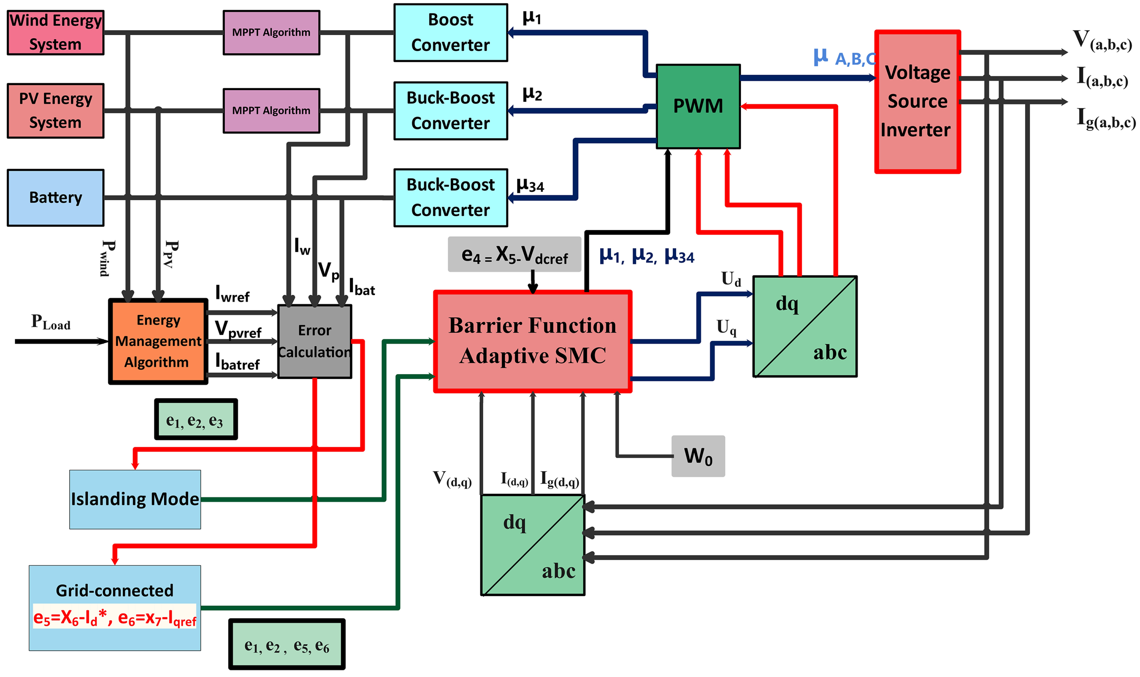
  • Low-Level Control: It ensures the regulation of input and output current flow from power converters referred to their reference signals produced by the high-level controller;
  • High-Level Control: It ensures the AC/DC microgrid’s stability by monitoring the state of charge (SoC).
In this research work, common AC and DC bus voltage regulation under load varying conditions, external disturbances or uncertainties, and impulsiveness of RES are studied. Furthermore, the practical performance of the controller’s efficiency is validated using real-time hardware-in-loop analysis. This study offers the following significant contributions:
  • Multiple control laws to ensure the stability of the DC bus and AC bus under the load varying conditions, external disturbances, and impulsiveness of RESs;
  • Global modeling of the system and implementation of BFASMC controller;
  • Real-time hardware-in-loop (HIL) analysis, which, validates the efficiency for the practical implementation of the controller.
This manuscript is organized in the following sections as AC/DC microgrid with mathematical modeling and global modeling is presented in Section 3. Section 3.2 introduces the BFASMC and designs the control strategies. Section 4 presents the experimental and simulation-based results, and finally, the manuscript is concluded in Section 5.

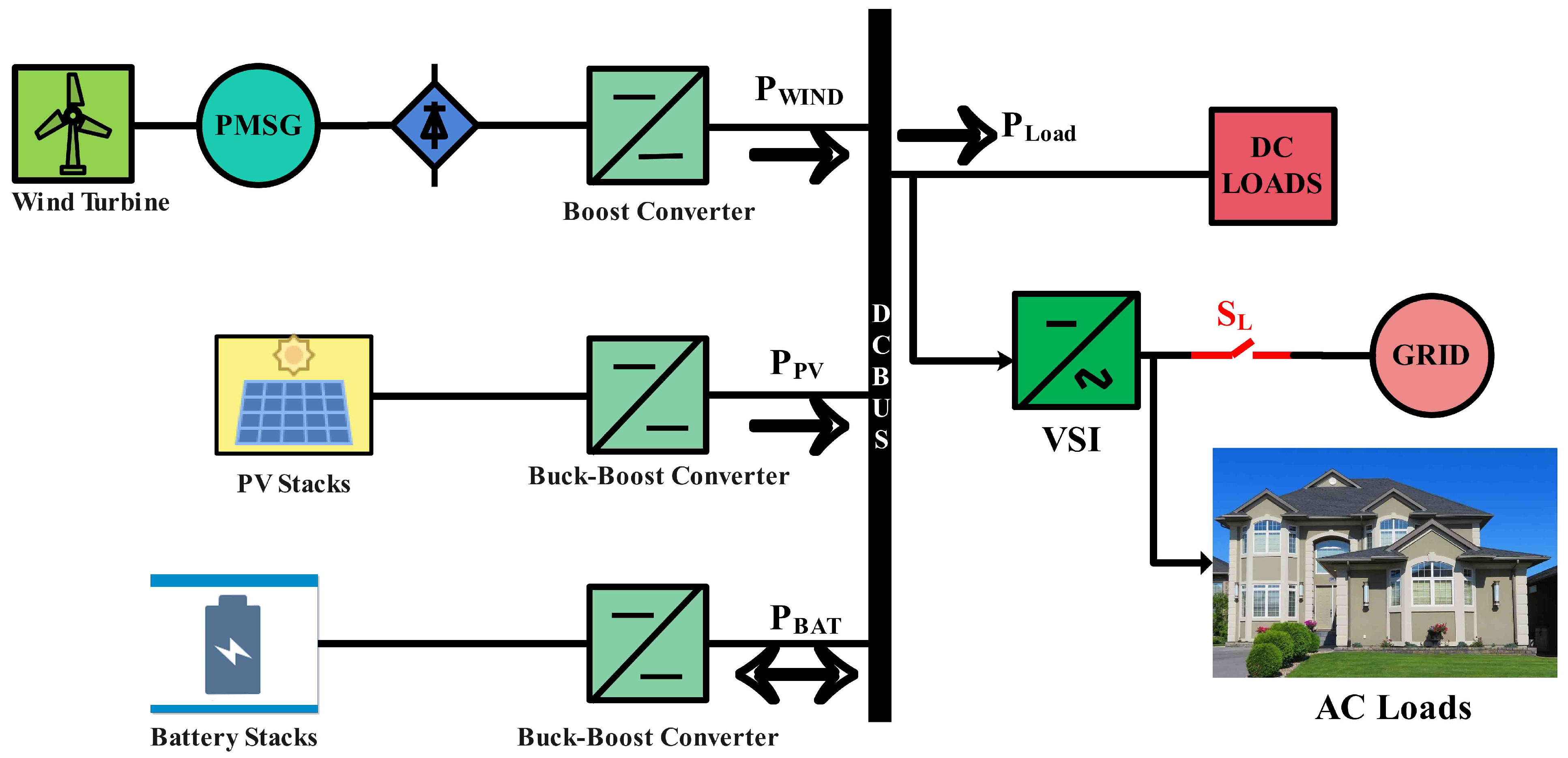
2. Modeling of the DC Sub-Microgrid

2.1. Modeling of Wind Energy Generation Unit

The proposed wind energy system (WES) model consists of a wind generation unit, including a permanent magnet synchronous generator (PMSG) connected with a wind turbine. Furthermore, the generation unit is combined with a boost converter for the current flow in one direction only, as shown in Figure 2. The wind generator operation will be controlled through a high-level controller that offers maximum power point tracking (MPPT) operation of WES. The WES converts the kinetic energy into mechanical energy. Furthermore, it is converted into electrical energy. The mechanical power generated by the PMSG can be expressed as [43].
P m = 1 2 ρ π R 2 V 3 C p ( λ , β )
where, ρ ( k g m 3 ) , R , C p and V is the air density, turbine radius, power coefficient of the turbine, and wind speed, respectively. The pitch angle of the blade ( β ) and the power coefficient of the turbine are the functions of the tip speed ratio. The practical value of C p ranges from 0.4 to 0.45, but theoretically, the maximum value can be 0.59 [43]. λ generally, can be illustrated as:
λ = ω m R V
Angular velocity of the rotor is represented by ω m r a d s . However, substituting the values of V into Equation (1), we get:
P m = 0.5 λ 3 ( ρ π R 5 ω m 5 C p )
It is observed that optimal torque control (OTC) is considered to be a practical approach to achieve MPPT due to its accuracy and simplicity [43]. Furthermore, OTC alters the torque produced in PMSG, approaching the turbine’s maximum torque reference at a specified wind speed. If the rotor is at an optimum tip speed ratio, then it has a maximum power coefficient. Therefore, λ and C p can be replaced with λ o p t and C p m a x and Equation (3) can be represented as:
P m o p t = 1 2 ρ π R 5 C p m a x λ 3 ω 3 = K p o p t ω 3
Since P m o p t = ω m T m o p t , so Equation (4) can be rewritten as:
T m o p t = 1 2 ρ π R 5 C p m a x λ 3 ω 2 = K p o p t ω 2
Equation (5) can be used to generate the reference torque, and reference current can also be determined by the following equation.
I r e f = T m o p t ω m V d
where V d represents the rectifier’s DC output voltages. The rotational speed of the generator or turbine is controlled by a DC–DC boost converter (applied as apparent load) operated in continuous conduction mode. Components of the boost converter are comprised of an inductor L w , series resistance R w , output capacitor C w , diode D 1 , and IGBT switch S 1 . The following differential equation describes the state-space model of the converter.
d i w d t = V w L w R w i w L w 1 μ 1 V d c L w
d V d c d t = 1 μ 1 i w C d c i w C d c
where average state variables μ 1 , V d c and i w shows the values of the control signal, output voltage and wind current, respectively.

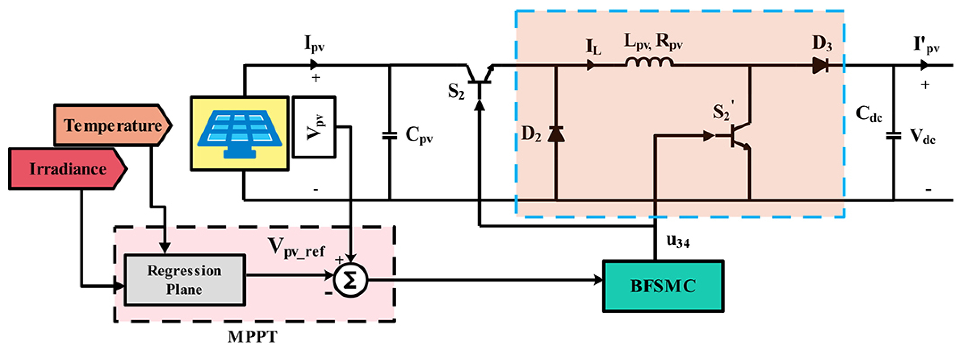
2.2. Modeling of PV System

PV system with a non-inverting buck-boost converter is used in the model. High-level control directs the operation of the PV in MPPT mode. The regression plane method is used for MPPT, which operates on temperature and irradiance data at a definite point to create a reference signal V p v r e f [44]. V p v r e f can be calculated for any value of temperature and irradiance using the following equation:
V p v r e f = 322 1.34 T e m p r a t u r e ( 0.00964 I r r a d i a n c e )
The internal circuitry of the DC–DC converter can be found in Figure 3. It comprises of an inductor L p v , IGBT switches S 2 , S 2 , two diodes D 1 , D 2 , the input capacitor C p v , and an output capacitor C d c . The converter is assumed to be in continuous conduction mode. There exist two modes of operation for the converter, when both the switches are ON and when both the switches are OFF. When S 2 and S 2 are ON, the load will be disconnected as diode D 1 is reverse biased. When S 2 and S 2 are OFF, the load is connected to L p v through diode D 2 . The buck-boost converter associated with the PV system can be expressed as the average state model by following differential equations.
d V p v d t = I p v C p v μ 2 i L C p v
d i L d t = μ 2 V p v L p v + μ 2 V d c L p v V d c L p v
d V d c d t = i L C d c I p v C d c μ 2 i L C d c
where μ 2 , V p v , i L , and V d c are the values of the control signal, PV input voltages, current of the PV system, and output voltage V d c of the PV system.

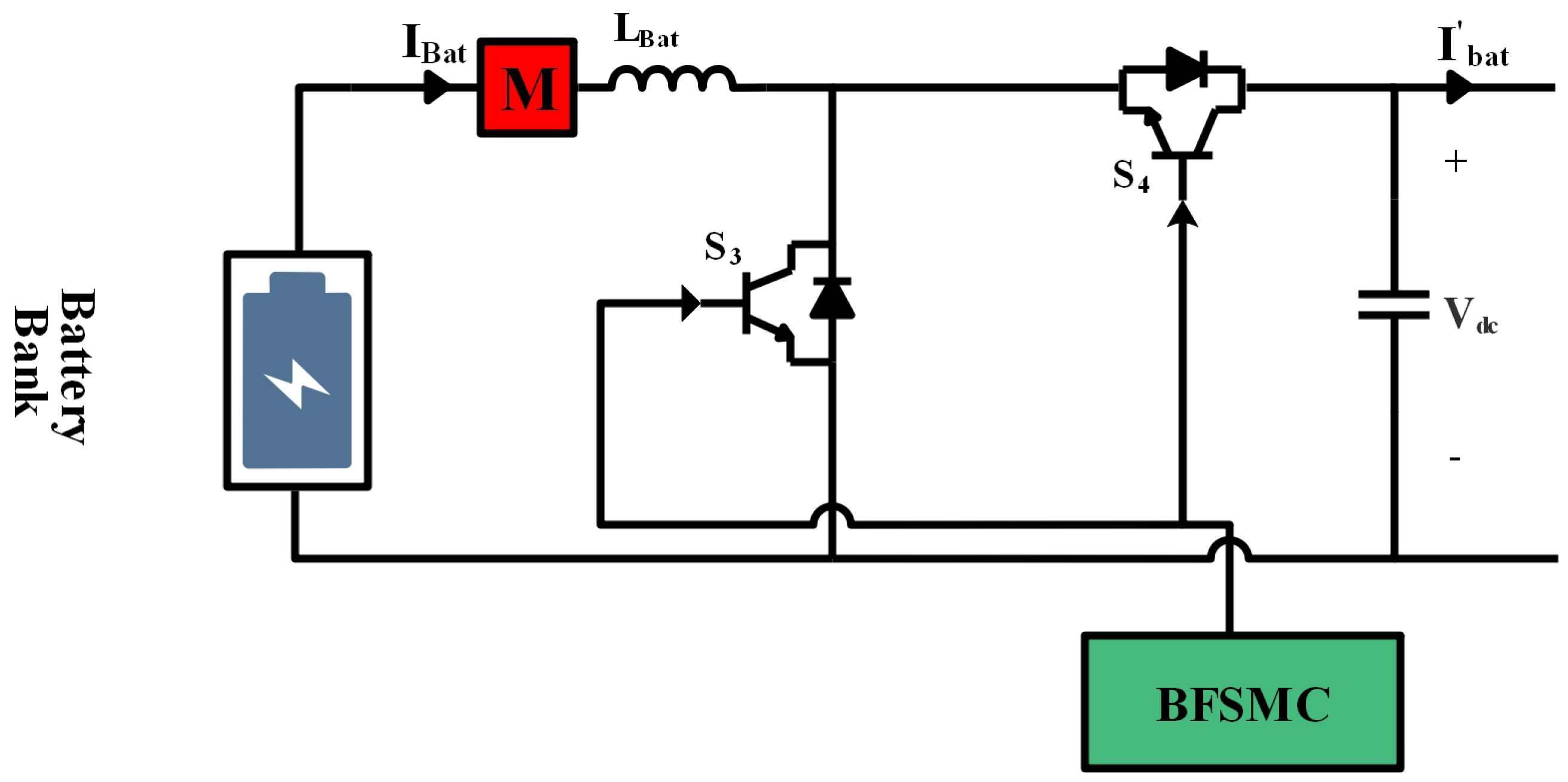
2.3. Modeling of Energy Storage System (ESS)

Figure 4 represents the circuit diagram of the battery connected with the DC-link bus via a DC–DC buck-boost converter. The circuit of the buck-boost converter is comprised of an inductor L b a t , the filter capacitor C d c , and two IGBT switches, S 3 and S 4 . Both the switches are controlled through PWM applied at their gate terminals. The buck-boost converter is connected with the battery because it can operate for charging and discharging mode depending upon the load demand and state of charge (SoC). When S 3 is ON and S 4 is OFF, the converter will be in boost mode, and discharging ( I b a t r e f > 0 ) happens to provide the required energy to the DC link bus. When S 4 is ON and S 3 is OFF, then buck ( i b a t r e f < 0 ) operation will occur, and the battery will be charging. Mathematical expression for buck-boost operation can be represented as:
K = { 1 , i f ( i b a t r e f > 0 ) 0 , i f ( i b a t r e f < 0 )
In Equation (13), i b a t r e f is the reference value of the battery current, generated according to the power demand and SoC controlled through the high-level controller. For the discharging mode of the battery, the converter can be demonstrated through the following equation:
d i b a t d t = V b a t L b a t R b a t L b a t i b a t 1 μ 3 V d c L b a t
d V d c d t = 1 μ 3 i b a t C d c i b a t C d c
where i b a t and i b a t are converter and battery current, respectively, and V d c and V b a t are DC-link bus and battery voltages. For the charging mode of the battery, the converter can be determined by the following equations:
d i b a t d t = V b a t L b a t R b a t L b a t i b a t μ 4 V d c L b a t
d V d c d t = μ 4 i b a t C d c i b a t C d c
A virtual control represents the simplification of the system by the following equation:
μ 34 = [ K 1 μ 3 + 1 K μ 4 ]
where, μ 34 is a virtual control law for battery system. By using Equation (18), buck-boost converter model for the battery can be simplified by the following two equations:
d i b a t d t = V b a t L b a t R b a t L b a t i b a t μ 34 V d c L b a t
d V d c d t = μ 34 i b a t C d c i b a t C d c

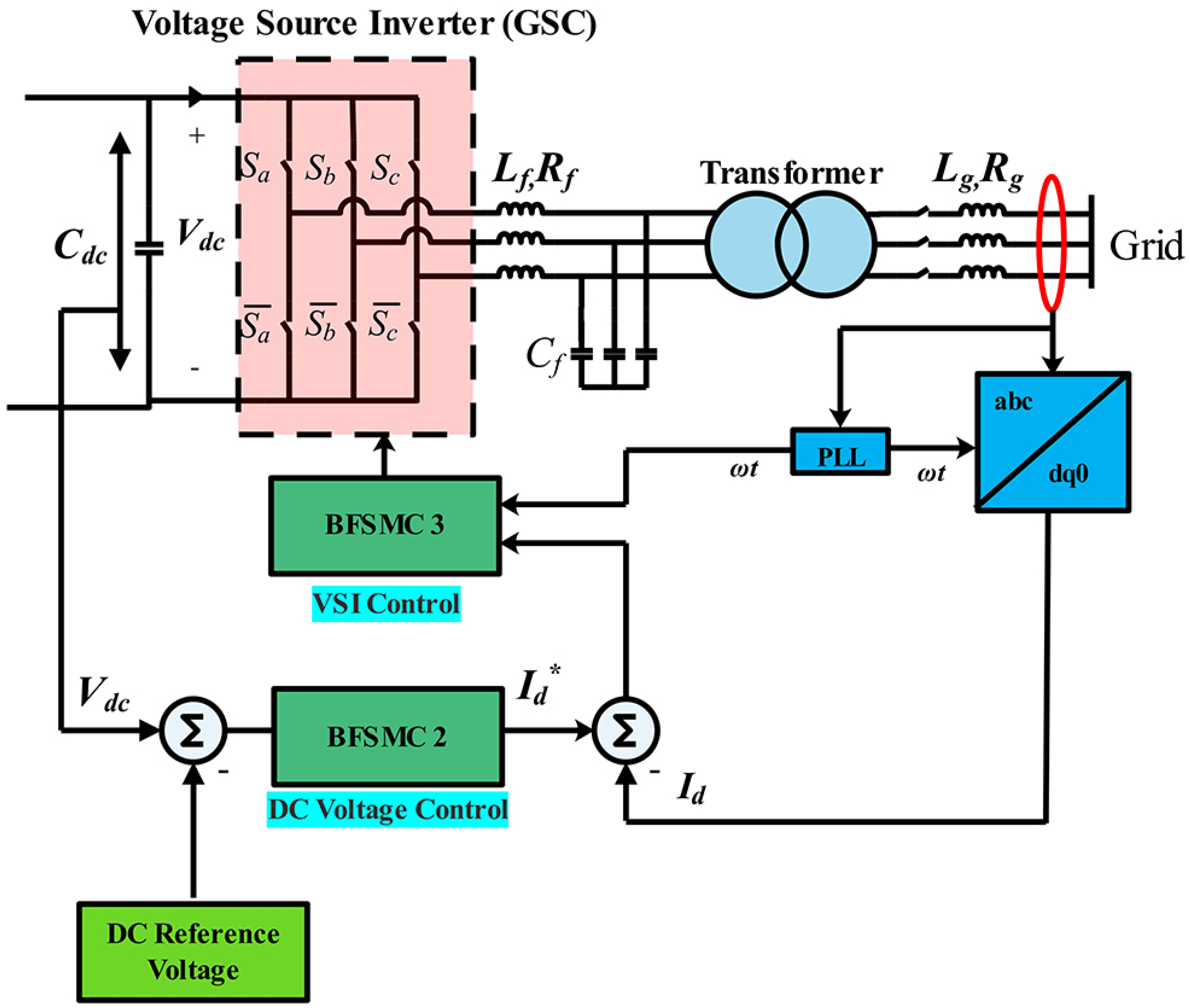
2.4. Modeling of AC Sub-Grid

AC Sub-grid configuration is shown in Figure 5. Utility grid and AC loads are supplied through the voltage source inverter (VSI). The currents and voltages of the voltage source inverter are as follows: V d , V q , I d , and I q are the output voltages and currents of the dq axis; I g d , I g q , V g d , and V g q are the utility grid dq axis currents and voltages, respectively. Operating frequency and voltages for the AC loads and utility grid are the same throughout the grid-connected operation. Parks and Clark’s dq transformation is used for VSI mathematical modeling and can be expressed by the following equations [45]:
d I d d t = V d L f R f I d L f + ω o I q + U d V d c L f
d I q d t = V q L f R f I d L f ω o I d + U q V d c L f
d V d d t = V d R C f + ω o V q + I d C f I g d C f
d V q d t = V q R C f ω o V d + I q C f I g q C f
d I g d d t = V d L g R g I g d L g + ω o I g q V g d L g
d I g q d t = V q L g R g I g q L g ω o I g d V g q L g
where variable expressions of C f , R f , and L f are the capacitance, equivalent resistance and inductance of the filter, respectively. R g and L g are the equivalent resistance of the inductor, respectively. Output voltages of VSI have angular frequency denoted by ω o .

2.5. Global Modeling (Islanded Mode)

The proposed DC sub-grid system’s global model comprises hybrid renewable sources, wind and PV systems, and battery as an energy storage unit, DC loads. The global model, as described in Section 2.1, Section 2.2 and Section 2.3 can be expressed as follows.
d x 1 d t = V i n L w R w x 1 L w x 5 1 μ 1 L w
d x 2 d t = I P V C P V μ 2 x 3 C p v
d x 3 d t = μ 2 x 2 + ( μ 2 1 ) x 5 L p v
d x 4 d t = V b a t L b a t R b a t L b a t x 4 μ 34 x 5 L b a t
d x 5 d t = 1 μ 1 x 1 C d c + 1 μ 2 x 3 C d c + μ 34 x 4 C d c I o C d c
where x 1 , x 2 , and x 4 represents the current values of inductors L w , L p v and L b a t , respectively; Voltage of capacitor C d c and C P V are expressed by x 5 and x 3 .

2.6. Global Modeling (Grid-Connected Mode)

The proposed AC sub-grid system’s global model comprises hybrid renewable sources, wind and PV systems, main grid, and AC loads. The global model, as described in Section 2.1, Section 2.2, and Section 2.4 can be expressed as follows:
d x 1 d t = V i n L w R w x 1 L w x 5 1 μ 1 L w
d x 2 d t = I P V C P V μ 2 x 3 C p v
d x 3 d t = μ 2 x 2 + ( μ 2 1 ) x 5 L P V
d x 5 d t = 1 μ 1 x 1 C d c + 1 μ 2 x 3 C d c I o C d c 3 2 C d c x 5 ( x 7 x 9 + x 6 x 8 )
d x 6 d t = x 8 L f R f x 6 L f + w o x 7 + U d x 5 L f
d x 7 d t = x 9 L f R f x 7 L f w o x 6 + U q x 5 L f
d x 8 d t = x 8 R C f + w o x 9 + x 6 C f x 10 C f
d x 9 d t = x 9 R C f w o x 8 + x 7 C f x 11 C f
d x 10 d t = x 8 L g R g x 10 L g + w o x 11 V g d L g
d x 11 d t = x 9 L g R g x 11 L g w o x 10 V g q L g
where, x 6 , x 7 , x 8 , and x 9 are the currents and voltages values of dq axis; x 10 and x 11 shows the values of utility grid dq axis currents, respectively; w o is the angular frequency during the grid-connected mode of microgrid. In the next section, the controller’s design is discussed to control the AC and DC bus voltages during the islanded mode and grid-connected mode.

3. Controller Design

3.1. Barrier Function for Sliding Mode Controller

Let us suppose that first order system dynamics are given as:
x ( t ) ˙ = u ( t ) + d ( t )
where system’s disturbance is d ( t ) with known value, i.e., d ( t ) d m , where d m is a finite positive integer. Control input of the system’s state can be denoted as u ( t ) R . By assuming that the bounds of disturbances acting on the system are unknown. A first-order sliding mode controller is required to stabilize the system, and is given as:
u ( t ) = K ( t ) s i g n ( x )
However, there are two major concerns regarding the first-order sliding mode controller, firstly chattering and secondly gain selection of optimum control. Thus, higher-order SMC is considered an efficient approach to resolve the chattering, and adaptive SMC to mitigate the gain section of optimum control. Additionally, barrier function-based adaptive SMC can be used to tackle both the issues mentioned above. It is evident from Equation (43) that control law is a function of the system’s state, and it varies with time. There are two different approaches assumed to define the barrier functions in this paper [46].
  • Positive definite barrier functions (PBFs): Let assume some fixed ε > 0 , which leads to a continuous even function K b : x ] ε , ε [ K b ( x ) [ b , [ , firmly cumulative on [ 0 , ε [ . So PBF will be:
    K P B x = ε F ¯ ε | x | i.e. , K P B 0 = F ¯ > 0
  • Positive semi-definite barrier functions (PSBFs): Following equation defines the PSBF as:
    K P S B x = | x | ε | x | i.e. , K P S B 0 = 0
The defined function in Equations (44) and (45) provides adaptive gains based on PBF and PSBF. Therefore, when ε 0 then K 0 . If state lies in the vicinity of origin, i.e., x ε < 1 , then K x ε , that certifies the convergence of state x to zero. Moreover, proof refers to the claim can be identified in [46].

3.2. Control of Islanding Mode of DC Sub-Grid

In Section 2.5, the global model during the islanding mode of DC sub-grid is presented. It is clear that VSI side will not be utilized during this mode, and hybrid renewable energy sources and battery provides the necessary power to the loads. Islanded mode of the microgrid is activated when the switch S L is OFF as shown in the Figure 6. The following equation can express the tracking errors to make sure the stable operation of the DC sub-grid as:
{ e 1 e 2 e 3 e 4 } = x 1 I w r e f x 2 V p v r e f x 4 I b a t r e f x 5 V d c r e f
where I w r e f , V p v r e f , I b a t r e f , and V d c r e f are the reference values of wind current, PV current, battery current, and the reference voltage of common DC bus, respectively. Assuming the time derivative in Equation (46) will give the following expressions:
e 1 ˙ = V i n L w R w x 1 L w x 5 1 μ 1 L w I w r e f + ϑ 1 ˙
e 2 ˙ = I P V C P V μ 2 x 3 C p v V p v r e f + ϑ 2 ˙
e 3 ˙ = V b a t L b a t R b a t L b a t x 3 μ 34 x 5 L b a t I b a t r e f ˙ + ϑ 3
e 4 ˙ = 1 μ 1 x 1 C d c + ( 1 μ 2 ) x 3 C d c + ( μ 34 ) x 4 C d c I o C d c V d c r e f ˙ + ϑ 4
where ϑ 1 , ϑ 2 , ϑ 3 and ϑ 4 are the untilled bounds and uncertain dynamics and the deftness of the controller tends to remove these parameters adaptively. From Equations (47)–(49), the control laws can be derived as:
μ 1 = 1 + L w x 5 V i n L w R w x 1 L w I w r e f ˙ + l w x 5 ( e 1 ˙ )
u 2 = C p v x 3 ( e 3 ˙ + I p v C p v V P V r e f ˙ )
u 34 = L b a t x 5 ( V b a t L b a t R b a t L b a t x 4 I b a t r e f ˙ e 3 ˙ )
For the error convergence towards zero, barrier functions for e 1 ˙ , e 2 ˙ , e 3 ˙ and e 4 ˙ are illustrated below considering the Equation (43) as:
e 1 ˙ = K 1 e 1 s g n ( e 1 )
e 2 ˙ = K 2 e 2 s g n ( e 2 )
e 3 ˙ = K 3 e 3 s g n ( e 3 )
e 4 ˙ = K 4 e 4 s g n ( e 4 )
where K 1 , K 2 , K 3 and K 4 are the adaptive gains, whose values can be determined by using the Equations (44) and (45) as:
K i ( t ) = { K P B ( t ) , K P B ( t ) ˙ = F ¯ | e i ( t ) | , i f ( 0 < t < t ¯ ) K P S B | e i ( t ) | , i f ( t > t ¯ )
where i = 1, 2, 3, 4, and F ¯ to be a positive arbitrary number. Hence, Equations (51)–(53) can be rewritten to express the controllers for DC sub-grid as:
μ 1 = 1 + L w x 5 V i n L w R w x 1 L w I w r e f ˙ + l w x 5 K 1 e 1 s g n e 1
μ 2 = C p v x 3 K 2 e 2 s g n ( e 2 ) + I p v C P v V P V r e f ˙
u 34 = L b a t x 5 ( V b a t L b a t R b a t L b a t x 4 I b a t r e f ˙ + K 3 e 3 s g n ( e 3 ) )

3.3. Control during Grid-Connected Mode of AC Sub-Grid

In Section 2.4, the global model during the grid-connected mode of AC sub-grid is presented. VSI side is utilized during this mode and hybrid renewable energy sources contribute with the main grid to provide the necessary power to the utility grid. The battery will be kept in idle mode due to the availability of the grid. The following equation can express the tracking errors to make sure the stable operation of the AC sub-grid as:
e 4 e 5 e 6 = x 5 V d c r e f x 6 I d r e f x 7 I q r e f
where I d r e f and I q r e f are the reference values of VSI dq axis currents. Errors for wind and PV systems are already defined. The grid-connected mode of the microgrid is activated when switch S L is ON as shown in Figure 6. Assuming the time derivative in Equation (62) will give the following expressions:
e 4 ˙ = 1 μ 1 x 1 C d c + 1 μ 2 x 3 C d c I o C d c V d c r e f ˙ + ϑ 4 3 2 C d c x 4 x 9 x 7 + x 6 x 8
e 5 ˙ = x 8 L f R f x 6 L f + ω o x 7 + U d x 5 L f I d r e f ˙ + ϑ 5
e 6 ˙ = x 9 L f R f x 7 L f ω 0 x 6 + U q x 5 L f I q r e f ˙ + ϑ 6
where ϑ 4 , ϑ 5 and ϑ 6 are the unknown bounds and uncertain dynamics and the accuracy of the controller tends to remove these parameters adaptively. From Equations (64) and (65), the control laws can be derived as:
U d = L f x 5 ( e 5 ˙ + x 8 L f + R f x 6 L f ω o x 7 + I d r e f ˙ )
U q = L f x 5 ( e 6 ˙ + x 9 L f + R f x 7 L f + ω o x 6 + I q r e f ˙ )
For the error convergence towards zero, barrier functions for e 5 ˙ and e 6 ˙ are illustrated below considering the Equation (43) as:
e 5 ˙ = K 5 e 5 s g n ( e 5 )
e 6 ˙ = K 6 e 6 s g n ( e 6 )
where K 5 and K 6 are the adaptive gains, whose values can be determined by using. Equations (44) and (45) as:
K β ( t ) = { K P B ( t ) , K P B ( t ) ˙ = F ¯ | e β ( t ) | , i f ( 0 < t < t ¯ ) K P S B | e β ( t ) | , i f ( t > t ¯ )
where β = 5, 6, and F ¯ is a positive arbitrary number. Control laws for WES and PV system will remain the same as given in Equations (59) and (60). Hence, control laws for AC-grid side can be expressed by the following equations as:
U d = L f x 5 ( K 5 e 5 s g n ( e 5 ) + x 8 L f + R f x 6 L f ω o x 7 + I d r e f ˙ )
U q = L f x 5 ( K 6 e 6 s g n ( e 6 ) + x 9 L f + R f x 7 L f + ω o x 6 + I q r e f ˙ )
The active power reference generation during the grid-connected mode can be determined by solving the Equation (63).
I d 🟉 = x 6 🟉 = 2 C d c x 5 3 x 8 1 μ 1 x 1 C d c + 1 μ 2 x 3 C d c I o C d c x 5 ˙ + K 4 e 4 s g n ( e 4 )
where c 2 is a constant having a positive value to ensure the convergence of the error e 4 towards zero. Equation (63) ensures the stability of DC and AC bus voltages by regulating the flow of active power between AC and DC sides of the microgrid.

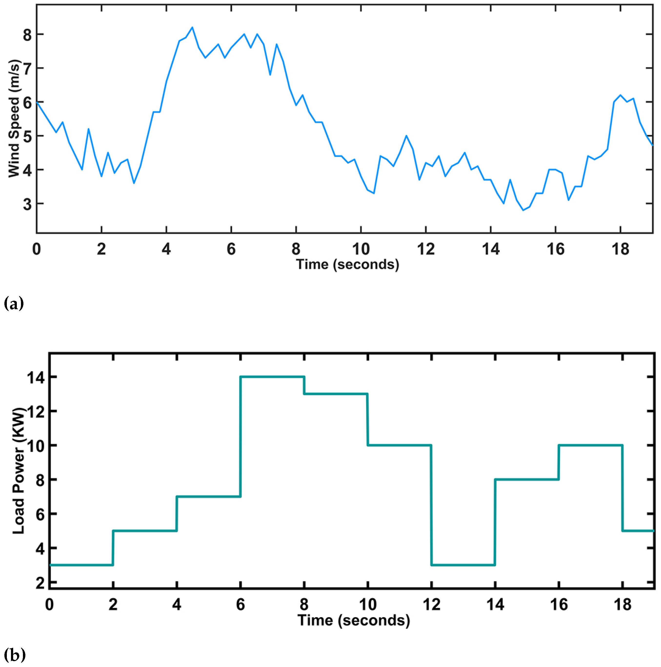
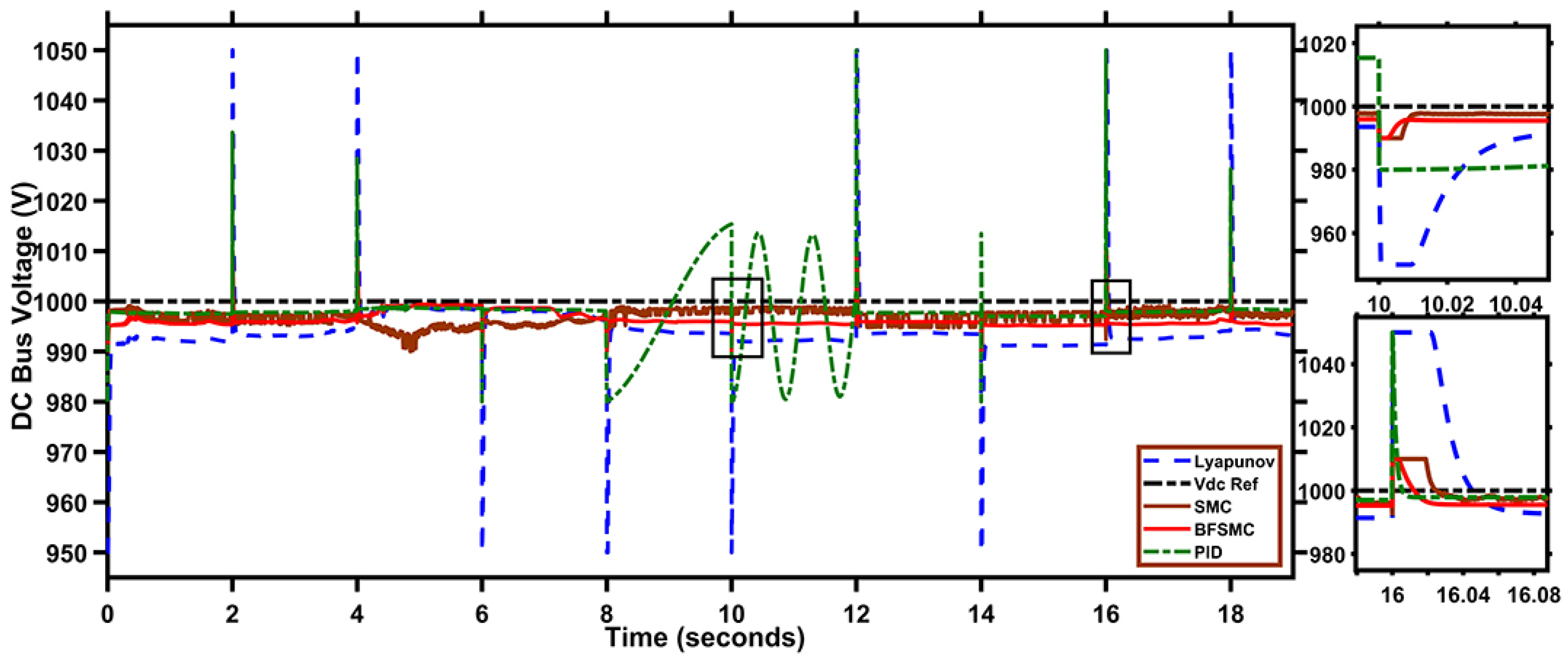
4. Results and Discussion
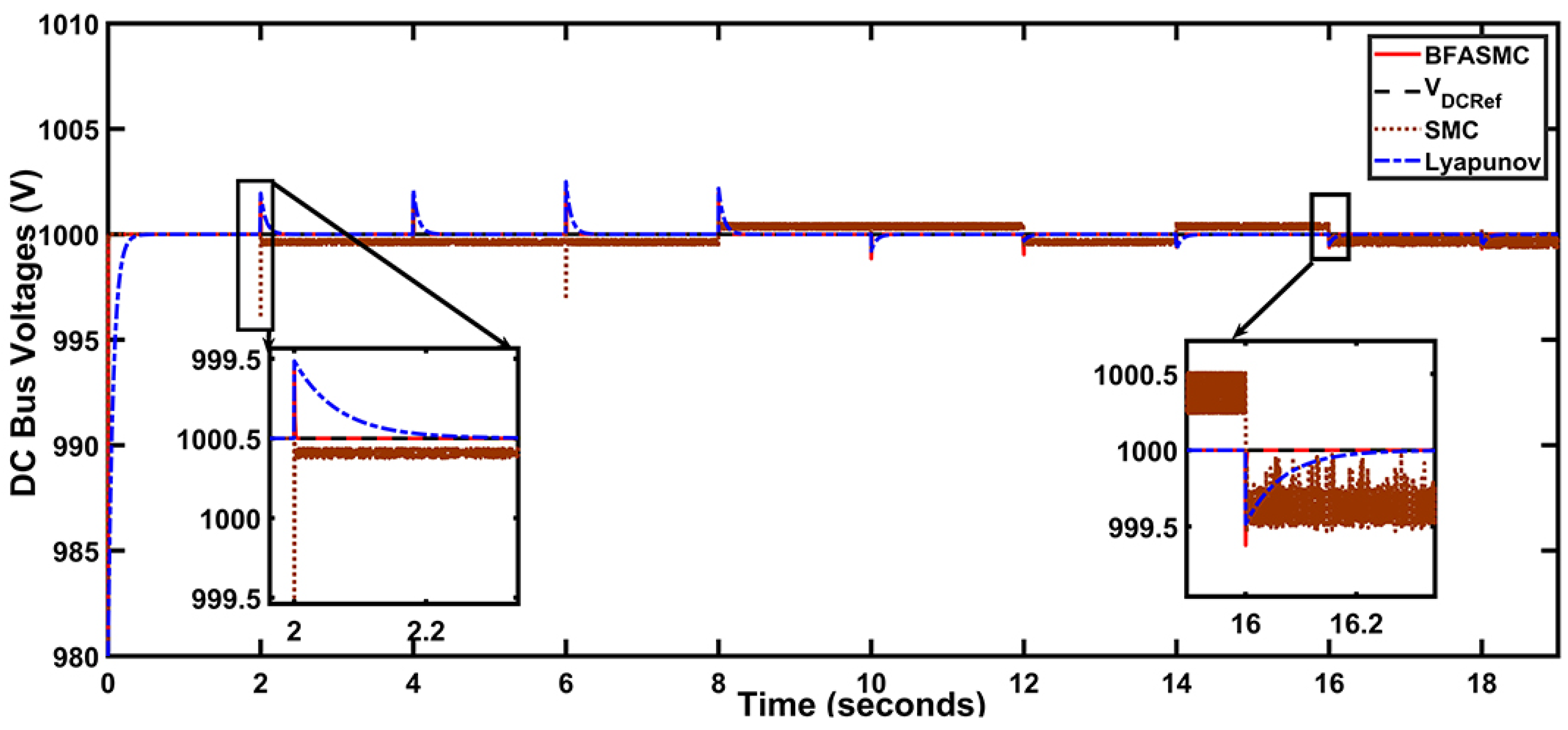
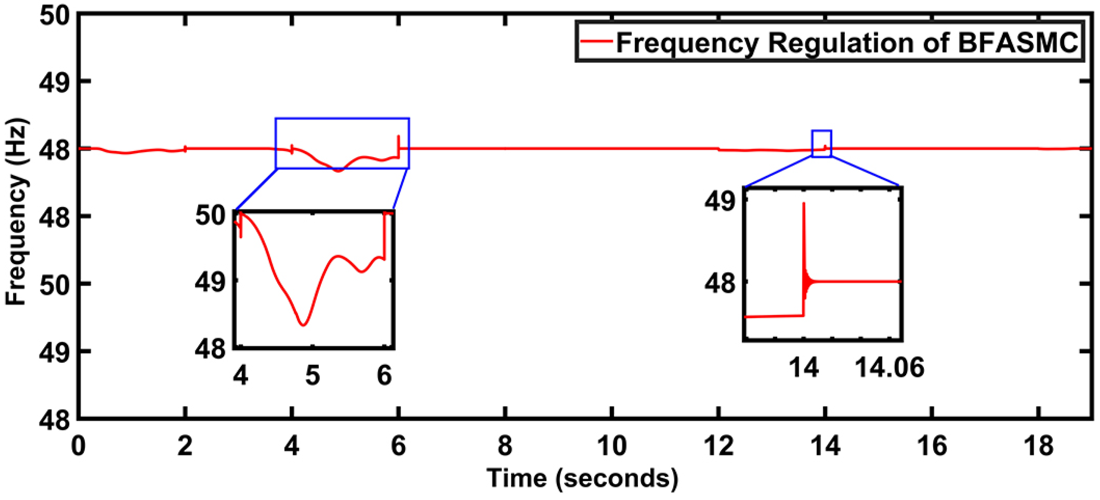
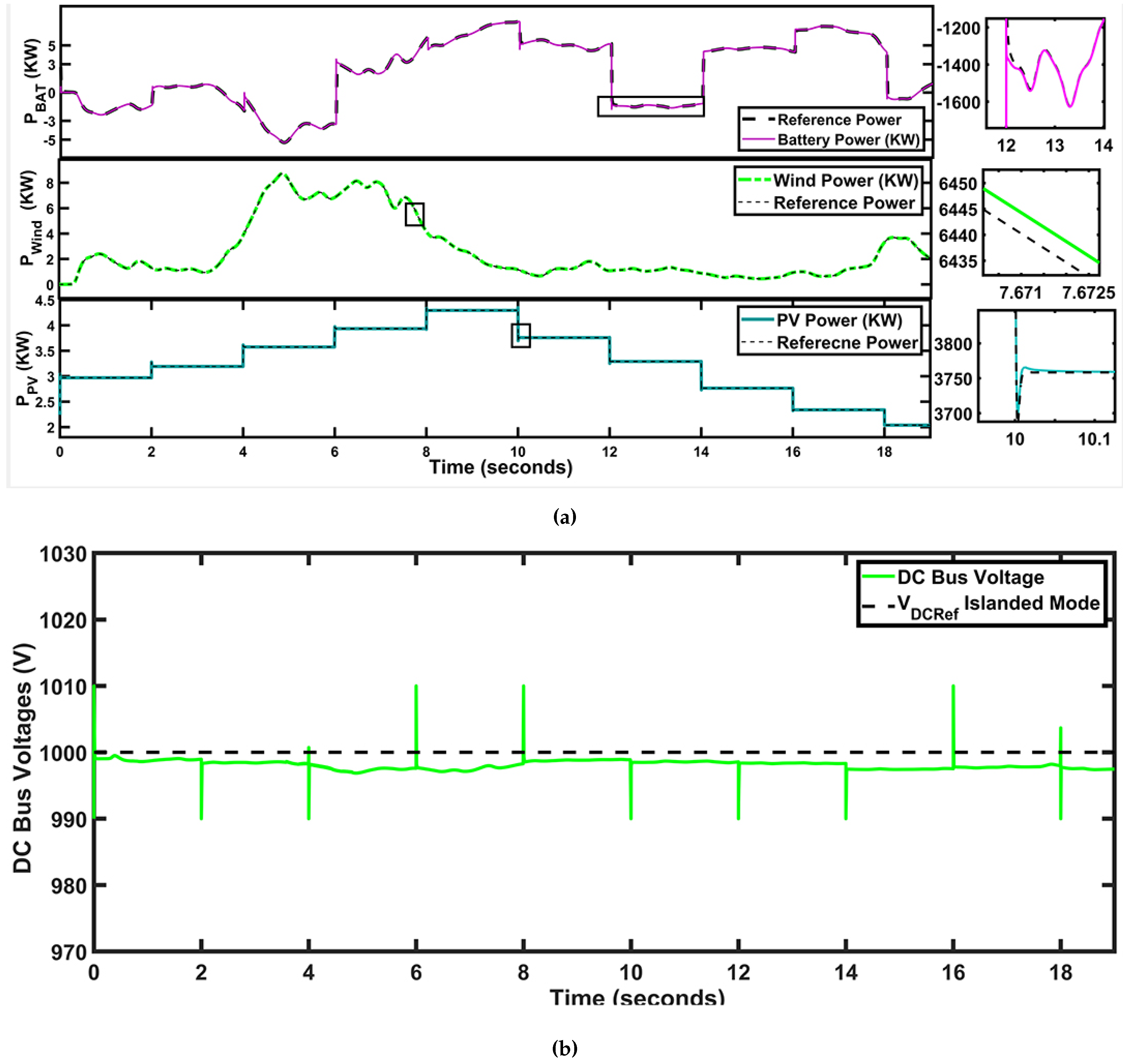
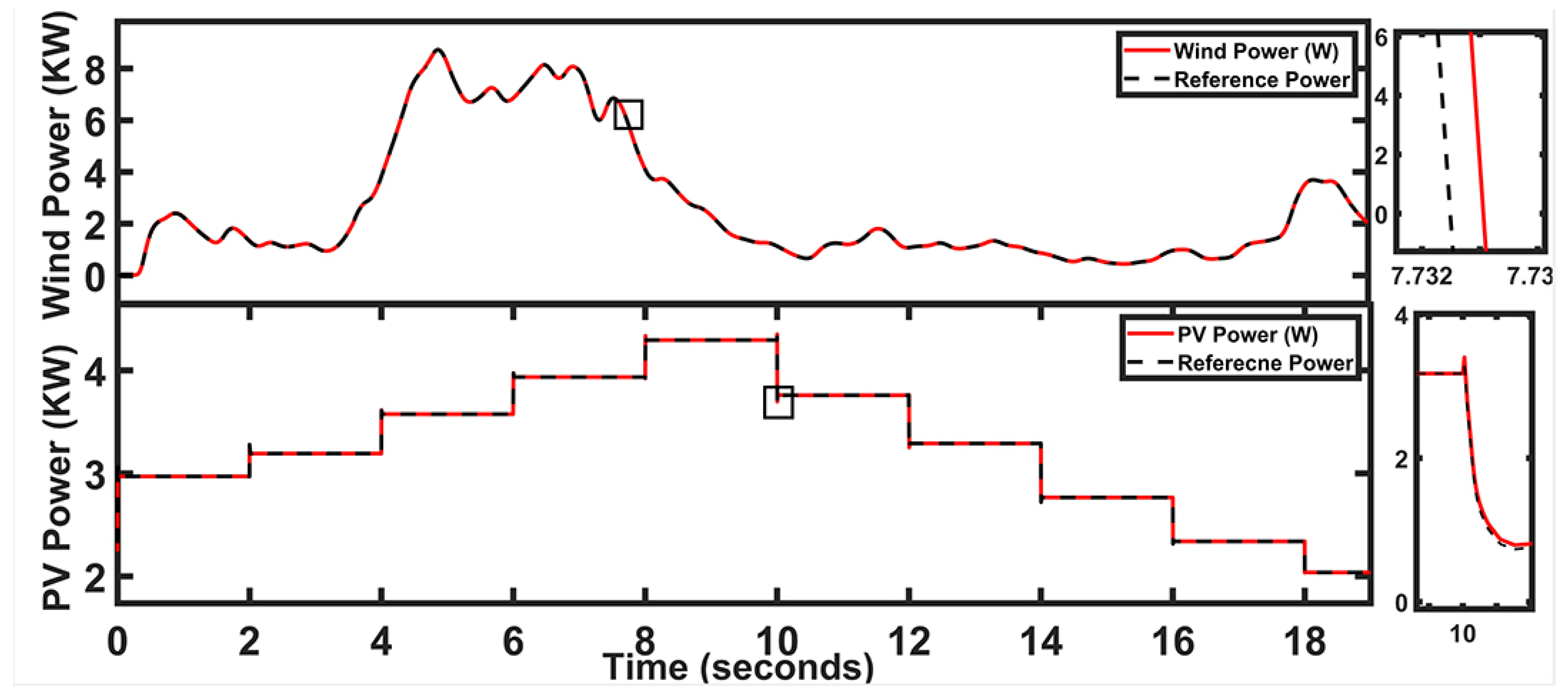
To check the proposed system’s performance, MATLAB/Simulink tool is used to simulate the AC/DC hybrid microgrid system. Moreover, two modes of operation were studied (Islanded and grid-connected mode), under which the centralized barrier function-based adaptive sliding mode controller’s performance is analyzed. In both the AC/DC microgrid modes, the primary aim is to stabilize the AC/DC bus voltages. The general configuration of the non-linear adaptive control technique illustrating the design procedure and structure during the entire operation of the micro-grid is given in Figure 7. Where energy sources (wind, PV, and battery) are attached with the power converters. RESs are firstly attached with the MPPT blocks before connecting with the power converters. Powers of the RESs are fed to the energy management block to ensure the power balance in the microgrid by the appropriate use of ESS during the islanding mode. Moreover, during the grid-connected mode, ESS will be in idle mode and the VSI side will be used to ensure the flow of power between the grid and RESs as per the load demands. The centralized barrier function adaptive SMC block generates all the control laws during grid-connected and islanding mode. Table 1 shows the irradiance and temperature change due to the weather conditions, heat, fog, and dust on the panels and generated MPPT voltages for the PV stacks in the system. The designed parameters used in the microgrid are listed in Table 2, Table 3 and Table 4. Moreover, Table 5 shows the comparison results of the proposed controller as compared to the other non-linear techniques. Simulations are performed for 19 s only. The profile of the wind speed for the considered model is shown in Figure 8a and the DC load power profile is given in Figure 8b. The references are generated by the high-level controller, assuming that they will ensure energy balance during the operation of the microgrid. However, these references are not designed separately.

4.1. Islanding Mode

Under the Islanding mode of microgrid, the steady-state and dynamic response of MG is analyzed. The output power of wind turbine, PV system, battery, and stable voltages at the DC bus is illustrated in Figure 9a,b under their allocated reference values, respectively. The hybrid microgrid converts into an isolated system during the islanding mode and there are two possible scenarios to be kept in mind to ensure the power balance. Firstly, under low irradiance and wind speed with heavily attached load with the system, ESS will contribute a good portion of the power to ensure the DC bus regulation. Secondly, with high irradiance and wind speed with low power load attached with the system, both PV and wind generate sufficient power to ensure the power balance at the DC bus and excess power charges the ESS.
The battery tracks reference generated at the high-level controller side to ensure the power balance and keep the stable voltage at the DC bus in islanding mode. Moreover, wind power and PV power also track their respective reference MPPT values during islanding mode, ensuring the regulated DC bus voltages. The zoomed-in views are attached, confirming the steady-state error under transient conditions. At t = 0–0.5 s, generation at WES is zero, power generated by the PV system is 3 kW and load demand is 3 kW. PV provides the required power to the load. At t = 0.5–1 s, generation at WES increases from 0 to 2 kW, however, PV generation is the 3 kW, and load power is 3 kW. Hence, both the PV and WES contribute to providing the necessary power to the load and the remaining power is utilized to charge the battery, as shown in Figure 10. During t = 6–11 s, WES generation changes from 5 kW to 1.5 kW, and PV generation changes from 4.3 kW to 3.8 kW. Load power required during this period ranges from 14 kW to 10 kW. Hence, the battery discharges to ensure the DC bus regulation by providing the additional power. Hence, it must be noticed that RESs and ESS both provide the required power during the islanded mode making sure that not all the dependency is made on one resource only; moreover, RESs charge the battery under low load power during the islanded mode.
One of the main objectives achieved in this research work can be seen in Figure 9b, which depicts the regulation of DC bus under varying load conditions and shows the effectiveness of the applied controller. It can be seen that the DC bus successfully tracks the reference voltage. A comparison of the proposed BFASMC has been ensured in Figure 10, which shows the efficiency, improved steady-state (SS) error, and lesser settling time as compared to the proportional integral derivative (PID) controller, sliding mode controller, and Lyapunov controller. The proposed BFASMC achieves SS in just t = 0.003 s with 0.1% overshoot and 0.03s settling time, however, SMC takes t = 0.051 s with 0.6 s settling time and 4.7% overshoot with continuous chattering, PID takes t = 0.5 s with 15% overshoot and 0.6 s settling time, and Lyapunov takes t = 0.02 s with 2.1% overshoot and 0.2% steady-state error, which can be observed in zoomed-in windows. Spikes in DC bus voltage regulations are due to the variation in the load, PID and Lyapunov controllers take more SS response time, low transient response, and more settling time. Moreover, SMC exhibits a huge amount of chattering throughout the operation of the microgrid, which is not suitable from the DC bus regulation point of view. However, BFASMC performs better during the islanded mode of microgrid as compared to other controllers.

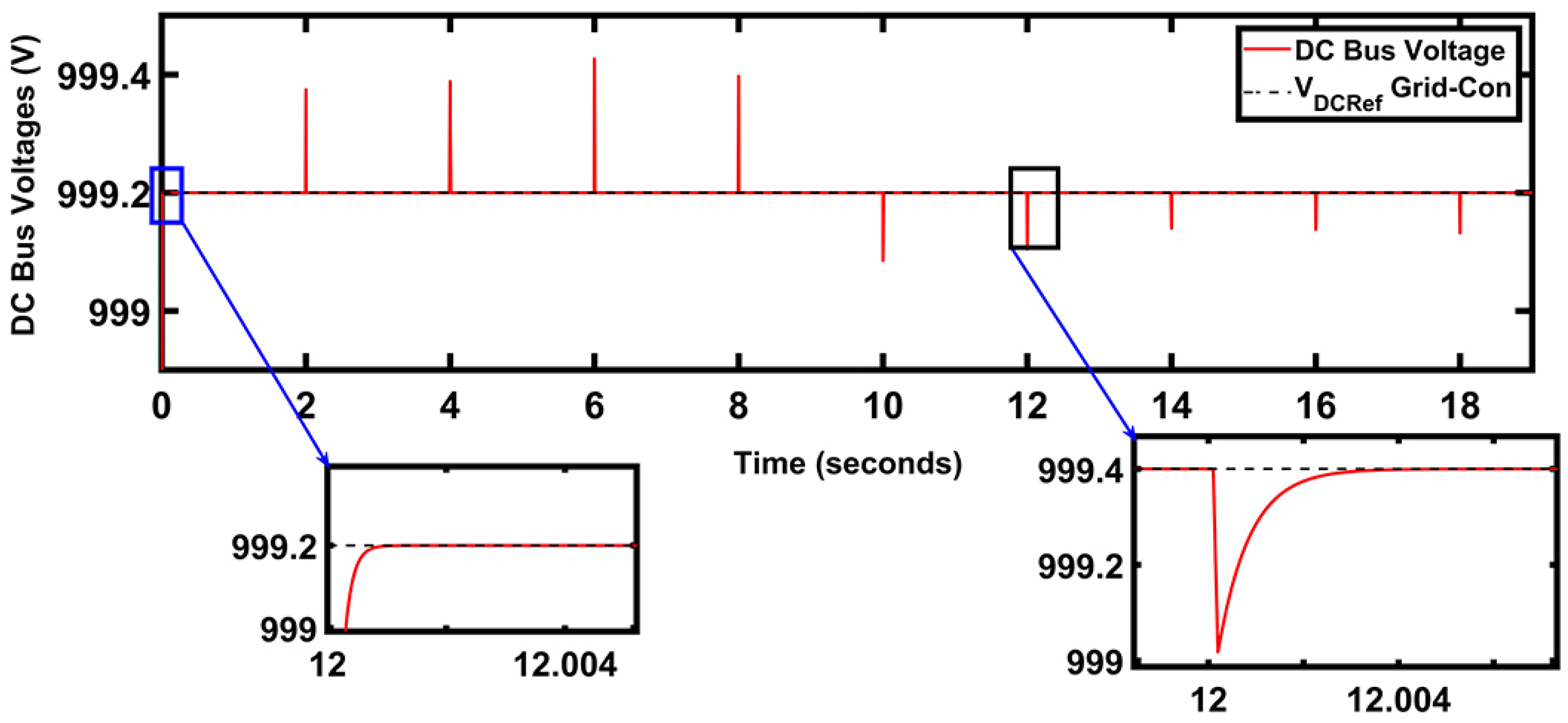
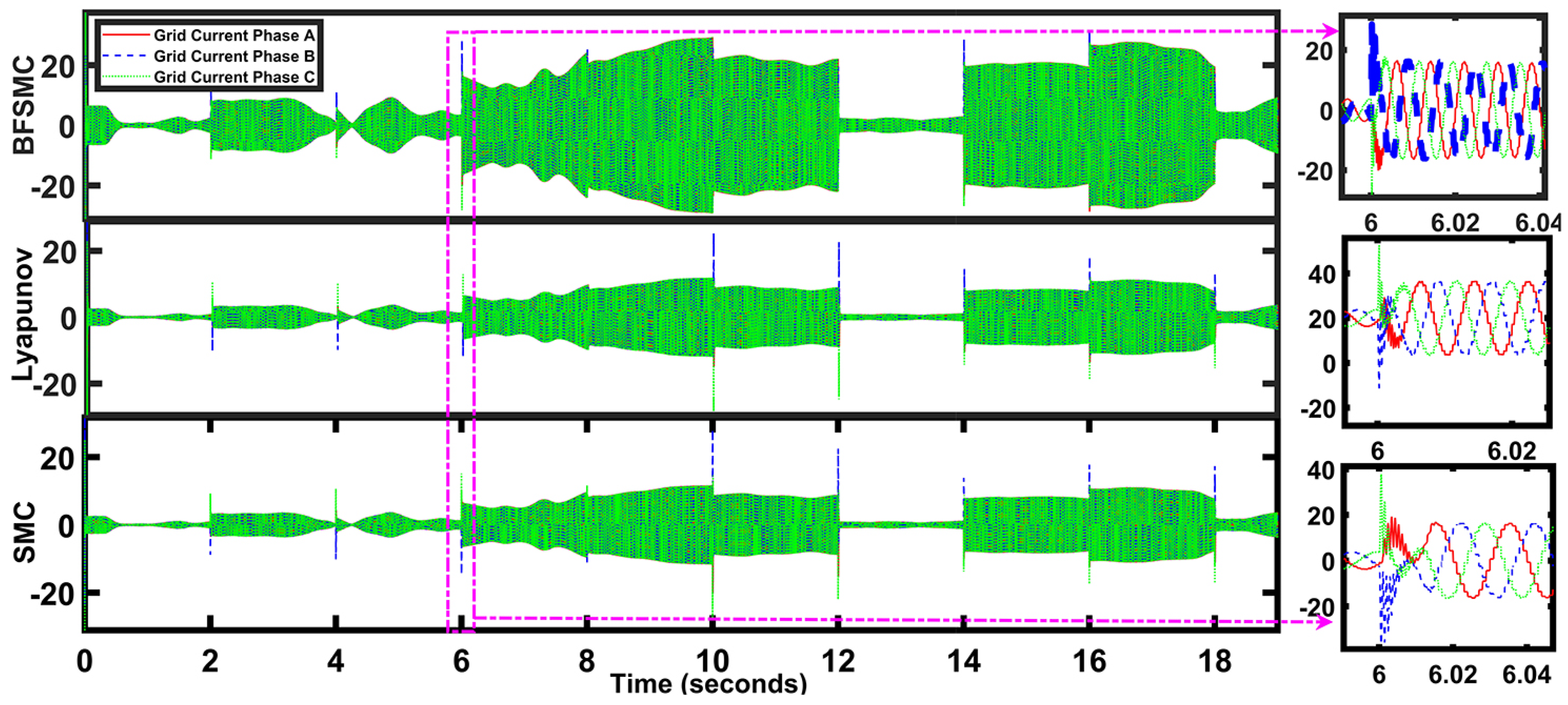
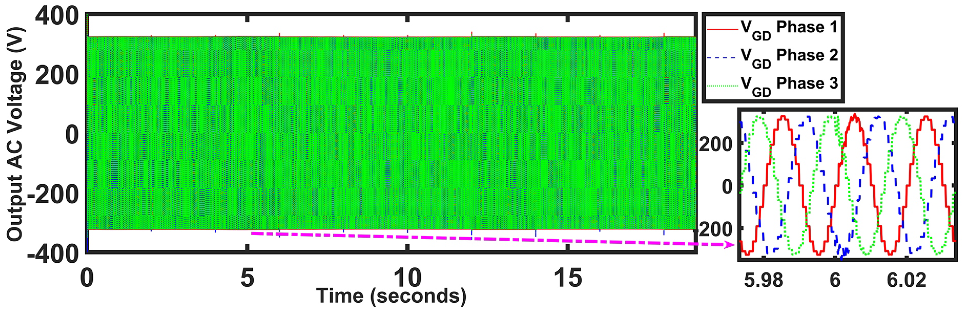
4.2. Grid-Connected Mode

In grid-connected mode, performance is checked on the basis of a specified framework to ensure DC and AC bus voltage regulation. Reference generated in the Equation (73) shows the flow of the active power between the DC and AC sides as per the load requirements throughout the grid-connected mode. If the generated power by PV and wind is less than the demand then, power flows towards the DC side from the utility grid and, if the generated power is greater than the demand, then excessive power is delivered to the utility grid. Figure 11 shows the power injected by the WES and PV system to the microgrid. The operation of the hybrid RESs is in maximum power point tracking mode during the entire grid operation. Due to the availability of the grid power in the system, ESS is kept in the idle mode under the grid-connected operation. The generation of the wind and PV is depending on the weather conditions. Figure 8a shows the wind speed profile. It can be observed that wind speed varies due to weather conditions. The rotor speed of the wind turbine is controlled by the optimal torque control (OTC) method to extract the MPPT from the WES. Figure 11 shows the MPPT power generation of the RESs during the grid-connected mode.
During the grid-connected mode, AC voltage at the voltage source inverter (VSI) side will be automatically balanced due to the connection with the main grid. The objective will be to stabilize the DC bus voltage. PV and WES are operated in MPPT and the load profile is given in Figure 9. At t = 6–8 s, the load current changes from 7 kW to 14 kW, and hybrid RESs cannot provide all the power due to generation constraint, therefore, active power will flow from the AC side to the DC side to ensure the power balance at DC bus. During t = 12–14 s, load power is 3 kW, and it can be noticed that WES and PV are generating more power than the required load power; therefore, power from the DC side to the AC side will flow to ensure the stable voltage at the DC bus.
The voltage regulation at the DC link bus during the grid-connected mode can be seen in Figure 12. Comparison of proposed BFASMC during the grid-connected mode is done with PID, Lyapunov, and sliding mode controller techniques. It can be clearly identified from Figure 13 that BFASMC, as compared to other controller techniques, tracks the reference 1000 V accurately with 0.001 s settling time, 0.1% overshoot, and zero steady-state response. Spikes can be seen at the load changing periods, but they are under acceptable range and during BFASMC the recovery time is very minimal, which validates the effectiveness of the proposed technique. The sliding mode controller tracks the reference voltages with 0.003 s settling time, 0.05% steady-state error, and high chattering throughout the considered period, which is not acceptable for the smooth and uninterruptable operation of the microgrid. The Lyapunov controller has minimum chattering but it has high 0.2 s settling time and 0.29% overshoot during the varying load conditions.
The stabilized frequency during the grid-connected mode can be seen in Figure 14. Grid current and voltages during the grid-connected mode are shown in Figure 15 and Figure 16, respectively. In addition, the comparison of the designed VSI controllers is performed to validate the performance of BFASMC for VSI side. Lyapunov and SMC controller are compared with the proposed BFASMC and simulation results can be seen in Figure 17 and Figure 18. Table 5 shows the difference between the PID, SMC. Lyapunov and BFASMC in terms of settling time, rise time, percent overshoot, and steady-state error percentage.

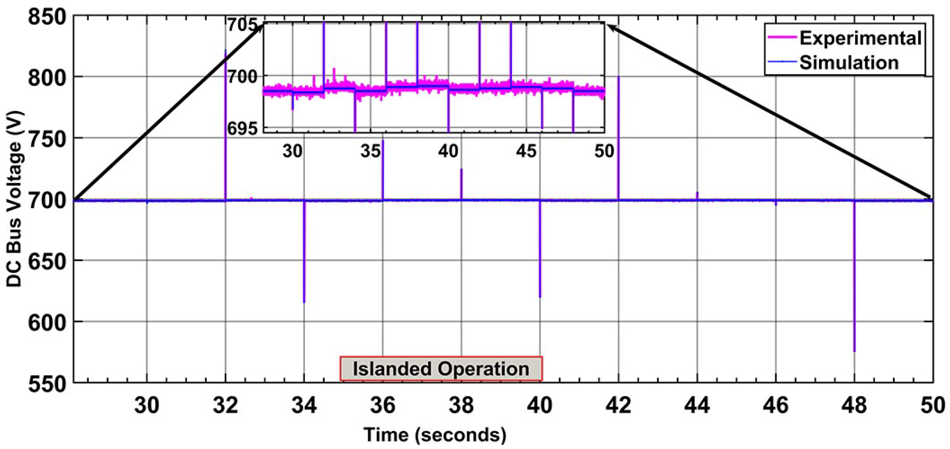
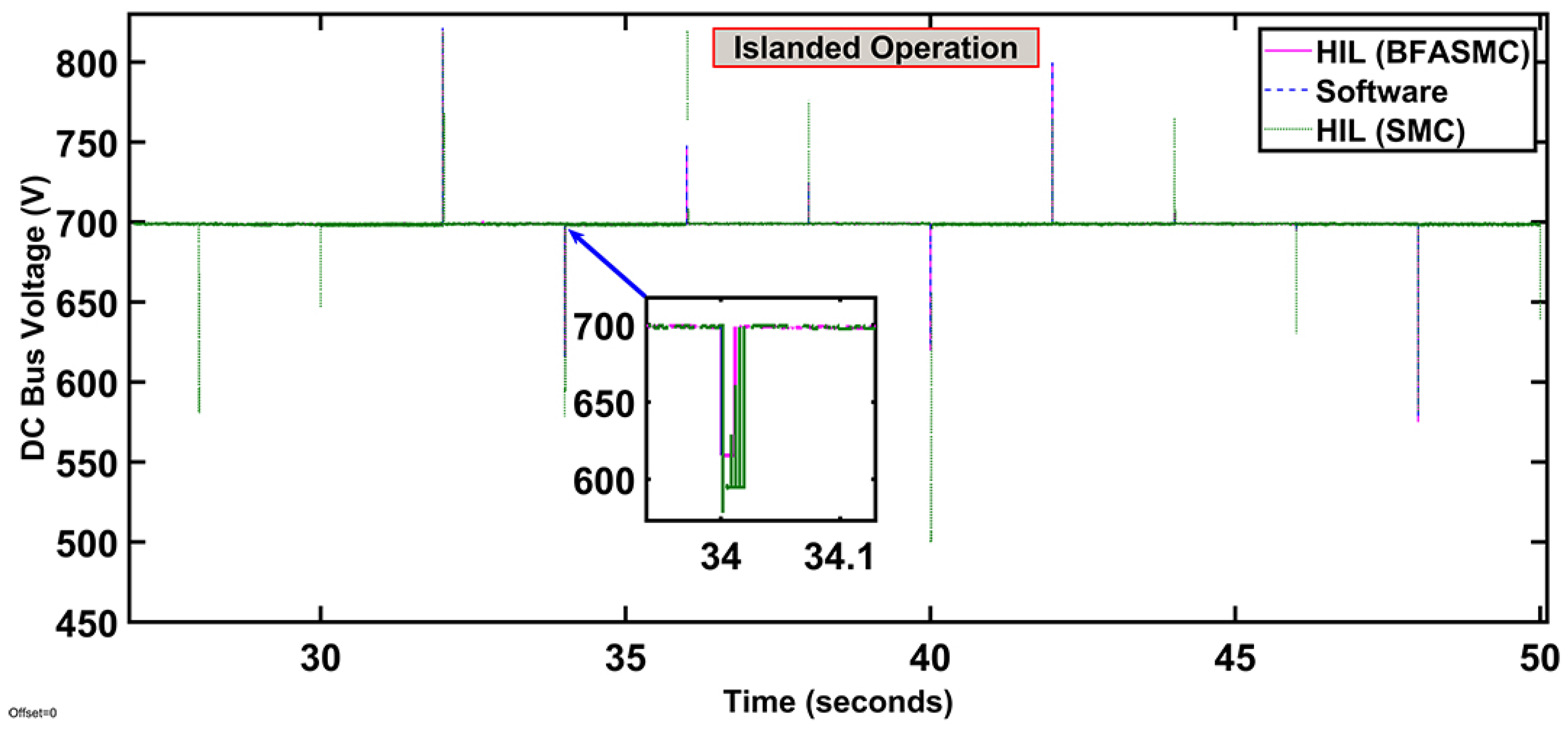
4.3. Hardware in the Loop Analysis

To enhance the validity of the proposed controller, hardware in the loop (C-HIL) analysis evaluates the real-time performance of the BFASMC controller before its practical implementation and HIL setup is shown in Figure 19. To generate the control signals, this hardware in loop analysis uses C2000 Delfino MCU F28379D LaunchPad with dual-core central processing units (CPUs) with an operating frequency of 200 MHZ, and the interface is provided with MATLAB/Simulink using Delfino T1C2000 support through embedded coder. The average small-signal model of hybrid renewable energy sources (PV and WES), including energy storage system (battery), power converters, and grid, is modeled on MATLAB and machine coding is done on MCU F28379D Launchpad-1. Moreover, control laws of BFASMC are implemented on Launchpad-2 with a 10 kHz switching frequency. The general-purpose input/output (GPIO) ports at Launchpad-1 based on the machined model have connected with the pulse width modulation (PWM) output ports at Launchpad-2. Both the launchpads establish a close loop of 12-bit built-in digital to analog converter (DAC) and an analog to digital converter (ADC). C-HIL experiment is facilitated by using the power of the wind energy system to supply the constant load power. For C-HIL experiments, islanding and grid-connected mode are considered and compared with simulation results.

4.3.1. Islanding Operation

Figure 20 shows the islanded mode of the grid with experimental results of DC bus voltage regulation and comparison can be observed with BFASMC simulations. There can be observed some spikes at t = 32 s, 34 s, 36 s, 38 s. 40 s, 42 s, 44 s, 46 s, and 48 s, due to DC load current variation under islanded mode. However, the controller shows a fast convergence to stabilize the DC bus. Moreover, a comparison of the closed-loop HIL results with the MATLAB/Simulink results depicts the satisfactory performance of the controller. In Figure 21, HIL BFASMC DC bus regulation comparison is presented with HIL-SMC during the islanded mode. It can be observed clearly that SMC has more chattering and overshoot than the BFASMC which shows the effectiveness of the proposed BFASMC controller.

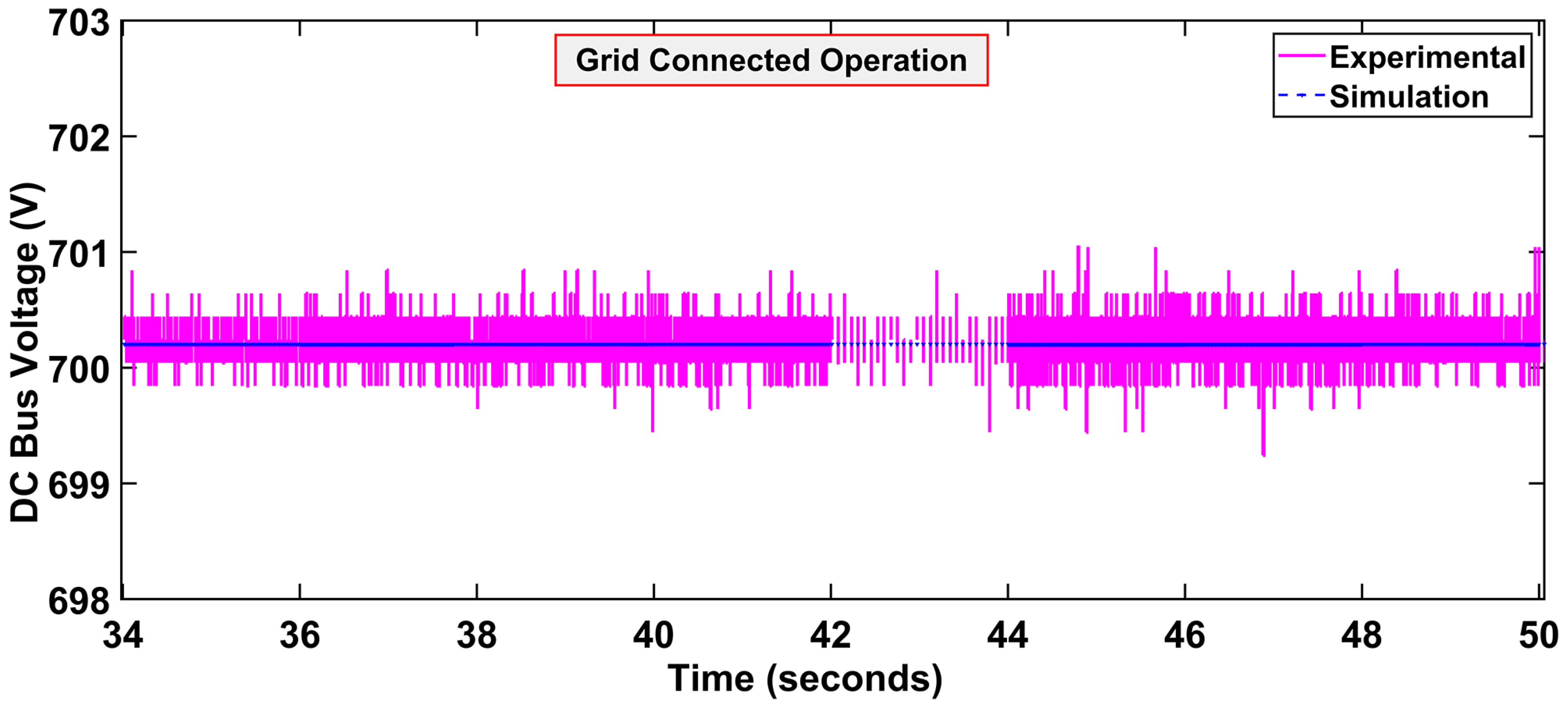
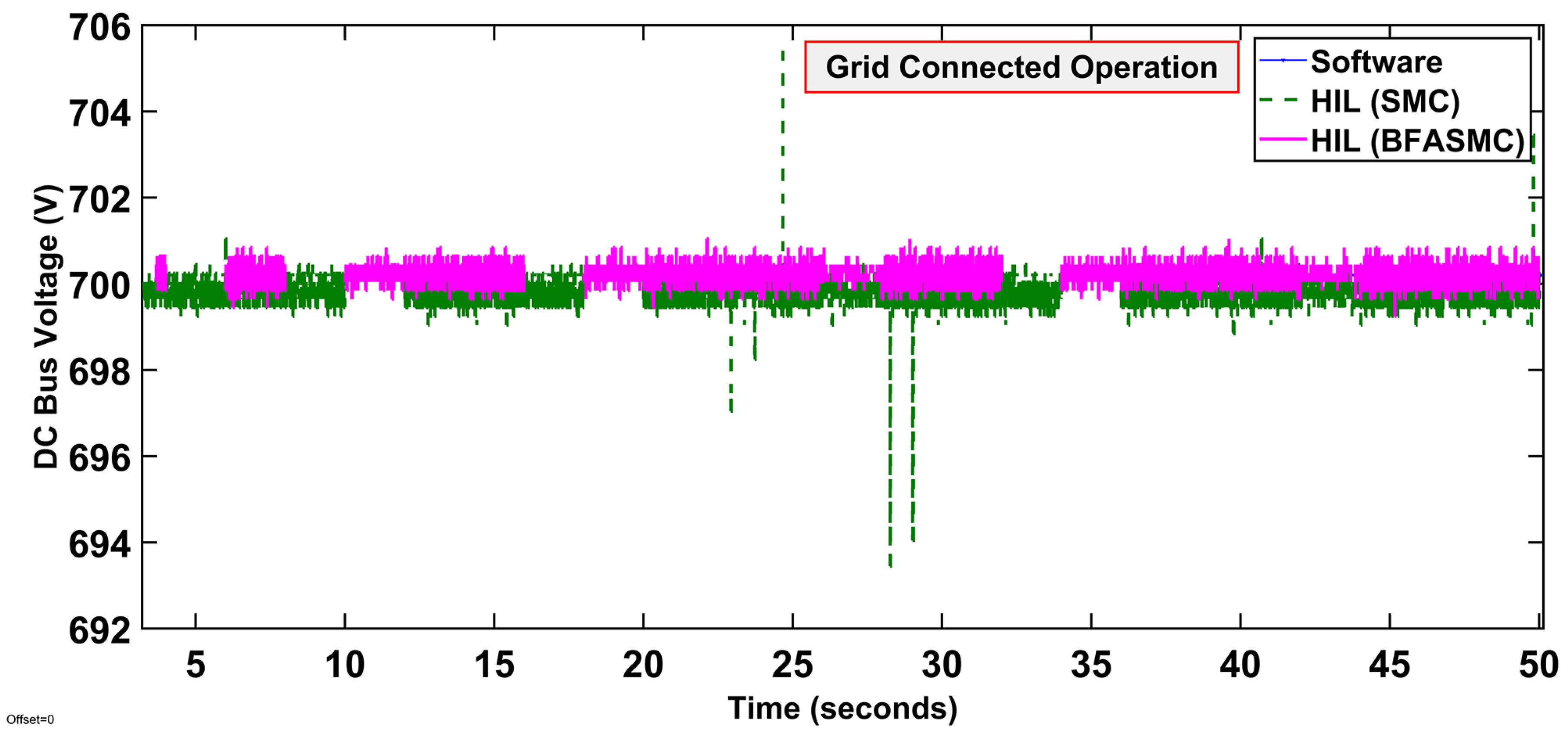
4.3.2. Grid-Connected Operation

Figure 22 represents close-loop HIL regulation of the DC bus during the grid-connected mode. The experimental result shows some fluctuation in voltages from 699.8 V to 700.3 V, which is under the acceptable range. Moreover, a comparison of simulation and experimental results validate the adequate performance of the BFASMC controller. In Figure 23, HIL BFASMC DC bus voltage regulation comparison is presented with HIL-SMC during the grid-connected mode. Results show that SMC has a large overshoot and does not track the voltage accurately, where BFASMC has less overshoot and regulates the DC bus more precisely.

5. Conclusions and Future Work

This manuscript provides a barrier function-based adaptive sliding mode controller approach for a hybrid AC/DC microgrid considering the islanded and grid-connected operations. MATLAB/Simulink evaluates the performance of the proposed technique under different cases and results reveal the better performance than PID, SMC, and Lyapunov. The main performance objective of the proposed approach to ensure the stability of AC and DC sub-grids during the grid-connected and islanded mode has been accomplished successfully and efficiently. Finally, the hardware-in-loop execution of the proposed structure further validates the real-time performance of the controller. Results under different experiments indicate the stable operation of the DC bus during the varying output from the RESs and OFF/ON grid modes. Future work may involve the real microgrid framework in the laboratory, where, proposed controller technique can be tested through various real-time experimental assessments.

Author Contributions

Conceptualization and investigation, A.A.; writing-original draft, Methodology, M.H. and H.A.; supervision and project administration, M.Y.; writing-review and editing, N.A. and F.A.; software and visualization, M.K.A. All authors have read and agreed to the published version of the manuscript.

Funding

The authors extend their appreciation to the Deputyship for Research Innovation, Ministry of Education in Saudi Arabia for supporting this work through the project number “375213500”. The authors also would like to extend their sincere appreciation to the central laboratory at Jouf University for supporting this study.

Institutional Review Board Statement

Not applicable.

Informed Consent Statement

Not applicable.

Data Availability Statement

Not applicable.

Conflicts of Interest

The authors declare no conflict of interest.

References

  1. Bull, S.R. Renewable energy today and tomorrow. Proc. IEEE 2001, 89, 1216–1226. [Google Scholar] [CrossRef]
  2. Lasseter, R.H.; Paigi, P. Microgrid: A conceptual solution. In Proceedings of the 2004 IEEE 35th Annual Power Electronics Specialists Conference (IEEE Cat. No. 04CH37551), Aachen, Germany, 20–25 June 2004; Volume 6, pp. 4285–4290. [Google Scholar]
  3. Benson, C.L.; Magee, C.L. On improvement rates for renewable energy technologies: Solar PV, wind turbines, capacitors, and batteries. Renew. Energy 2014, 68, 745–751. [Google Scholar] [CrossRef]
  4. Bari, A.; Jiang, J.; Saad, W.; Jaekel, A. Challenges in the smart grid applications: An overview. Int. J. Distrib. Sens. Netw. 2014, 10, 974682. [Google Scholar] [CrossRef] [Green Version]
  5. Luna, A.C.; Diaz, N.L.; Graells, M.; Vasquez, J.C.; Guerrero, J.M. Mixed-integer-linear-programming-based energy management system for hybrid PV-wind-battery microgrids: Modeling, design, and experimental verification. IEEE Trans. Power Electron. 2016, 32, 2769–2783. [Google Scholar] [CrossRef] [Green Version]
  6. Khare, V.; Nema, S.; Baredar, P. Solar–wind hybrid renewable energy system: A review. Renew. Sustain. Energy Rev. 2016, 58, 23–33. [Google Scholar] [CrossRef]
  7. Atia, R.; Yamada, N. Sizing and analysis of renewable energy and battery systems in residential microgrids. IEEE Trans. Smart Grid 2016, 7, 1204–1213. [Google Scholar] [CrossRef]
  8. Elsayed, A.T.; Mohamed, A.A.; Mohammed, O.A. DC microgrids and distribution systems: An overview. Electr. Power Syst. Res. 2015, 119, 407–417. [Google Scholar] [CrossRef]
  9. Alanazi, A.; Lotfi, H.; Khodaei, A. Coordinated AC/DC microgrid optimal scheduling. In Proceedings of the 2017 North American Power Symposium (NAPS), Morgantown, WV, USA, 17–19 September 2017; pp. 1–6. [Google Scholar]
  10. Zhou, X.; Zhou, L.; Chen, Y.; Guerrero, J.M.; Luo, A.; Wu, W.; Yang, L. A microgrid cluster structure and its autonomous coordination control strategy. Int. J. Electr. Power Energy Syst. 2018, 100, 69–80. [Google Scholar] [CrossRef]
  11. Wang, P.; Goel, L.; Liu, X.; Choo, F.H. Harmonizing AC and DC: A hybrid AC/DC future grid solution. IEEE Power Energy Mag. 2013, 11, 76–83. [Google Scholar] [CrossRef]
  12. Pourbehzadi, M.; Niknam, T.; Aghaei, J.; Mokryani, G.; Shafie-khah, M.; Catalão, J.P. Optimal operation of hybrid AC/DC microgrids under uncertainty of renewable energy resources: A comprehensive review. Int. J. Electr. Power Energy Syst. 2019, 109, 139–159. [Google Scholar] [CrossRef]
  13. Yang, P.; Xia, Y.; Yu, M.; Wei, W.; Peng, Y. A decentralized coordination control method for parallel bidirectional power converters in a hybrid AC–DC microgrid. IEEE Trans. Ind. Electron. 2017, 65, 6217–6228. [Google Scholar] [CrossRef]
  14. Hosseinzadeh, M.; Salmasi, F.R. Power management of an isolated hybrid AC/DC micro-grid with fuzzy control of battery banks. IET Renew. Power Gener. 2015, 9, 484–493. [Google Scholar] [CrossRef]
  15. Merabet, A.; Ahmed, K.T.; Ibrahim, H.; Beguenane, R.; Ghias, A.M. Energy management and control system for laboratory scale microgrid based wind-PV-battery. IEEE Trans. Sustain. Energy 2016, 8, 145–154. [Google Scholar] [CrossRef]
  16. Hu, J.; Shan, Y.; Xu, Y.; Guerrero, J.M. A coordinated control of hybrid ac/dc microgrids with PV-wind-battery under variable generation and load conditions. Int. J. Electr. Power Energy Syst. 2019, 104, 583–592. [Google Scholar] [CrossRef] [Green Version]
  17. Iovine, A.; Siad, S.B.; Damm, G.; De Santis, E.; Di Benedetto, M.D. Nonlinear control of a dc microgrid for the integration of photovoltaic panels. IEEE Trans. Autom. Sci. Eng. 2017, 14, 524–535. [Google Scholar] [CrossRef] [Green Version]
  18. Armghan, H.; Yang, M.; Wang, M.; Ali, N.; Armghan, A. Nonlinear integral backstepping based control of a DC microgrid with renewable generation and energy storage systems. Int. J. Electr. Power Energy Syst. 2020, 117, 105613. [Google Scholar] [CrossRef]
  19. Mohamed, Y.A.R.I.; Zeineldin, H.H.; Salama, M.; Seethapathy, R. Seamless formation and robust control of distributed generation microgrids via direct voltage control and optimized dynamic power sharing. IEEE Trans. Power Electron. 2011, 27, 1283–1294. [Google Scholar] [CrossRef]
  20. Kumar, M.; Srivastava, S.; Singh, S. Control strategies of a DC microgrid for grid connected and islanded operations. IEEE Trans. Smart Grid 2015, 6, 1588–1601. [Google Scholar] [CrossRef]
  21. Singh, S.; Fulwani, D.; Kumar, V. Robust sliding-mode control of dc/dc boost converter feeding a constant power load. IET Power Electron. 2015, 8, 1230–1237. [Google Scholar] [CrossRef]
  22. Kim, J.; Guerrero, J.M.; Rodriguez, P.; Teodorescu, R.; Nam, K. Mode adaptive droop control with virtual output impedances for an inverter-based flexible AC microgrid. IEEE Trans. Power Electron. 2010, 26, 689–701. [Google Scholar] [CrossRef]
  23. Han, H.; Hou, X.; Yang, J.; Wu, J.; Su, M.; Guerrero, J.M. Review of power sharing control strategies for islanding operation of AC microgrids. IEEE Trans. Smart Grid 2015, 7, 200–215. [Google Scholar] [CrossRef] [Green Version]
  24. Rocabert, J.; Luna, A.; Blaabjerg, F.; Rodriguez, P. Control of power converters in AC microgrids. IEEE Trans. Power Electron. 2012, 27, 4734–4749. [Google Scholar] [CrossRef]
  25. Cai, H.; Hu, G.; Lewis, F.L.; Davoudi, A. A distributed feedforward approach to cooperative control of AC microgrids. IEEE Trans. Power Syst. 2015, 31, 4057–4067. [Google Scholar] [CrossRef]
  26. Guerrero, J.M.; Vasquez, J.C.; Matas, J.; De Vicuña, L.G.; Castilla, M. Hierarchical control of droop-controlled AC and DC microgrids—A general approach toward standardization. IEEE Trans. Ind. Electron. 2010, 58, 158–172. [Google Scholar] [CrossRef]
  27. Liang, B.; Kang, L.; He, J.; Zheng, F.; Xia, Y.; Zhang, Z.; Zhang, Z.; Liu, G.; Zhao, Y. Coordination control of hybrid AC/DC microgrid. J. Eng. 2019, 2019, 3264–3269. [Google Scholar] [CrossRef]
  28. Armghan, H.; Yang, M.; Armghan, A.; Ali, N.; Wang, M.; Ahmad, I. Design of integral terminal sliding mode controller for the hybrid AC/DC microgrids involving renewables and energy storage systems. Int. J. Electr. Power Energy Syst. 2020, 119, 105857. [Google Scholar] [CrossRef]
  29. Liu, X.; Wang, P.; Loh, P.C. A hybrid AC/DC microgrid and its coordination control. IEEE Trans. Smart Grid 2011, 2, 278–286. [Google Scholar]
  30. Loh, P.C.; Li, D.; Chai, Y.K.; Blaabjerg, F. Autonomous operation of hybrid microgrid with AC and DC subgrids. IEEE Trans. Power Electron. 2012, 28, 2214–2223. [Google Scholar] [CrossRef]
  31. Babazadeh, M.; Karimi, H. A robust two-degree-of-freedom control strategy for an islanded microgrid. IEEE Trans. Power Deliv. 2013, 28, 1339–1347. [Google Scholar] [CrossRef]
  32. Kakigano, H.; Miura, Y.; Ise, T. Distribution voltage control for DC microgrids using fuzzy control and gain-scheduling technique. IEEE Trans. Power Electron. 2012, 28, 2246–2258. [Google Scholar] [CrossRef]
  33. Vasquez, J.C.; Guerrero, J.M.; Luna, A.; Rodríguez, P.; Teodorescu, R. Adaptive droop control applied to voltage-source inverters operating in grid-connected and islanded modes. IEEE Trans. Ind. Electron. 2009, 56, 4088–4096. [Google Scholar] [CrossRef]
  34. Li, P.; Guo, T.; Zhou, F.; Yang, J.; Liu, Y. Nonlinear coordinated control of parallel bidirectional power converters in an AC/DC hybrid microgrid. Int. J. Electr. Power Energy Syst. 2020, 122, 106208. [Google Scholar] [CrossRef]
  35. Ma, T.; Cintuglu, M.H.; Mohammed, O.A. Control of a hybrid AC/DC microgrid involving energy storage and pulsed loads. IEEE Trans. Ind. Appl. 2016, 53, 567–575. [Google Scholar] [CrossRef]
  36. Tummuru, N.R.; Mishra, M.K.; Srinivas, S. Dynamic energy management of renewable grid integrated hybrid energy storage system. IEEE Trans. Ind. Electron. 2015, 62, 7728–7737. [Google Scholar] [CrossRef]
  37. Iovine, A.; Siad, S.B.; Damm, G.; De Santis, E.; Di Benedetto, M.D. Nonlinear control of an AC-connected DC MicroGrid. In Proceedings of the IECON 2016-42nd Annual Conference of the IEEE Industrial Electronics Society, Florence, Italy, 23–26 October 2016; pp. 4193–4198. [Google Scholar]
  38. Armghan, H.; Yang, M.; Armghan, A.; Ali, N. Double integral action based sliding mode controller design for the back-to-back converters in grid-connected hybrid wind-PV system. Int. J. Electr. Power Energy Syst. 2021, 127, 106655. [Google Scholar] [CrossRef]
  39. Cook, M.D.; Parker, G.G.; Robinett, R.D.; Weaver, W.W. Decentralized mode-adaptive guidance and control for DC microgrid. IEEE Trans. Power Deliv. 2016, 32, 263–271. [Google Scholar] [CrossRef]
  40. Armghan, A.; Azeem, M.K.; Armghan, H.; Yang, M.; Alenezi, F.; Hassan, M. Dynamical Operation Based Robust Nonlinear Control of DC Microgrid Considering Renewable Energy Integration. Energies 2021, 14, 3988. [Google Scholar] [CrossRef]
  41. Hassan, M.; Paracha, Z.J.; Armghan, H.; Ali, N.; Said, H.A.; Farooq, U.; Afzal, A.; Hassan, M.A.S. Lyapunov based adaptive controller for power converters used in hybrid energy storage systems. Sustain. Energy Technol. Assess. 2020, 42, 100853. [Google Scholar]
  42. Iovine, A.; Carrizosa, M.J.; Damm, G.; Alou, P. Nonlinear control for DC microgrids enabling efficient renewable power integration and ancillary services for AC grids. IEEE Trans. Power Syst. 2018, 34, 5136–5146. [Google Scholar] [CrossRef]
  43. Abdullah, M.A.; Yatim, A.; Tan, C.W.; Saidur, R. A review of maximum power point tracking algorithms for wind energy systems. Renew. Sustain. Energy Rev. 2012, 16, 3220–3227. [Google Scholar] [CrossRef]
  44. Armghan, H.; Ahmad, I.; Armghan, A.; Khan, S.; Arsalan, M. Backstepping based non-linear control for maximum power point tracking in photovoltaic system. Sol. Energy 2018, 159, 134–141. [Google Scholar]
  45. Han, Y.; Ma, R.; Cui, J. Adaptive higher-order sliding mode control for islanding and grid-connected operation of a microgrid. Energies 2018, 11, 1459. [Google Scholar] [CrossRef] [Green Version]
  46. Obeid, H.; Fridman, L.M.; Laghrouche, S.; Harmouche, M. Barrier function-based adaptive sliding mode control. Automatica 2018, 93, 540–544. [Google Scholar] [CrossRef]
Figure 1. Hybrid AC/DC Microgrid.
Applsci 11 08672 g001
Figure 2. Wind energy system configuration.
Applsci 11 08672 g002
Figure 3. PV energy system configuration.
Applsci 11 08672 g003
Figure 4. Battery bank configuration.
Applsci 11 08672 g004
Figure 5. AC subgrid configuration.
Applsci 11 08672 g005
Figure 6. AC/DC configuration of proposed MG.
Applsci 11 08672 g006
Figure 7. General structure of the controller.
Applsci 11 08672 g007
Figure 8. (a) Wind Speed Profile (b) Load Power Profile.
Applsci 11 08672 g008
Figure 9. Islanded mode (a) Power of energy sources (b) DC bus voltage.
Applsci 11 08672 g009
Figure 10. DC bus voltage comparison during islanded mode.
Applsci 11 08672 g010
Figure 11. Power generated by wind and PV system.
Applsci 11 08672 g011
Figure 12. DC bus during grid connection.
Applsci 11 08672 g012
Figure 13. DC bus comparison during grid connection.
Applsci 11 08672 g013
Figure 14. Frequency regulation at the VSI side.
Applsci 11 08672 g014
Figure 15. Grid current during grid-connected mode.
Applsci 11 08672 g015
Figure 16. Grid voltage during grid-connected mode.
Applsci 11 08672 g016
Figure 17. Frequency comparison.
Applsci 11 08672 g017
Figure 18. Grid current comparison.
Applsci 11 08672 g018
Figure 19. HIL setup.
Applsci 11 08672 g019
Figure 20. DC bus voltage during islanded mode.
Applsci 11 08672 g020
Figure 21. HIL DC bus comparison islanded mode.
Applsci 11 08672 g021
Figure 22. DC bus voltage during grid-connected mode.
Applsci 11 08672 g022
Figure 23. HIL DC bus comparison grid-connected mode.
Applsci 11 08672 g023
Table 1. Parameters of PV energy system.
Irradiance (W/m 2 )Temperature (°C)V MPP (V)
64021294
70026286
80031.6281
90037.4270
100042266
85536273
74033278
61530281
51527.2287
44525288
Table 2. Parameters of energy sources.
PV Parameters
Photo Voltaic module10 per string
Parallel linked strings1
Cells per module60
OC voltage363 V
SC Current7.84 A
Maximum power point voltage ( V m p p )290 V
Maximum power point current ( I m p p )7.35 A
Nominal power ouptput capacity2.1 kW
Wind System Parameters
Air density1.225 kg/m 3
Wind speed5 m/s
Rotor diameter5.5 m
λ o p t 7.5
C p m a x 0.43
PMSG
Rated power3 kW
Stator resistance0.036 ohm
Stator d-axis inductance0.334  mH
Stator q-axis inductance0.217 mh
Number of pole pairs4
Flux linkage0.192 Wb
Moment of inertia0.011 kg m 2
Viscos damping0.001889 N ms
Table 3. Battery Parameters.
ParameterValue
Battery typeLithium-Ion (Li-Ion)
Voltage190–540 V
Rated current capacity33.9 Ah
Maximum charge current17.5 A
Maximum discharge current30 A
Table 4. Simulation Parameters.
Circuit Parameters
l w , L p v , L b a t 20 mH, 20 mH, 3.3 mH,
C d c , C w , C p v , C p o u t 16 uF, 68 uF, 16 uF, 68 uF,
Switching Frequency100 kHz
Control System (BFASMC)
ε 1 , ε 2 , ε 3 , ε 4 , ε 5 , ε 6 , ε 7 , ε 8 10,000, 10,000, 30,000,8500, 10,000, 10,000, 3500, 15,000
F ¯ 1000 to 3000
c 2 2000
SMC
a 1 , a 2 , a 3 , α 4 , α 5 1500, 1000, 2000,500,1500
c 2 2000
Lyapunov Controller
b 1 , b 2 , b 3 , b 4 , b 5 1000, 2000, 1000, 1500, 2500
c 2 2000
PID
k 1 , k 2 , k 3 10,130,28
Table 5. Comparison Table.
ModeControllersRise Time (s)Settling Time (s)Overshoot (%)Steady State Error (SSE)%
Lyapunov0.050.52.10.2
IslandedPID0.50.6150.2
SMC0.0350.0514.70.5
BFASMC0.00250.030.10.03
Grid-ConnectedLyapunov0.50.20.29Nil
BFASMC0.0350.00030.1Nil
SMC0.30.00150.5
Publisher’s Note: MDPI stays neutral with regard to jurisdictional claims in published maps and institutional affiliations.

