
Blast Loaded Columns—State of the Art Review


Abstract
:1. Introduction
2. Experimental Testing
2.1. Bridge Columns
- Using protective fences and barriers for vehicles to increase the standoff distance;
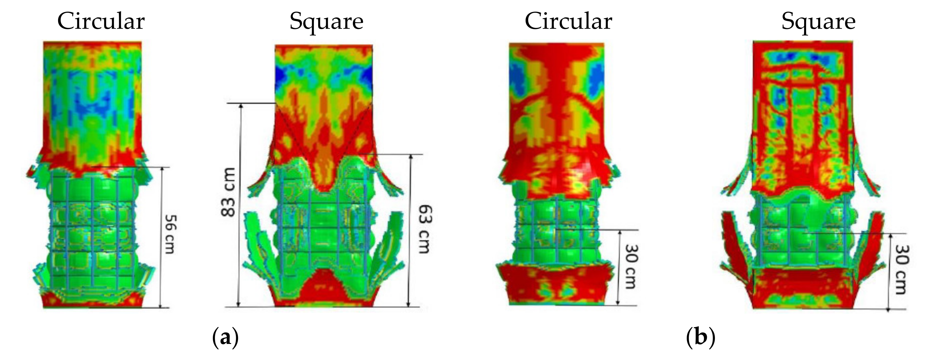
- The circular cross-section can maintain a lower pressure of up to 1/3 concerning a square cross-section of the same dimensions, so the second guideline is to use circular columns, and also, the pressure reducing factors on the circular column were proposed by Winget et al. [2], Marchand et al. [36], and Fujikura et al. [7], respectively, as 0.80, 0.75, and 0.45;
- Increase in the reinforcement in the column, as this increases the shear capacity, ductility, and confinement of the concrete;
- Use of continuous reinforcement because discrete hoops can be extracted during a blast load;
- Placing longitudinal splices away from the charge if they cannot be completely avoided.
2.2. Building Columns
3. Numerical Modeling
4. Discussion and Conclusions
4.1. Experimental Testing
4.2. Numerical Modeling
Author Contributions
Funding
Institutional Review Board Statement
Informed Consent Statement
Data Availability Statement
Acknowledgments
Conflicts of Interest
References
- START. National Consortium for the Study of Terrorism and Responses to Terrorism. Global Terrorism Database. 2017. Available online: https://www.start.umd.edu/gtd/ (accessed on 20 May 2020).
- Winget, D.G.; Marchand, K.A.; Williamson, E.B. Analysis and design of critical bridges subjected to blast loads. J. Struct. Eng. 2005, 131, 1243–1255. [Google Scholar] [CrossRef]
- Cooper, J.D.; Smith, M.C.; Ernst, S.L. Blue Ribbon Panel Recommendation for Bridge and Tunnel Security; The American Association of State Highway and Transportation Officials (AASHTO): Washington, DC, USA, 2003. [Google Scholar]
- Williamson, E.B.; Bayrak, O.; Davis, C.; Williams, G.D. Performance of bridge columns subjected to blast loads. I: Experimental program. J. Bridge Eng. 2011, 16, 693–702. [Google Scholar] [CrossRef]
- Fouché, P.; Bruneau, M.; Chiarito, V.P. Modified steel-jacketed columns for combined blast and seismic retrofit of existing bridge columns. J. Bridge Eng. 2016, 21, 4016035. [Google Scholar] [CrossRef] [Green Version]
- Bruneau, M.; Lopez-Garcia, D.; Fujikura, S. Multihazard-resistant highway bridge bent. In Proceedings of the Structures Congress 2006: Structural Engineering and Public Safety, St. Louis, MN, USA, 18–21 May 2006; pp. 1–4. [Google Scholar]
- Fujikura, S.; Bruneau, M.; Lopez-Garcia, D. Experimental investigation of multihazard resistant bridge piers having concrete-filled steel tube under blast loading. J. Bridge Eng. 2008, 13, 586–594. [Google Scholar] [CrossRef]
- Davis, C.E.; Williams, G.D.; Williamson, E.B.; Marchand, K.A.; McKay, A.E.; Bayrak, O. Design and detailing guidelines for bridge columns subjected to blast and other extreme loads. In Proceedings of the Structures Congress 2009: Don’t Mess with Structural Engineers: Expanding Our Role, Austin, TX, USA, 30 April–2 May 2009; pp. 1–10. [Google Scholar]
- Fujikura, S.; Bruneau, M. Experimental investigation of seismically resistant bridge piers under blast loading. J. Bridge Eng. 2010, 16, 63–71. [Google Scholar] [CrossRef]
- Crawford, J.E. State of the art for enhancing the blast resistance of reinforced concrete columns with fiber-reinforced plastic. Can. J. Civil Eng. 2013, 40, 1023–1033. [Google Scholar] [CrossRef]
- Burrell, R.P.; Aoude, H.; Saatcioglu, M. Response of SFRC columns under blast loads. J. Struct. Eng. 2015, 141, 4014209. [Google Scholar] [CrossRef]
- Zhang, F.; Wu, C.; Wang, H.; Zhou, Y. Numerical simulation of concrete filled steel tube columns against BLAST loads. Thin Walled Struct. 2015, 92, 82–92. [Google Scholar] [CrossRef]
- Aoude, H.; Dagenais, F.P.; Burrell, R.P.; Saatcioglu, M. Behavior of ultra-high performance fiber reinforced concrete columns under blast loading. Int. J. Impact Eng. 2015, 80, 185–202. [Google Scholar] [CrossRef]
- Codina, R.; Ambrosini, D.; de Borbón, F. Experimental and numerical study of a RC member under a close-in blast loading. Eng. Struct. 2016, 127, 145–158. [Google Scholar] [CrossRef]
- Codina, R.; Ambrosini, D.; de Borbón, F. Alternatives to prevent the failure of RC members under close-in blast loadings. Eng. Fail. Anal. 2016, 60, 96–106. [Google Scholar] [CrossRef]
- Codina, R.; Ambrosini, D.; de Borbon, F. Alternatives to prevent progressive collapse protecting reinforced concrete columns subjected to near field blast loading. Procedia Eng. 2017, 199, 2445–2450. [Google Scholar] [CrossRef]
- Xu, J.; Wu, C.; Xiang, H.; Su, Y.; Li, Z.-X.; Fang, Q.; Hao, H.; Liu, Z.; Zhang, Y.; Li, J. Behaviour of ultra high performance fibre reinforced concrete columns subjected to blast loading. Eng. Struct. 2016, 118, 97–107. [Google Scholar] [CrossRef]
- Echevarria, A.; Zaghi, A.E.; Chiarito, V.; Christenson, R.; Woodson, S. Experimental comparison of the performance and residual capacity of CFFT and RC bridge columns subjected to blasts. J. Bridge Eng. 2016, 21, 4015026. [Google Scholar] [CrossRef]
- Wang, J.; Chen, W.; Guo, Z.; Liang, W. Dynamic responses of RPC-filled steel tubular columns post fire under blast loading. Open Civil Eng. J. 2016, 10, 236–245. [Google Scholar] [CrossRef]
- Zhang, F.; Wu, C.; Zhao, X.-L.; Xiang, H.; Li, Z.-X.; Fang, Q.; Liu, Z.; Zhang, Y.; Heidarpour, A.; Packer, J.A. Experimental study of CFDST columns infilled with UHPC under close-range blast loading. Int. J. Impact Eng. 2016, 93, 184–195. [Google Scholar] [CrossRef]
- Zhang, F.; Wu, C.; Zhao, X.-L.; Heidarpour, A.; Li, Z. Experimental and numerical study of blast resistance of square CFDST columns with steel-fibre reinforced concrete. Eng. Struct. 2017, 149, 50–63. [Google Scholar] [CrossRef]
- Codina, R.; Ambrosini, D.; de Borbón, F. New sacrificial cladding system for the reduction of blast damage in reinforced concrete structures. Int. J. Prot. Struct. 2017, 8, 221–236. [Google Scholar] [CrossRef]
- Yuan, S.; Hao, H.; Zong, Z.; Li, J. A study of RC bridge columns under contact explosion. Int. J. Impact Eng. 2017, 109, 378–390. [Google Scholar] [CrossRef]
- Wang, H.; Wu, C.; Zhang, F.; Fang, Q.; Xiang, H.; Li, P.; Li, Z.; Zhou, Y.; Zhang, Y.; Li, J. Experimental study of large-sized concrete filled steel tube columns under blast load. Constr. Build. Mater. 2017, 134, 131–141. [Google Scholar] [CrossRef]
- Li, J.; Wu, C.; Hao, H.; Liu, Z. Post-blast capacity of ultra-high performance concrete columns. Eng. Struct. 2017, 134, 289–302. [Google Scholar] [CrossRef]
- Fouché, P.; Bruneau, M.; Chiarito, V. Dual-hazard blast and seismic behavior of concrete-filled double-skin steel tubes bridge pier. J. Struct. Eng. 2017, 143, 4017155. [Google Scholar] [CrossRef] [Green Version]
- Dua, A.; Braimah, A.; Kumar, M. Contact explosion response of reinforced concrete columns: Experimental and validation of numerical model. In Proceedings of the Paper presented at the 6th International Disaster Mitigation Specialty Conference, Fredericton, NB, Canada, 13–16 June 2018. [Google Scholar]
- Dua, A.; Braimah, A.; Kumar, M. Experimental and numerical investigation of rectangular reinforced concrete columns under contact explosion effects. Eng. Struct. 2020, 205, 109891. [Google Scholar] [CrossRef]
- Wang, Z.; Wu, H.; Fang, Q.; Wu, J. Experimental study on the residual axial capacity of ultra high performance cementitious composite filled steel tube (UHPCC-FST) column under contact explosion. Thin Walled Struct. 2020, 147, 106515. [Google Scholar] [CrossRef]
- Kadhom, B.; Almansour, H.; Saatcioglu, M. Post-blast axial capacity of CFRP strengthened RC columns. In IOP Conference Series: Materials Science and Engineering, Proceedings of the 4th International Conference on Buildings, Construction and Environmental Engineering, Istanbul, Turkey, 7–9 October 2019; IOP Publishing Ltd.: Istanbul, Turkey, 2020; p. 012042. [Google Scholar]
- Vapper, M.; Lasn, K. Blast protection of concrete columns with thin strips of GFRP overlay. Structures 2020, 25, 491–499. [Google Scholar] [CrossRef]
- Williamson, E.B.; Winget, D.G. Risk management and design of critical bridges for terrorist attacks. J. Bridge Eng. 2005, 10, 96–106. [Google Scholar] [CrossRef]
- Chipley, M. Reference Manual to Mitigate Potential Terrorist Attacks Against Buildings: Providing Protection to People and Building; Federal Emergency Management Agency: Washington, DC, USA, 2003.
- Roberts, J.; Kulicki, J.; Beranek, D.A.; Englot, J.M.; Fisher, J.W.; Hungerbeeler, H.; Seible, F.; Stinson, K.; Tang, M.C.; Witt, K. Recommendations for Bridge and Tunnel Security; Federal Highway Administration (US): Washington, DC, USA, 2003.
- Williamson, E.B.; Bayrak, O.; Davis, C.; Daniel Williams, G. Performance of bridge columns subjected to blast loads. II: Results and recommendations. J. Bridge Eng. 2011, 16, 703–710. [Google Scholar] [CrossRef]
- Marchand, K.; Williamson, E.; Winget, D. Analysis of blast loads on bridge substructures. WIT Trans. Built Environ. 2004, 73. [Google Scholar] [CrossRef]
- National Cooperative Highway Research Program. Blast-Resistant Highway Bridges: Design and Detailing Guidelines; Transportation Research Board: Washington, DC, USA, 2010. [Google Scholar]
- Williams, G.; Holland, C.; Williamson, E.B.; Bayrak, O.; Marchand, K.A.; Ray, J. Blast-Resistant Highway Bridges: Design and Detailing Guidelines; Transportation Research Board; WIT Press: Southampton, UK, 2010; Volume 645. [Google Scholar]
- Conrath, E.J. Structural Design for Physical Security: State of the Practice; ASCE, cop.: Reston, VA, USA, 1999. [Google Scholar]
- Mays, G.; Smith, P.D.; Smith, P.D. Blast Effects on Buildings: Design of Buildings to Optimize Resistance to Blast Loading; Thomas Telford: Telford, UK, 1995. [Google Scholar]
- US DoD. UFC 3-340-02: Structures to Resist the Effects of Accidental Explosions; US DoD.: Washington, DC, USA, 2008.
- American Institute of Steel Construction. Seismic Provisions for Structural Steel Buildings; American Institute of Steel Construction: Chicago, IL, USA, 2010. [Google Scholar]
- Fujikake, K.; Aemlaor, P. Damage of reinforced concrete columns under demolition blasting. Eng. Struct. 2013, 55, 116–125. [Google Scholar] [CrossRef]
- Roller, C.; Mayrhofer, C.; Riedel, W.; Thoma, K. Residual load capacity of exposed and hardened concrete columns under explosion loads. Eng. Struct. 2013, 55, 66–72. [Google Scholar] [CrossRef]
- Xu, K.; Deng, Q.; Cai, L.; Ho, S.; Song, G. Damage detection of a concrete column subject to blast loads using embedded piezoceramic transducers. Sensors 2018, 18, 1377. [Google Scholar] [CrossRef] [PubMed] [Green Version]
- Ray, J.; Armstrong, B.; Slawson, T. Airblast environment beneath a bridge overpass. Transp. Res. Rec. J. Transp. Res. Board 2003, 1827, 63–68. [Google Scholar] [CrossRef]
- Rutner, M.P.; Astaneh-Asl, A.; Son, J. Blast resistant performance of steel and composite bridge piers. In Proceedings of the IABSE Symposium Report, Munich, Germany, 29 August–1 September 2005; pp. 47–54. [Google Scholar]
- Wu, K.-C.; Li, B.; Tsai, K.-C. The effects of explosive mass ratio on residual compressive capacity of contact blast damaged composite columns. J. Constr. Steel Res. 2011, 67, 602–612. [Google Scholar] [CrossRef]
- Hao, H.; Stewart, M.G.; Li, Z.-X.; Shi, Y. RC column failure probabilities to blast loads. Int. J. Prot. Struct. 2010, 1, 571–591. [Google Scholar] [CrossRef]
- Elsanadedy, H.M.; Almusallam, T.H.; Abbas, H.; Al-Salloum, Y.A.; Alsayed, S.H. Effect of blast loading on CFRP-Retrofitted RC columns-a numerical study. Lat. Am. J. Solids Struct. 2011, 8, 55–81. [Google Scholar] [CrossRef] [Green Version]
- Williams, G.D.; Williamson, E.B. Response of reinforced concrete bridge columns subjected to blast loads. J. Struct. Eng. 2011, 137, 903–913. [Google Scholar] [CrossRef]
- Williams, G.D.; Williamson, E.B. Procedure for predicting blast loads acting on bridge columns. J. Bridge Eng. 2011, 17, 490–499. [Google Scholar] [CrossRef]
- Magali, A.; Alain, R.; Chhim, S. Numerical dynamic simulations for the prediction of damage and loss of capacity of RC column subjected to contact detonations. In Fracture Mechanics of Concrete and Concrete Structures; IA-FraMCoS: Toledo, Spain, 2013. [Google Scholar]
- Eisa, A.S. Finite element analysis of reinforced concrete columns under different range of blast loads. Int. J. Civ. Struct. Eng. 2014, 5, 155. [Google Scholar]
- Abladey, L.; Braimah, A. Near-field explosion effects on the behaviour of reinforced concrete columns: A numerical investigation. Int. J. Prot. Struct. 2014, 5, 475–499. [Google Scholar] [CrossRef]
- Li, J.; Hao, H. Numerical study of concrete spall damage to blast loads. Int. J. Impact Eng. 2014, 68, 41–55. [Google Scholar] [CrossRef]
- Shi, Y.; Stewart, M.G. Spatial reliability analysis of explosive blast load damage to reinforced concrete columns. Struct. Saf. 2015, 53, 13–25. [Google Scholar] [CrossRef]
- Liu, H.; Torres, D.M.; Agrawal, A.K.; Yi, Z.; Liu, G. Simplified blast-load effects on the column and bent beam of highway bridges. J. Bridge Eng. 2015, 20, 06015001. [Google Scholar] [CrossRef]
- Cui, J.; Shi, Y.; Li, Z.-X.; Chen, L. Failure analysis and damage assessment of RC columns under close-in explosions. J. Perform. Constr. Facil. 2015, 29, B4015003. [Google Scholar] [CrossRef]
- Arowojolu, O.; Rahman, M.K.; Hussain, B.M. Dynamic response of reinforced concrete bridge piers subjected to combined axial and blast loading. In Proceedings of the Structures Congress 2017, Denver, CO, USA, 6–8 April 2017; pp. 98–109. [Google Scholar]
- Eamon, C.; Alsendi, A. Resistance of Reinforced Concrete Bridge Columns Subjected to Blast Loads. 2017. Available online: http://www.awarie.zut.edu.pl/files/ab2017/referaty/09/09-02%20-%20Eamon%20C,%20Aslendi%20A%20-%20Resistance%20of%20reinforced%20concrete%20bridge%20columns%20subjected%20to%20blast%20loads.pdf (accessed on 1 June 2021).
- Kravchenko, G.; Trufanova, E.; Kostenko, D.; Tsurikov, S. Analysis of blast load on a reinforced concrete column in the time domain. MATEC Web Conf. 2017, 106, 04019. [Google Scholar] [CrossRef] [Green Version]
- Kyei, C.; Braimah, A. Effects of transverse reinforcement spacing on the response of reinforced concrete columns subjected to blast loading. Eng. Struct. 2017, 142, 148–164. [Google Scholar] [CrossRef]
- Abedini, M.; Mutalib, A.A.; Raman, S.N.; Akhlaghi, E. Modeling the effects of high strain rate loading on RC columns using Arbitrary Lagrangian Eulerian (ALE) technique. Rev. Int. Métodos Numéricos Cálculo Diseño Ing. 2018, 34. [Google Scholar] [CrossRef]
- Li, M.; Zong, Z.; Liu, L.; Lou, F. Experimental and numerical study on damage mechanism of CFDST bridge columns subjected to contact explosion. Eng. Struct. 2018, 159, 265–276. [Google Scholar] [CrossRef]
- Liu, L.; Zong, Z.; Li, M. Numerical study of damage modes and assessment of circular RC pier under noncontact explosions. J. Bridge Eng. 2018, 23, 04018061. [Google Scholar] [CrossRef]
- Li, M.; Zong, Z.; Hao, H.; Zhang, X.; Lin, J.; Xie, G. Experimental and numerical study on the behaviour of CFDST columns subjected to close-in blast loading. Eng. Struct. 2019, 185, 203–220. [Google Scholar] [CrossRef]
- Liu, Y.; Yan, J.; Li, Z.; Huang, F. Improved SDOF and numerical approach to study the dynamic response of reinforced concrete columns subjected to close-in blast loading. Structures 2019, 22, 341–365. [Google Scholar] [CrossRef]
- Liu, L.; Zong, Z.; Gao, C.; Yuan, S.; Lou, F. Experimental and numerical study of CFRP protective RC piers under contact explosion. Compos. Struct. 2020, 234, 111658. [Google Scholar] [CrossRef]
- Thai, D.K.; Pham, T.H.; Nguyen, D.L. Damage assessment of reinforced concrete columns retrofitted by steel jacket under blast loading. Struct. Des. Tall Spec. Build. 2020, 29, e1676. [Google Scholar] [CrossRef]
- Abedini, M.; Mutalib, A.A.; Mehrmashhadi, J.; Raman, S.N.; Alipour, R.; Momeni, T.; Mussa, M.H. Large deflection behavior effect in reinforced concrete columns exposed to extreme dynamic loads. Frontiers of Struct. Civ. Eng. 2020, 14, 532–553. [Google Scholar] [CrossRef] [Green Version]
- Dua, A.; Braimah, A.; Kumar, M. Contact explosion response of RC columns: Experimental and numerical investigation. Proc. Inst. Civil Eng. Struct. Build. 2020, 173, 799–820. [Google Scholar] [CrossRef]
- Li, M.; Zong, Z.; Hao, H.; Zhang, X.; Lin, J.; Liao, Y. Post-blast performance and residual capacity of CFDST columns subjected to contact explosions. J. Constr. Steel Res. 2020, 167, 105960. [Google Scholar] [CrossRef]
- Rajkumar, D.; Senthil, R.; Bala Murali Kumar, B.; AkshayaGomathi, K.; Mahesh Velan, S. Numerical Study on Parametric Analysis of Reinforced Concrete Column under Blast Loading. J. Perform. Constr. Facil. 2020, 34, 04019102. [Google Scholar] [CrossRef]
- Vavilala, S.; Shirbhate, P.; Mandal, J.; Dass Goel, M. Blast mitigation of RC column using polymeric foam. Mater. Today Proc. 2020, 26, 1347–1351. [Google Scholar] [CrossRef]
- Zhang, X.; Hao, H.; Li, M.; Zong, Z.; Bruechert, J.W. The blast resistant performance of concrete-filled steel-tube segmental columns. J. Constr. Steel Res. 2020, 168, 105997. [Google Scholar] [CrossRef]
- Yuan, S.; Hao, H.; Zong, Z.; Li, J. Numerical analysis of axial load effects on RC bridge columns under blast loading. Adv. Struct. Eng. 2021, 24, 1399–1414. [Google Scholar] [CrossRef]
- Yan, J.; Liu, Y.; Xu, Z.; Li, Z.; Huang, F. Experimental and numerical analysis of CFRP strengthened RC columns subjected to close-in blast loading. Int. J. Impact Eng. 2020, 146, 103720. [Google Scholar] [CrossRef]
- Hu, Y.; Chen, L.; Fang, Q.; Kong, X.; Shi, Y.; Cui, J. Study of CFRP retrofitted RC column under close-in explosion. Eng. Struct. 2021, 227, 111431. [Google Scholar] [CrossRef]
- United States Department of the Army. Fundamentals of Protective Design for Conventional Weapons; United States Department of the Army: The Pentagon, VA, USA, 1986.
- Britt, J.R.; Ranta, E.D.; Ohrt, A.P. User’s Manual for the BlastX Code; Version 4.0.; U.S. Army Engineer Waterways Experiment Station: Vicksburg, MS, USA, 1998.
- Crepeau, J. Second-Order Hydrodynamic Automatic Mesh Refinement Code; Volume 2: User’s Manual; Applied Research Associates, Inc.: Albuquerque, NM, USA, 2001. [Google Scholar]
- Advanced Structural Concepts, Incorporated. NONLIN 7.05; Advanced Structural Concepts, Inc.: Blacksburg, VA, USA, 2003. [Google Scholar]
- US Army Corps of Engineers—Omaha District. O. Neb. (Distribution Limited to U.S. Government Agencies; Contractors), a.t. SPAn32; Version 1.2.6.9.; US Army Corps of Engineers—Omaha District: Omaha, NE, USA, 2002. [Google Scholar]
- MSC. Dytran Theory Manual; MSC. Software Corporation: Newport Beach, CA, USA, 2002. [Google Scholar]
- Ansys Inc. Ansys Autodyn Users‘s Manual; Ansys Inc.: Canonsburg, PA, USA, 2010. [Google Scholar]
- LS-DYNA; Version 971; Livermore Software Technology Corporation (LSTC): Livermore, CA, USA, 2007.
- Smith, M. ABAQUS/Standard User’s Manual; Version 6.9; Dassault Systèmes Simulia Corp: Providence, RI, USA, 2009. [Google Scholar]
- Applied Research Associates, Inc. Anti-Terrorist Blast (AT-Blast); Version 2.1; Applied Research Associates, Inc.: Albuquerque, NM USA, 2004. [Google Scholar]
- U.S. Army Corps of Engineers, Engineer Research and Development Center. Bridge Explosive Loading (BEL); Version 1.1.0.3; Engineer Research and Development Center: Vicksburg, MS, USA, 2004. [Google Scholar]
- Canadian Standards Association. Design and Assessment of Buildings Subjected to Blast Loads; CSA Group: Mississauga, ON, Canada, 2012. [Google Scholar]
- Ashalekshmi, K.G.; Subha, K. Effect of grade of concrete and spacing of ties in the response of RCC bridge pier subjected to ground blast loading. Int. Res. J. Eng. Technol. 2018, 5, 2023–2029. [Google Scholar]
- Tu, Z.; Lu, Y. Evaluation of typical concrete material models used in hydrocodes for high dynamic response simulations. Int. J. Impact Eng. 2009, 36, 132–146. [Google Scholar] [CrossRef]
- Siba, F. Near-Field Explosion Effects on Reinforced Concrete Columns: An Experimental Investigation. Master’s Thesis, Carleton University, Ottawa, ON, Canada, 2014. [Google Scholar]


| Author | Year | Structural Element | Experiment Type | Material | Scale |
|---|---|---|---|---|---|
| Bruneau et al. [6] | 2006 | Multicolumn bents | Field | CFCSC | 1:4 |
| Fujikura et al. [7] | 2008 | Multicolumn bents | Field | CFST | 1:4 |
| Davis et al. [8] | 2009 | Bridge column | Field | RC | S. s. + 1:2 |
| Fujikura and Bruneau [9] | 2010 | Multicolumn bents | Field | RC and RC SJ | 1:4 |
| Williamson et al. [4] | 2011 | Bridge column | Field | RC | 1:2 |
| Crawford [10] | 2013 | Building column | Field | RC + FRP + SJ | 1:1 |
| Burrell et al. [11] | 2015 | Column | Shock tube | SFRC | 1:2 |
| Zhang et al. [12] | 2015 | Building column | Field | CFST | 1:1 |
| Aoude et al. [13] | 2015 | Building column | Shock tube | UHPFRC | 1:1 |
| Codina et al. [14] | 2016 | Building column | Field | RC | 1:1 |
| Codina et al. [15,16] | 2016 | Building column | Field | RC, RC SJ, RC + polyurethane bricks | 1:1 |
| Xu et al. [17] | 2016 | Column | Field | UHPFRC + HSRC | 1:1 |
| Echevarria et al. [18] | 2016 | Bridge column | Field | CFFT + RC | 1:5 |
| Fouché et al. [5] | 2016 | Multicolumn bents | Field | RC MSJ | 1:4 |
| Wang et al. [19] | 2016 | Column | Filed | RPC-FST | 1:1 |
| Zhang et al. [20] | 2016 | Column | Field | CFDST infilled with UHPC | 1:1 |
| Zhang et al. [21] | 2017 | Column | Field | CFDST | 1:1 |
| Codina et al. [22] | 2017 | Building column | Field | RC + reinforced resin panels | 1:1 |
| Yuan et al. [23] | 2017 | Bridge column | Field | RC | 1:3 |
| Wang et al. [24] | 2017 | Building column | Field | CFST | 1:1 |
| Li et al. [25] | 2017 | Building column | Field | UHPC + HSRC | 1:1 |
| Fouché et al. [26] | 2017 | Bridge column | Field | CFDST | 1:4 |
| Dua et al. [27] | 2018 | Column | Field | RC | 1:1 |
| Dua et al. [28] | 2019 | Column | Field | RC | 1:1 |
| Wang et al. [29] | 2020 | Bridge column | Field | UHPCC-FST | 1:4 |
| Kadhom et al. [30] | 2020 | Column | Shock tube | RC and RC + CFRP | 1:2 |
| Vapper and Lasn [31] | 2020 | Building column | Filed | RC, RC + GFRP | 1:2 |
| Top | Bottom | Crack Patterns of Concrete | Deformation | |
|---|---|---|---|---|
| CFST [7] | 1.2° | 3.8° | No available | Plastic |
| 2.2° | 8.3° | Tension side | Plastic | |
| 4.9° | 17.0° | Opening of core concrete | On-set of fracture of column | |
| 18.7° | - | Blew away | Post-fracture of column | |
| RC MSJ [5] | - | 8.6–10.3° | Satisfactory ductile behavior | |
| RC [2,36,39] * | - | 1.3° | Slight to moderate damage | |
| - | 2° | Moderate to heavy damage | ||
| - | 3° | Lose structural integrity | ||
| RC [40] | - | 2° | Minor damage | Onset of shear failure at base |
| - | 4° | Collapse | Shear failure at base | |
| RC (UFC 3-340-02) [41] | 2–5° | Moderate damage | ||
| 5–12° | Severe damage | |||
| RC (AISC 341) [42] | 2.3° | Highly ductile |
| RC | Polymer Concrete | SIFCON | DUCON | UHPC | |
|---|---|---|---|---|---|
| Type |  |  |  |  | |
| Damage |  | 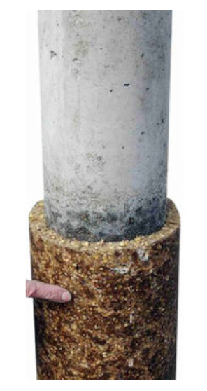 | 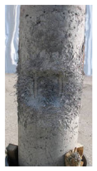 | 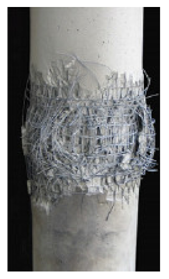 | 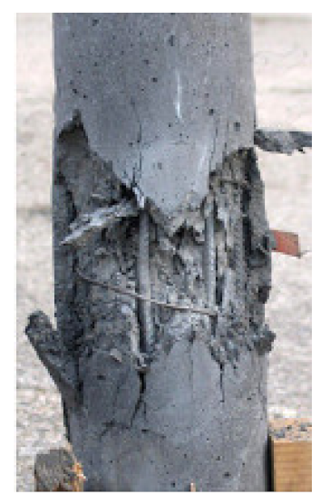 |
| Residual load capacity | 5.5% | 68.6% | 69.6% | 49.3 (coarse)– 65.9 (fine) % | - |
| Author | Year | Structural Element | Software |
|---|---|---|---|
| Ray et al. [46] | 2003 | Bridge deck and column | ConWep, BlastX, SHAMRC |
| Marchand et al. [36] | 2004 | Bridge columns | BlastX, ConWep, SPAn32 |
| Winget et al. [2] | 2005 | Bridge concrete girders, deck, columns | BlastX, SPAn32, Nonlin |
| Rutner et al. [47] | 2006 | Steel and composite bridge columns | MSC.Dytran |
| Wu et al. [48] | 2009 | RC and composite building columns | LS-Dyna |
| Hao et al. [49] | 2010 | RC building columns | CARLER |
| Elsanadedy et al. [50] | 2011 | RC building columns + CFRP | LS-Dyna |
| Williams et al. [51] | 2011 | RC bridge columns | LS-Dyna |
| Williams et al. [52] | 2011 | RC bridge columns | LS-Dyna |
| Crawford [10] | 2013 | RC building columns + FRP + SJ | LS-Dyna |
| Magali et al. [53] | 2013 | RC building columns | Abaqus |
| Eisa [54] | 2014 | RC building columns | Abaqus |
| Abladey and Braimah [55] | 2014 | RC building columns | Autodyn |
| Li and Hao [56] | 2014 | RC column | LS-Dyna |
| Shi and Stewart [57] | 2015 | RC building column | LS-Dyna |
| Liu et al. [58] | 2015 | RC bridge pier-bent model | LS-Dyna, ConWep |
| Cui et al. [59] | 2015 | RC column | LS-Dyna |
| Zhang et al. [12] | 2015 | CFST building columns | LS-Dyna |
| Codina et al. [14] | 2016 | RC building column | Autodyn |
| Zhang et al. [21] | 2016 | CFDST columns | LS-Dyna |
| Arowojolu et al. [60] | 2017 | RC bridge column | LS-Dyna |
| Eamon and Aslendi [61] | 2017 | RC bridge columns + SFRP | LS-Dyna |
| Kravchenko et al. [62] | 2017 | RC building columns | LS-Dyna |
| Kyei and Braimah [63] | 2017 | RC building columns | LS-Dyna |
| Yuan et al. [23] | 2017 | RC bridge columns | LS-Dyna |
| Abedini et al. [64] | 2018 | RC building columns | LS-Dyna |
| Li et al. [65] | 2018 | CFDST bridge columns | LS-Dyna |
| Liu et al. [66] | 2018 | RC bridge piers | LS-Dyna, ConWep |
| Li et al. [67] | 2019 | CFDST bridge columns | LS-Dyna |
| Liu et al. [68] | 2019 | RC building columns | Autodyn, LS-Dyna |
| Liu et al. [69] | 2019 | RC bridge column + CFRP | LS-Dyna |
| Thai et al. [70] | 2019 | RC column + SJ | LS-Dyna |
| Abedini et al. [71] | 2019 | RC column | LS-Dyna |
| Dua et al. [72] | 2019 | RC columns | LS-Dyna |
| Dua et al. [28] | 2020 | RC columns | LS-Dyna |
| Li et al. [73] | 2020 | CFDST columns | LS-Dyna |
| Rajkumar et al. [74] | 2020 | RC columns | LS-Dyna |
| Vavilala et al. [75] | 2020 | RC building columns + polymeric foam | Abaqus |
| Zhang et al. [76] | 2020 | Segmental CFST column | LS-Dyna |
| Yuan et al. [77] | 2020 | RC column | LS-Dyna |
| Yan et al. [78] | 2020 | RC columns + CFRP | LS-Dyna |
| Hu et al. [79] | 2021 | RC column + CFRP | LS-Dyna |
| Level of Damage [49] | Damage Limit States [57] | |
|---|---|---|
| Low damage | 0–0.2 | Low damage |
| Medium damage | 0.2–0.5 | Repairable damage |
| High damage | 0.5–0.8 | Repairable damage |
| Collapse | 0.8–1.0 | Collapse |
| Parameters (a) | Autodyn (Default) [86] (b) | Tu and Lu [93] (c) | Codina et al. [14] (d) |
|---|---|---|---|
| B | 1.6 | 0.7 | 0.35 |
| M | 0.61 | 0.8 | 0.55 |
| RHT damage model | |||
| D1 | 0.04 | 0.015 | 0..8 |
| D2 | 1 | 1 | 1 |
| 0.01 | 8.00 × 10⁻⁴ | 0.03 | |
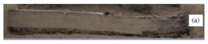 |  | 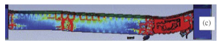 | 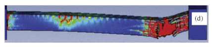 |
Publisher’s Note: MDPI stays neutral with regard to jurisdictional claims in published maps and institutional affiliations. |
© 2021 by the authors. Licensee MDPI, Basel, Switzerland. This article is an open access article distributed under the terms and conditions of the Creative Commons Attribution (CC BY) license (https://creativecommons.org/licenses/by/4.0/).
Share and Cite
Lukić, S.; Draganić, H. Blast Loaded Columns—State of the Art Review. Appl. Sci. 2021, 11, 7980. https://doi.org/10.3390/app11177980
Lukić S, Draganić H. Blast Loaded Columns—State of the Art Review. Applied Sciences. 2021; 11(17):7980. https://doi.org/10.3390/app11177980
Chicago/Turabian StyleLukić, Sanja, and Hrvoje Draganić. 2021. "Blast Loaded Columns—State of the Art Review" Applied Sciences 11, no. 17: 7980. https://doi.org/10.3390/app11177980
APA StyleLukić, S., & Draganić, H. (2021). Blast Loaded Columns—State of the Art Review. Applied Sciences, 11(17), 7980. https://doi.org/10.3390/app11177980