Article

Analytical Model Formulation of Steel Plate Reinforced Concrete Walls against Hard Projectile Impact

1
School of Mechanical Engineering, Nanjing University of Science and Technology, Nanjing 210094, China
2
National Key Laboratory of Transient Physics, Nanjing University of Science and Technology, Nanjing 210094, China
*
Author to whom correspondence should be addressed.
Appl. Sci. 2022, 12(1), 518; https://doi.org/10.3390/app12010518
Submission received: 6 December 2021 / Revised: 30 December 2021 / Accepted: 1 January 2022 / Published: 5 January 2022
(This article belongs to the Special Issue Blast and Impact Engineering on Structures and Materials)

Abstract

:
Steel plate reinforced concrete (SC) walls can effectively resist projectile impact by preventing the rear concrete fragments flying away, thus attracting much attention in defence technology. This work numerically and analytically investigated the hard projectile perforation of steel plate reinforced concrete walls. Impact resistance theories, including cavity expansion analysis as well as the petaling theory of thin steel plates were used to describe the cratering, tunneling and plugging phases of SC walls perforation. Numerical modeling of SC walls perforation was performed to estimate projectile residual velocity and target destructive form, which were validated against the test results. An analytical model for SC wall perforation was established to describe the penetration resistance featuring five stages, i.e., cratering, tunneling and plugging, petaling with plugging and solely petaling. Analytical model predictions matched numerical results well with respect to projectile deceleration evolution as well as residual velocity. From a structural absorbed energy perspective, the effect of front concrete panel and rear steel plate thickness combinations was also studied and analyzed. Finally, equivalent concrete slab thickness was derived with respect to the ballistic limit of SC walls, which may be helpful in the design of a protective strategy.

1. Introduction

Characterized with easy shaping, efficient fabrication and construction, concrete material structures are widely used for most civilian and military infrastructure, e.g., nuclear power plants, liquefied natural gas storage tanks and civil air defence, which are designed to withstand extreme loading, such as aircraft engine impact as well as internal and external missile impact [1,2,3]. Under projectile penetration, attaching a relative thin steel plate onto the concrete wall rear (protected) face would better protect the inner inhabitants and vulnerable instruments by preventing rear face ejected fragmentation, which might occur even if the concrete panel is not breached. In practice, steel plate reinforced concrete (SC) walls have been effectively used as primary and secondary shelters in protective structures. It is important to develop a simple but robust analytical model for projectile perforation on SC walls.
SC walls have superior performance in terms of resisting impact loading, since the rear steel plate induces a considerable effect on limiting crater development and preventing the pulverized pieces from flying away. Concerning the impact resistance of the SC walls, experimental studies have compared and analyzed projectile impact tests on concrete slabs with and without the rear steel plate. Remennikov et al. [4,5] investigated the static and impact performance of SC walls in which no shear connectors were utilized to connect the steel faceplates and the concrete core. Owing to the specially designed connection details, the tested panels exhibited tensile membrane resistance at large deformations. Armour-piercing projectiles impacting high-strength concrete backed by armoured steel were studied by Feng et al. [6], showing spaced composite targets had larger residual penetration depth than segmented ones. Kojima [7] concluded that the rear attached steel plate has little effect on enhancing the impact resistance of SC walls, while it can efficiently restrain scabbing and spalling fragments. Aiming at identifying the influence of the steel plate on local damage of SC walls, Tsubota et al. [8] performed a series of impact tests in which the steel plate was placed on the rear, front and both faces of a concrete panel, respectively. The rear steel plate attached to reinforced concrete (RC) plate could prevent local damage caused by perforation, while the front steel plate attached to the impacted face had a relatively slight effect. Abdel-Kader and Fouda [9] showed that the steel plate placed on the rear face had better impact performance than the front one, which further validated the above conclusion. Hashimoto et al. [10] also showed that a thicker steel plate would result in less local damage under low-velocity impact. Mizuno et al. [11] found that SC panels have better impact resistant performance than RC panels, which enabled reduction of panel thickness by almost 30%.
Bruhl et al. [12] developed an analytical and empirical model of SC walls under rigid projectile impact and proposed a three-step method for designing SC walls against missile impact which can be used to evaluate the ballistic limit of SC walls. For rigid projectile perforation, Grisaro and Dancygier [13] investigated the thickness of the SC composite barrier with respect to energy absorption. Wu et al. [14] performed projectile perforation tests on monolithic and segmented RC panels with a rear steel plate. The ballistic performances of layered RC and SC targets were analyzed quantitatively, which further validated the equivalent approach in Ref. [13]. To assess the core concrete thickness and steel ratios effect on failure modes, Lee and Kim [15] numerically evaluated the impact resistance of SC and RC panels via a LS-DYNA solver, suggesting SC walls can better resist impacting loads than RC panels.
Although extensive studies on SC structures have been conducted both experimentally and numerically, analytical models of hard projectile perforation on SC walls need to be further explored. Cavity expansion analysis and petaling theory were combined to describe the cratering, tunneling and plugging phases of SC wall perforation. Front concrete wall perforation resistance was analyzed by perforation modeling via non-linear transient dynamic solver LS-DYNA. The thin plate petaling theory was utilized to analyze the process of rear face plate damage by projectile impact. With the same ballistic limit, a semiemperical analytical model, converting SC walls to equivalent thickness concrete panels, was developed and validated. This work may shed some light on SC wall ballistic performance related to protective structure design.

2. Impact Resistance Theories

Since the composite structure of SC walls consists of a front concrete plate attached to a rear steel plate, the ballistic performance of SC walls should be roughly separated into three parts: penetration of the front concrete, perforation of the steel plate and interaction with both concrete and steel. When a projectile perforates a concrete panel with a certain thickness it goes through three response stages: front crater scabbing, stable tunneling, and rear crater plugging (spalling) [16]. The impact perforation response of thin steel plates has been successfully analyzed by the petaling theory proposed by Wierzbicki [17].
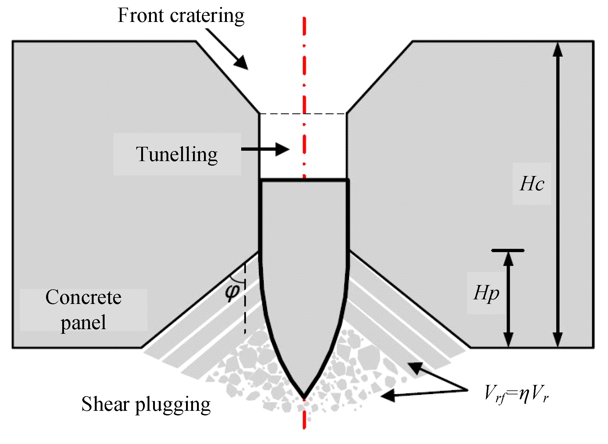
This work developed a semiemperical analytical model of projectile penetration of steel plate reinforced concrete walls based on five penetration stages, as plotted in Figure 1. Stage 1 is projectile cratering on the front concrete impact face. Stage 2 represents stable tunneling inside the concrete block. Afterwards, rear face plugging occurs in Stage 3 until the projectile starts to hit the rear steel plate. Stage 4 occurs when the projectile interacts with the steel plate and fragments the concrete rear face. Finally, the projectile head has interaction only the steel plate in stage 5. Hence, the penetration resistance consists of concrete resistance and steel plate resistance. Classical resistance equations are introduced below.

2.1. Cavity Expansion Analysis for Concrete

Introduced by Bishop et al. [18], cavity expansion analysis was applied to solve the governing equations of the spherical cavity or cylindrical cavity expansion process in an elasto-plastic incompressible medium. Then Forrestal and Luk et al. [19] extended this to compressible material penetration problems. This classical model has been successfully applied to metal and concrete material penetration analyses.
Projectile penetration inside a solid medium can be regarded as a spherically symmetric cavity expansion process. Embedded in an infinite and isotropic medium, the zero initial radius cavity expands at a constant velocity. Due to the instantaneous rise of dynamic pressure, spherical stress waves are generated to form different response regions corresponding to the concrete constitutive law. According to continuum mechanics, equations of mass conservation and momentum conservation [8] in Euler coordinate for compressible spherical cavity expansion analysis at time t are:
div   σ = ρ a
ρ t + div ( ρ v ) = 0
where σ is the stress tensor, a is acceleration, and v is velocity. In a spherical coordinate system, the governing equations [9] can be expressed as:
σ r r + 2 ( σ r σ θ ) r = ρ ( v t + v v r )
ρ ( v r + 2 v r ) = ( ρ t + v ρ r )
where r is the radial coordinate, and σ r and σ θ are radial and circumferential Cauchy stress.
With the corresponding constitutive law for concrete materials, attempts have been made to numerically solve the governing equations with the Runge-Kutta method [20]. The normal stress σ n , referred as penetration resistance, acting on the projectile nose is usually expressed as:
σ n = ρ v 2 + R
where ρ v 2 and R represent the inertial dynamic resistance and static resistance. Forrestal and his coworkers [21,22,23] deemed the target strength parameter as R = S f c where S is a dimensionless constant and f c is the unconfined compressive strength of concrete. After validation with extensive penetration data [21,22,24,25,26], the semiempericial penetration model gives:
S = 82.6 ( f c / 10 6 ) 0.544
Recently, researchers have pointed out that the above penetration resistance equation only applies to medium caliber projectile cases (shank diameter ranging from 12.9 mm to 30.5 mm) [27]. To avoid the concrete size effect in penetration, this work focuses on a 1-inch (25.4 mm) diameter projectile meeting the application range.

2.2. Perforation with Shear Plugging

After cratering and tunneling, the interaction between the projectile and shear plugging fragments can be treated as a collision problem. In Figure 2, the fragments with velocity Vrf are pushed away by the projectile, whereby the shear plugging zone is a frustum-of-cone with cone slope angle φ . The projectile residual velocity Vr can be derived from:
1 2 m V r 0 2 = 1 2 m V r 2 + 1 2 ρ c Ω V r f 2
where Vr0 is the initial projectile velocity of the plugging stage, fragments velocity can be estimated by V rf = η V r and η = 0.2 according to [14], the cone slope angle φ = 62.5 ° is given by Peng et al. [28], and Ω is the volume of the ejected frustum-of-cone fragment, which can be expressed as:
Ω = π 12 H p ( 4 tan 2 φ H p 2 + 6 d p tan φ H p + 3 d p )
where H p is the shear plugging thickness, and d p is the projectile diameter.

2.3. Thin Plate Petaling

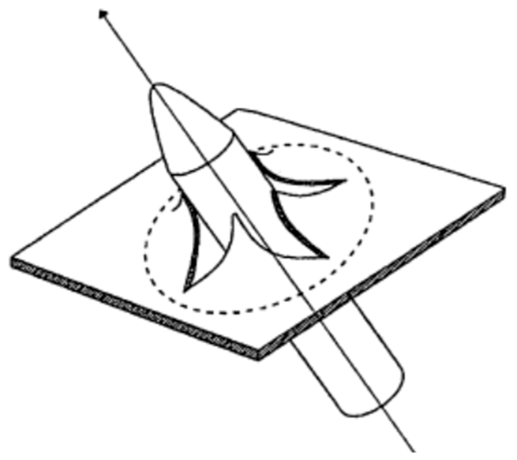
Characterized by multiple symmetric petals forming, petaling damage is a common failure mode of thin metal plates when subjected to localized high intensity loadings, e.g., projectile perforation as shown in Figure 3. The shock wave pressure and the cavity tear the thin shell to generate a much larger radius. The tearing fracture energy is related to the bending energy through the petal local radial curvature and the circumferential curvature. From an energy perspective, the energy consumption of projectile perforation on the thin metal plate results from petaling energy and plastic deformation:
Ec = WL + WG
where WL denotes the petaling energy, and WG represents the plastic energy during plate deformation.
According to Wierzbicki [17], the petaling energy due to projectile perforation can be expressed as:
W L = 3.37 σ 0   δ ¯ 0.2 h t 1.6 d p 1.4
where δ ¯ = δ t / h t , δ t = R t / ( 3 σ u ) , R t denotes the impact toughness, δ t is the crack tip opening displacement parameter (CTOD), h t is the plate thickness, σ u is the ultimate strength and σ 0 is the nominal strength.
Landkof and Goldsmith [29] measured the plastic deformation energy according to the ballistic tests, hence thin plate perforation energy consumption Ec can be written in the dimensionless form:
E c σ 0 d p 3 = 3.37 δ ¯ 0.2 ( h t d p ) 1.6 + 2.8 ( h t d p ) 1.7

3. Perforation Model Validation

Recently, Wu et al. [14] conducted penetration experiments to study the ballistic performance of reinforced concrete panels with a rear steel plate which provided valuable data for SC wall perforation analyses. For the sake of analytical model formulation, hypotheses needed to be verified via extensive test data both from experiments and simulations. This section aims to develop the FE numerical model for SC walls perforation which was validated against test data.

3.1. Perforation Test and FE Model

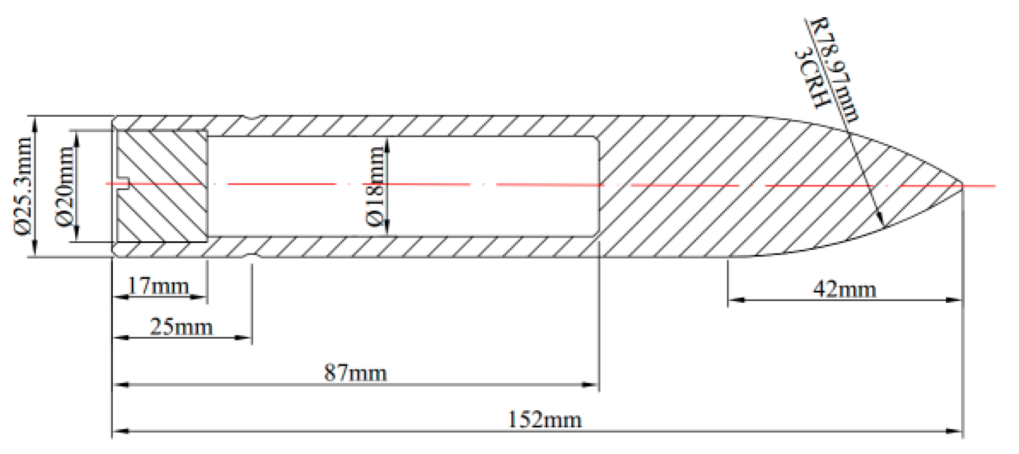
With an ogival-shaped nose, hard projectiles were used for penetration tests in which no apparent erosion occurs. The total projectile mass was 428 g, the shank diameter was 25.3 mm and the caliber-radius-head (CRH) of the ogival nose was 3.0, as shown in Figure 4.
Simulations of the SC walls perforation tests were conducted with 200-mm thick concrete panels. Figure 5 depicts the target dimension together with its reinforced mesh. The projectile impact location point is denoted by ‘×’. For the investigated concrete, the unconfined compressive strength of cylinder sample ( f c ) was 41 MPa.
For the numerical study, LS-DYNA, the extensively applied explicit solver, was adopted for impact simulations. Since the projectile material was of high strength and great hardness, the projectile was modeled as MAT_RIGID in the simulation. Successfully applied for concrete penetration simulations [30], the Holmquist-Johnson-Cook (HJC) model [31] was chosen to model the concrete material. Originally presented by Holmquist, Johnson and Cook [32], the HJC concrete model was developed for the purpose of impact computations where the material experiences large strains, high strain rates and high pressures. Coupled with isotropic damage, the HJC concrete model is an elastic-viscoplastic model [33] where the deviatoric response is determined by the following constitutive law:
σ Y * = [ A ( 1 D ) + B p * N ] [ 1 + C ln ε * ]
in which σ Y * = σ Y / f c is the normalized equivalent stress, and p * = p / f c is the normalized pressure.
The equation of state in HJC is characterized by three stages: plate elastic (for p < p c ) p = K μ ; pore collapse (for p c p p 1 ) p = p c + ( p 1 p c ) ( μ μ 1 ) / ( μ 1 μ c ) ; compaction (for p > p 1 ) p = k 1 μ ¯ + k 2 μ ¯ 2 + k 3 μ ¯ 3 with μ ¯ = ( μ μ 1 ) / ( 1 + μ 1 ) ; k 1 , k 2 , and k 3 are constants.
The HJC model includes a scalar damage formulation, where the damage evolution is accumulated from both the equivalent plastic strain increment Δ ε eq p and the equivalent plastic volumetric strain increment Δ μ eq p . The damage evolution is expressed as:
Δ D = Δ ε eq p + Δ μ eq p ε p f + μ p f
where, ε p f + μ p f = D 1 ( p * + T * ) D 2 , ε p f and μ p f are plastic strain and plastic volumetric strain corresponding to fracture, T * is the normalized tensile strength, and D 1 and D 2 are damage constants.
The steel plate was modeled by the Johnson-Cook (JC) model [34] for its wide adoption in the metal impact engineering domain. JC is a strain rate and temperature-dependent (adiabatic assumption) visco-plastic material model [35,36]. This model is suitable for problems in which strain rates vary over a large range. The JC model expresses the flow stress with the form:
σ Y = [ A + B ε p N ] [ 1 + C ln ε * ]
where σ Y is the effective stress, ε p is the effective plastic strain, ε * is the normalized effective plastic strain rate (typically normalized to a strain rate of 1.0 s−1), N is the work hardening exponent, and A, B, C are constants determined by calibration.
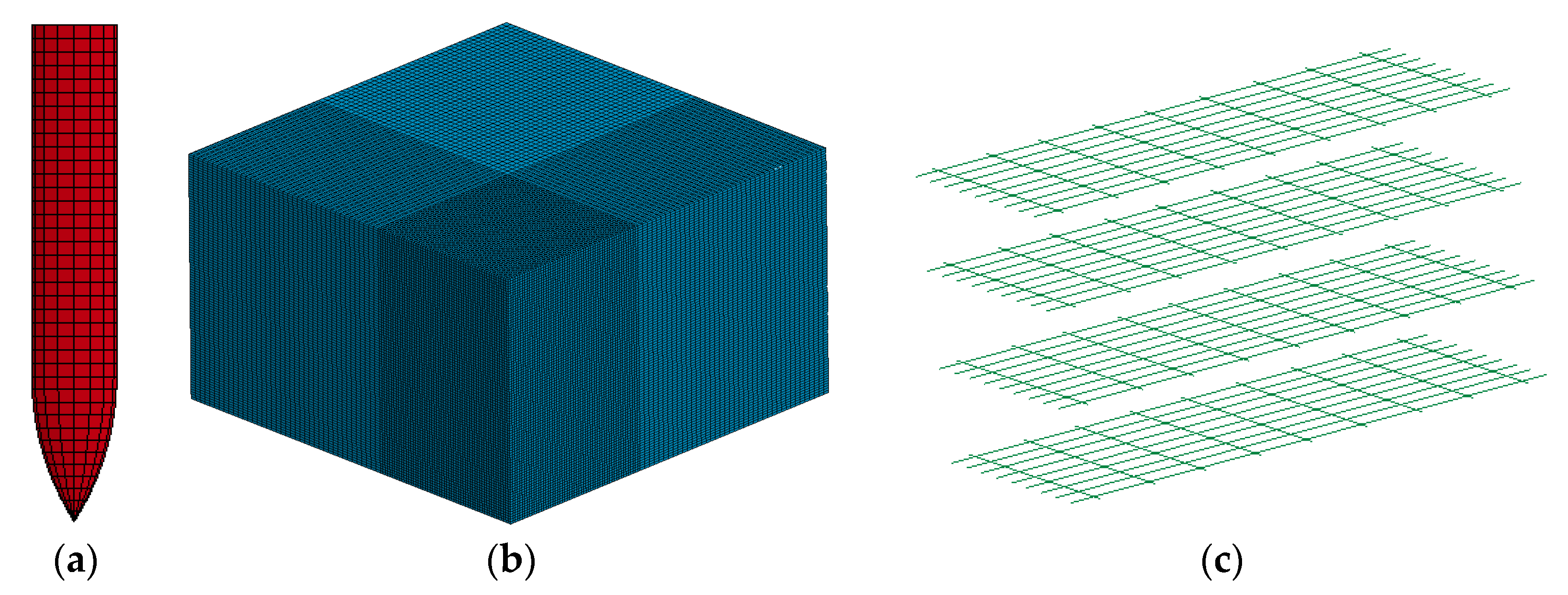
With reference to [37], the steel rebar was modeled using MAT_PLASTIC_KINEMATIC. For the concrete HJC model and the steel 1006 JC model, the main parameters are listed in Table 1 and Table 2 where those model parameters have been validated against available penetration tests [38,39]. In the test set up, all the top and bottom surfaces of the target were constrained. Element sizes were strictly controlled to guarantee that the steel mesh nodes coincide with concrete element nodes. Figure 6 shows the finite element model developed for SC wall penetration. Table 3 lists the element numbers of projectile, concrete panel, steel mesh as well as steel plate. The refined concrete mesh of the impact area was 3 mm, with 6 mm mesh for the outer region, which have been proven as converged meshes for penetration simulation [40]. The projectile was meshed with 1 to 3 mm size hexahedrons. The meshing sizes of the reinforced rebars were 3 mm and 6 mm. The rear steel plate was modeled with 1 mm × 1 mm × 1 mm for the center area and 1 mm × 2 mm × 2 mm for the outer region.

3.2. Numerical Results, Validation and Discussion

In this work, five penetration simulations with different striking velocities ( V s ), were carried out to validate the numerical model. After simulation, numerical predictions of projectile residual velocities ( V r , n ) were compared against test data ( V r , e ) as shown in Figure 7a. As listed in Table 4, the numerical predictions agreed well with the test data. It is also suggested that with a 436 m/s striking velocity, the projectile perforated the SC wall with quite a small residual velocity which was overestimated by the numerical model. Figure 7b shows the projectile velocity history during perforation, implying that it takes less time to perforate the SC wall at higher striking velocity.
Figure 8 compares the post-test target and numerical results from different views. Figure 8a shows the constraints of the target, which was fixed in the steel frame. The actual destructive forms of the rear target are also shown. A three-stage perforation model [16,40] consisting of front impact crater, ballistic tunnel, and a nearly frustum-of-cone shaped rear crater is shown in Figure 8b. In Figure 8c, the steel plate deformation is shown and it was notable that the neighboring area of the plate around the projectile suffers severe deformation. From a cross-section view of the SC walls, Figure 8d illustrates the damage mode of the target in which the foregoing three-stage thick plate model was numerically verified. From the validation results in terms of damage mode and residual velocity, the numerical predictions match well with SC wall perforation tests.

4. Numerical Study of SC Walls Perforation

This section describes the extensive numerical investigations on SC wall perforations with different concrete panels and steel plates. SC walls with different front concrete panel and rear steel plate thickness combinations are investigated in this section considering protective structure analysis.

4.1. Model Setting

The previously described ogival nose projectile was used as the penetrator. With an 800 mm length and width, the investigated concrete panels were attached with 3 mm to 11 mm thicknesses of the rear steel plate. With the same cross section, the concrete panel thicknesses were selected as 150 mm, 200 mm and 250 mm, respectively. For SC walls with 200-mm thick concrete panel, the striking velocities of the projectile were set at 550, 600, 650, 700 and 800 m/s. Furthermore, a striking velocity of 600 m/s was set for perforation simulations with 150 mm and 250 mm thick concrete panels.
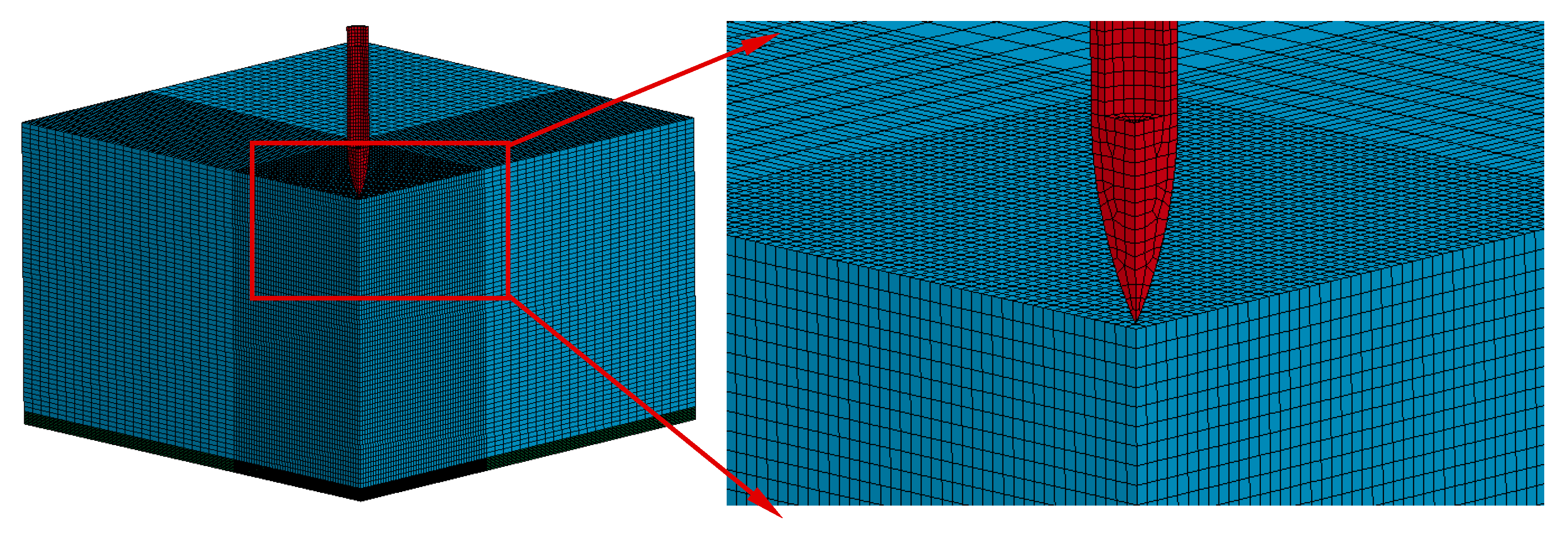
For the sake of computational cost, the SC walls perforation models were developed as quarterly symmetric bodies with symmetric boundaries. Figure 9 shows the FE model in which the grids near the impact region were refined. For the 1/4 model of SC walls with a combination of 11 mm thickness steel plate and 250-mm thick concrete panel, the element numbers for the three parts are given in Table 5. These material models and their parameters are the same as in the validation model. An eroding algorithm was applied to all the interactions between the contact components.

4.2. Results Discussion of SC Walls Perforation

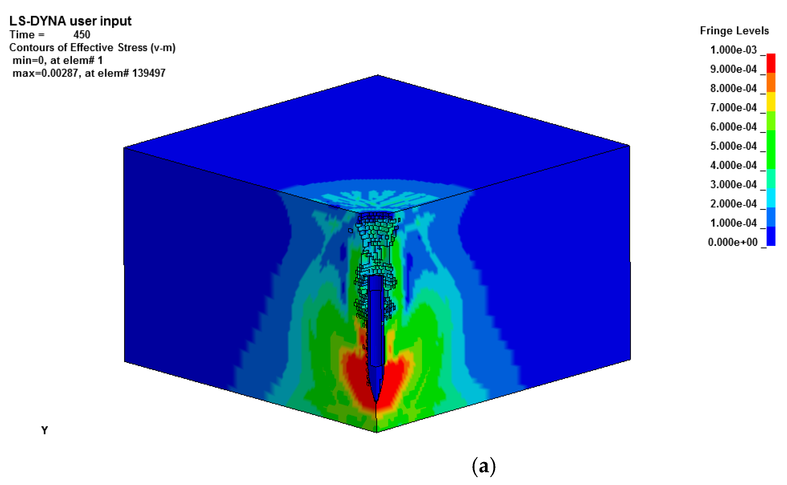
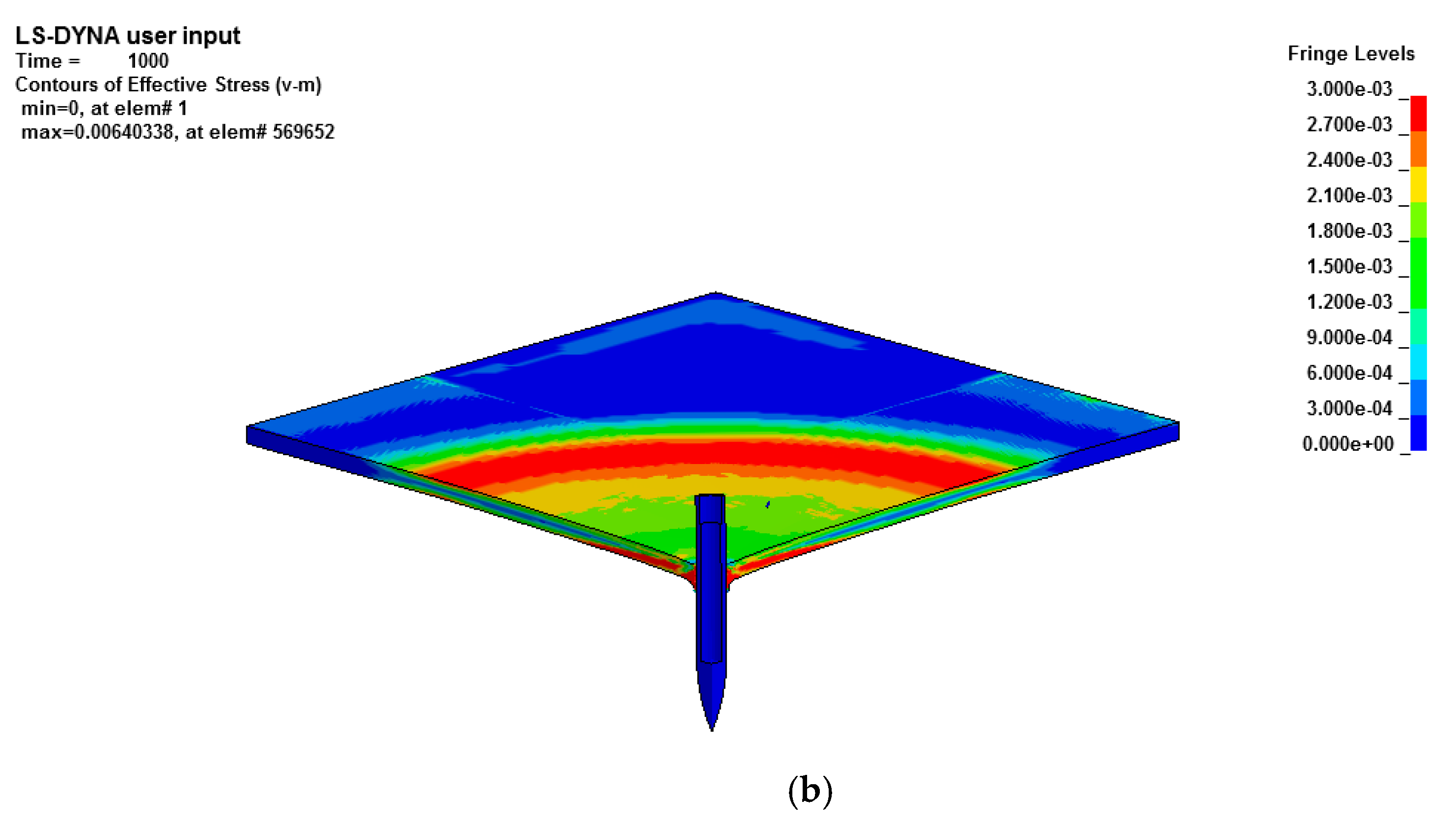
Seven kinds of thickness combinations of concrete panel and steel plate were used for the SC wall perforation analysis. Figure 10 shows the numerical results for an SC wall with a 250 mm thick concrete panel and an 11 mm thick steel plate. The projectile striking velocity was 600 m/s and the SC wall was perforated as expected. The destructive area of concrete rear surface was larger than its front impact surface due to conical plugging occurring in the back area. In Figure 10b, the von-Mises stress distribution contour exhibits a circular character.
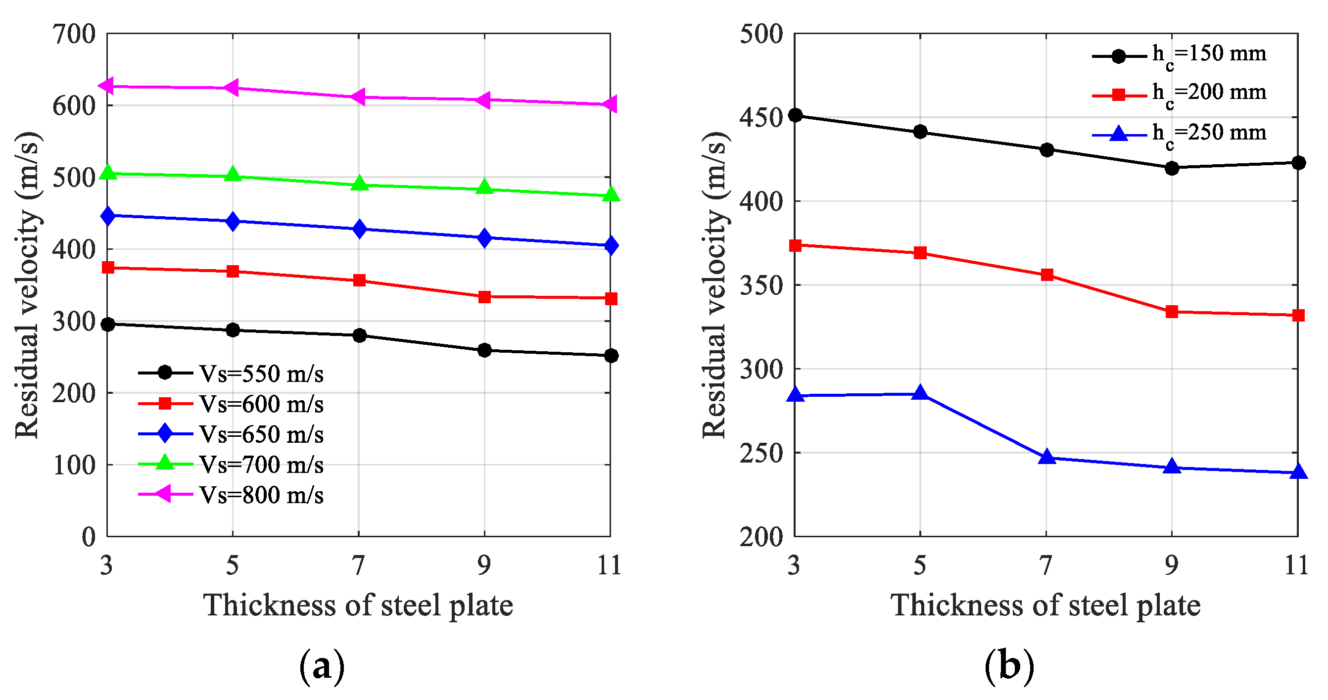
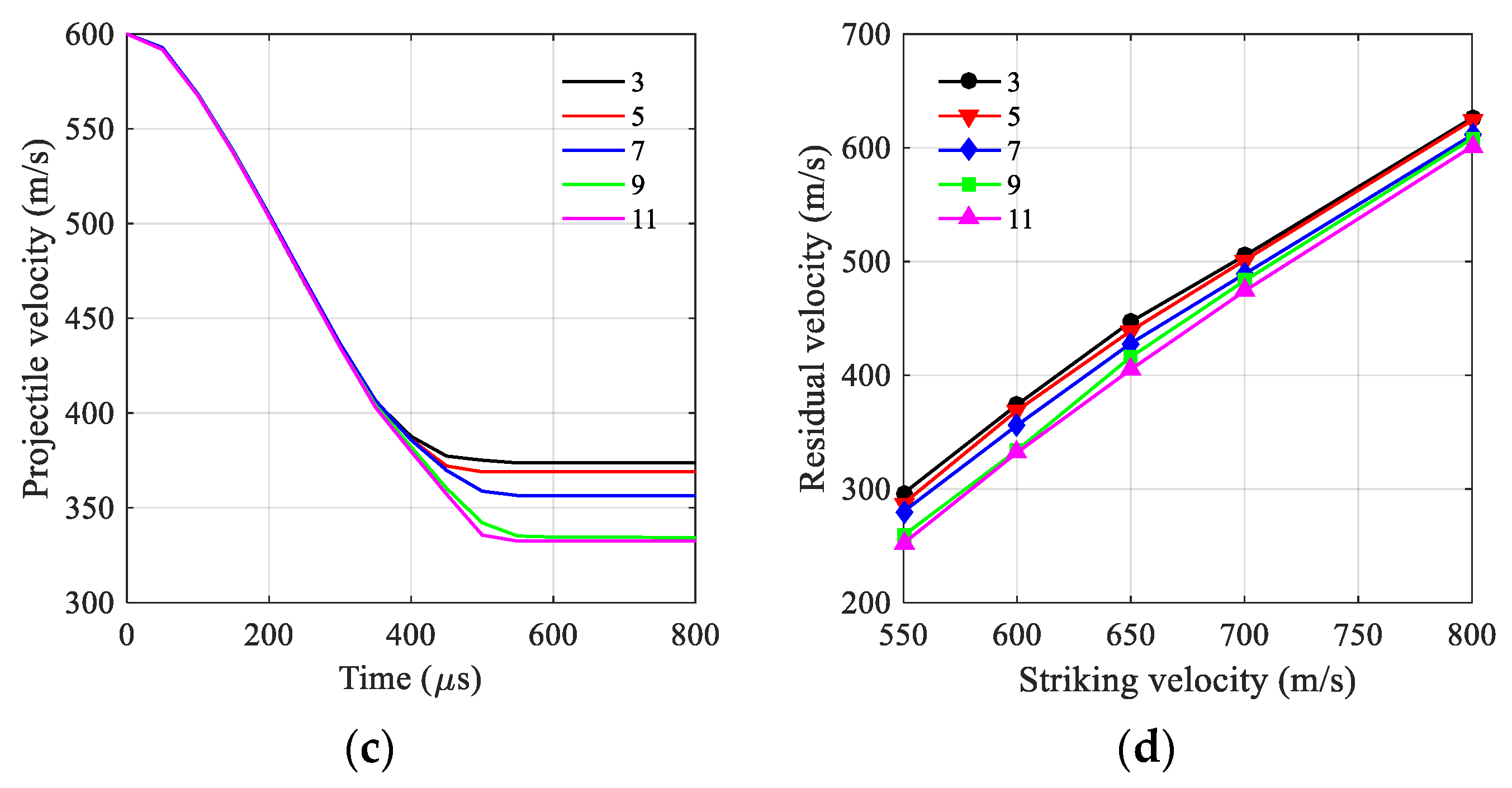
To examine the penetration responses of SC walls under various striking velocities, a 200-mm thick concrete panel supported by rear steel plates with different thickness was numerically studied. Backing steel plates with different thickness were assumed to have various effects on the penetration resistance. Figure 11a illustrates that projectile residual velocity decreased with increasing thickness of the rear steel plate when the striking velocity was close to the ballistic limit [4]. Figure 11b shows the residual velocities for 150, 200 and 250 mm thick concrete panels subjected to a 600 m/s striking velocity impact. With the residual velocity increasing, the curve of velocity over time shows a slightly oscillating character. Under 600 m/s striking velocity impact, the projectile velocity history during SC wall perforation with a 200-mm thick concrete panel is shown in Figure 11c. The early penetration responses were almost the same, due to the fact that the backing steel plate had no influence on impact resistance of the front concrete target. Concerning the later perforation process, results imply that the rear steel plate has a significant effect on penetration resistance. Figure 11d shows the striking velocities and the residual velocities after perforation of SC walls with 200 mm thick concrete panels. With increasing striking velocity, it seems that the rear steel plate had a less pronounced effect on penetration resistance and thus the residual velocities tend to converge.

4.3. Free Surface Boundary Effect

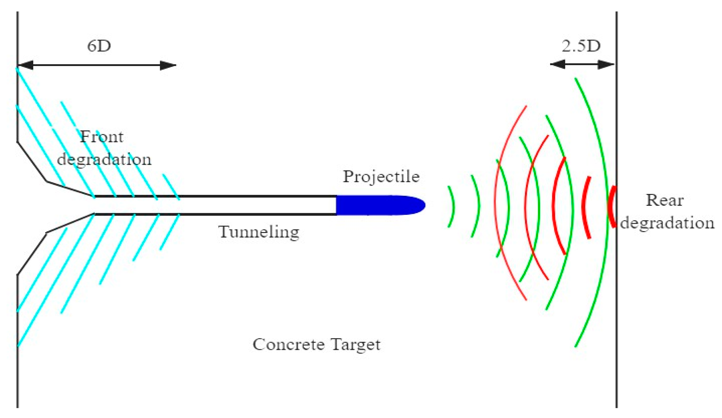
Although cavity expansion analysis was successfully applied to projectile deep penetration in concrete, the typical penetration resistance equation proposed by Forrestal et al. [23] was not suitable for a projectile perforation scenario with a concrete panel of limited thickness. The front and back free surfaces might degrade the material strength thus reducing the penetration resistance during cratering and shear plugging, as shown in Figure 12. Therefore, the penetration resistance prior to shear plugging should be revised in the case of a concrete panel with limited thickness.
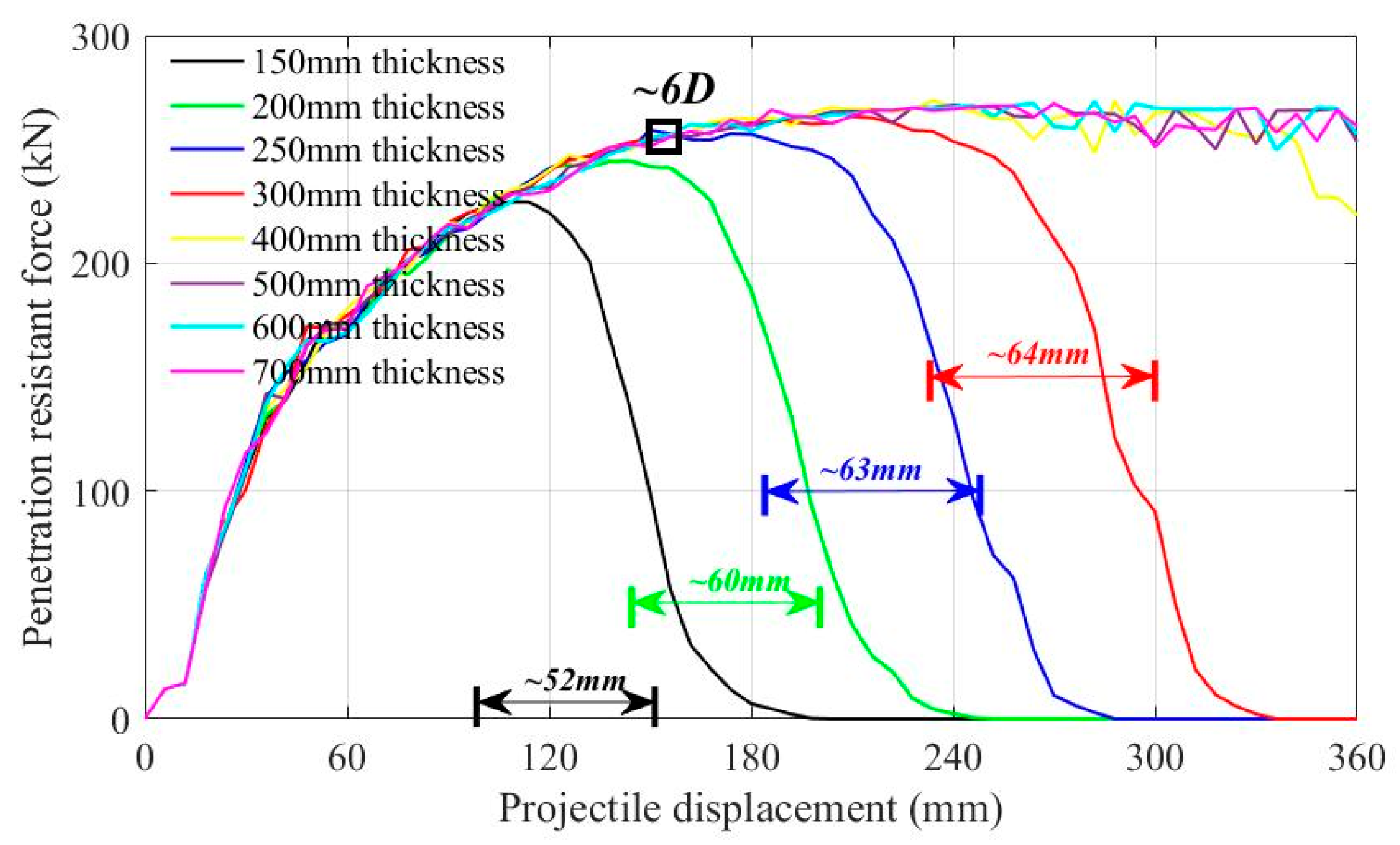
To develop a penetration resistance equation with respect to penetration velocity, numerical simulations with constant projectile velocity were performed to derive the penetration resistance acting on the projectile nose. Since the front and rear free surface might negatively affect the penetration resistance, concrete panels with thicknesses of 150, 200, 250, 300, 400, 500, 600 and 700 mm were selected for simulation. According to the results plotted in Figure 13, it is interesting that penetration resistant force increased to a plateau. This can be explained by the fact that the front surface degraded the penetration resistance until reaching about 6dp. The rear free surface effect was estimated by penetration simulation of panels with 250 mm and 300 mm thickness. Both had a stable plateau during tunneling and started to drop at a position about 68 mm to 70 mm away from the rear surface. The shear plugging height was about 2.5dp which matches well with experimental data in Ref. [34]. For 150 mm and 200 mm thickness concrete panels, both the front and rear free surface affected the penetration resistance, implying no stable tunneling.

5. Theoretical Analyses of Hard Projectile Perforation on SC Walls

According to the foregoing spherical cavity expansion theory, as well as thin steel plate petaling destruction, a semiempirical analytical model was proposed derived from numerical results. The SC wall composite target was composed of concrete and steel; therefore, the penetration resistance acting on the projectile nose was attributed to the concrete and steel plates. The concrete resistance at different penetration stages is related to cavity expansion analysis. The thin steel plate destruction mode due to perforation is generally petaling, hence the penetration resistance may be derived with a petaling model.

5.1. Penetration Resistance Force

The typical ogival-shaped nose projectile is illustrated in Figure 14, where the projectile nose length and shank diameter are denoted as h and dp. Assuming a projectile with a striking velocity V, the normal expansion velocity perpendicular to the nose curve is v = V s i n θ . Take the micro segment length dx to study the stress distribution over the infinite projectile nose surface ds. The resistant force d f can be treated as the normal stress σ n projection along the projectile axial direction:
d f = σ n s i n θ d s
Integrating the normal stress σ n over the projectile nose to achieve the axial penetration resistant force:
F =   σ n s i n θ d s
d s = 2 π | y | 1 + | k | d x
For thick concrete targets, the Forrestal model [41] derived from the empirical formula S = 82.6 ( f c / 10 6 ) 0.544 , was applied to describe the static penetration resistance. Hence, the normal resistant stress can be expressed as: σ n = S f c + ρ v 2 , where f c is the unconfined cylinder compressive strength of concrete and ρ is the density of concrete target.
When the ratio of the metal plate thickness h t and the shank diameter dp is no larger than 0.5, petaling is generally the damage form of the thin metal target subjected to vertical impact. During the rear steel plate petaling process, the perforation energy E c in Equation (11) can be regarded as mean resistant force accumulation over the deformation. Therefore, the mean resistant force can be estimated as F m e a n = E c / d , whereas d is the actual petaling displacement.

5.2. Stages of SC Walls Perforation

Based on the SC wall penetration resistance mechanism, a five-stage semiempirical analytical model was developed, i.e., projectile nose part penetration in concrete (cratering), stable penetration (tunneling), shear plugging, plate petaling with concrete plugging and plate petaling only, as depicted in Figure 1.
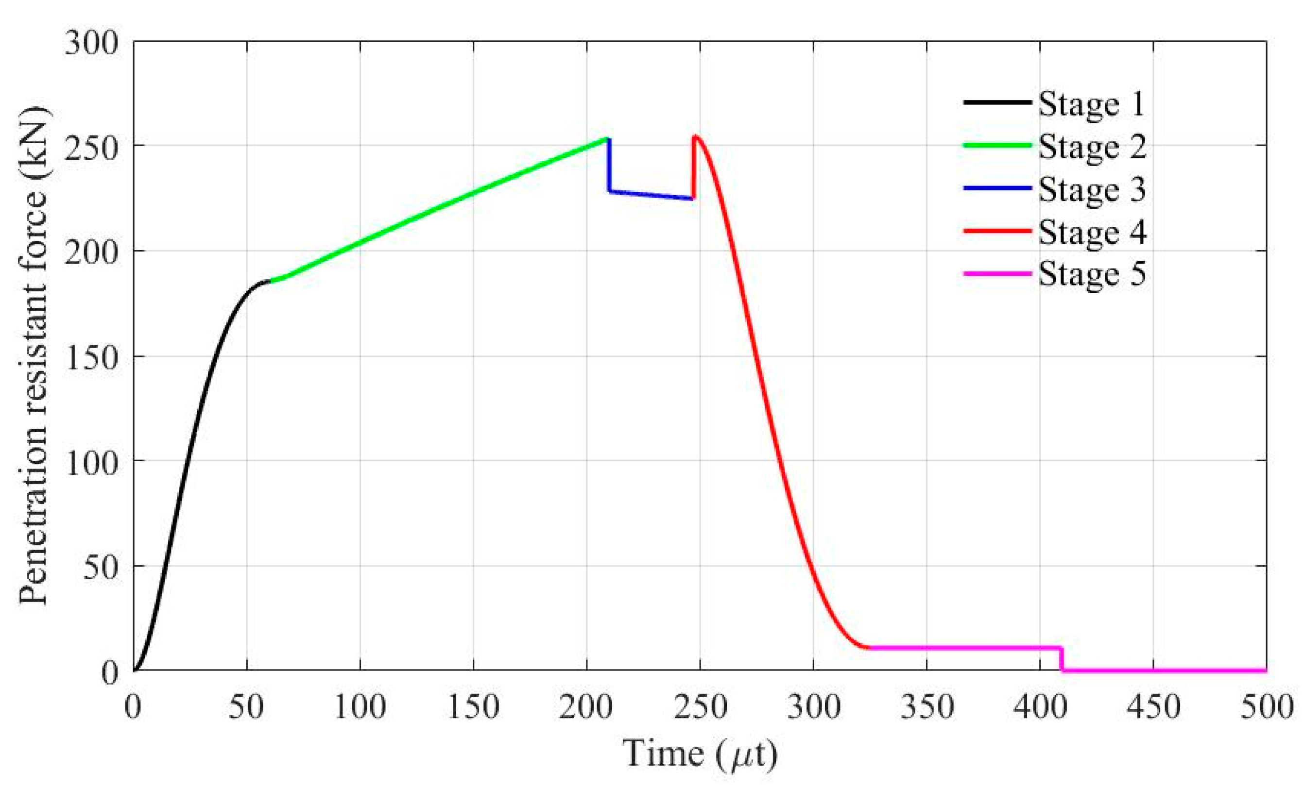
For stage 1 and 2, the projectile penetrates the front concrete panel with different contact areas. Hence, a deep penetration model [32,33] is utilized to analyze the first and second perforation stages. For penetration in the concrete panel, the normal stress σ n , c acting on the projectile nose can be expressed as σ n , c = S f c + ρ v 2 where f c = 41   MPa , ρ = 2240   kg / m 3 . The static resistance term in the normal direction S f c = 82.6 × ( f c / 10 6 ) 0.544 × f c = 449.17   MPa and the dynamic term ρ v 2 change with actual projectile velocity.
During stage 3, the projectile passes through the concrete fragments until it hits the rear steel plate. For thicker rear plates, the pulverized concrete pieces in the rear crater have more support and provide more penetration resistance to the projectile. Related to its thickness, a certain deformation happens to the rear steel plate. According to previous literature [14,28,42,43], it is assumed that the rear crater depth of the pulverized concrete near rear surface follows the relationship   H p , r = 2.5 d p . With reference to [44,45], the penetration model with spherical cavity expansion analysis can be modified to describe the penetration response in pulverized concrete. Due to the decreasing static resistance (fragile material), the normal penetration resistant stress σ n , c   can be expressed as:
σ n , c = ( 0.1 + 0.3 × h t d p ) S f c + ρ v 2
For stages 4 and 5, the projectile penetrates both the pulverized concrete as well as the rear steel plate. Considerable deformation occurs to the rear steel plate with destructive form. The process of a projectile perforating a thin steel plate is complex; therefore, the energy method is used to analyze rear steel plate perforation. The mean penetration resistant force is noted as F m e a n , and the length is assumed to be d = h t + 1.5 h according to the simulation results. For steel 1006 material, σ y = 350   MPa , σ u = 500   MPa , p = 0.36 and R = 35   J / cm 2 .
As the projectile perforates the SC wall with a 200-mm thick concrete panel and a 3-mm thick steel plate, the resistant force acting on the projectile nose with a 700 m/s striking velocity is given in Figure 15, where five different stages of SC walls perforation are depicted in different colors for better visualization.

5.3. Analytical Model Validation against FE Simulation

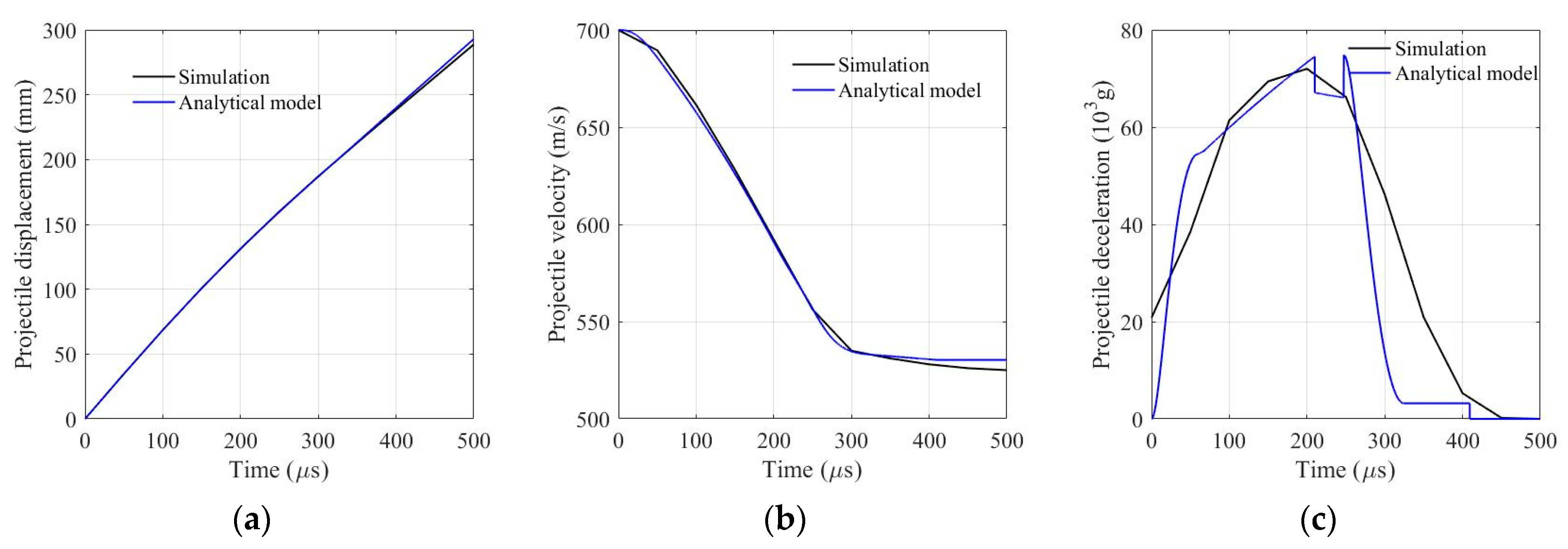
SC walls with a 200-mm thick concrete panel and a 3-mm thick steel plate were studied to validate the analytical model with respect to numerical results in which the projectile striking velocity was 700 m/s.
The projectile movement process, projectile velocity history, as well as projectile deceleration evolution are plotted in Figure 16. The analytical model has good consistency and regularity with simulation results concerning projectile residual velocity and deceleration history.
It is important to validate the analytical model with different boundary conditions, e.g., various thickness combinations of concrete panel and steel plate, and different projectile striking velocities. SC wall perforation of SC walls of 150, 200 and 300 thickness concrete and 3, 5, 7, 9 and 11 mm thicknesses of steel plate were studied both analytically and numerically. Striking velocities ranging from 650 m/s to 800 m/s were calculated and compared with simulation data. A good match is shown in Figure 17, suggesting the analytical model is validated with FE simulation and thus can be applied to subsequent discussion.

5.4. Rear Steel Plate Effect

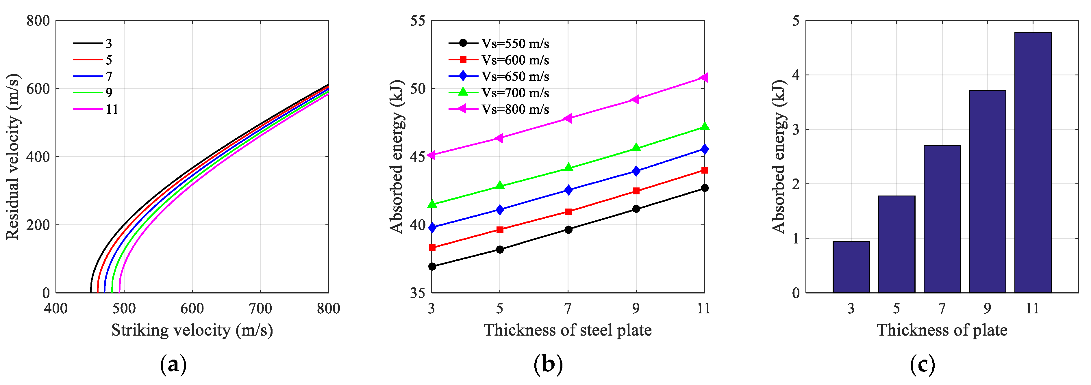
For the SC walls with 200 mm thick concrete panels, the penetration responses, i.e., energy consumption and rear steel plate contribution, were explored analytically by taking into account steel plates with different thickness. In Figure 18a, all five curves have the tendency to converge at increasing striking velocity. Under different striking velocities, the absorbed energy of SC walls with a 200-mm thick concrete panel and different thickness steel plates is shown in Figure 18b, where SC wall consumption energy increases with increasing striking velocity. For the SC walls with a 200 mm thick concrete panel, energy consumed by the rear steel plates is depicted in Figure 18c. The absorbed energy increases with increasing rear steel plate thickness. Under penetration impact of different projectile striking velocities, their energy absorption shows a tendency of linear increase.
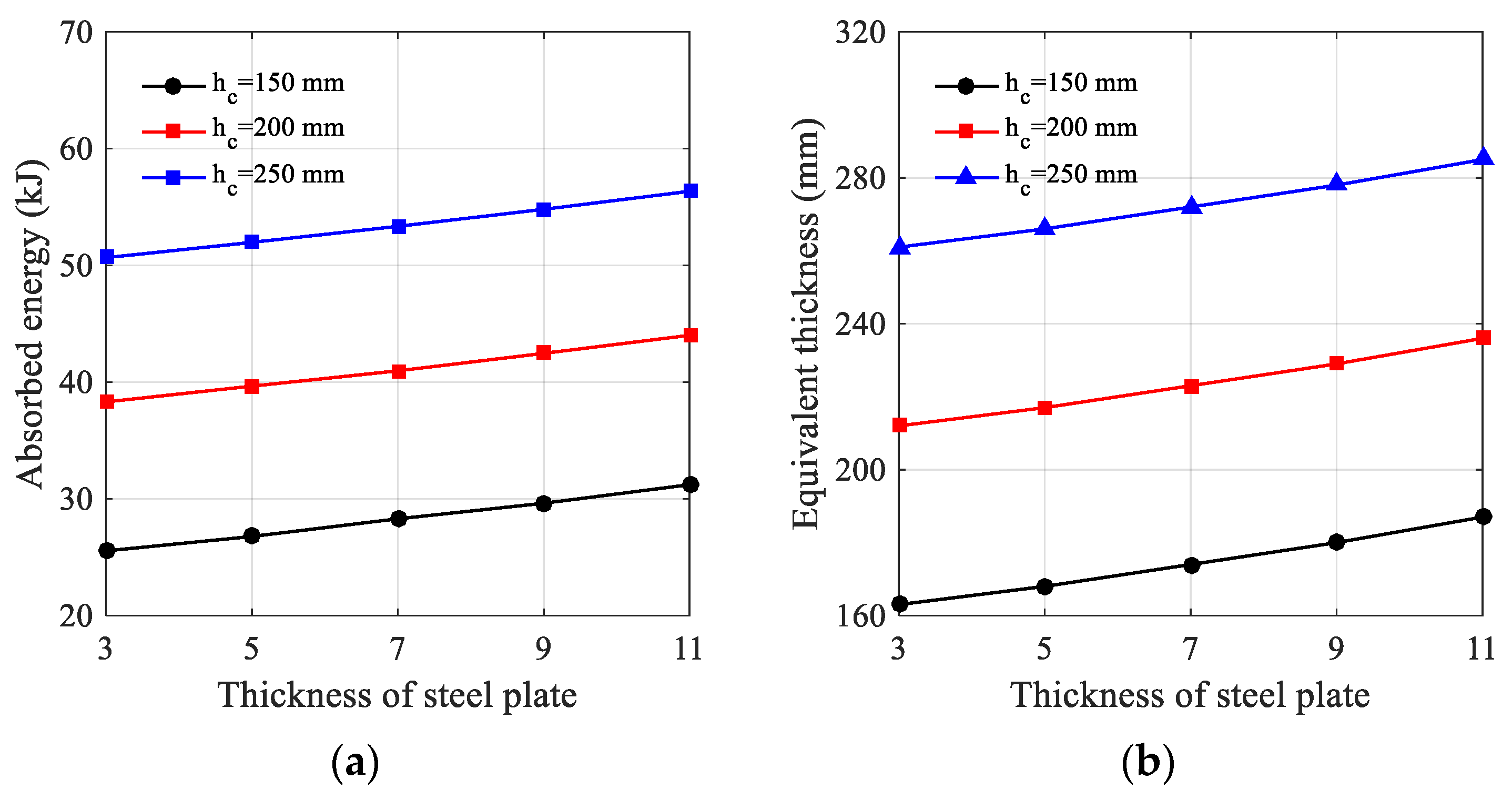
The effect of concrete panel thickness on energy consumption during perforation was studied. Figure 19a shows the absorbed energy of SC walls with different concrete panels. Figure 19b shows the equivalent concrete panel thickness determined for various SC wall perforation with the same ballistic limit.
h eq = h c + 3.06 h t
To evaluate the penetration resistance of SC walls with front concrete panels and rear steel plates, the concept of equivalent thickness of a concrete panel was considered. It was assumed that the equivalent concrete panel thickness had the same ballistic limit as the corresponding SC walls. After data fitting, Equation (19) was derived for the description of equivalent concrete panel thickness in terms of hc and h t of SC walls. This may help researchers to estimate the ballistic limit of SC walls.

6. Conclusions

The penetration resistance of SC walls with various thickness combinations of concrete panels and steel plates was explored both numerically and analytically. Through validation against experimental data, the numerical model and semi-empirical analytical model were further investigated to derive the following conclusions. (1) The attached rear steel plate has a positive influence on impact resistance by preventing the pulverized concrete pieces from flying away. (2) With increasing striking velocity, the rear steel plate has a less pronounced effect on the penetration resistance and thus the residual velocities tend to converge (3) Combining spherical cavity expansion analysis and the thin plate petaling theory, an analytical model with five stages of SC wall perforation was proposed and validated against a numerical simulation. (4) With the same ballistic limit, the equivalent concrete panel thickness can be derived with respect to the SC walls as h eq = h c + 3.06 h t .

Author Contributions

Conceptualization, X.W. and W.L.; writing—original draft preparation, B.P. and J.F.; writing—review and editing, J.F.; visualization, B.P.; supervision, X.W.; funding acquisition, W.L. and J.F. All authors have read and agreed to the published version of the manuscript.

Funding

This study was funded by the National Natural Science Foundation of China (No. 11902161). The APC was funded by Open Cooperative Innovation Fund of Xi’an Institute of Modern Chemistry (No. SYJJ200321).

Institutional Review Board Statement

Not applicable.

Informed Consent Statement

Not applicable.

Data Availability Statement

Some or all data, models, or code that support the findings of this study are available from the corresponding author upon reasonable request.

Acknowledgments

Jun Feng thanks the Natural Science Foundation of Jiangsu Province (No. BK20170824) and the Major Science and Technology Projects in Shanxi under Grant 20201102003.

Conflicts of Interest

The authors declare no conflict of interest.

References

  1. Thai, D.K.; Kim, S.E.; Bui, T.Q. Modified empirical formulas for predicting the thickness of RC panels under impact loading. Constr. Build. Mater. 2018, 169, 261–275. [Google Scholar] [CrossRef]
  2. Lee, K.; Shin, J.; Kim, K.; Varma, A. Local responses of steel-plate composite walls subjected to impact loads: Intermediate scale tests. Eng. Struct. 2020, 206, 110131. [Google Scholar] [CrossRef]
  3. Zou, D.L.; Sun, J.G.; Wu, H.; Hao, Y.F.; Wang, Z.; Cui, L.F. Experimental and numerical studies on the impact resistance of large-scale liquefied natural gas (LNG) storage outer tank against the accidental missile. Thin-Walled Struct. 2021, 158, 107189. [Google Scholar] [CrossRef]
  4. Remennikov, A.; Ying, K.S.; Uy, B. Static and Dynamic Behaviour of Non-Composite Steel-Concrete-Steel Protective Panels under Large Deformation; Research Publishing Services: Singapore, 2010. [Google Scholar]
  5. Remennikov, A.M.; Kong, S.Y. Numerical simulation and validation of impact response of axially restrained steel-concrete-steel sandwich panels. Compos. Struct. 2012, 94, 3546–3555. [Google Scholar] [CrossRef]
  6. Feng, J.; Sun, W.; Liu, Z.; Chong, C.; Wang, X. An armour-piercing projectile penetration in a double layered target of ultra-high-performance fiber reinforced concrete and armour steel: Experimental and numerical analyses. Mater. Des. 2016, 102, 131–141. [Google Scholar] [CrossRef]
  7. Kojima, I. An experimental study on local behavior of reinforced concrete slabs to missile impact. Nucl. Eng. Des. 1991, 130, 121–132. [Google Scholar] [CrossRef]
  8. Tsubota, H.; Yasai, Y.; Noshika, N.; Morikawa, H.; Uchida, T.; Ohno, T.; Kogure, K. Quantitative studies on impact resistance of reinforced concrete panels with steel plates under impact loading part I: Scaled model impact tests. In Transactions of the 12th SMiRT; International Association for Structural Mechanics in Reactor Technology, IASMiRT: Stuttgart, Germany, 1993; pp. 169–174. [Google Scholar]
  9. Abdel-Kader, M.; Fouda, A. Effect of reinforcement on the response of concrete panels to impact of hard projectiles. Int. J. Impact Eng. 2014, 63, 1–17. [Google Scholar] [CrossRef]
  10. Hashimoto, J.; Takiguchi, K.; Nishimura, K.; Matsuzawa, K.; Tsutsui, M.; Ohashi, Y.; Kojima, I.; Torita, H. Experimental study on behavior of RC panels covered with steel plates subjected to missile impact. In Transactions of the 18th SMiRT; International Association for Structural Mechanics in Reactor Technology, IASMiRT: Beijing, China, 2005; pp. 2604–2615. [Google Scholar]
  11. Mizuno, J.; Sawamoto, Y.; Yamashita, T.; Koshika, N.; Niwa, N.; Suzuki, A. Investigation on impact resistance of steel plate reinforced concrete barriers against aircraft impact part 1: Test program and results. In Transactions of the 18th SMiRT; International Association for Structural Mechanics in Reactor Technology, IASMiRT: Beijing, China, 2005; pp. 2566–2579. [Google Scholar]
  12. Bruhl, J.C.; Varma, A.H.; Johnson, W.H. Design of composite SC walls to prevent perforation from missile impact. Int. J. Impact Eng. 2015, 75, 75–87. [Google Scholar] [CrossRef]
  13. Grisaro, H.; Dancygier, A.N. Assessment of the perforation limit of a composite RC barrier with a rear steel plate to impact of a non-deforming projectile. Int. J. Impact Eng. 2014, 64, 122–136. [Google Scholar] [CrossRef]
  14. Wu, H.; Fang, Q.; Peng, Y.; Gong, Z.M.; Kong, X.Z. Hard projectile perforation on the monolithic and segmented RC panels with a rear steel plate. Int. J. Impact Eng. 2015, 76, 232–250. [Google Scholar] [CrossRef]
  15. Lee, H.K.; Kim, S.E. Comparative assessment of impact resistance of SC and RC panels using finite element analysis. Prog. Nucl. Energy 2016, 90, 105–121. [Google Scholar] [CrossRef]
  16. Feng, J.; Sun, W.; Wang, L.; Chen, L.; Xue, S.; Li, W. Terminal ballistic and static impactive loading on thick concrete target. Constr. Build. Mater. 2020, 251, 118899. [Google Scholar] [CrossRef]
  17. Wierzbicki, T. Petalling of plates under explosive and impact loading. Int. J. Impact Eng. 1999, 22, 935–954. [Google Scholar] [CrossRef]
  18. Bishop, R.F.; Hill, R.; Mott, N.F. The theory of indentation and hardness tests. Proc. Phys. Soc. 2002, 57, 147–159. [Google Scholar] [CrossRef]
  19. Forrestal, M.J.; Luk, V.K. Dynamic spherical cavity-expansion in a compressible elastic-plastic solid. J. Appl. Mech. 1988, 55, 275. [Google Scholar] [CrossRef]
  20. Feng, J.; Li, W.; Wang, X.; Song, M.; Ren, H.; Li, W. Dynamic spherical cavity expansion analysis of rate-dependent concrete material with scale effect. Int. J. Impact Eng. 2015, 84, 24–37. [Google Scholar] [CrossRef]
  21. Forrestal, M.J.; Altman, B.S.; Cargile, J.D.; Hanchak, S.J. An empirical equation for penetration depth of ogive-nose projectiles into concrete targets. Int. J. Impact Eng. 1994, 15, 395–405. [Google Scholar] [CrossRef]
  22. Forrestal, M.J.; Frew, D.J.; Hanchak, S.J.; Brar, N.S. Penetration of grout and concrete targets with ogive-nose steel projectiles. Int. J. Impact Eng. 1996, 18, 465–476. [Google Scholar] [CrossRef] [Green Version]
  23. Forrestal, M.J.; Tzou, D.Y. A spherical cavity-expansion penetration model for concrete targets. Int. J. Solids Struct. 1997, 34, 4127–4146. [Google Scholar] [CrossRef]
  24. Rosenberg, Z.; Dekel, E. The penetration of rigid long rods-revisited. Int. J. Impact Eng. 2009, 36, 551–564. [Google Scholar] [CrossRef]
  25. Kong, X.Z.; Wu, H.; Fang, Q.; Zhang, W.; Xiao, Y.K. Projectile penetration into mortar targets with a broad range of striking velocities: Test and analyses. Int. J. Impact Eng. 2017, 106, 18–29. [Google Scholar] [CrossRef]
  26. Feng, J.; Song, M.; Sun, W.; Wang, L.; Li, W.; Li, W. Thick plain concrete targets subjected to high speed penetration of 30CrMnSiNi2A steel projectiles: Tests and analyses. Int. J. Impact Eng. 2018, 122, 305–317. [Google Scholar] [CrossRef]
  27. Rosenberg, Z.; Vayig, Y.; Malka-Markovitz, A. The scaling issue in the penetration of concrete targets by rigid projectiles-Revisited. Int. J. Impact Eng. 2020, 140, 103561. [Google Scholar] [CrossRef]
  28. Peng, Y.; Wu, H.; Fang, Q.; Gong, Z.M.; Kong, X.Z. A note on the deep penetration and perforation of hard projectiles into thick targets. Int. J. Impact Eng. 2015, 85, 37–44. [Google Scholar] [CrossRef]
  29. Landkof, B.; Goldsmith, W. Petalling of thin, metallic plates during penetration by cylindro-conical projectiles. Int. J. Solids Struct. 1985, 21, 245–266. [Google Scholar] [CrossRef]
  30. Johnson, G.; Beissel, S.; Holmquist, T.; Frew, D. Computed radial stresses in a concrete target penetrated by a steel projectile. In Proceedings of the Structures under Shock and Impact V, Thessaloniki, Greece, 24–26 June 1998; pp. 793–806. [Google Scholar]
  31. Sun, W.; Shi, Z.; Chen, B.; Feng, J. Numerical Study on RC Multilayer Perforation with Application to GA-BP Neural Network Investigation. Civ. Eng. J. 2020, 6, 806–819. [Google Scholar] [CrossRef]
  32. Holmquist, T.J.; Johnson, G.R.; Cook, W.H. A computational constitutive model for concrete subjected to large strains, high strain rates and high pressures. In Proceedings of the 14th International Symposium on Ballistics, Quebec City, QC, Canada, 26–29 September 1993; pp. 591–600. [Google Scholar]
  33. Polanco-Loria, M.; Hopperstad, O.S.; Børvik, T.; Berstad, T. Numerical predictions of ballistic limits for concrete slabs using a modified version of the HJC concrete model. Int. J. Impact Eng. 2008, 35, 290–303. [Google Scholar] [CrossRef]
  34. Johnson, G.R.; Cook, W.H. A constitutive model and data for materials subjected to large strains, high strain rates, and high temperatures. In Proceedings of the 7th International Symposium on Ballistics, The Hague, The Netherlands, 19–21 April 1983; pp. 541–547. [Google Scholar]
  35. Kurtaran, H.; Buyuk, M.; Eskandarian, A. Ballistic impact simulation of GT model vehicle door using finite element method. Theor. Appl. Fract. Mech. 2003, 40, 113–121. [Google Scholar] [CrossRef]
  36. Burley, M.; Campbell, J.E.; Dean, J.; Clyne, T.W. Johnson-Cook parameter evaluation from ballistic impact data via iterative FEM modelling. Int. J. Impact Eng. 2018, 112, 180–192. [Google Scholar] [CrossRef]
  37. Zhao, F.C.; Chen, Y.J.; Wang, Y.; Lu, J.S. Damage mechanism and response of reinforced concrete containment structure under internal blast loading. Theor. Appl. Fract. Mech. 2012, 61, 12–20. [Google Scholar] [CrossRef]
  38. Yu, M.; Zha, X.; Ye, J. The influence of joints and composite floor slabs on effective tying of steel structures in preventing progressive collapse. J. Constr. Steel Res. 2010, 66, 442–451. [Google Scholar] [CrossRef] [Green Version]
  39. Wang, X. Adiabatic shear localization for steels based on Johnson-Cook model and second-and fourth-order gradient plasticity models. J. Iron Steel Res. Int. 2007, 14, 56–61. [Google Scholar] [CrossRef]
  40. Oucif, C.; Mauludin, L.M. Numerical modeling of high velocity impact applied to reinforced concrete panel. Undergr. Space 2019, 4, 1–9. [Google Scholar] [CrossRef]
  41. Frew, J.D.; Hanchak, J.S.; Greent, L.M.; Forrestal, J.M. Penetration of concrete targets with ogive-nose steel rods. Int. J. Impact Eng. 1998, 21, 489–497. [Google Scholar] [CrossRef]
  42. Li, J.; Lu, Z.; Zhang, H.; Huang, F. Perforation experiments of concrete targets with residual velocity measurements. Int. J. Impact Eng. 2013, 57, 1–6. [Google Scholar]
  43. Hanchak, J.S.; Forrestal, J.M.; Young, R.E.; Ehrgott, Q.J. Perforation of concrete slabs with 48 MPa (7 ksi) and 140 MPa (20 ksi) unconfined compressive strengths. Int. J. Impact Eng. 1992, 12, 1–7. [Google Scholar] [CrossRef]
  44. Forrestal, M.J. Penetration into dry porous rock. Int. J. Solids Struct. 1986, 22, 1485–1500. [Google Scholar] [CrossRef]
  45. Shi, C.; Wang, M.; Jie, L.; Li, M. A model of depth calculation for projectile penetration into dry sand and comparison with experiments. Int. J. Impact Eng. 2014, 73, 112–122. [Google Scholar] [CrossRef]
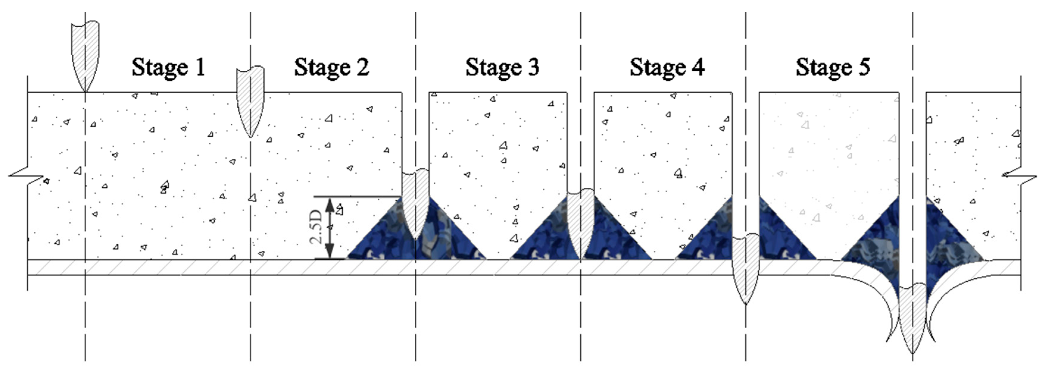
Figure 1. Diagram of a projectile penetrating a steel plate reinforced concrete wall.
Applsci 12 00518 g001
Figure 2. Concrete plate plugging due to perforation [16].
Applsci 12 00518 g002
Figure 3. Petaling diagram [17].
Applsci 12 00518 g003
Figure 4. Projectile dimension [14].
Applsci 12 00518 g004
Figure 5. Geometric dimensioning of SC walls target.
Applsci 12 00518 g005
Figure 6. Finite element model. (a) Projectile; (b) concrete slab; (c) reinforcement mesh; (d) rear steel plate (e) projectile impact SC walls.
Applsci 12 00518 g006aApplsci 12 00518 g006b
Figure 7. Numerical results of projectile perforation on SC walls. (a) Residual velocity comparison; (b) projectile velocity evolutions.
Applsci 12 00518 g007
Figure 8. Damaged contour of SC walls. (a) Rear view of SC walls; (b) section view of concrete panel; (c) numerical results of damaged steel plate; (d) numerical results of damaged concrete panel.
Applsci 12 00518 g008
Figure 9. Overview of the meshed FE model.
Applsci 12 00518 g009
Figure 10. Impact response of an SC wall. (a) von-Mises stress distribution in front concrete panel; (b) von-Mises stress distribution in rear steel plate.
Applsci 12 00518 g010aApplsci 12 00518 g010b
Figure 11. Numerical simulation results. (a) Effects of steel plate; (b) effects of concrete panel; (c) projectile velocity history; (d) residual velocity corresponding to striking velocity.
Applsci 12 00518 g011aApplsci 12 00518 g011b
Figure 12. Front and rear free boundary effect on projectile penetration responses.
Applsci 12 00518 g012
Figure 13. Penetration resistance for panels of different thickness.
Applsci 12 00518 g013
Figure 14. Penetration resistance on the projectile nose.
Applsci 12 00518 g014
Figure 15. Penetration resistant force for five stages.
Applsci 12 00518 g015
Figure 16. Comparison of analytical model and simulation. (a) Projectile displacement history; (b) projectile velocities history; (c) projectile deceleration history.
Applsci 12 00518 g016
Figure 17. Model validation in terms of residual velocity. (a) Different thickness combinations; (b) different projectile impact velocity.
Applsci 12 00518 g017
Figure 18. Results of analytical model for perforation on SC walls with hc = 200 mm. (a) Residual velocity; (b) absorbed energy by SC walls; (c) absorbed energy by steel plate.
Applsci 12 00518 g018
Figure 19. Perforation behavior of SC walls with different thicknesses of concrete panels. (a) Absorbed energy for SC walls; (b) equivalent concrete thickness.
Applsci 12 00518 g019
Table 1. Material parameters of concrete (units: cm-g-μs).
ROGABCNFCTEPSOEFMIN
2.240.14860.791.60.0070.614.1 × 10−44.1× 10−51× 10−60.01
SFMAXPCUCPLULD1D2K1K2K3
7.01.6× 10−40.0010.0080.10.041.00.85−1.712.08
Table 2. Material parameters of steel plate (units: cm-g-μs).
ROGABNCMTMTREPSO
7.8960.8183.5× 10−32.75× 10−30.360.022117932931× 10−6
CPPCSPALLITD1D2D3D4D5C2/P
0.452× 10−5020−0.82.1−0.50.00020.611
Table 3. Element numbers for each component of the SC wall perforation model.
PartProjectileConcrete SlabSteel MeshSteel Plate
Number of elements8001,822,500871218,496
Table 4. Comparison between experiment and simulation.
Vs (m/s)Vr,e (m/s)Vr,n (m/s)
436137187
482207238
544304334
651451474
Table 5. Element numbers for each part.
PartProjectileConcreteRear Steel Plate
Number of elements696376,87550,000
Publisher’s Note: MDPI stays neutral with regard to jurisdictional claims in published maps and institutional affiliations.