Article

A Novel Green Alternative for a Room Prototype Constructed with Entire Recycled PET Bottles and a Green Roof Composed of Waste Materials

by
José de Jesús Pérez Bueno
1,*,
Maria Luisa Mendoza López
2,*,
Flavio Roberto Ceja Soto
1,
José Luis Reyes Araiza
3,
Rubén Ramírez Jiménez
3,
Martha Elva Pérez Ramos
2 and
Alejandro Manzano-Ramírez
4
1
Centro de Investigación y Desarrollo Tecnológico en Electroquímica, Querétaro 76703, Mexico
2
Instituto Tecnológico de Querétaro, Tecnológico Nacional de México, Querétaro 76000, Mexico
3
Facultad de Ingeniería, Universidad Autónoma de Querétaro, Querétaro 76000, Mexico
4
Centro de Investigación y de Estudios Avanzados del Instituto Politécnico Nacional, Unidad Querétaro, Querétaro 76230, Mexico
*
Authors to whom correspondence should be addressed.
Appl. Sci. 2021, 11(17), 7901; https://doi.org/10.3390/app11177901
Submission received: 19 June 2021 / Revised: 24 August 2021 / Accepted: 25 August 2021 / Published: 27 August 2021
(This article belongs to the Special Issue Novel Concept and Technologies of Sustainable Building Design)

Abstract

:

Featured Application

In civil engineering, self-construction, green buildings, and recycling.

Abstract

In this study, we propose a methodology for constructing a prototype room intended primarily for people with low incomes, allowing self-construction practices and upcycling of widely available waste materials in their original form. Mechanical tests were conducted on single bottles of poly(ethylene terephthalate) (PET) filled with different materials as well as on entire PET bottle/concrete blocks. Higher strength was observed when the bottles were in a horizontal position. The mechanical performance of the construction solution adopted for the prototype was not tested, and therefore its structural adequacy was not proven. The insulating multilayer roof was composed of waste plastic bags, two layers of uncapped PET bottles of differing shapes and sizes, another layer of plastic bags, waste cardboard, soil from the site, and a top endemic plant green layer. The PET bottles used in construction were filled with clay from the site, although bottles filled with fly ash achieved better mechanical results. The bottles can also be used uncapped and empty, which would simplify the process considerably by reducing the filling stage. This can be considered to be the main proposal for this type of building. There were almost negligible solid wastes generated, since they were used in the multilayered green roof. From a top view, the prototype mimics the surroundings because the green roof incorporates soil from the site and endemic plants.

1. Introduction

Housing is one of the primary needs of living beings and especially for humans. Locally and globally, there is a pressing need for housing which is directly associated with population growth, with an absolute increase in the global population of about 80 million per year [1,2]. It is also an issue associated with a huge ecological impact [3,4,5,6] due to the occupation of space for neighborhoods and the use of large quantities of building materials [7,8] with direct and indirect impacts as a result of their extraction, processing, and transportation.
The construction industry has been trying to reduce its negative impacts on the environment [6]. Some techniques, designs, innovative materials, and recycling efforts have been implemented in the construction of sustainable buildings [4,6]. The study and use of green roofs have been increasing [9,10,11,12,13,14], mainly for the benefit of internal thermal comfort [11], but also for improving community welfare by mitigating the urban heat island effect [15,16,17]. Green roofs reduce energy consumption and indoor pollution, which is particularly important for low-income people [18].
Today, the construction industry is assuming a retro vogue approach, using locally available building materials such as wood [19,20,21,22], cane [23,24,25], stone [26,27], mud (adobe) [25], jute [28,29,30,31,32], hemp [28], lime [31,32], and bamboo [22]. These materials have countless forms in use and have been modernized.
Poly(ethylene terephthalate) (PET) is widely used, especially for carbonated beverages, drinking water, juices, etc. [33,34,35,36,37]. There have been an increasing number of studies on using PET incorporated into concrete and considering cutting bottles and using them as small pieces or fibers [38,39,40,41,42] rather than using the entire bottle in its original shape. In 2019, according to the National Association for PET Container Resources (NAPCOR), in United States, the recycling rate of PET plastic bottles was 27.9% [43]. Including Canada and Mexico, North America’s PET recycling rate was about 35% in 2019. The use of PET bottles is growing around the world, but its recycling is also increasing. As a building material, PET is readily and broadly available for people to use, especially if the construction technique does not require further processing.
In construction, PET bottles can be used empty or filled with materials with the appropriate properties; the particle size of the filler directly affects the bottle’s mechanical characteristics. For example, fly ash is a waste product in coal-fired power plants, which has excellent close packing properties. Fly ash has light, hollow, spherical-shaped large particles ranging in size from nanometric to micrometric, with an average size of 5–10 microns. This combination of tiny, round particles of different sizes results in excellent close packing, which is beneficial for the mechanical properties of the filled bottles. Global fly ash production is an ever-growing problem, mainly due to the amount of land required for its disposal. This type of waste has been used in construction but with different approaches, such as direct addition to cement and concrete in various proportions, favorably increasing compression strength and workability while reducing costs [44,45]. Nonetheless, coal fly ash is an environmental potential pollutant because of the leaching of toxic heavy metals, such as As, Hg, and Se [46,47,48], depending on the coal surrounding soil [49,50].
Countless alternative materials have been proposed for use in buildings, including composites [51]; resources renewable in the short term [22]; waste materials, such as tires, ferrous and aluminum slags, fly ashes, plastics, and sawdust; and others [44,45,51,52]. All are required to provide structural safety and durability in the long term.
People require dwellings and meeting this need is partly related to their income but also depends on many factors that vary according to the location of the country, the rural or urban condition, year, gender, age, etc. [2]. People living in conditions of extreme poverty and in extreme climates are particularly worrisome. In this study, we propose a methodology for constructing a prototype room intended primarily for low-income people, which involves self-construction practices and upcycling of widely available waste materials in their original form. For construction of the prototype room, we use local resources such as clay and waste materials and include PET bottles, polyethylene bags, glass, cardboard, and so forth, combined with traditional materials. The roof consists of multiple layers of waste materials displayed in such a form to ensure structural integrity, thermal insulation, and durability.
The top layer is designed as a green roof that mimics the natural surroundings by incorporating local soil and endemic plants. Preconstruction measurements for different types of blocks are presented. The measurements include thermal conductivity and mechanical resistance, which are used to evaluate the capability and behavior of PET in such forms in an application in the residential construction industry. Considering the obtained results, we proceeded to the construction of a prototype room based on PET bottles, concrete, and rebar. Certain passive elements were added to the prototype design, such as a row of waste glass bottles in the upper level of three sides of the prototype as a skylight and vents for natural ventilation.
The proposed dwelling prototype is not directly intended to be a counteraction against plastic pollution, since improving waste management systems in all countries is the most effective action [53]. However, during the development of this research, some concerns about the negative health impacts of using PET as a construction material were raised. Nonetheless, many different polymers are present in our daily lives, which includes those in construction materials. The PET bottles were all used for beverages before using them for construction of the room prototype. There was less interaction with the polymer in the building, since the PET bottles were wrapped in a concrete or soil layer, rather than in their original use state.

2. Materials and Methods

2.1. Mechanical Tests of PET Bottles and the PET Blocks

2.1.1. Compression Tests of PET Bottles

The PET bottles were evaluated by compression testing. The tests were conducted using a Galdabini universal testing machine with a capacity of 50 ton (Galdabini; Cardano al Campo, VA, Italy; serial no. 25008) and a loading rate of 2.5 mm/min. The tests were performed with sealed bottles by applying a gradual compression load until failure of the specimens; the total maximum load indicated by the testing was recorded when a fracture appeared in the bottles. The bottles were tested vertically and horizontally relative to their axial axis (Figure 1a–d).
Tests were conducted on six different sample types: (a) empty PET bottles, (b) PET bottles filled with clay from the prototype site, (c) PET bottles filled with sand from the site and saturated with water, (d) PET bottles filled by combining locally available light volcanic rocks and sand, (e) PET bottles filled with gravel and sand, and (f) PET bottles filled with fly ash. The bottles were rammed while filling to ensure close packing without voids, especially those caused by handling the container.

2.1.2. Building Blocks Composed of PET Bottles

The preparation for manufacturing of the blocks was as follows:
(a)
The blocks were prepared using 600 mL PET bottles that were wrapped with a galvanized wire mesh (Figure 2a) to fulfill two objectives: (1) to act as a confining material for the plastic bottles and (2) to serve as mortar reinforcement to help improve the mechanical properties of the entire building element.
(b)
The conventional mortar was fabricated by mixing cement, lime, and sand with volume proportions of 1:0.5:4 (Figure 2b). It exhibited a high fluidity, being easily poured, and the presence of voids was minimized.
(c)
The bottles were distributed in a trapezoidal shape. The mortar was poured into the mold, in which the bottles were previously ordered and wrapped in mesh (Figure 2c). Then, these were cured for fifteen days (Figure 2d).
(d)
The block was removed from the mold. Figure 2 shows the sequence for the preparation of blocks with PET bottles. Different configurations were designed, but only one was prepared and tested. It had a trapezoidal shape with two rows, the bottom row with five bottles and the top row with four bottles.

2.1.3. Compressive Tests of Concrete/PET Bottle Blocks

The procedure for the compression tests of the blocks was similar to that used for PET bottles alone. The tests were conducted on blocks in both positions, i.e., horizontal and vertical, relative to their placement within concrete blocks. Fine sand (sand passing a no. 100 sieve, <150 μm) was placed on the support surface to ensure that the compression load was uniformly distributed over the bearing surfaces. After some preliminary load tests, the blocks had no galvanized wire nets due to preparation difficulty and the intended use for a self-construction process by briefly trained people. However, metallic wire nets were used in the housing prototype and thermal conductivity tests.

2.2. Measurement of Thermal Conductivity in Concrete/PET Bottle Blocks

2.2.1. Description of the Procedure

Thermal conductivity was measured with the guarded hot-plate apparatus setup according to the ASTM C177 standard [54] for steady-state heat flux (Figure 3a–e). Samples measuring 300 × 300 × 85 mm were used [55]. Thermal conductivity was calculated using Equation (1) as follows:
k = e 1 / 2 P Δ T   A
where k is thermal conductivity (W/m °C), e is the block thickness (m), P is the electrical power (W), ΔT is the temperature difference between the cold face and the hot face (°C), and A is the area of the material perpendicular to the heat flow (m2). Here, P = V × I, where V is the applied voltage (volts) and I is the amperage.

2.2.2. Description of the Appliance Components

The hot plate was composed of a resistance with two electrical circuits, a central circuit, and a surrounding circuit. The central circuit had dimensions of 130 × 130 mm. The central circuit was powered by a variable voltage source, and a Watlow SD powered the guard circuit® series controller (Watlow; Santa Clara, CA, USA) for homogeneous heat distribution.
For the thermocouples, seventeen k-type thermocouples were used. Eight thermocouples were placed on each sample. Four thermocouples were placed on the cold side and four on the hot side per sample, all of them at the level of the central circuit. An additional thermocouple was fitted for monitoring the storage area temperature.
The electronic DAQ-ACPC-1216 card was used for the acquisition of generated data. It had sixteen measurement channels with a resolution of 9 to 12 bits and a speed of 2.5 to 10 kHz.
The Watlow SD® temperature controller was monitored and controlled by the thermocouple located in the guard area of the hot plate to maintain a uniform temperature throughout the hot plate.
A variable auto transformer manufactured by STACO® model 3PN10110B (STACO; Cleveland, OH, USA) was used. It had a capacity within the range 0 to 140 V and 10 A. This source fed the central circuit of the hot plate. The voltage and current were used, according to the operator’s criteria.
DASYLab software (DASYLab 2020, V15, Logicbus, San Diego, CA, USA) was used to record the temperatures released by the monitoring system. It was used in the interface with the DAQ-ACPC-1216 card.

3. Results and Discussion

3.1. Sustainability

The term sustainable has various definitions, which can cause controversy when the term is used ambiguously in a broad range of subjects and contexts. We considered some characteristics of the sustainable housing concept, which, without any hierarchy, are as follows:
  • Sustainable housing should meet the basic human needs to safeguard people from weather conditions and provide a space sufficiently appropriate for living.
  • Sustainable housing should have a bioclimatic design that involves the use of natural resources, through both passive systems in construction design and active systems such as appropriate technologies.
  • Sustainable housing should use energy efficiently and incorporate alternative energy sources with a negligible production of CO2.
  • Sustainable housing should constitute an element for conforming to an organized system with sustainable social development through land use planning, including comprehensive logistics for services.
  • The same construction type, individually and as an integral system, should favor natural heritage conservation, which includes minimizing the impacts on the environment.
  • Materials used in construction should be regional, renewable in the short term, and with consideration of their complete cycle, with viability for upcycling or recycling.
These characteristics constitute some generalized ideas in society about sustainable housing, in which awareness has been increasing that a consumptive lifestyle endangers its future.

3.2. Mechanical Tests of PET Bottles and Blocks

3.2.1. Compression Tests of PET Bottles

We had various primary aims for developing the prototype room described here. The prototype was primarily intended for people with low incomes, allowing self-construction practices and upcycling of widely available waste materials in their original form and without further processing. Some of the above-described sustainable housing concepts were incorporated.
The construction of the prototype includes waste materials and more upcycling than recycling, since the bottles were not cut, painted, or reprocessed, minimizing the use of energy and time. In the case of PET, recycling involves mixing with pure materials since its polymeric chains are partitioned in the recycling process, necessitating the addition of new PET. Conversely, glass conserves its properties when recycled, but the recycling process involves energy consumption to transform raw materials into products. Intending to use entire PET bottles, these were tested as conforming blocks and individually filled with widely available materials of different particle sizes.
Figure 1 shows the compression tests of individual PET bottles, both horizontal and vertical. Initially, the deformations for the vertical position were consistently wrinkles around the neck and, subsequently, open fractures that exposed the filler. The horizontal position tests usually did not show shedding of the filler and consisted of axial fractures or occasional cuts around the cylinder compression area.
Figure 1d shows the bottleneck as the weak point in the bottles tested in the vertical position. The main difference in the vertical position tests was that the shape changed twice from narrow to wide along the axis. The force lines had a component directed to the axis in the narrow areas and the outside in the wide areas. Proportionally, the force lines were more concentrated, corresponding to the size of the area. This was the reason for the first deformation around the bottleneck, which had a wrinkle directed to the interior. Usually, the necks of the bottles were reduced to approximately 15% of their height. The final fracture appeared in the middle of the wide area of the bottle, directed outside and spilling the filler.
The data collected from the tests, shown in Table 1, indicated that the bottles more strongly resisted compression in a horizontal position, regardless of the filler material used. Nevertheless, the bottle changed during the horizontal test from round to flat. The contact area increased from punctual to very wide, with an estimated surface of 78 cm2, which was similar at both the top and bottom. The contact area remained almost unchanged during the vertical compression test, except for a small deformation at the bottom. The upper areas of contact were estimated to be approxiately 6.6 cm2. The bottom areas usually had five contact circles of similar radii of 0.85 cm and an approximate area of 11.35 cm2. In general, a comparison between horizontal and vertical positions still favored the former.
Table 1 shows the maximum load of a PET bottle under compression for the vertical and horizontal positions. Six main combinations of fillers were tested: air, dry sand, sand/water, sand/gravel, sand/tezontle (locally available construction material of light volcanic rocks), and fly ash. In the vertical position, two load charges were registered, i.e., one corresponding to the first deformation of the bottlenecks and the other for the fracture that spilled the filler. The test related to sand/water was intended to fill the voids, which was not ultimately achieved, even after 24 h of immersion of an uncapped bottle. The voids remained, but the sand became wet.
During the tests with sand/gravel, sharp points of the gravel drilled the bottles, causing premature failures. In contrast, drilling did not occur during the sand/tezontle tests, since the volcanic rocks did not have sharp points, resulting in the best performance. In the vertical-position tests, the fly ash fines showed high capacity to distribute the force. The value averaged 10.22 ton, with tests ranging from 6 to greater than 20 ton. The recorded high values mainly occurred at the points of having spilled material, indicating a fracture and resulting in plastic without clear failure points because of the flexibility of the PET envelopes. For the vertical-position test, sand/water and wet sand showed distinctively high values.
The use of complete PET bottles as building elements may be favorable in the horizontal position, based on the results of the compression tests and also considering them as a system and their forms of failure. The vertical position, initially 24 cm in height, decreased approximately 15% due to deformation around the neck and 20% when fractures appeared. Moreover, the filler materials were spilled.
Higher strength to load was observed in the vertical tests with the sand/gravel mixture. Horizontal tests indicated that the best filler material was fly ash, mainly due to its particle density, size, and shape. The sizes of the particles, named cenospheres, were about 5 to 10 microns and had a hollow spherical shape. These were not used for filling bottles for the prototype, since they are not widely accessible to most people, and considering sustainable issues related to specialized transport of these material over long distances, even though the final disposition of this residue can be generated in large quantities. The clayed soil from the site was satisfactorily used for filling the PET bottles. As proven by the small section at the left side of the window, the bottles can also be used uncapped and empty, which significantly simplifies the process and reduces the filling stage. This can be considered to be the main proposal for the building in this study.

3.2.2. Compression Tests of Building Blocks Composed of PET Bottles

The tests showed that the average maximum compressive load was approximately 14.7 kN when applied to the bottles in the upright position. When the blocks were composed of bottles in the horizontal position, the load increased to 29.4 kN. Figure 4a–d shows the compression setup before and after compression. In Figure 4b, the block tested with bottles in the vertical position had more and larger fractures than in the horizontal case. The above is not necessarily related to the compression tests of single bottles, which had higher compressive strength when tested horizontally. The compressive loads on the blocks were supported mainly by the concrete, and, as a result, the PET bottles had low deformation before the block cracked. The fractures propagated along the border between the PET bottles and the concrete in the vertical case.
We identified serious limitations in the use of blocks composed of PET bottles/concrete for building the prototype room. Three main findings were identified, which finally prevented their use for construction: (1) the mechanical properties diminished when using the bottles since fractures propagated along their interface with the concrete; (2) they required more concrete than commonly used hollow commercial blocks; and (3) they were heavy and difficult to prepare, which increased the difficulty of moving the blocks to upper areas by one or two persons. The preparation of a large number of blocks for building a room would require work, material, time, and higher costs than for commercial blocks and would have a larger environmental impact. Due to the above disadvantages, evidenced by preparing and testing the blocks incorporating PET bottles, we decided not to use them in the prototype room-building process.
The reason to choose a 5 × 4 configuration for the bottles was associated with the work and time required for making each piece. By having a fewer number of bottles and more concrete, the results of the load test were better, such as using 4 × 4 or 4 × 3 bottles per row. The main concern was that the bottle surfaces acted as crack pathways. In addition, the net avoided having collapses of the pieces but did not change the fissures in the concrete. Nonetheless, much time, concrete, and work are required for making small pieces.
Mechanically, the blocks showed low strength at the junction points of the bottles. As such, even light loads caused fractures. Some areas lacked concrete, which were always weak zones. The block mechanical properties were dependent on the position of the bottles; in the horizontal position, their strength was higher than in the vertical position. This was not associated with the behavior of single bottles under compression tests since the bottles did not change shape. Instead, the vertical position favored the propagation of cracks along the PET/concrete interface.
On the basis of the above results obtained by testing trapezoidal building blocks incorporating PET bottles, they were not used for the room prototype; instead, a configuration of confined stacks of PET bottles between concrete columns and metallic nets was chosen. The bottles were alternated between each row to maintain balance and improve the stability of the wall. The blocks were not a suitable option whether considering their structural characteristics or other factors, such as cost, weight, handling, preparation time, etc. Nonetheless, the results are included as a valuable negative outcome worthy of sharing, which support the proposed alternative.

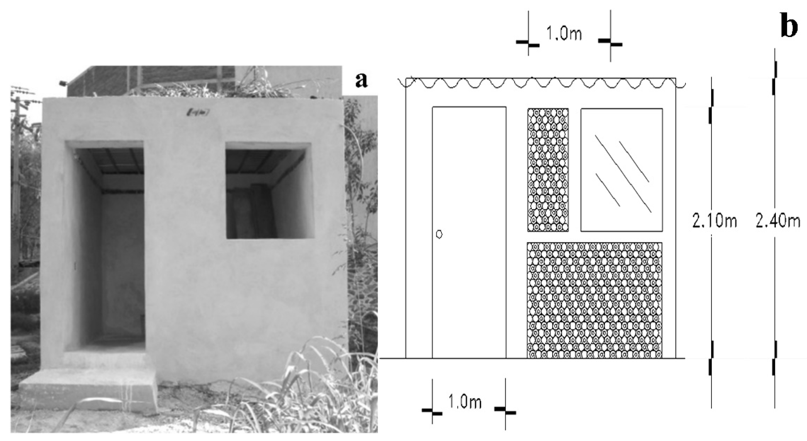
3.3. Construction of a Room Prototype with Waste Materials

After analyzing the feasibility of building a prototype with concrete/PET bottle blocks, the procedure for construction was outlined. The prototype based on PET bottles was built in eight stages, as described in the following eight sections.

3.3.1. The Stone Masonry Foundation and Reinforced Concrete Columns

The foundation was constructed in a traditional manner according to the expansive characteristics of the clay at the site, as is commonly conducted locally, and without further variation. This was mainly based on the perspective of social acceptance, which, together with economy and aesthetics, may prevent the introduction of changes to traditionally accepted construction techniques and materials.

3.3.2. PET Bottle Filling with Soil

Soil extracted for the foundation and from around the construction site was used to fill the wall PET bottles. To increase mechanical resistance, the soil in the bottles was repeatedly compacted and vibrated. Then, all of the bottles were tightly capped. The estimated number of PET bottles used for the walls was about 5000.

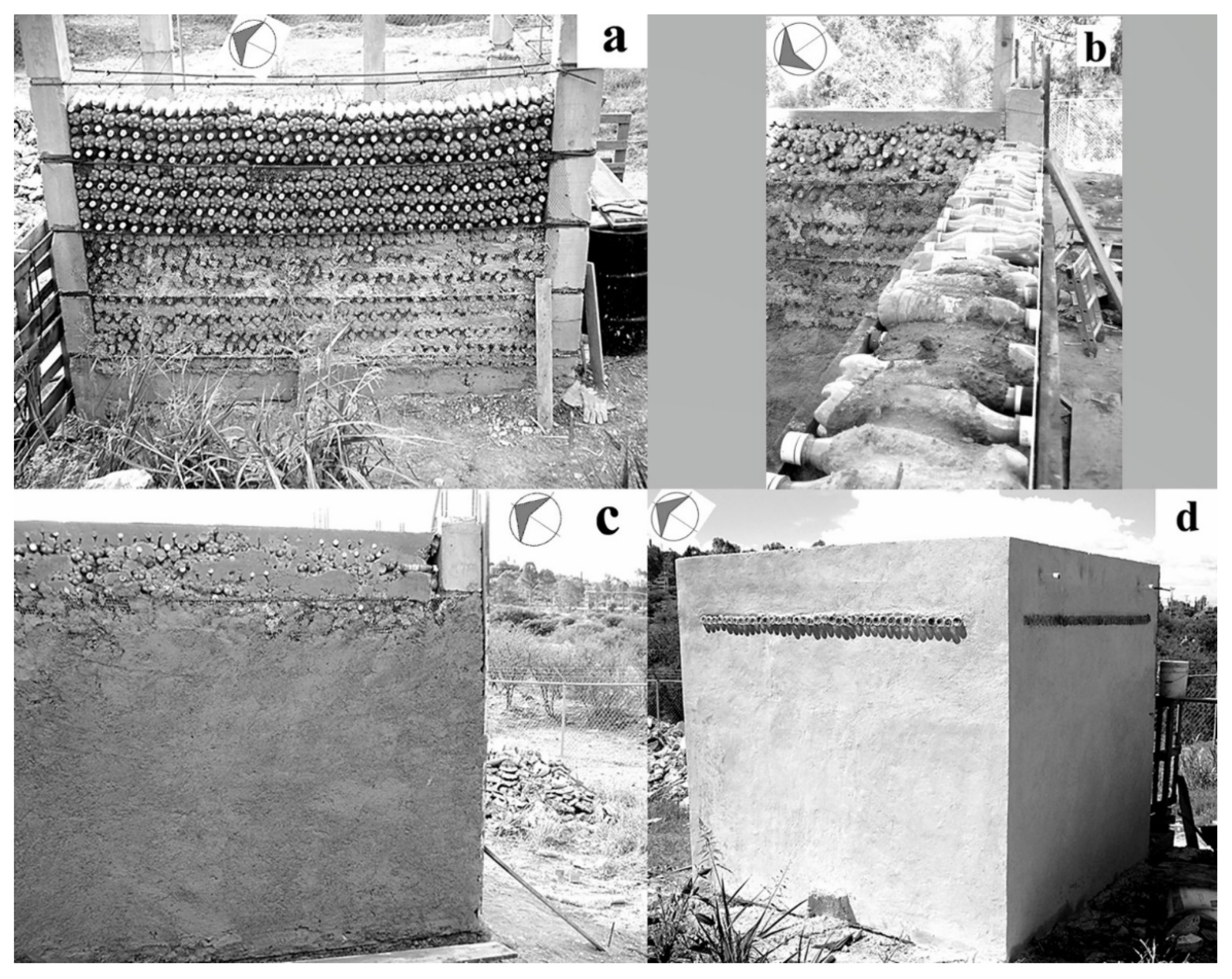
3.3.3. Building of PET Bottle Walls

Once there were enough bottles prepared for construction, the wall building process began. Figure 5 shows the PET bottles in a horizontal position. The pattern alternated the top and bottom of the PET bottles distributed in rows. This order considered the form of the bottles to increase the stability; otherwise, their centers of gravity would be displaced, causing a collapse. Alternatively, the bottles in each row could be alternated between bottom and top, but this packing scheme would form diagonal rows that could result in cracks or collapse. Entire rows having PET bottles aligned facilitated placing the electrical wiring. The stability of the walls was ensured by the confinement induced by reinforced concrete columns; without them, it was not possible to form the stack. The choice was based on preliminary attempts related to the stability of a single and a double stack. They were proven with both empty and filled bottles.

3.3.4. Confinement Perpendicular to the Walls

Two options were proposed for the confinement perpendicular to the walls. The first proposal was to place reinforced concrete horizontal elements along the height of the columns, also joining them. The second proposal consisted of rebar between concrete columns with about 1.2 m of separation. They were moored with gauge wires with about 0.5 m of separation. The second proposal was considered to be easier and provided distributed reinforcement. Finally, each side had five rows of rebar, except the front side, which appeared similar to the first proposal due in part to the window. Figure 5a shows the placement of the rebar anchored to the columns.

3.3.5. Wrapping with Galvanized Wire Nets

Figure 5a,b shows the initial placement of the metallic net at the bottom and covering the entire wall, respectively. In both images, the area with the net had already been covered by an initial mortar layer. In this layer, the mortar used had a high cement content. In Figure 5a, the shadow in the right column is the mesh, which is difficult to notice because of its size. The utility of the mesh was evident for providing stability and for applying the wall surface finishing.

3.3.6. Covering Walls with Mortar

Figure 5c shows the PET bottle wall covered with mortar. The wall thickness increased by about 5 cm (two inches) for each side. A single bottle was originally 23.5 cm high, therefore, the walls were about 33 cm thick. Figure 5d shows a side view of the finished walls of the room prototype.

3.3.7. Area for Skylights

There were three lines of skylights, one for each wall except the façade. They were composed of waste glass bottles, which were of different colors, such as amber, green, blue, and transparent. The bottle bottoms faced outside and inside because there were two opposite bottles with the necks side by side in the middle of the wall. The bottles’ bottoms were aligned in the inner sides of the walls and protruding 5 cm (2”) on the outer sides. This proved to be beneficial for catching daylight, serving as waveguides for light.
The space between each bottle was not filled intentionally to allow natural ventilation; internal curtains can regulate access to air in the room. This is particularly important considering that indoor air pollution is a direct cause of mortality in low-income households, mostly affecting women and children [18]. Figure 5d shows the outer protuberance of the waste glass bottle row projecting a shadow under sunlight. Figure 5a shows the inner side, with the bottom of the bottles aligned with the wall level. The glass bottles were inserted below the concrete beam, which was constructed before placing the bottles, therefore, the glass bottles were not a construction cost element.

3.3.8. Multilayered Roof

The insulating multilayer was composed of waste plastic bags intercalated to cover the three galvanized sheets measuring 3.05 m long and 85 cm wide. There were two layers of uncapped PET bottles having different shapes and sizes. The layer of waste cardboard of cement and lime and waste plastic bags provided stability to set the top black clay soil from the site, which was high in montmorillonite content. Finally, endemic plants from around the construction site were freely allowed to grow.
Figure 6a shows the six tubular steel profiles and an internal view of the corrugated galvanized sheets; Figure 6b shows an external view of their placement. A small additional wall transformed the roof into a flowerbed, complemented by two PVC pipes at the prototype’s left and right sides to allow drainage of excess rainwater.
Figure 6c shows an upper view of the roof construction with areas at different stages. The insulating multilayer was composed of waste materials and an endemic plant top layer. The use of waste polyethylene bags provides an alternative of environmental concern given their disposal in large quantities; they can be used as a waterproof layer when adequately ordered without using commercial paints.
About 1000 PET bottles were used for the roof. They were uncapped to avoid susceptibility to temperature changes since the confined inner air, when sealed, significantly expands or contracts the bottles. Since the wall construction required bottles of the same size and shape, all remaining bottles were used for the roof, independent of their size and shape, but ordered into two layers.
The residues of the construction process, such as the cardboard from the cement sacks, were incorporated into the roof. Soil from the site was used for the green roof. This soil was, in part, constituted of montmorillonite, which conferred specific properties that proved to be useful in this case. Rainwater and wind can barely erode this soil, and the top layer protects the bottles from UV radiation and wind. Finally, Figure 6d shows the green layer of endemic plants. They do not require special care but are absent half of the year, particularly in the winter. It was proposed, but not yet implemented, to cultivate castor oil plants (Ricinus communi), which are already present in the surrounding area and can provide wide shading and subsist on rainwater.
Figure 7a shows a front view of the room prototype without a door or window. Figure 7b shows the initial diagram of the prototype, which was not completed in full. In the area at the side of the window, uncapped empty PET bottles were placed for conducting posterior thermal tests.

3.4. Thermal Conductivity of Concrete/PET Bottle Blocks

The data needed for calculating thermal conductivity were the temperature differences between faces, the electric power, the area of measurement, and the samples’ thicknesses. The tests were performed following the hot plate method. Two tests were conducted under different conditions, and similar results were obtained. The results are provided in Table 2, where the voltage was different for each test. The average thermal conductivity was 0.32 W/m °C. Therefore, the specially prepared concrete/PET bottle blocks, which copied the characteristics of the prototype walls, were considered to be good thermal insulators.
The thermal conductivity of concrete/PET bottle blocks was about 0.3 W/m °C, which is considered to be appropriate for a system emulating the prototype walls. In comparison, adobe thermal conductivity is approximately from 0.5 to 0.7 W/m °C, which is regarded as an excellent thermal insulator [25,51,52,54,56]. The tested PET bottle/concrete system had better insulating characteristics. Notably, the blocks used for mechanical tests were different from the blocks used for thermal conductivity analysis due to dimensional restrictions. The prototype was built after mechanical tests and before thermal conductivity tests with characteristics more similar to these latter blocks.

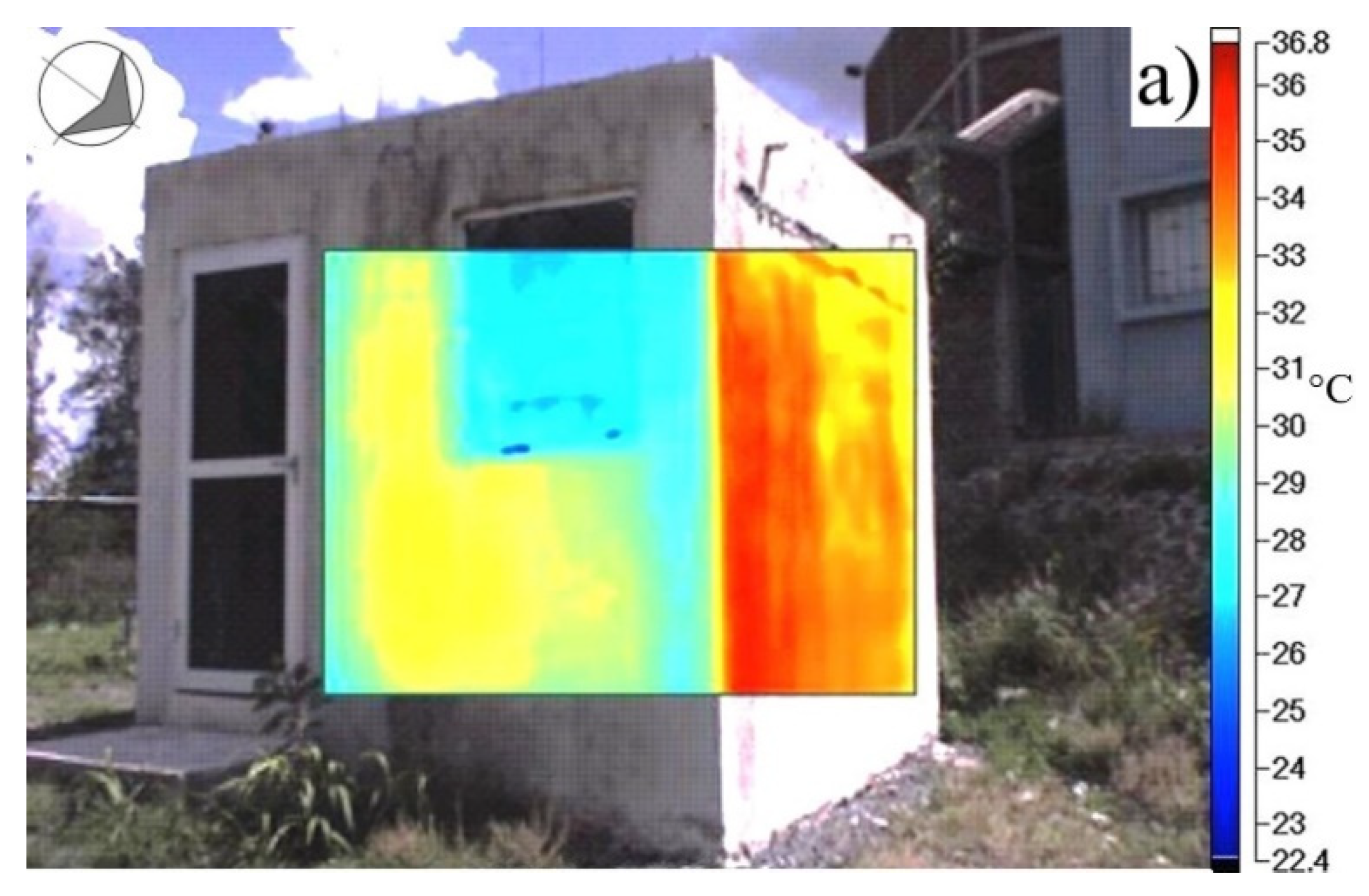
3.5. Thermal Images of the Prototype Structure of Concrete/PET Bottle Blocks

The constructed prototype was monitored using an infrared camera (PCE-TC 4). Figure 8 shows the thermal images overlayed on the visible-light pictures of the external walls and the roof with black soil and endemic plants. The inserted rectangle on the upper left corner indicates the north position. On the northern wall, receiving the sunlight, the temperature was about 36 °C. On the black soil, the temperature was about 45 °C, and it rose up to 60 °C. The thermal images allowed us to identify areas that accumulated humidity. The internal temperatures remained stable at about ±2 °C for a one-year period independent of day/night and season. During the one-year period, the inner temperature and the relative humidity were in the range 10–28 °C and 20–80%, respectively [12,52].

4. Conclusions

A prototype room based on the use of entire PET bottles was constructed. The building methodology was adapted, and other complementary waste materials (recycled or upcycled) were incorporated.
The low mechanical strength of empty PET bottles was increased using different fillers, which contributed by transferring the load. The method of stacking the bottles to constitute the wall core was horizontal because the compression test results indicated that this orientation had greater strength. The PET blocks had greater strength with the bottles in a horizontal position. This was not associated with the results of single-bottle compression tests. The inner bottles did not change in shape. In the vertical position case, fractures propagated along the boundary between the PET bottles and the concrete.
We identified serious limitations in the use of blocks composed of PET bottles and concrete for building the prototype room. Three main aspects were identified, which finally prevented their use for building the prototype room: (1) the mechanical properties decrease using the bottles since fractures propagate along their interface with the concrete, (2) they use more concrete than commonly used hollow commercial blocks, and (3) they are heavy and difficult to prepare. Nonetheless, the results were included, as they describe a valuable, negative outcome, which supports the alternative proposed.
The tested PET bottle/concrete system has better insulation characteristics than the reported values for adobe. The solid wastes generated during the construction of the prototype were almost negligible since they were used in the multilayered green roof. The prototype resembles the surrounding area from a top view due to the green roof that includes soil and endemic plants from the local area.
The insulating multilayer roof was composed of waste plastic bags, two layers of uncapped PET bottles of differing shapes and sizes, a second layer of plastic bags, waste cardboard, soil from the site, and a top layer of endemic plants. The use of waste polyethylene bags attempted to account for both an alternative for environmental concerns about their disposal in large quantities and as a waterproof layer when adequately ordered.
The mechanical performance of the construction solution adopted for the prototype was not tested and, therefore, its structural adequacy was not proven. The entire process was accomplished in three months by only two fully dedicated persons, ranging from picking the PET bottles, to door and window installation, with a roof placed in a single day by one person. The waste PET bottles used in construction were filled with clayey soil from the site. Although PET bottle filling with fly ash produced better mechanical results, they were not included in the construction or suggested for such purpose because of sustainability concerns. As proven by the small section at the left side of the window, the bottles can be used uncapped and empty, which can highly simplify the process and reduce the filling stage. This can be considered the main proposal for the type of building presented in this study.

Author Contributions

Conceptualization, J.d.J.P.B., M.L.M.L., J.L.R.A., R.R.J. and A.M.-R.; methodology, J.d.J.P.B., M.L.M.L., F.R.C.S., J.L.R.A., R.R.J., M.E.P.R. and A.M.-R.; validation, J.d.J.P.B. and M.L.M.L.; formal analysis, J.d.J.P.B., M.L.M.L., F.R.C.S., J.L.R.A., R.R.J., M.E.P.R. and A.M.-R.; investigation, J.d.J.P.B., M.L.M.L., F.R.C.S., J.L.R.A., R.R.J., M.E.P.R. and A.M.-R.; resources, J.d.J.P.B., M.L.M.L. and M.E.P.R.; data curation, J.d.J.P.B.; writing—original draft preparation, J.d.J.P.B. and M.L.M.L.; writing—review and editing, J.d.J.P.B. and M.L.M.L.; visualization, J.d.J.P.B. and M.L.M.L.; supervision, J.d.J.P.B. and M.L.M.L.; project administration, J.d.J.P.B.; funding acquisition, J.d.J.P.B. All authors have read and agreed to the published version of the manuscript.

Funding

This research was funded by CONACYT, grant numbers COAH-2006-C05-62059, QRO-2010-C02-149297, QRO-2010-C02-149-326, and 315878 (LANIAUTO) and the National Laboratory of Graphenic Materials, grant 315799. The authors acknowledge the financial support received from Fondo Sectorial CONACYT-SENER Sustentabilidad Energética through grant 207450, Centro Mexicano de Innovación en Energía Solar (CeMIESol), within strategic project No. P62, Prototype hybrid system of a supercritical CO2 expander with flat polycarbonate mirrors on automated heliostats.

Institutional Review Board Statement

Not applicable.

Informed Consent Statement

Not applicable.

Data Availability Statement

Not applicable.

Acknowledgments

The authors want to thank Juan Mendoza García, Juan Pablo Pérez Ramos, and Edain Belen Pérez Mendoza for their efforts and valuable contribution to the prototype building.

Conflicts of Interest

The authors declare no conflict of interest. The funders had no role in the design of the study; in the collection, analyses, or interpretation of data; in the writing of the manuscript; or in the decision to publish the results.

References

  1. World Population Growth. Available online: https://ourworldindata.org/world-population-growth (accessed on 8 August 2021).
  2. Income Mountains. Available online: https://www.gapminder.org/fw/income-mountains/ (accessed on 8 August 2021).
  3. Alhazmi, H.; Alduwais, A.K.; Tabbakh, T.; Aljamlani, S.; Alkahlan, B.; Kurdi, A. Environmental Performance of Residential Buildings: A Life Cycle Assessment Study in Saudi Arabia. Sustainability 2021, 13, 3542. [Google Scholar] [CrossRef]
  4. Marjaba, G.E.; Chidiac, S.E.; Kubursi, A.A. Sustainability framework for buildings via data analytics. Build. Environ. 2020, 172, 106730. [Google Scholar] [CrossRef]
  5. Liu, Z.-J.; Pypłacz, P.; Ermakova, M.; Konev, P. Sustainable Construction as a Competitive Advantage. Sustainability 2020, 12, 5946. [Google Scholar] [CrossRef]
  6. Kim, H.-J.; Choi, D.-Y.; Seo, D. Development and Verification of Prototypical Office Buildings Models Using the National Building Energy Consumption Survey in Korea. Sustainability 2021, 13, 3611. [Google Scholar] [CrossRef]
  7. Caldas, L.R.; Saraiva, A.B.; Lucena, A.F.P.; Da Gloria, M.Y.; Santos, A.S.; Filho, R.D.T. Building materials in a circular economy: The case of wood waste as CO2-sink in bio concrete. Resour. Conserv. Recycl. 2021, 166, 105346. [Google Scholar] [CrossRef]
  8. Uemura Silva, V.; Nascimento, M.F.; Resende Oliveira, P.; Panzera, T.H.; Rezende, M.O.; Silva, D.A.L.; Borges de Moura Aquino, V.; Rocco Lahr, F.A.; Christoforo, A.L. Circular vs. linear economy of building materials: A case study for parti-cleboards made of recycled wood and biopolymer vs. conventional particleboards. Constr. Build. Mater. 2021, 285, 122906. [Google Scholar] [CrossRef]
  9. Shafique, M.; Kim, R.; Rafiq, M. Green roof benefits, opportunities and challenges—A review. Renew. Sustain. Energy Rev. 2018, 90, 757–773. [Google Scholar] [CrossRef]
  10. Besir, A.B.; Cuce, E. Green roofs and facades: A comprehensive review. Renew. Sustain. Energy Rev. 2018, 82, 915–939. [Google Scholar] [CrossRef]
  11. Zhang, G.; He, B.-J.; Dewancker, B.J. The maintenance of prefabricated green roofs for preserving cooling performance: A field measurement in the subtropical city of Hangzhou, China. Sustain. Cities Soc. 2020, 61, 102314. [Google Scholar] [CrossRef]
  12. Ceja Soto, F.R.; Pérez Bueno, J.J.; Mendoza López, M.L.; Pérez Ramos, M.E.; Reyes Araiza, J.L.; Ramírez Jiménez, R.; Man-zano-Ramírez, A. Evaluating the Thermal Behavior of a Sustainable Room and Roof Prototype Using Recycled Waste Materials. Recycling 2020, 5, 2. [Google Scholar] [CrossRef] [Green Version]
  13. Cascone, S. Green roof design: State of the art on technology and materials. Sustainability 2019, 11, 3020. [Google Scholar] [CrossRef] [Green Version]
  14. Teotónio, I.; Silva, C.M.; Cruz, C.O. Eco-solutions for urban environments regeneration: The economic value of green roofs. J. Cleaner Prod. 2018, 199, 121–135. [Google Scholar] [CrossRef]
  15. Kucukali, L.F. Applications of satellite image index values to obtain the relation of land use and urban heat island effect. Fresenius Environ. Bull. 2021, 29, 8869–8883. [Google Scholar]
  16. Deilami, K.; Kamruzzaman, M.; Liu, Y. Urban heat island effect: A systematic review of spatio-temporal factors, data, methods, and mitigation measures. Int. J. Appl. Earth Obs. Geoinf. 2018, 67, 30–42. [Google Scholar] [CrossRef]
  17. Guo, A.; Yang, J.; Xiao, X.; Xia (Cecilia), J.; Jin, C.; Li, X. Influences of urban spatial form on urban heat island effects at the community level in China. Sustain. Cities Soc. 2020, 53, 101972. [Google Scholar] [CrossRef]
  18. Indoor Air Pollution. Available online: https://ourworldindata.org/indoor-air-pollution (accessed on 8 August 2021).
  19. Chen, C.; Kuang, Y.; Zhu, S.; Burgert, I.; Keplinger, T.; Gong, A.; Li, T.; Berglund, L.; Eichhorn, S.J.; Hu, L. Structure–property–function relationships of natural and engineered wood. Nat. Rev. Mater. 2020, 5, 642–666. [Google Scholar] [CrossRef]
  20. Lazarevic, D.; Kautto, P.; Antikainen, R. Finland’s wood-frame multi-storey construction innovation system: Analysing motors of creative destruction. For. Policy Econ. 2020, 110, 101861. [Google Scholar] [CrossRef]
  21. Mi, R.; Li, T.; Dalgo, D.; Chen, C.; Kuang, Y.; He, S.; Zhao, X.; Xie, W.; Gan, W.; Zhu, J.; et al. A Clear, Strong, and Thermally Insulated Transparent Wood for Energy Efficient Windows. Adv. Funct. Mater. 2020, 30, 1907511. [Google Scholar] [CrossRef]
  22. Sun, X.; He, M.; Li, Z. Novel engineered wood and bamboo composites for structural applications: State-of-art of manufac-turing technology and mechanical performance evaluation. Constr. Build. Mater. 2020, 249, 118751. [Google Scholar] [CrossRef]
  23. Tsapko, Y.; Bondarenko, O.; Tsapko, A. Research of the efficiency of the fire fighting roof composition for cane. Mat. Sci. Forum 2019, 968, 61–67. [Google Scholar] [CrossRef]
  24. Aksogan, O.; Resatoglu, R.; Binici, H. An environment friendly new insulation material involving waste newsprint papers reinforced by cane stalks. J. Build. Eng. 2018, 15, 33–40. [Google Scholar] [CrossRef]
  25. George, C.; Carlos, E.; David, M. Serious game for the virtual practice of the emplantillado in the constructive system of adobe with reinforced cane. ACM Int. Conf. Proc. Ser. 2017, 99–103. [Google Scholar] [CrossRef] [Green Version]
  26. Vigroux, M.; Eslami, J.; Beaucour, A.-L.; Bourgès, A.; Noumowé, A. High temperature behaviour of various natural building stones. Constr. Build. Mater. 2021, 272, 121629. [Google Scholar] [CrossRef]
  27. Gupta, V.; Pathak, D.K.; Kumar, R.; Miglani, A.; Siddique, S.; Chaudhary, S. Production of colored bi-layered bricks from stone processing wastes: Structural and spectroscopic characterization. Constr. Build. Mater. 2021, 278, 122339. [Google Scholar] [CrossRef]
  28. Bambach, M.R. Compression strength of natural fibre composite plates and sections of flax, jute and hemp. Thin-Walled Struct. 2017, 119, 103–113. [Google Scholar] [CrossRef]
  29. Bansod, P.V.; Mittal, T.; Mohanty, A.R. Study on the Acoustical Properties of Natural Jute Material by Theoretical and Ex-perimental Methods for Building Acoustics Applications. Acoust. Aust. 2016, 44, 457–472. [Google Scholar] [CrossRef]
  30. Devireddy, S.B.R.; Biswas, S. Thermo-physical properties of short banana–jute fiber-reinforced epoxy-based hybrid composites. Proc. Inst. Mech. Eng. Part L: J. Mater. Des. Appl. 2018, 232, 939–951. [Google Scholar] [CrossRef]
  31. Garikapati, K.P.; Sadeghian, P. Mechanical behavior of flax-lime concrete blocks made of waste flax shives and lime binder reinforced with jute fabric. J. Build. Eng. 2020, 29, 101187. [Google Scholar] [CrossRef]
  32. Formisano, A.; Chiumiento, G.; Fabbrocino, F. Experimentation on lime mortars reinforced with jute fibres: Mixture workability and mechanical strengths. Lect. Notes Mech. Eng. 2020, 2020, 1869–1880. [Google Scholar] [CrossRef]
  33. Plasticseurope. Plastics—The Facts 2019. An Analysis of European Plastics Production, Demand and Waste Data. Available online: https://www.plasticseurope.org/application/files/1115/7236/4388/FINAL_web_version_Plastics_the_facts2019_14102019.pdf (accessed on 8 August 2021).
  34. Geyer, R.; Jambeck, J.R.; Law, K.L. Production, use, and fate of all plastics ever made. Sci. Adv. 2017, 3, e1700782. [Google Scholar] [CrossRef] [Green Version]
  35. IHS Markit. PET Polymer: Chemical Economics Handbook. Available online: https://ihsmarkit.com/products/pet-polymer-chemical-economics-handbook.html (accessed on 26 August 2021).
  36. Ragaert, K.; Delva, L.; Van Geem, K. Mechanical and chemical recycling of solid plastic waste. Waste Manag. 2017, 69, 24–58. [Google Scholar] [CrossRef]
  37. Tournier, V.; Topham, C.M.; Gilles, A.; David, B.; Folgoas, C.; Moya-Leclair, E.; Kamionka, E.; Desrousseaux, M.-L.; Texier, H.; Gavalda, S.; et al. An engineered PET depolymerase to break down and recycle plastic bottles. Nature 2020, 580, 216–219. [Google Scholar] [CrossRef] [PubMed]
  38. Meza de Luna, A.; Shaikh, F.U.A. Anisotropy and bond behaviour of recycled Polyethylene terephthalate (PET) fibre as con-crete reinforcement. Constr. Build. Mater. 2020, 265, 120331. [Google Scholar] [CrossRef]
  39. Borg, R.P.; Baldacchino, O.; Ferrara, L. Early age performance and mechanical characteristics of recycled PET fibre reinforced concrete. Constr. Build. Mater. 2016, 108, 29–47. [Google Scholar] [CrossRef] [Green Version]
  40. Asdollah-Tabar, M.; Heidari-Rarani, M.; Aliha, M.R.M. The effect of recycled PET bottles on the fracture toughness of polymer concrete. Compos. Commun. 2021, 25, 100684. [Google Scholar] [CrossRef]
  41. Dawood, A.O.; AL-Khazraji, H.; Falih, R.S. Physical and mechanical properties of concrete containing PET wastes as a partial replacement for fine aggregates. Case Stud. Constr. Mater. 2021, 14, e00482. [Google Scholar] [CrossRef]
  42. Meza, A.; Pujadas, P.; López-Carreño, R.D.; Meza, L.M.; Pardo-Bosch, F. Mechanical optimization of concrete with recycled pet fibres based on a statistical-experimental study. Materials 2021, 14, 240. [Google Scholar] [CrossRef]
  43. NAPCOR. 2019 PET Recycling Report. Available online: https://napcor.com/reports-resources (accessed on 8 August 2021).
  44. American Coal Ash Association. Coal Ash Production and Use. Available online: https://www.acaa-usa.org/Portals/9/Files/PDFs/Coal-Ash-Production-and-Use.pdf (accessed on 8 August 2021).
  45. Arenas, C.; Ríos, J.D.; Cifuentes, H.; Peceño, B.; Leiva, C. Experimental study of a noise reducing barrier made of fly ash. Mater. Constr. 2021, 71, e239. [Google Scholar] [CrossRef]
  46. Seki, T.; Nakamura, K.; Ogawa, Y.; Inoue, C. Leaching of As and Se from coal fly ash: Fundamental study for coal fly ash recycling. Environ. Monit. Assess. 2021, 193, 225. [Google Scholar] [CrossRef]
  47. Zhang, L.; Song, Q.; Xu, Z. Arsenic removal and recovery of germanium and tungsten in toxic coal fly ash from lignite by vacuum distillation with a sulfurizing reagent. Environ. Sci. Technol. 2021, 55, 4027–4036. [Google Scholar] [CrossRef]
  48. Singh, S.; Singh, N.P.; Rani, R. Heavy metals leaching characteristics from coal fly ash of three thermal power plants and its adverse effects on environment. Eur. Chem. Bull. 2021, 10, 114–122. [Google Scholar] [CrossRef]
  49. Shakeel, A.; Khan, A.A.; Alharby, H.F.; Bamagoos, A.A.; Tombuloglu, H.; Hakeem, K.R. Evaluation of coal fly ash for modulating the plant growth, yield, and antioxidant properties of daucus carota (L.): A sustainable approach to coal waste recycling. Sustainability 2021, 13, 5116. [Google Scholar] [CrossRef]
  50. Alam, J.; Yadav, V.K.; Yadav, K.K.; Cabral-Pinto, M.M.S.; Tavker, N.; Choudhary, N.; Shukla, A.K.; Ali, F.A.A.; Alhoshan, M.; Hamid, A.A. Recent advances in methods for the recovery of carbon nanominerals and polyaromatic hydrocarbons from coal fly ash and their emerging applications. Crystals 2021, 11, 88. [Google Scholar] [CrossRef]
  51. Lu, X.; Liang, B.; Sheng, X.; Yuan, T.; Qu, J. Enhanced thermal conductivity of polyurethane/wood powder composite phase change materials via incorporating low loading of graphene oxide nanosheets for solar thermal energy storage. Sol. Energy Mater. Sol. Cells 2020, 208, 110391. [Google Scholar] [CrossRef]
  52. Ceja Soto, F.R.; Pérez Bueno, J.J.; Mendoza López, M.L.; Pérez Ramos, M.E.; Reyes Araiza, J.L.; Ramírez Jiménez, R.; Man-zano-Ramírez, A. Sustainability Metrics for Housing and the Thermal Performance Evaluation of a Low-Cost Prototype Made with Poly (Ethylene Terephthalate) Bottles. Recycling 2019, 4, 30. [Google Scholar] [CrossRef] [Green Version]
  53. Plastic Pollution. Available online: https://ourworldindata.org/plastic-pollution#how-does-plastic-impact-wildlife-and-human-health (accessed on 8 August 2021).
  54. ASTM C177–19. Standard Test Method for Steady-State Heat Flux Measurements and Thermal Transmission Properties by Means of the Guarded-Hot-Plate Apparatus; ASTM International: West Conshohocken, PA, USA, 2019. [Google Scholar]
  55. Marín-López, C.; Reyes Araiza, J.L.; Manzano-Ramírez, A.; Rubio Avalos, J.C.; Perez-Bueno, J.J.; Muñiz-Villareal, M.S.; Ventura-Ramos, E.; Vorobiev, Y. Synthesis and Characterization of a Concrete Based on Metakaolin Geopolymer. Inorg. Mater. 2009, 45, 1429–1432. [Google Scholar] [CrossRef]
  56. Cheung, P.K.; Jim, C.Y. Comparing the cooling effects of a tree and a concrete shelter using PET and UTCI. Build. Environ. 2018, 130, 49–61. [Google Scholar] [CrossRef]
Figure 1. General display of compression tests and occurrence of common fractures: (a) Horizontal position for a bottle sealed with air; (b) fly-ash-filled bottle tested in the horizontal position; (c) sand-filled upright bottle; (d) typical fracture in a sand/water-filled upright bottle.
Applsci 11 07901 g001
Figure 2. The process of preparation of a PET/net/concrete-based block: (a) Two PET bottle arrays moored with a galvanized mesh; (b) mortar preparation; (c) PET bottle distribution in two rows; (d) molded piece with a trapezoidal shape.
Applsci 11 07901 g002
Figure 3. Blocks with bottles: (a) Right-side view; (b) left-side view; (c) stacking view of PET bottles; (d) hot plate drawer diagram; (e) opened drawer of hot plates.
Applsci 11 07901 g003
Figure 4. (a) Trapezoidal block with bottles in the vertical position; (b) upright block after compression; (c) trapezoidal block with bottles in the horizontal position; (d) recumbent block after compression.
Applsci 11 07901 g004
Figure 5. (a) Backside view of the PET bottle prototype showing them piled up and the horizontal rebar for reinforcement with the steel net; (b) bottle rows alternating top and bottom with galvanized mesh and concrete; (c) plaster covering the wall; (d) finished lateral structure with a single row of skylights of waste glass bottles on three sides.
Applsci 11 07901 g005
Figure 6. (a) Six steel tubular supports with three corrugated galvanized sheets placed on a 3 × 3 m area; (b) their borders were embedded with a surrounding concrete wall; (c) the multilayer of waste materials with uncapped PET bottles, soil, and a green roof; (d) an upper perspective including the plants.
Applsci 11 07901 g006
Figure 7. The front view of the prototype: (a) Picture taken before installing the door and window; (b) the initial design concept of the façade.
Applsci 11 07901 g007
Figure 8. Thermography images of the finished prototype room (taken at 15:45): (a) Façade view showing a temperature range of 22.4–36.8 °C; (b) top view showing the roof with endemic plants and a temperature range of 24.0–47.1 °C.
Applsci 11 07901 g008aApplsci 11 07901 g008b
Table 1. Maximum load of a PET bottle under compression in both the vertical and horizontal positions *.
Filler MaterialMaximum
Compression (kN)
Vertical Position
Maximum
Compression (kN)
Vertical Position **
Maximum
Compression (kN)
Horizontal Position
Air0.630.240.44
Dry sand1.21.9662.81
Wet sand8.821.6687.375
Sand/gravel9.72.3557.075
Sand/tezontle13.922.2543.25
Fly ash11.271.47100.22
* Coefficient of variation (CV) or relative standard deviation (RSD) was about 10% in three tests. ** Deformation of the bottleneck.
Table 2. Measurements of thermal conductivity by hot plate method.
SamplesTest ConditionsMeasurements
TestBlockVoltage
(V)
Current
(A)
Δx
(m)
Area
(m2)
Power
(W)
Th
(°C)
Tc
(°C)
ΔT
(°C)
Thermal Conductivity
(W/m °C)
118.30.340.000860.0001692.82232.57010.32022.250.32270727
28.30.340.000860.0001692.82233.01011.98021.030.34142828
2115.20.30.000860.0001694.5653.21015.40037.810.306859742
215.20.30.000860.0001694.5651.97714.89037.0870.312841882
Average thermal conductivity:0.3209
Publisher’s Note: MDPI stays neutral with regard to jurisdictional claims in published maps and institutional affiliations.

