Article

Numerical Simulation on Dynamic Behavior of Slab–Column Connections Subjected to Blast Loads

1
Korean Peninsula Infrastructure Special Committee, Korea Institute of Civil Engineering and Building Technology, Goyang-si 10223, Korea
2
Coastal Development and Ocean Energy Research Center, Korea Institute of Ocean Science and Technology, 385 Haeyang-ro, Yeongdo-gu, Busan 49111, Korea
3
Department of Civil and Environmental Engineering, The University of Suwon, Hwaseong-si 18323, Korea
*
Author to whom correspondence should be addressed.
Appl. Sci. 2021, 11(16), 7573; https://doi.org/10.3390/app11167573
Submission received: 23 July 2021 / Revised: 14 August 2021 / Accepted: 15 August 2021 / Published: 18 August 2021
(This article belongs to the Special Issue Blast and Impact Engineering on Structures and Materials)

Abstract

:
Although many studies on the blast-resistant performance of structures have focused mainly on single members such as beams and columns, there is little research on the behavior of joints that are subjected to blast loads. In this study, the structural behavior of a slab–column connection subjected to blast load was investigated using a numerical analysis method. LS-DYNA was used as a finite element analysis program, and in order to improve the accuracy of numerical analysis, mesh size, material model, and simulation method of blast load were determined through preliminary analysis. The effect of different restraints of the joints, depending on the position of the columns in the slab, on the blast resistance performance was investigated. As a result, the highly confined slab-interior column connection showed better behavior than other edge and corner columns. The drop panel installed between the lower column and the slab was effective in improving the blast-resistance performance of the slab–column connection. For a more accurate evaluation of blast resistance performance, it was suggested that various evaluation factors such as ductility ratio, reinforcing stress, and concrete fracture area can be considered along with the support rotation, which is an important evaluation factor suggested by many standards.

1. Introduction

As explosive terrorism and explosion accidents continue to occur around the world, research on the behavior of structures under such extreme situations is increasing [1,2,3]. Most of these studies focus on how single members such as beams, columns, and slabs behave under explosive loads. Since the failure or large deformation of the joint can directly lead to the collapse or malfunction of the entire structural system, the study on the joint behavior is no less important than the study on single members. Although many studies have been conducted on the structural behavior of joints under static and dynamic loads, further studies are still needed to improve the understanding of joint behavior under explosive loads [4,5,6].
In this study, the joints of the columns and slabs were investigated. In particular, the behavior of the joints under blast load was investigated according to the position of the column. In other words, the effect of different restraints of the joints on the blast-resistance performance was observed as the columns were located on the inside, edge, and corner of the slab. In addition, the behavior of slab–column joint with drop panel, which is a square portion provided above the lower column and below the slab, was investigated. Drop panels that provide increased shear strength and moment resistance are expected to be effective in improving the blast-resistance performance of slab–column joints. The experimental approach with explosives is really challenging, expensive, and difficult. Therefore, in this study, numerical analysis, one of the best options to discuss this phenomenon, was performed using LS-DYNA, a general-purpose finite element analysis program whose reliability has been verified through many previous studies [7,8].

2. Literature Review

There are some studies on the structural behavior of the slab–column connections according to the position of columns under static loads. Bianchini et al. (1960) performed tests on a total of 45 specimens of the interior, edge, corner, and isolated columns [9]. As a result, the effective strength of the interior column–slab joint was 75% of the column strength and 1.5 times the slab strength. However, when the column strength exceeds the slab strength by 1.4 times, the effective strength of the column–slab joint at the edge and corner columns is not significantly increased by the restraint of the surrounding slab [9]. McHarg et al. (2000) performed a total of 12 test specimens consisting of column–slab specimens and isolated column specimens [10]. The interior column showed greater axial compressive strength than the isolated column due to the restraint effect of the slab, and also showed ductile behavior [10]. Lee et al. (2007) performed column load transmission experiments depending on the position of the column. As a result, the interior column test specimen has improved ultimate load capacity than the isolated column specimen due to the slab restraint effect [11].
There are also many studies on the structural behavior of slab–column connections under dynamic loads. Some of them experimentally confirmed that the amount of flexural reinforcement affects the seismic behavior of the slab–column joint [12,13,14,15,16]. Some studies have investigated the seismic response of slab–column joints with high-strength concrete (HSC) applied to the slab, and they showed that the specimens with HSC had superior performance in terms of ductility and strength, compared to specimens with conventional normal strength concrete (NSC) [17,18,19,20]. Scotta and Giorgi (2016) performed cyclic experiments on four full-scale exterior slab–column connections made of normal concrete and fiber-reinforced lightweight aggregate concrete [21]. They reported that the addition of steel fibers to the concrete mix improved the hysteretic behavior of slab–column connections [21]. Several researchers have studied the progressive collapse and robustness of building structures due to column or joint collapse [22,23,24,25,26]. Setiawan et al. (2019) performed numerical analysis on slab–column connections subjected to cyclic loading and captured the characteristics of cyclic degradation observed in experiments with nonlinear finite analysis and suggested a simplified design method for punching shear [27].
As shown above, studies dealing with the structural behavior of joints under dynamic loads mainly focus on seismic loads. While there are relatively many experimental and numerical investigations of reinforced concrete (RC) slabs subjected to blast loading [28,29,30,31,32,33,34,35,36,37], there are few studies of slab–column connections. Shahriari et al. (2021) numerically investigated the blast response and progressive collapse of RC structures equipped with viscoelastic dampers [38]. They found that viscoelastic dampers designed for seismic loads resulted in a suitable performance for reducing the response of structures to blast loads [38]. Krauthammer (1999) reported that plastic hinge control through diagonal reinforcing bars can contribute to the improvement of the blast resistance performance of the connections [39]. Lim et al. (2016) have reported the blast-resistance performance of joints of slab-interior and slab-edge columns [40]. However, there is no study on the blast-resistance behavior for the slab-corner column connection and for the relatively large explosive load. Additionally, the method of transmission of the explosive load has not been verified sufficiently in the numerical analysis. Therefore, it is necessary to investigate the blast-resistance performance of slab–column connections depending on the type of the column and the amount of explosive load.
According to the ASCE/SEI (2011), the connection should be designed to resist shear force, axial force, bending moment, and torsion [41]. The effects of rebound are also considered for all connections. The reinforcements in beam–column connections are supposed to comply with details of earthquake-resistant structures according to ASCE/SEI (2011) [41]. There are no other guidelines for the design of blast-resistant slab–column connections. Especially, the material properties in blast events are different in earthquake conditions because of the difference in strain rate. The strain rate is typically over 100 s−1 in blast events and 10−5 s−1 in earthquakes [42]. Therefore, more accurate material properties are needed to design structures subjected to explosive loads comparing to structures subjected to seismic loads.
According to UFC 3-340-02 issued by the US Department of Defense (DoD), support rotation and ductility are selected as criteria for evaluating the structural performance of RC structural members under explosive loads [43]. This criterion assumes that the structural member is effectively resisting the blast load when the support rotation is 2 degrees or less. In addition, ASCE/SEI 59-11 proposes the limit of support rotation for blast-resistant RC structures and also provides a level of protection (LOP) [41]. It is noteworthy that both DoD and ASCE are proposing support rotation as an evaluation factor for the behavior of blast-resistant structures.

3. Numerical Analysis

3.1. Details of Specimens

Details of all slab–column connections are shown in Figure 1. The specimen IC is a statically designed slab-interior column connection. The specimen IC-D has the same reinforcement and shape details as specimen IC, but the drop panel was additionally placed according to ACI 318 (2011) [44] and ACI 352.1R [45]. The specimens EC and CC were designed based on the specimen IC, but the column was located at the edge and corner of the slab, respectively. Accordingly, the specimens EC and CC are confined on three sides and two sides of the connection, respectively, while the specimen IC is confined on all four sides. In general, the effective strength of connections can be improved in static loads when the column in connection is confined by slab [9,46]. To verify the confinement effects, comparative studies were conducted on the behavior of specimens IC, EC, and CC.

3.2. Modeling of Specimens

In order to obtain accurate numerical analysis results, it is necessary to establish an accurate material model. In this study, Mat_072R3 was selected from the concrete material models provided by the analysis program LS-DYNA. This material model reflects the strain-rate effect and has already been found in several studies in the literature to be suitable for analyzing concrete structures under high strain-rate [47,48,49]. However, Mat_072R3 was unable to exhibit local damage caused by explosions, such as crater spalls, which are associated with structural failure and erosion [50]. Therefore, to simulate these characteristics, LS-DYNA’s “Add_Erosion keyword” option was applied to the concrete material model. To model the reinforcing bars, LS-DYNA’s Mat_024 was applied, which is defined as an elastic-plastic material with arbitrary stress–strain curve and an arbitrary strain-rate dependency. The fracture of Mat_024 is based on plastic deformation [49].
Numerical analysis results may vary depending on the mesh size of the element [51,52]. According to the previous studies, when simulating a structure subjected to an explosive load, a mesh size of 25 to 30 mm led to the analysis results most similar to the experimental results [33,53]. In this study, before the main analysis was conducted, various mesh sizes were evaluated in terms of accuracy and efficiency of analysis. In the preliminary analysis, the displacement, stress of reinforcing bars, and fracture shape were investigated in the same way as in the main analysis. Considering the analysis results and the time required for analysis, a mesh size of 20 to 25 mm is considered to be the most reasonable. Therefore, in this study, the concrete mesh is composed of 25 mm cubic, 8-node solid elements.
The interaction between concrete and reinforcing bars has a great influence on the behavior of RC structures. In particular, interactions such as bond–slip are very difficult to simulate. A method of tying nodes was recommended to simulate the structure’s actual behavior and to provide the simplicity of analysis [48,54]. In this study, the nodes of the reinforcing bar and concrete are connected to each other to provide accurate structural performance.
The one-point integration method used in this analysis is effectively applied to dynamic analysis due to its relatively short analysis time. However, there is a risk of creating a zero-energy state that causes a negative volume or creating an element that behaves differently from the actual behavior. In the numerical analysis, the volume of solid elements is generally reduced when subjected to the compressive pressure, but when zero energy is generated inside the solid elements, the negative volume occurs due to the abnormal operation of the element, resulting in an increase in volume, as shown in Figure 2. In this case, the amount of internal energy loss is called hourglass energy. When the hourglass energy is largely generated, it is difficult to ensure the accuracy of the analysis [55,56,57]. Therefore, LS-DYNA’s “Hourglass” option, which can control the accuracy of analysis due to this phenomenon, was applied to the material model [48,58].

3.3. Modeling of Blast Loads

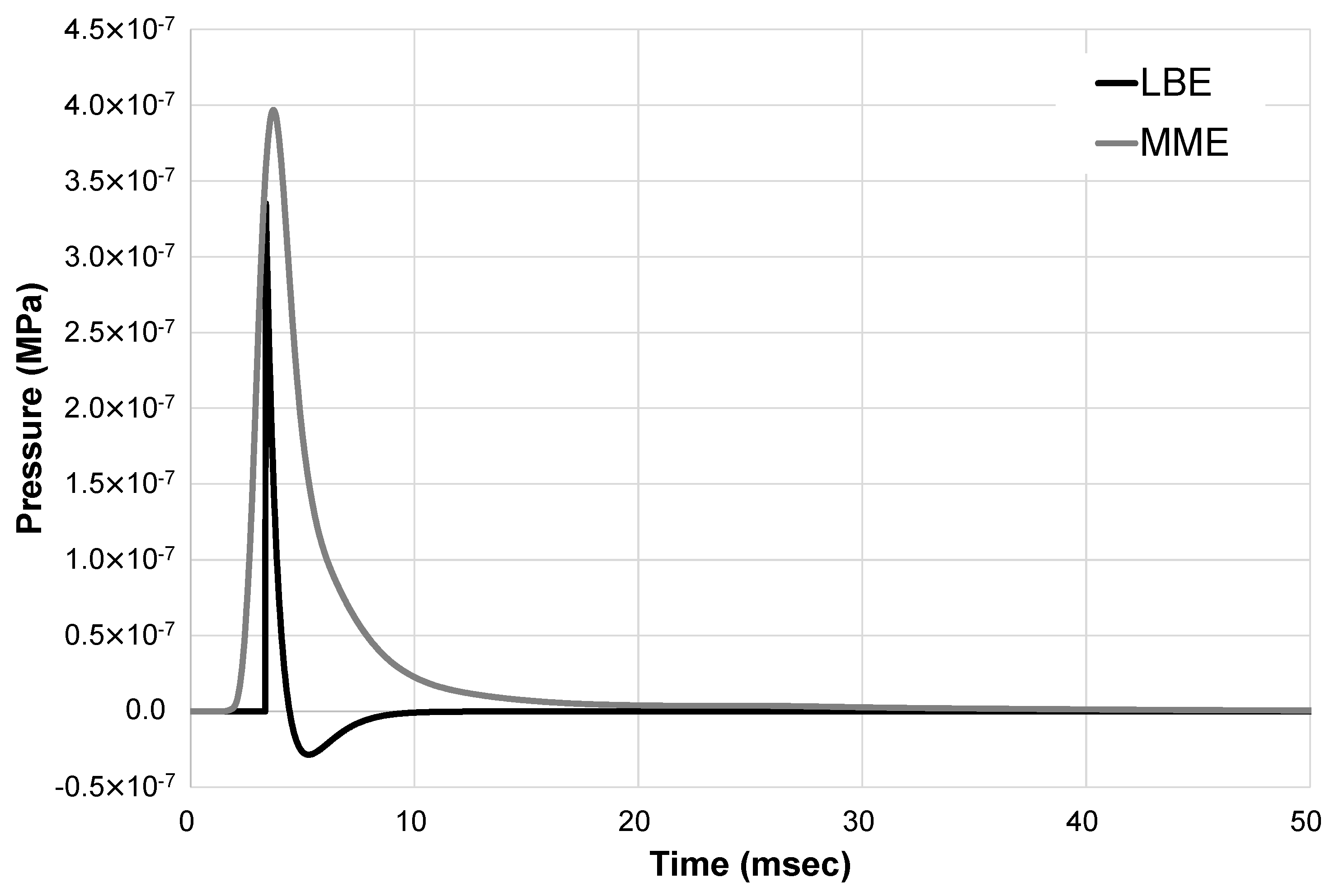
In this study, a preliminary analysis was performed to select the analysis method between multi-material arbitrary Lagrangian–Eulerian (MME) and load-blast enhanced (LBE). The concrete walls, which have the same characteristics as the main analysis including materials and element size, were analyzed. As in the main analysis, 4 kg of TNT was placed at a vertical distance of 300 mm from the center of the structure surface. The surfaces for LBE were defined as the front of a wall that was directly affected by the explosion. Table 1 and Figure 3 show the analysis results from both methods of MME and LBE. The maximum pressures of MME and LBE were 3.97 × 10⁻⁷ MPa and 3.33 × 10⁻⁷ MPa, respectively. The area of the pressure curve of MME was larger than that of LBE, as shown in Figure 3. For the LBE method, the explosive pressure was directly applied to the element surfaces. For the MME, however, since the explosion load at the origin was transmitted through the atmosphere elements, the residual pressure was transmitted through the atmosphere after the maximum explosion pressure. Therefore, as shown in Figure 3, the pressure curve area of the MME was larger than the pressure curve area of the LBE, although the maximum pressure did not show a large difference. Table 1 compared the duration time of both analysis methods. The LBE method could be regarded as a more efficient explosion analysis method since the analysis time of MME was about 90 times longer than that of LBE. As a result, it is considered that the MME method is suitable for understanding the flow and progress of the explosive pressure, and the LBE method is suitable for understanding the effect of the maximum pressure on the structure under the explosive load. Therefore, in this study, the LBE method was chosen considering that the maximum pressure is similar to MME and it is more efficient in terms of analysis time. Moreover, many research studies showed that the LBE method is more efficient than the MME method considering analysis results and time [59,60,61].
Based on empirical formulas of blast loads, the Protective Design Center (PDC) of US ARMY releases the Conventional Weapons Effects (ConWep), which could perform a variety of conventional weapons effects from TM 5-855-1 [58,62]. The LS-DYNA applies the ConWep system to LBE. The blast loads of TNTs were located 300 mm from the column and slab. The variables for the amount of TNT were 4 kg and 12 kg. The mass of TNT used in this analysis represents the small and large briefcase bomb, as shown in Table 2 [63]. When 4 kg of TNT was used, which is equal to the amount used in a small briefcase, the blast resistance behavior could be well observed because the slab was not completely destroyed. On the other hand, when 12 kg of TNT was used, which is equal to the amount used in a large briefcase, a significant portion of the slab where the explosive load was placed was destroyed. Table 3 summarized the descriptions of the specimens including blast loads.

4. Analysis Results

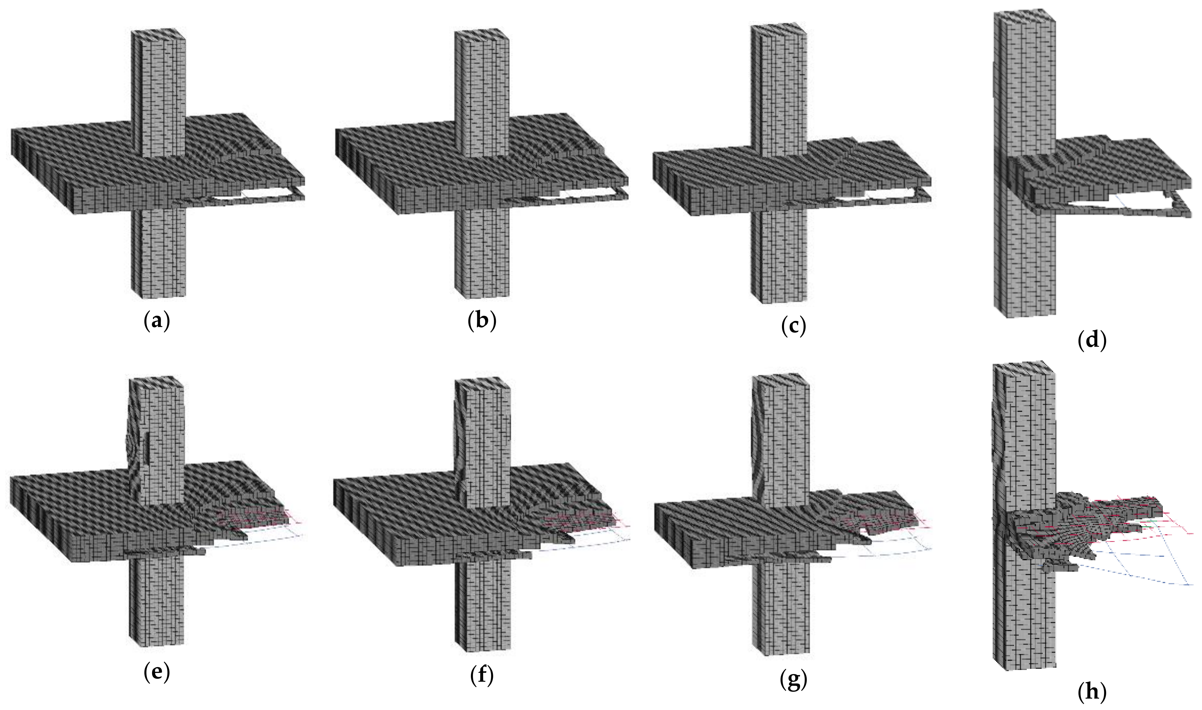
From the analysis results, typical forms of pressure distribution were commonly observed in every specimen, as shown in Figure 4. When the explosive load was applied, high compressive forces were generated in the slabs and columns directly affected by the explosion load. Then, the overpressure spread spherically through the slab–column connection. The analysis end time was set to 3000 ms, which is the time at which deformation of all specimens was found stable. As shown in Figure 5a–d, for specimens subjected to 4 kg of TNT, spalling on the rear face of the slab, was severer than that on the front face. These phenomena of pressure development and spalling are quite similar to previous researches [33,43,53]. Looking at the fracture pattern of the specimen under 12 kg of TNT, the part of the slab where the explosion load was placed was completely lost, as shown in Figure 5e–h.

4.1. Slab Deflection

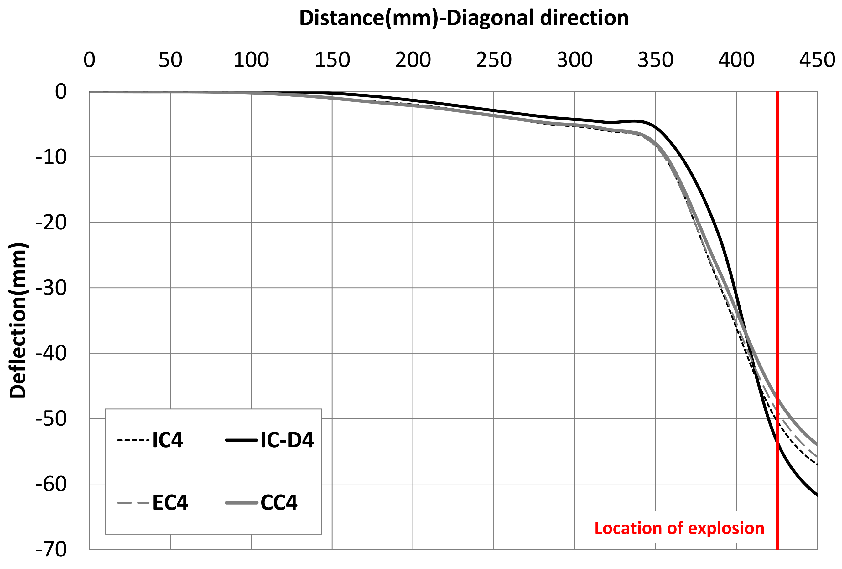
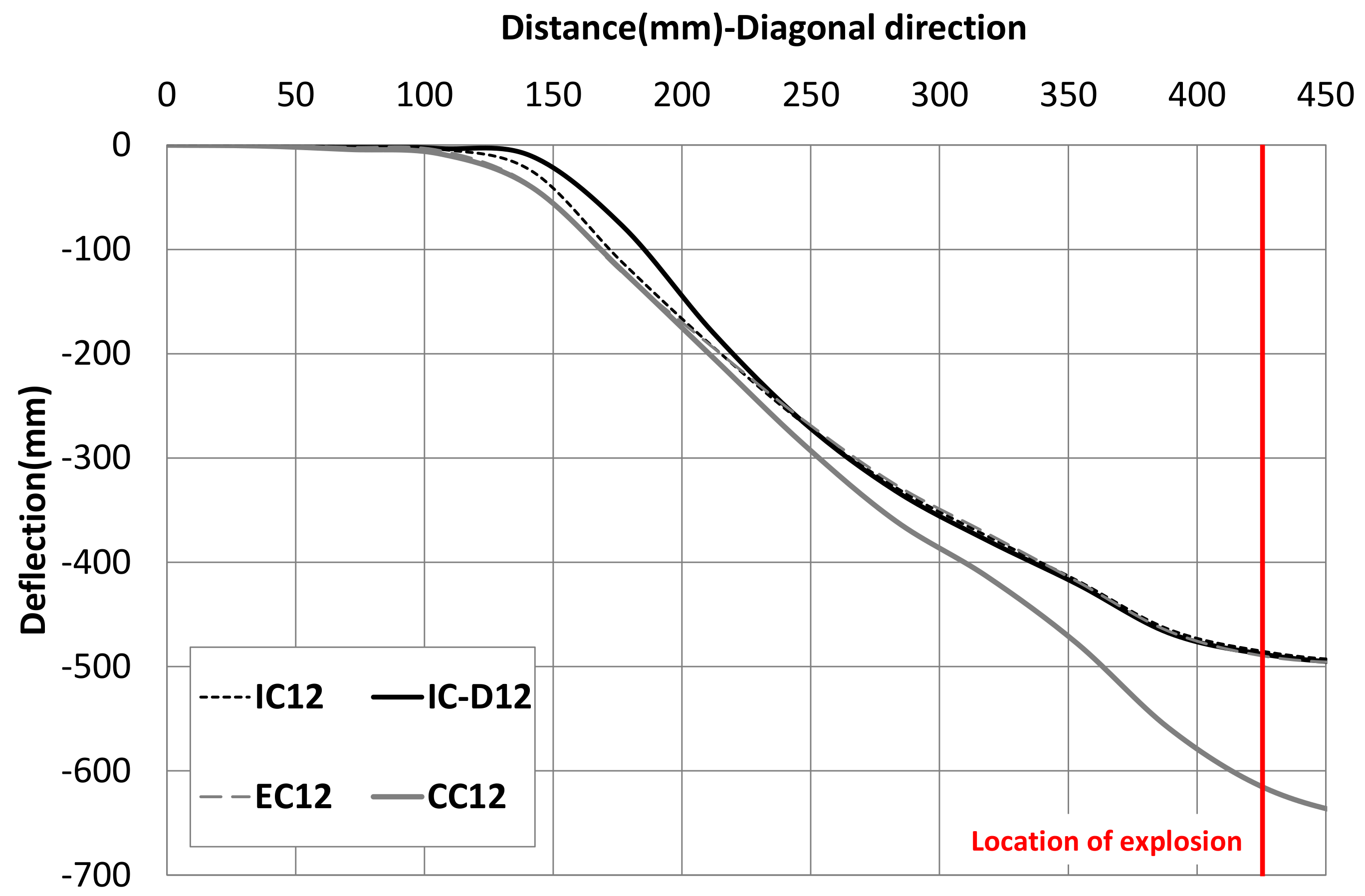
Figure 6 shows the deflection of the slab subjected to TNT 4 kg along the diagonal distance away from the corner of the column. The maximum deflections of the slab occurred similarly in every specimen with TNT 4 kg. The deflection of the slab increased rapidly from the point about 350 mm away from the corner of the column. This point is similar to the point where the fracture of the slab occurred. Figure 7 shows the slab deflections for TNT 12 kg. Large deflections were observed at about 150 mm away from the corner of the column, and beyond that point, fracture of the slab was observed. As the larger explosive load was applied, the fracture area was much larger than that of 4 kg TNT applied specimens.
When comparing the effective deflection of the unbroken part of the slab, it was confirmed that the drop panel slightly reduced deflection. However, for all specimens with TNT of 4 kg and 12 kg, comparing the specimens IC, EC, and CC, the slab deflection according to the position of the column showed no significant difference.

4.2. Critical Section in Slab

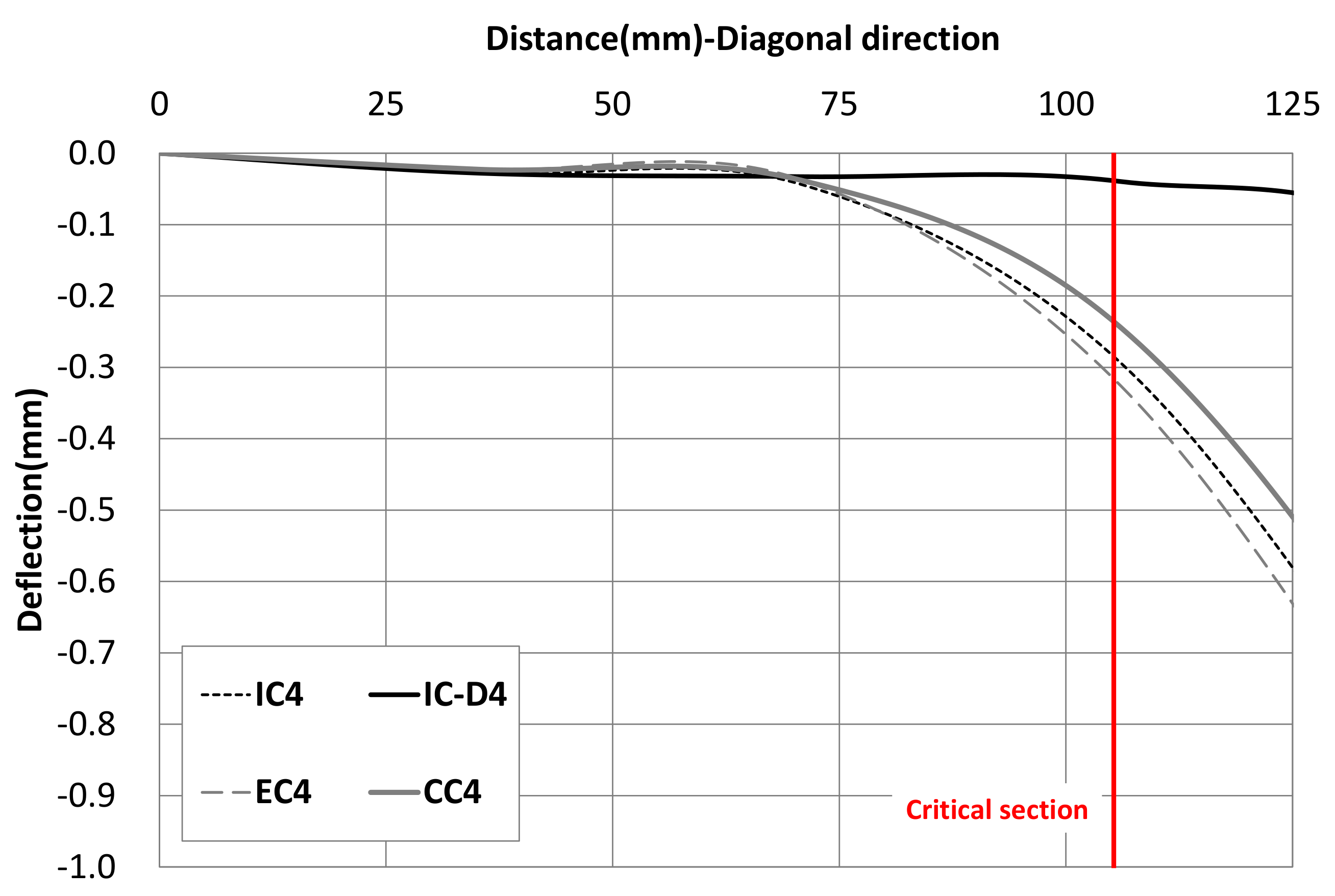
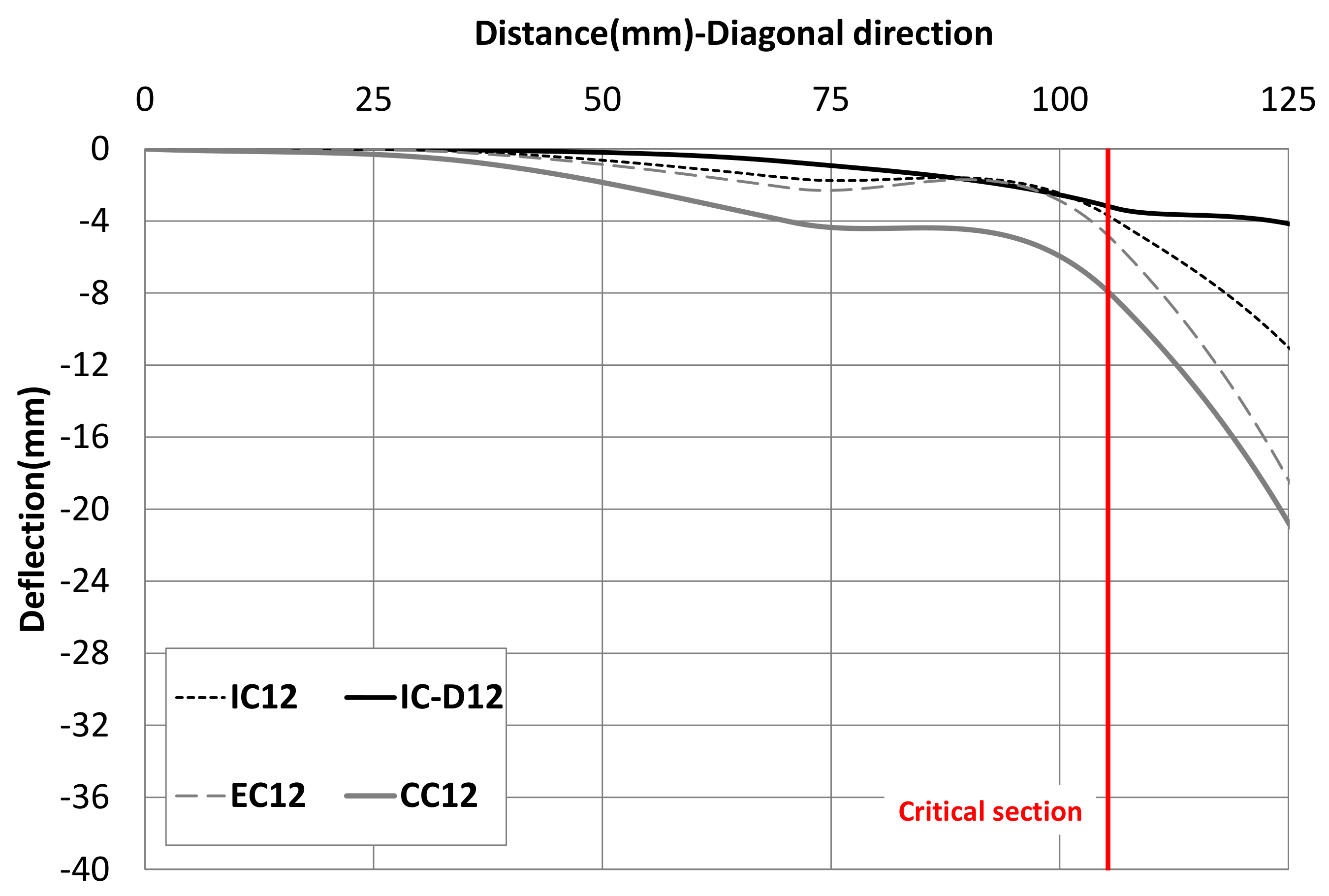
In slab–column connections, a section that is 1/2 of the effective depth, d, from the outer surface of the column is regarded as a critical section [45]. Sufficient safety must be ensured for critical sections to prevent the collapse of the entire structure due to large damage of the joints [44,64]. Figure 8 shows failure shapes of slabs for specimens subjected to 12 kg of TNT. For specimens EC and CC, spalling due to the blast load occurred over the critical section, but specimens IC and IC-D showed a more positive structural behavior in which spalling did not spread to the critical section. Table 4 shows the deformation and support rotation at the critical section for all specimens. The deformations in the critical section of the specimens IC-D4 and IC-D12 were 0.040 mm and 3.284 mm, which were the least deformations among the specimens subjected to the same blast load. Figure 9 and Figure 10 show the deflections in the critical section. In Figure 9, the specimens, except for specimen IC-D4, show similar behavior. The inflection points of deflection curves occurred within the critical sections for all specimens except the specimens reinforced with drop panels. In other words, the safety of the critical section was enhanced by the drop panel. Therefore, the drop panel can be considered as a method to effectively resist blast loads.
According to the criteria, the limit of support rotation to effectively resist the moment is two degrees [41,43]. However, according to the analysis results, it was found that this evaluation criterion alone was insufficient to adequately represent the blast-resistant performance of the member. This is because the support rotation in the critical section of all specimens was below the criteria limit of two degrees, but in reality, most specimens showed that the slab was destroyed. Therefore, in order to more accurately and reasonably evaluate blast-resistant performance, it is necessary to consider various evaluation factors in addition to support rotation.

4.3. Steel Stresses in Slab

The peak stresses in the reinforcement of the slab are shown in Table 5. In every specimen with TNT 4 kg and 12 kg, the peak rebar stress occurred near the explosive load. Although a large fracture occurred in the slab, the peak stresses of all reinforcing bars did not reach the maximum strength to which dynamic increased factor was applied. This phenomenon is believed to occur because the concrete is destroyed by the explosive energy at a moment and the energy is not sufficiently transmitted to the reinforcing bar. However, in the previous study, it has been confirmed that the reinforcing bars affect the blast-resistance capacities in the beam–column connections [65].
For most specimens, the stresses of bottom reinforcements of the slab were larger than those of top slab reinforcements. This phenomenon is due to the failure mode in which the rear fracture was more severe than the fracture of the front face to which the explosive load was applied. The effect of the drop panel on the reinforcement stress was not clearly observed, considering that the slab reinforcement stresses of IC and IC-D were similar.

4.4. Column Behavior

Table 6 shows the maximum horizontal deformation of columns. When comparing column behaviors of specimens IC and IC-D, the drop panel was found to be effective in controlling the horizontal displacement of columns under explosive load. Comparing CC, EC, and IC specimens, the larger the constraint of the column by the surrounding slab was, the less horizontal displacement of the column was observed. In the case of CC12, a very large displacement occurred at the end of the analysis, and the column of specimen CC12 seems to have been destroyed as displacement shows a continuous trend of increase. Therefore, it is necessary to pay special attention to the blast-resistance performance for the relatively large explosive load in the case of a corner column having a low constraint by a surrounding slab.

5. Conclusions

The blast resistance of slab–column connection was numerically analyzed. The confinement effect of connection on the blast resistance was investigated through a comparison of the slab-interior column, slab-edge column, and slab-corner column. In addition, the effect of the drop panel on the blast resistance performance was investigated. The conclusions from this numerical study are as follows:
(1)
Analysis results showed that the slab-interior column had a better performance than the slab-edge column and slab-corner column in terms of slab failure at critical section and column deformation. The confinement effect seems to be considered in the design of blast-resistant structures. However, the effect of the position of the column on the behavior of the slab such as slab deflection and support rotation under explosive load was not apparent. Further research is needed with the location of the explosive load and the dimensions of columns and slabs as variables.
(2)
The drop panel was observed to contribute to the improvement of the blast-resistance performance. For 4 kg and 12 kg of TNT, the drop panel reduced the maximum deflection of the slab at the critical section by approximately 86% and 17%, and the column deformation by approximately 2.9% and 4.8%, respectively.
(3)
Although significant concrete fracture occurred in the slab, the maximum stress of the reinforcing bar did not reach the tensile strength. This phenomenon occurs because the concrete is momentarily destroyed by the explosive energy and the energy is not sufficiently transmitted to the reinforcing bars. Further research is needed to ensure that the blast energy can be sufficiently transmitted to the rebar through the concrete.
(4)
For most design criteria, the support rotation has been considered as a major criterion for blast-resistant capacities. It is a very simple and good evaluation factor representing the critical behavior of the joint. However, in this study, considerable failure occurred in the slab member even though the support rotations at the critical section were satisfied with the criteria. Therefore, for a more accurate evaluation of blast resistance performance, various evaluation factors such as ductility ratio, reinforcing stress, and concrete fracture area can be considered along with the support rotation.

Author Contributions

Conceptualization, K.M.L. and J.H.L.; data analysis and writing—original draft preparation, K.M.L.; writing—review and editing, K.M.L., T.H.H. and J.H.L.; supervision, T.H.H. and J.H.L. All authors have read and agreed to the published version of the manuscript.

Funding

This research was supported by a grant (21CTAP-C152069-03) from the Technology Advancement Research Program funded by the Ministry of Land, Infrastructure, and Transport of the Korean government.

Acknowledgments

This paper is an extended version of the conference paper presented at the CECAR7 (2016). This research was supported by a grant (21CTAP-C152069-03) from the Technology Advancement Research Program funded by the Ministry of Land, Infrastructure, and Transport of the Korean government.

Conflicts of Interest

The authors declare no conflict of interest.

References

  1. Brun, M.; Batti, A.; Limam, A.; Gravouil, A. Explicit/implicit multi-time step co-computations for blast analyses on a reinforced concrete frame structure. Finite Elem. Anal. Des. 2012, 52, 41–59. [Google Scholar] [CrossRef]
  2. Hajek, R.; Fladr, J.; Pachman, J.; Stoller, J.; Foglar, M. An experimental evaluation of the blast resistance of heterogeneous concrete-based composite bridge decks. Eng. Struct. 2018, 179, 204–210. [Google Scholar] [CrossRef]
  3. Kumar, V.; Kartik, K.; Iqbal, M. Experimental and numerical investigation of reinforced concrete slabs under blast loading. Eng. Struct. 2020, 206, 110125. [Google Scholar] [CrossRef]
  4. Abdulsamee, M.H.; Yazan, B.A.T.; Amin, H.A.; George, Z.V. The effect of shape memory alloys on the ductility of exterior reinforced concrete beam-column joints using the damage plasticity model. Eng. Struct. 2019, 200, 109676. [Google Scholar]
  5. Cumhur, C.; Ahmet, M.T.; Atakan, M.; Turgay, C.; Guven, K. Experimental behavior and failure of beam-column joints with plain bars, low-strength concrete and different anchorage details. Eng. Fail. Anal. 2020, 109, 104247. [Google Scholar]
  6. Yim, H.C.; Krauthammer, T. Load-impulse characterization for steel connections in monolithic reinforced concrete structures. Int. J. Impact Eng. 2009, 36, 737–745. [Google Scholar] [CrossRef]
  7. Andrew, R.; Nicola, B.; Giuseppe, C.; Stefano, D.M.; Gianluca, I.; Sonia, M.; Elio, S.; Sara, S.; Gabriel, T. Full scale experimental tests and numerical model validation of reinforced concrete slab subjected to direct contact explosion. Int. J. Impact Eng. 2019, 132, 103309. [Google Scholar]
  8. Azer, M.; Stijn, M.; Bachir, B.; David, L.; John, V. Blast response of retrofitted reinforced concrete hollow core slabs under a close distance explosion. Eng. Struct. 2019, 191, 447–459. [Google Scholar]
  9. Bianchini, A.C.; Woods, R.E.; Kesler, C.E. Effect of floor concrete strength on column strength. ACI J. Proc. 1960, 56, 1149–1170. [Google Scholar]
  10. McHarg, P.J.; Cook, W.D.; Mitchell, D.; Yoon, Y.S. Benefits of concentrated slab reinforcement and steel fibers on performance of slab-column connections. ACI Struct. J. 2000, 97, 225–234. [Google Scholar]
  11. Lee, J.-H.; Yoon, Y.-S.; Cook, W.D.; Mitchell, D. Benefits of Using Puddled HSC with Fibers in Slabs to Transmit HSC Column Loads. J. Struct. Eng. 2007, 133, 1843–1847. [Google Scholar] [CrossRef]
  12. Morrison, D.G.; Hirasawa, I.; Sozen, M.A. Lateral-load tests of R/C slab-column connections. J. Struct. Eng. 1983, 109, 2698–2714. [Google Scholar] [CrossRef]
  13. Marzouk, H.; Osman, M.; Hussein, A. Cyclic Loading of High-Strength Lightweight Concrete Slabs. ACI Struct. J. 2001, 98, 207–214. [Google Scholar]
  14. Tian, Y.; Jirsa, J.O.; Bayrak, O.; Widianto; Argudo, J.F. Behavior of Slab-Column Connections of Existing Flat-Plate Structures. ACI Struct. J. 2008, 105, 561. [Google Scholar] [CrossRef]
  15. Drakatos, I.-S.; Muttoni, A.; Beyer, K. Internal slab-column connections under monotonic and cyclic imposed rotations. Eng. Struct. 2016, 123, 501–516. [Google Scholar] [CrossRef] [Green Version]
  16. Isufi, B.; Rossi, M.; Ramos, A.P. Influence of flexural reinforcement on the seismic performance of flat slab–column connections. Eng. Struct. 2021, 242, 112583. [Google Scholar] [CrossRef]
  17. Emam, M.; Marzouk, H.; Hilal, M.S. Seismic response of slab-column connections constructed with high-strength concrete. ACI Struct. J. 1997, 94, 197–205. [Google Scholar]
  18. Marzouk, H.; Emam, M.; Hilal, M.S. Effect of high-strength concrete slab on the behavior of slab-column connections. ACI Struct. J. 1998, 95, 227–237. [Google Scholar]
  19. Inácio, M.; Isufi, B.; Lapi, M.; Ramos, A.P. Rational use of high-strength concrete in flat slab-column connections under seismic loading. ACI Struct. J. 2020, 117, 297–310. [Google Scholar] [CrossRef]
  20. Smadi, M.; Yasin, I.B. Behavior of high-strength fibrous concrete slab–column connections under gravity and lateral loads. Constr. Build. Mater. 2008, 22, 1863–1873. [Google Scholar] [CrossRef]
  21. Scotta, R.; Giorgi, P. Comparative cyclic tests of exterior flat slab–column connections in normal concrete and fiber-reinforced lightweight aggregate concrete. Mater. Struct. 2015, 49, 4049–4067. [Google Scholar] [CrossRef]
  22. Buitrago, M.; Bertolesi, E.; Sagaseta, J.; Calderón, P.A.; Adam, J.M. Robustness of RC building structures with infill masonry walls: Tests on a purpose-built structure. Eng. Struct. 2020, 226, 111384. [Google Scholar] [CrossRef]
  23. Adam, J.M.; Buitrago, M.; Bertolesi, E.; Sagaseta, J.; Moragues, J.J. Dynamic performance of a real-scale reinforced concrete building test under a corner-column failure scenario. Eng. Struct. 2020, 210, 110414. [Google Scholar] [CrossRef]
  24. Mousapoor, E.; Ghiasi, V.; Madandoust, R. Macro modeling of slab-column connections in progressive collapse with post-punching effect. In Structures; Elsevier: Amsterdam, The Netherlands, 2020. [Google Scholar] [CrossRef]
  25. Yankelevsky, D.; Karinski, Y.; Feldgun, V. Dynamic punching shear failure of a RC flat slab-column connection under a collapsing slab impact. Int. J. Impact Eng. 2019, 135, 103401. [Google Scholar] [CrossRef]
  26. Adam, J.M.; Parisi, F.; Sagaseta, J.; Lu, X. Research and practice on progressive collapse and robustness of building structures in the 21st century. Eng. Struct. 2018, 173, 122–149. [Google Scholar] [CrossRef]
  27. Setiawan, A.; Vollum, R.L.; Macorini, L. Numerical and analytical investigation of internal slab-column connections subject to cyclic loading. Eng. Struct. 2019, 184, 535–554. [Google Scholar] [CrossRef]
  28. Silva, F.P.; Lu, B. Improving the blast resistance capacity of RC slabs with innovative composite materials. Compos. Part B Eng. 2007, 38, 523–534. [Google Scholar] [CrossRef]
  29. Schenker, A.; Anteby, I.; Gal, E.; Kivity, Y.; Nizri, E.; Sadot, O.; Michaelis, R.; Levintant, O.; Ben-Dor, G. Full-scale field tests of concrete slabs subjected to blast loads. Int. J. Impact Eng. 2008, 35, 184–198. [Google Scholar] [CrossRef]
  30. Wu, C.; Oehlers, D.; Rebentrost, M.; Leach, J.; Whittaker, A. Blast testing of ultra-high performance fibre and FRP-retrofitted concrete slabs. Eng. Struct. 2009, 31, 2060–2069. [Google Scholar] [CrossRef]
  31. Alonso, M.G.; Cendon, A.D.; Galvez, F.; Erice, B.; Galvez, S.V. Blast response analysis of reinforced concrete slabs: Experimental procedure and numerical simulation. J. Appl. Mech. 2011, 78, 1–12. [Google Scholar]
  32. Wang, W.; Zhang, D.; Lu, F.; Wang, S.-C.; Tang, F. Experimental study and numerical simulation of the damage mode of a square reinforced concrete slab under close-in explosion. Eng. Fail. Anal. 2012, 27, 41–51. [Google Scholar] [CrossRef]
  33. Thiagarajan, G.; Kadambi, V.A.; Robert, S.; Johnson, F.C. Experimental and finite element analysis of doubly reinforced concrete slabs subjected to blast loads. Int. J. Impact Eng. 2015, 75, 162–173. [Google Scholar] [CrossRef]
  34. Li, J.; Wu, C.; Hao, H. Investigation of ultra-high performance concrete slab and normal strength concrete slab under contact explosion. Eng. Struct. 2015, 102, 395–408. [Google Scholar] [CrossRef]
  35. Castedo, R.; Segarra, P.; Alanon, A.; Lopez, M.L.; Santos, P.A.; Sanchidrian, A.J. Air blast resistance of full-scale slabs with different compositions: Numerical modeling and field validation. Int. J. Impact Eng. 2015, 86, 145–156. [Google Scholar] [CrossRef]
  36. Yao, S.; Zhang, D.; Chen, X.; Lu, F.; Wang, W. Experimental and numerical study on the dynamic response of RC slabs under blast loading. Eng. Fail. Anal. 2016, 66, 120–129. [Google Scholar] [CrossRef]
  37. Zhou, Q.X.; Kuznetsov, A.V.; Hao, H.; Waschl, J. Numerical prediction of concrete slab response to blast loading. Int. J. Impact Eng. 2008, 35, 1186–1200. [Google Scholar] [CrossRef]
  38. Shahriari, A.; Birzhandi, M.S.; Zafarani, M.M. Seismic behavior, blast response and progressive collapse of RC structures equipped with viscoelastic dampers. Soil Dyn. Earthq. Eng. 2021, 143, 106643. [Google Scholar] [CrossRef]
  39. Krauthammer, T. Blast-resistant structural concrete and steel connections. Int. J. Impact Eng. 1999, 22, 887–910. [Google Scholar] [CrossRef]
  40. Lim, K.M.; Yoon, Y.S.; Lee, J.H. Numerical analysis on dynamic behavior of slab-column connections subjected to blast loads. In Proceedings of the 7th Civil Engineering Conference in the Asian Region (CECAR 7), Waikiki, HI, USA, 30 August–2 September 2016. [Google Scholar]
  41. ASCE/SEI (American Society of Civil Engineers/Structural Engineering Institute). ASCE/SEI 59-11: Blast Protection of Building; ASCE: Reston, VA, USA, 2011. [Google Scholar]
  42. Pereira, J.M.; Dias, A.; Lourenco, P.B. Dynamic properties of clay brick at different stain rates. In Proceedings of the 12th Canadian Masonry Symposium, Vancouver, BC, Canada, 2–5 June 2013. [Google Scholar]
  43. Department of Defense. UFC 3-340-02: Structures to Resist the Effects of Accidental Explosions; Department of Defense: Arlington, VA, USA, 2008.
  44. ACI (American Concrete Institute) Committee 318. ACI318-11: Building Code Requirements for Structural Concrete & Commentary; American Concrete Institute: Farmington Hills, MI, USA, 2011. [Google Scholar]
  45. ACI-ASCE (American Concrete Institute-American Society of Civil Engineers) Committee 352. ACI352.1R-11: Guide for Design of Slab-Column Connections in Monolithic Concrete Structures; American Concrete Institute: Farmington Hills, MI, USA, 2012. [Google Scholar]
  46. Gamble, W.L.; Klinar, J.D. Tests of High?Strength Concrete Columns with Intervening Floor Slabs. J. Struct. Eng. 1991, 117, 1462–1476. [Google Scholar] [CrossRef]
  47. Brannon, R.M.; Leelavanichkul, S. Survey of Four Damage Models for Concrete; SAND2009-5544; Sandia National Laboratories: Albuquerque, NM, USA, 2009. [Google Scholar]
  48. Crawford, J.E.; Wu, Y.; Choi, H.J.; Magallanes, J.M.; Lan, S. Use and Validation of the Release III K&C Concrete Material Model in LS-DYNA; Karagozian & Case Technical Report TR-11-36.5; Karagozian & Case, Inc.: Glendale, CA, USA, 2012. [Google Scholar]
  49. LSTC (Livermore Software Technology Corporation). LS-DYNA Keyword User’s Manual Volume II Material Models; Livermore Software Technology Corporation: Livermore, CA, USA, 2013. [Google Scholar]
  50. Ling, L. Local Damages and Blast Resistance of RC Slabs Subjected to Contact Detonation. Master’s Thesis, Korea University, Seoul, Korea, 2013. [Google Scholar]
  51. Gonzalez, H.A.; Zapatero, J. Influence of minimum element size to determine crack closure stress by the finite element method. Eng. Fract. Mech. 2005, 72, 337–355. [Google Scholar] [CrossRef]
  52. Krauthammer, T.; Otani, R. Mesh, gravity and load effects on finite element simulations of blast loaded reinforced concrete structures. Comput. Struct. 1997, 63, 1113–1120. [Google Scholar] [CrossRef]
  53. Foglar, M.; Kovar, M. Conclusions from experimental testing of blast resistance of FRC and RC bridge decks. Int. J. Impact Eng. 2013, 59, 18–28. [Google Scholar] [CrossRef]
  54. Shi, Y.; Stewart, M.G. Damage and risk assessment for reinforced concrete wall pannels subjected to explosive blast loading. Int. J. Impact Eng. 2015, 85, 5–19. [Google Scholar] [CrossRef]
  55. Guang, Z.; Hong, N.; Jinbao, C.; Chuanzhi, C.; Heow, P.L. Dynamic analysis of lunar lander during soft landing using explicit finite element method. Acta Astronaut. 2018, 148, 69–81. [Google Scholar]
  56. Kang, J.J.; Oh, S.I. Hourglass control in rigid-plastic finite element analysis. Korean Soc. Mech. Eng. 1996, 20, 1290–1300. [Google Scholar]
  57. Kim, K.S.; Cho, J.U.; Choi, D.S. An analysis of plastic stress in square bar impacting plat. Trans. Korean Soc. Automot. Eng. 2004, 12, 198–204. [Google Scholar]
  58. LSTC (Livermore Software Technology Corporation). LS-DYNA Keyword User’s Manual Volume I; Livermore Software Technology Corporation: Livermore, CA, USA, 2013. [Google Scholar]
  59. Bae, D.-M.; Zakki, A. Comparisons of Multi Material ALE and Single Material ALE in LS-DYNA for Estimation of Acceleration Response of Free-fall Lifeboat. J. Soc. Nav. Arch. Korea 2011, 48, 552–559. [Google Scholar] [CrossRef] [Green Version]
  60. Jang, I.H. Sloshing Response Analysis of LNG Carrier Tank Using Fluid Structure Interaction Analysis Technique of LS-DYNA3D. Master’s Thesis, Korea Maritime and Ocean University, Busan, Korea, 2007. [Google Scholar]
  61. Zahra, S.T.; Jeffery, S.V. A comparison between three different blast methods in LS-DYNA: LBE, MM-ALE, Coupling of LBE and MM-ALE. In Proceedings of the 12th International LS-DYNA User Conference, Dearborn, MI, USA, 3–5 June 2012. [Google Scholar]
  62. Huh, Y.C.; Chung, T.Y.; Kim, K.C.; Jung, H.J.; Choi, H.H. A study on the modeling techniques of air blast load using LS-DYNA. In Proceedings of the Korean Society for Noise and Vibration Engineering Conference, Daegu, Korea, 26–27 April 2012; pp. 375–376. [Google Scholar]
  63. Yandzio, E.; Gough, M. Protection of Buildings against Explosions; The Steel Construction Institute: Ascot, UK, 1999. [Google Scholar]
  64. Krauthammer, T. Modern Protective Structures; CRC Press: Boca Raton, FL, USA, 2008. [Google Scholar]
  65. Lim, K.-M.; Shin, H.; Kim, D.-J.; Yoon, Y.-S.; Lee, J.-H. Numerical Assessment of Reinforcing Details in Beam-Column Joints on Blast Resistance. Int. J. Concr. Struct. Mater. 2016, 10, 87–96. [Google Scholar] [CrossRef] [Green Version]
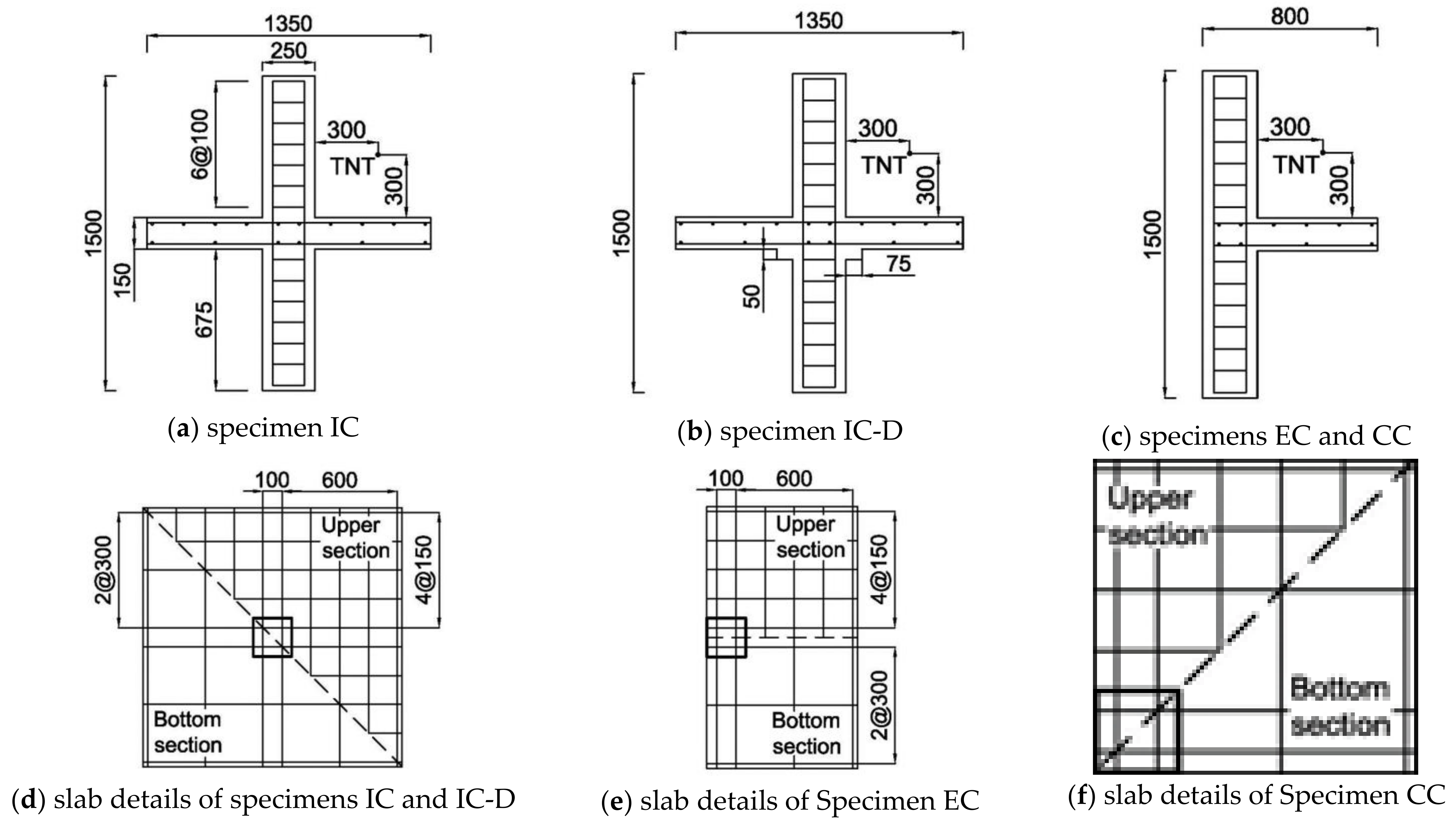
Figure 1. Details of specimens: (a) specimen IC; (b) specimen IC-D; (c) specimens EC and CC; (d) slab details of specimens IC and IC-D; (e) slab details of specimen EC; (f) slab details of specimen CC.
Applsci 11 07573 g001
Figure 2. Process of the negative volume.
Applsci 11 07573 g002
Figure 3. Comparison of pressure histories of MME and LBE.
Applsci 11 07573 g003
Figure 4. Typical forms of pressure distribution.
Applsci 11 07573 g004
Figure 5. Failure shape of slab–column connections: (a) specimen IC4; (b) specimen IC-D4; (c) specimen EC4; (d) specimen CC4; (e) specimen IC12; (f) specimen IC-D12; (g) specimen EC12; (h) specimen CC12.
Applsci 11 07573 g005
Figure 6. Slab deflection of specimens with TNT 4 kg.
Applsci 11 07573 g006
Figure 7. Slab deflection of specimens with TNT 12 kg.
Applsci 11 07573 g007
Figure 8. Critical section and slab failure shapes of specimens with TNT 12 kg: (a) IC12; (b) IC-D12; (c) EC12; (d) CC12.
Applsci 11 07573 g008
Figure 9. Slab deflection at the critical section with TNT 4 kg.
Applsci 11 07573 g009
Figure 10. Slab deflection at the critical section with TNT 12 kg.
Applsci 11 07573 g010
Table 1. Comparison of analysis time of MME and LBE.
VariablesNumber of ElementsAnalysis TimeDuration of Analysis
StructuresAirTNT
LBE800--129 s100 ms
MME8005607512511,075 s
Table 2. Typical example of terrorist explosive materials [63].
Explosion MethodMaterial TypeLoaded Weight
Small briefcaseMilitary commercial bomb such as TNT2~4 kg
Large briefcase4~12 kg
Suitcase12~22 kg
Bicycle30 kg
Table 3. Specimen descriptions.
SpecimenDescriptionCharged Weight of TNT
IC4Slab-interior—column connection4 kg
IC1212 kg
IC-D4Slab-interior—column connection
reinforcing with drop panel
4 kg
IC-D1212 kg
EC4Slab-edge—column connection4 kg
EC1212 kg
CC4Slab-corner—column connection4 kg
CC1212 kg
Table 4. Maximum deflection and support rotation at critical section.
SpecimenDeflection (mm)Support Rotation (°)
IC40.2940.159
IC-D40.0400.021
EC40.3260.176
CC40.2440.132
IC123.9411.277
IC-D123.2841.064
EC125.1901.682
CC128.2972.687
Table 5. Peak stresses in reinforcements of the slab.
SpecimenPeak Stress (MPa)
Top Reinforcing BarBottom Reinforcing Bar
IC432.40157.04
IC-D433.93164.08
EC429.52162.08
CC431.17137.43
IC12122.62298.52
IC-D12128.38279.72
EC12176.12312.99
CC12440.92440.48
Table 6. Maximum horizontal deformation of the column.
SpecimenColumn Deformation (mm)
TNT 4 kgTNT 12 kg
IC0.0340.104
IC-D0.0330.099
EC0.0350.171
CC0.03812.91
Publisher’s Note: MDPI stays neutral with regard to jurisdictional claims in published maps and institutional affiliations.