Article

Combined Attenuation Zones of Combined Layered Periodic Foundations

School of Civil Engineering, North China University of Technology, Beijing 100144, China
*
Author to whom correspondence should be addressed.
Appl. Sci. 2021, 11(15), 7114; https://doi.org/10.3390/app11157114
Submission received: 2 July 2021 / Revised: 21 July 2021 / Accepted: 28 July 2021 / Published: 31 July 2021
(This article belongs to the Special Issue Acoustic Metamaterials and Acoustic Foams: Recent Advances)

Abstract

:
Layered periodic foundations (LPFs) with identical unit cells have been proposed as a type of seismic metamaterials due to the unique dynamic characteristic of attenuation zones. However, it is difficult to design attenuation zones with both comparatively low starting frequencies and large bandwidths for traditional LPFs with identical unit cells. In this paper, combined layered periodic foundations (CLPFs) are proposed by combining two traditional LPFs with different unit cells in tandem. Combined attenuation zones of the CLPFs are identified by investigating the frequency response functions of the CLPFs. The generation mechanism of the combined attenuation zones was studied by varying the configuration of CLPFs. The results show that the combined attenuation zones are the union of attenuation zones of the two traditional LPFs. To verify the efficiency of CLPFs, the seismic responses of a four-story frame structure with CLPF are simulated. The present work is very helpful for the design of CLPFs with attenuation zones with a low starting frequency and large bandwidth.

1. Introduction

In recent years, periodic structures and phononic crystals have generated significant interest among researchers for their physical properties and potential applications in acoustic and elastic vibration isolation and mitigation [1,2]. Periodic structures possess a unique dynamic property of frequency attenuation zones (AZs) in which the elastic waves of certain frequencies cannot propagate. Inspired by the concept of AZs of periodic structures, PFs (also known as a type of seismic metamaterials) that consist of periodic unit cells have been proposed as a novel base isolation method to protect structures exposed to seismic excitations [3,4]. Seismic waves with frequencies in the AZs of PFs will be significantly reduced after propagating though the PFs [5]. Based on the dimensions of the periodicity of unit cells, PFs can be divided into LPFs [6,7], two-dimensional PFs [8,9,10,11] and three-dimensional PFs [12,13,14].
Due to the simplicity of configuration, LPFs have been receiving increasing attention in the field of seismic isolation. Bao et al. [6] studied the AZs of LPFs composed of alternating rubber and concrete layers by the transfer matrix method and assessed the effectiveness of the LPFs in seismic isolation through numerical simulations. By taking the thickness of unit cells as 0.4 m, the first AZ from 6.6 to 15.0 Hz was obtained in [6] by tuning the thickness ratio of rubber layers to concrete layers. Xiong et al. [15] extended the differential quadrature method to analyze the AZs of LPFs, and designed the first AZ from 2.6 to 4.3 Hz with the thickness of unit cells as 1 m. Xiang et al. [16] investigated the seismic responses of a steel structure with LPF by shake table tests. The results in [16] show that the LPF can significantly reduce the seismic responses of the upper structure when the main frequencies of seismic waves are in the AZs of the LPF. Shi et al. [17] proposed using discrete rubber blocks instead of rubber layers in LPF to obtain AZs with a lower starting frequency, where the first AZ from 2.2 to 15.0 Hz was obtained with the thickness of unit cells being 0.4 m. Liu et al. [18] studied the effect of initial stress caused by the self-weight of superstructures on the AZs of LPFs, and found that the starting frequencies of the AZs of LPFs are lower but their widths of them are narrower due to the compressive initial stress. Cheng et al. [19] considered the effects of material damping on the dispersion properties of damped LPFs by modeling rubber material as linear viscoelastic hysteretic material. Witarto et al. [20] and Liu et al. [21] conducted the global sensitivity analyses of the AZs of LPFs by the Monte Carlo simulation-based and the Gauss–Lobatto integration-based Sobol’ decomposition method, respectively.
The main frequency components of seismic waves span the range of 1–20 Hz [22], which requires AZs with both low starting frequencies and large bandwidths. The previous studies on LPFs mainly concentrated on those composed of identical unit cells. However, in such cases, the starting frequencies and bandwidths of AZs simultaneously decrease as the thickness of unit cells increases, and vice versa [15,16,17,18]. Thus, it is difficult to design AZs with both low starting frequencies and large bandwidths for traditional LPFs with identical unit cells. In order to solve the above problems, in the present paper, CLPFs with two traditional LPFs with different unit cells in tandem are proposed and the generation mechanism of combined attenuation zones (CAZs) is examined.
The remaining sections are organized as follows: the computational methods of dispersion curves for SH waves in traditional LPFs with identical unit cells and frequency response functions of CLPFs are given in Section 2. In Section 3, the effect of the filling ratio on AZs of traditional LPF with identical unit cells is discussed. In addition, the calculation method and generation mechanism of the CAZs of CLPFs are investigated. On the other hand, the seismic responses of a four-story frame structure with CLPF are simulated. Finally, some conclusions are drawn in Section 4.

2. Computational Methods

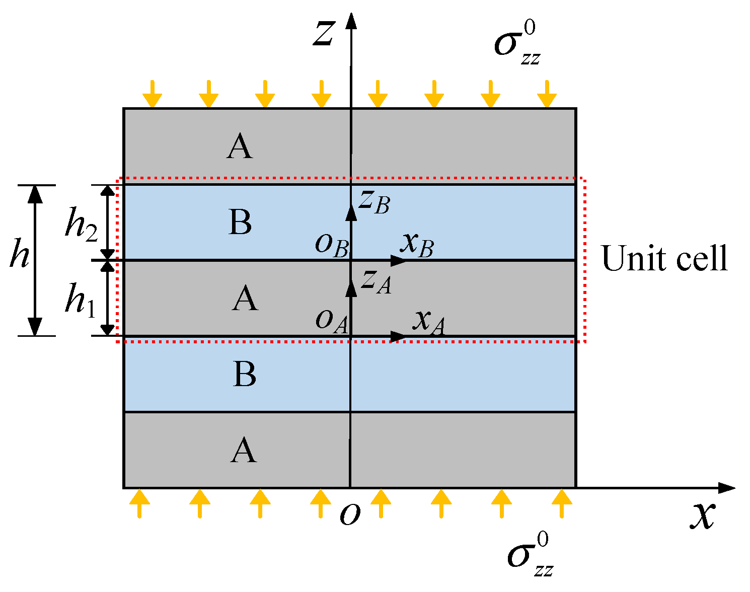
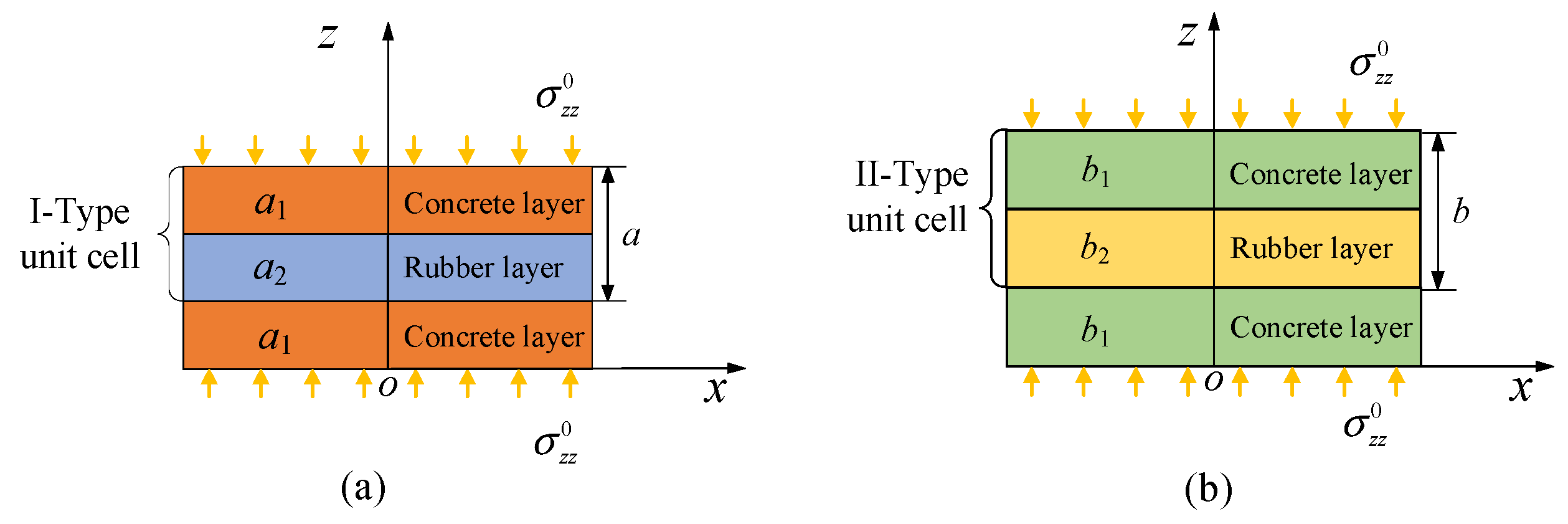
2.1. Dispersion Curves of SH Waves in Traditional LPFs with Identical Unit Cells

A traditional LPF consists of an infinite repetition of alternating concrete layer A with thickness h1 and rubber layer B with thickness h2 is schematically shown in Figure 1. The material parameters of concrete and rubber are listed in Table 1. The effect of the self-weight of the superstructure on the traditional LPF is reduced to uniformly distributed initial stress σ z z 0 . A typical unit cell whose thickness is h = h 1 + h 2 can be easily identified. Due to the spatial periodicity in the traditional LPF in Figure 1, it is sufficient to consider the dynamic characteristics of the only one typical unit cell to obtain wave propagation in the whole traditional LPF.
SH waves propagating in the z direction in the traditional and CLPF are considered in the present paper, where the displacement is in the x direction. The governing equation of SH waves in LPF can be written as [23]
( G ( e ) + σ z z 0 ) 2 u ( e ) z 2 = ρ ( e ) u ¨
where u is the displacement in the x direction; the superscript e denotes the material of layer A or B; G ( e ) and ρ ( e ) are shear modulus and mass density of the material of layer e, respectively. The solution of Equation (1) can be expressed as
u ( e ) ( z , t ) = U ( e ) ( z ) e i ω t
where ω is the angular frequency of the SH wave and U ( z ) is the displacement amplitude who is only dependent of the location in the z direction.
The connection interface of two adjacent layers is assumed to be perfectly bonded. Thus, the continuity conditions satisfy
U ( A ) ( h 1 ) = U ( B ) ( 0 ) ,   τ ( A ) ( h 1 ) = τ ( B ) ( 0 ) ,
where τ denotes the shear stress.
By using the weak form quadrature element method [24,25,26,27], the dynamic governing equations of a typical unit cell can be expressed as
[ K + K 0 ω 2 M ] d = 0
where K , K 0 , M and d are the stiffness matrix, geometric stiffness matrix due to the initial stress, and the matrix of the typical unit cell and the nodal displacement amplitude vector, respectively.
According to the Bloch–Floquet theory [5,28], the periodic boundary conditions of the unit cell can be given as
U ( A ) ( 0 ) e i k h = U ( B ) ( h 2 ) ,   τ ( A ) ( 0 ) e i k h = τ ( B ) ( h 2 ) ,
where k is the wave number.
Substituting Equation (5) into Equation (3) yields standard complex eigenvalue equations:
[ K r ( k ) + K 0 r ( k ) ω 2 ( k ) M r ] [ d i d 1 ] = [ 0 0 ]
where K r ( k ) , K 0 r ( k ) and M r are the reduced stiffness matrix, geometric stiffness matrix and mass matrix after applying the periodic boundary conditions, respectively; di is the nodal displacement amplitude vector of interior nodes of the typical unit cell and d1 is the nodal displacement amplitude of the bottom boundary, respectively. For a specific wave number k, the eigenfrequencies ω can be determined by Equation (6). Dispersion curves can be obtained by varying the wave number k in the first irreducible Brillouin zone. The gaps between two adjacent branches of the dispersion curves are the so-called AZs.

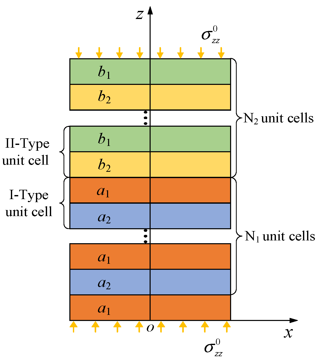
2.2. Frequency Response Functions of CLPFs

A traditional LPF with I–type unit cells and that with II–type unit cells, whose geometric parameters of unit cells are different, are used to construct CLPF, as shown in Figure 2, where a1 and a2 represent the thicknesses of the concrete and rubber layers of the Ι–type unit cells, respectively; b1 and b2 represent those of the ΙΙ–type unit cells, respectively. The CLPF consists of a layer of concrete pad, N1 I–type unit cells and N2 II–type unit cells, as shown in Figure 3, where the periodic boundary conditions are unapplicable since unit cells in the CLPF are not identical.
For simplicity, the top boundary of the CLPF is assumed to be stress free. A harmonic displacement excitation Ψ = δ e i ω t is applied to the bottom boundary of the CLPF, where δ is the amplitude of the excitation. By using the weak form quadrature element method, dynamic governing equations of the CLPF can be written as
[ K ¯ + K ¯ 0 ω 2 M ¯ ] [ d ¯ 2 d ¯ i δ ] = [ 0 0 F ¯ 1 ]
where K ¯ , K ¯ 0 and M ¯ are the stiffness matrix, geometric stiffness matrix and mass matrix of the CLPF, respectively; d ¯ i is the nodal displacement amplitude vector of interior nodes of the CLPF and d ¯ 2 is the nodal displacement amplitude of top boundary, respectively; F 1 ¯ is the nodal load force amplitude of bottom boundary of the CLPF. d i , d ¯ 2 and F ¯ 1 can be obtained from Equation (7) for specified excitation angular frequency ω and excitation amplitude δ .
To quantify the wave attenuation in the CLPF, the frequency response function (FRF) of the CLPF can be defined as
FRF = 20 log 10 | d ¯ 2 δ |
Negative FRF means that the displacement amplitude of the top boundary of the CLPF is less than the excitation displacement amplitude. For a traditional LPF with identical unit cells, results in previous studies showed that frequency ranges corresponding to the negative FRFs match well with the AZs [16,17]. In Section 3.2, the FRFs of CLPFs will be calculated to identify CAZs since the CAZs cannot be directly obtained by applying periodic boundary conditions.

3. Results and Discussion

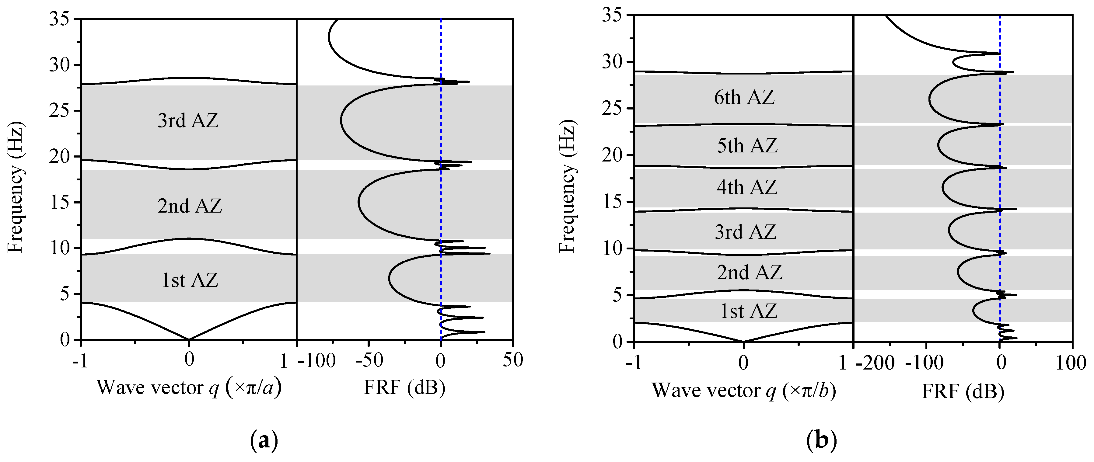
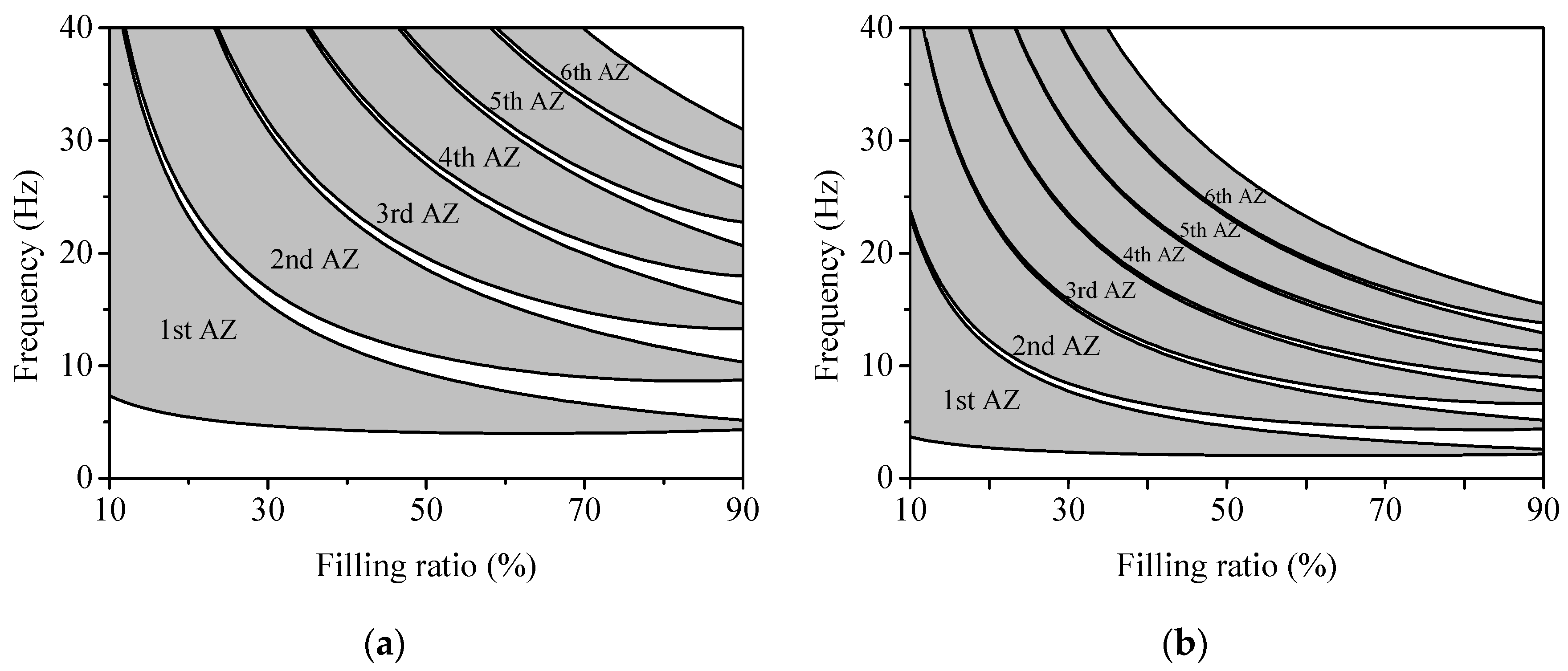
3.1. Attenuation Zones of Traditional LPFs with Identical Unit Cells

According to the findings of previous studies, the starting frequency and bandwidth of attenuation zones decrease with the increase in initial stress [18]. Thus, in engineering, the initial stress needs to be controlled in a reasonable range. In the cases discussed later, the initial stress due to the self-weight of a superstructure is taken as σ z z 0 = 0.4 G R , where G R is the shear modulus of rubber material. Here, the filling ratio of the rubber layer fr is defined as the ratio of the thickness of the rubble layer to that of the unit cell.
By using the computational methods in Section 2, the AZs and FRFs of traditional LPFs with Ι–type and ΙΙ–type unit cells with f r = 50 % can be obtained, as shown in Figure 4, where the thicknesses of unit cells are taken as a = 0.5 m and b = 1 m. It can be easily found from Figure 4 that the frequency ranges where the values of FRF are negative match well with the corresponding AZs. Moreover, by comparing the AZs in Figure 4a,b, it can be seen that the AZs of the traditional LPF with thicker unit cells are lower and narrower, which demonstrates that it is difficult to achieve both comparatively low and wide AZs of traditional LPFs with identical unit cells by tuning the thickness of unit cells.
Figure 5 shows the AZs of the traditional LPFs with Ι–type and ΙΙ–type unit cells changing with the filling ratio of rubber material, which is confined from 10 to 90%. It can be found from Figure 5 that the AZs of traditional LPFs with Ι–type and ΙΙ–type unit cells are getting narrower and the gaps between adjacent AZs wider as the filling ratio of rubber material increases to 90%. This is because that the dynamic property of traditional LPF is approaching that of homogeneous rubber material when the filling ratio of rubber material is sufficiently large and approaching 100%. It should be noted that similar cases can also be found as the filling ratio of rubber material approaches 0.

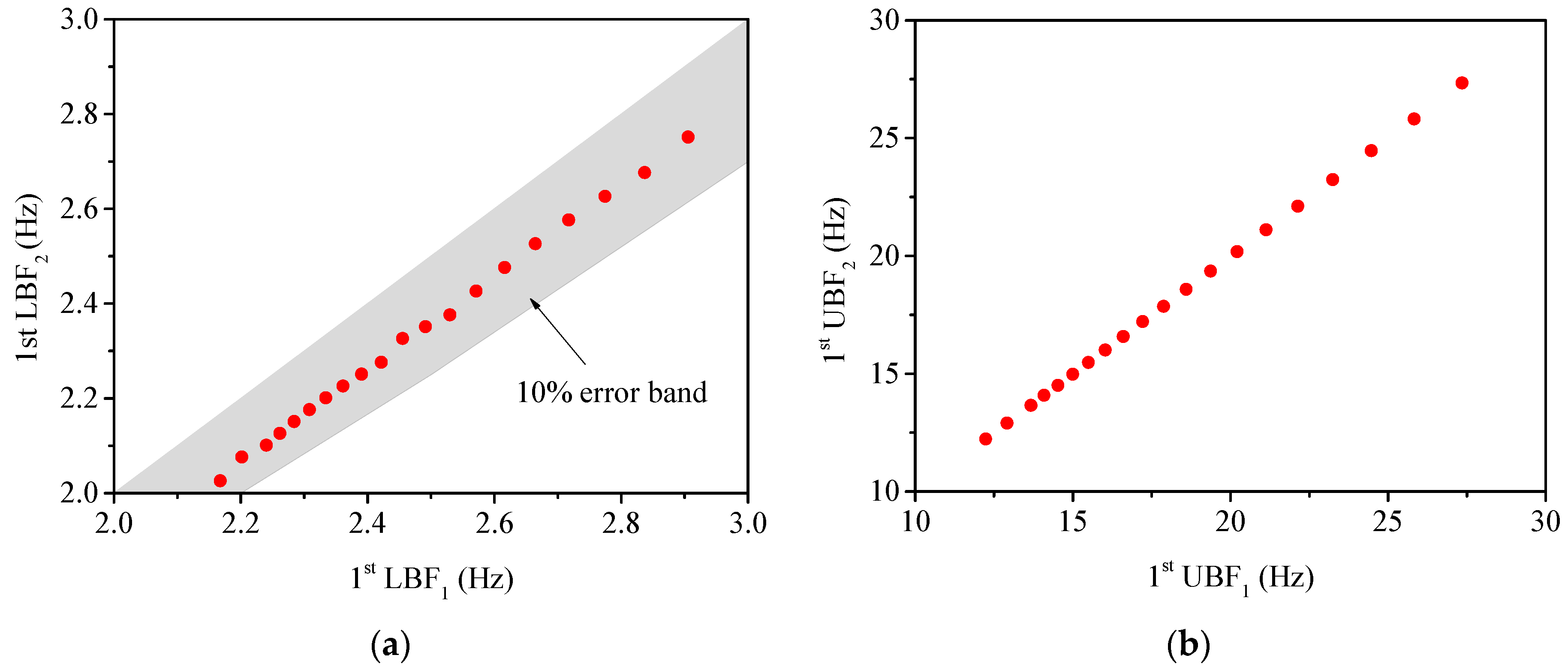
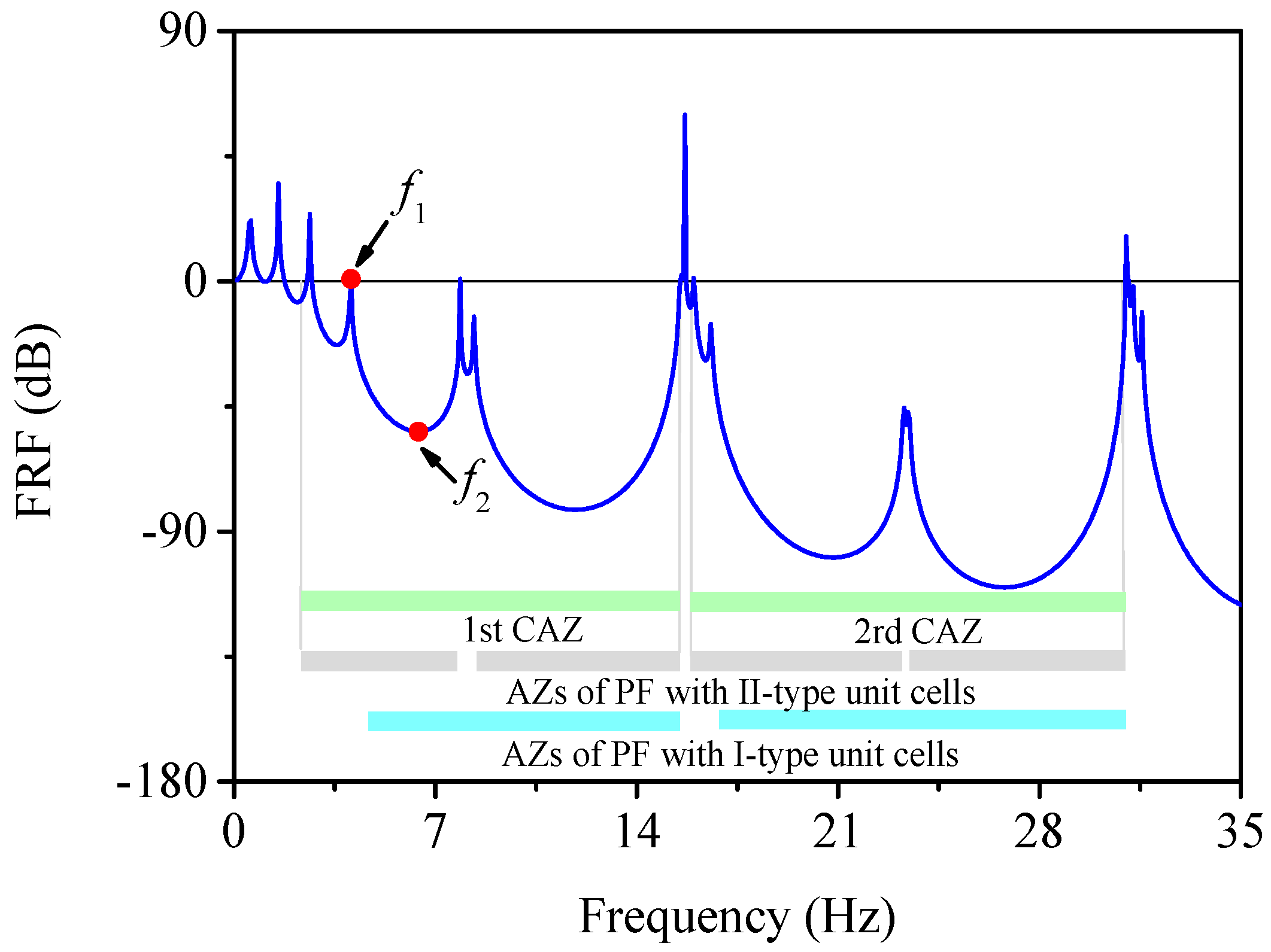
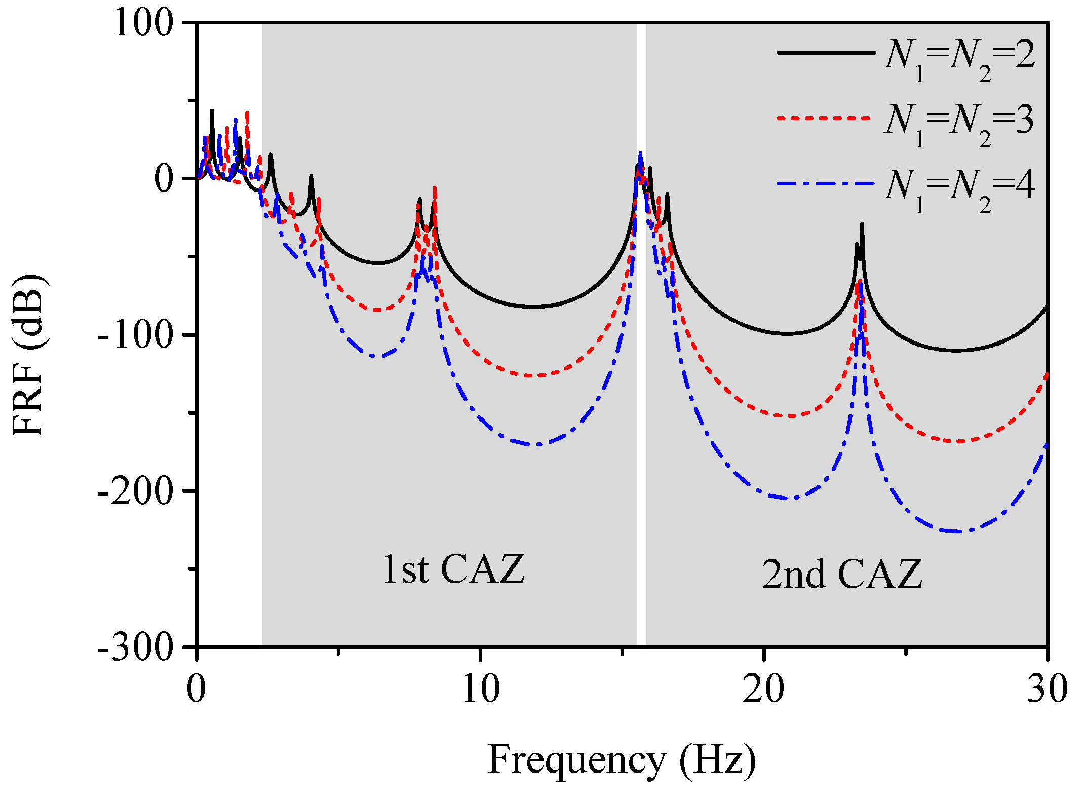
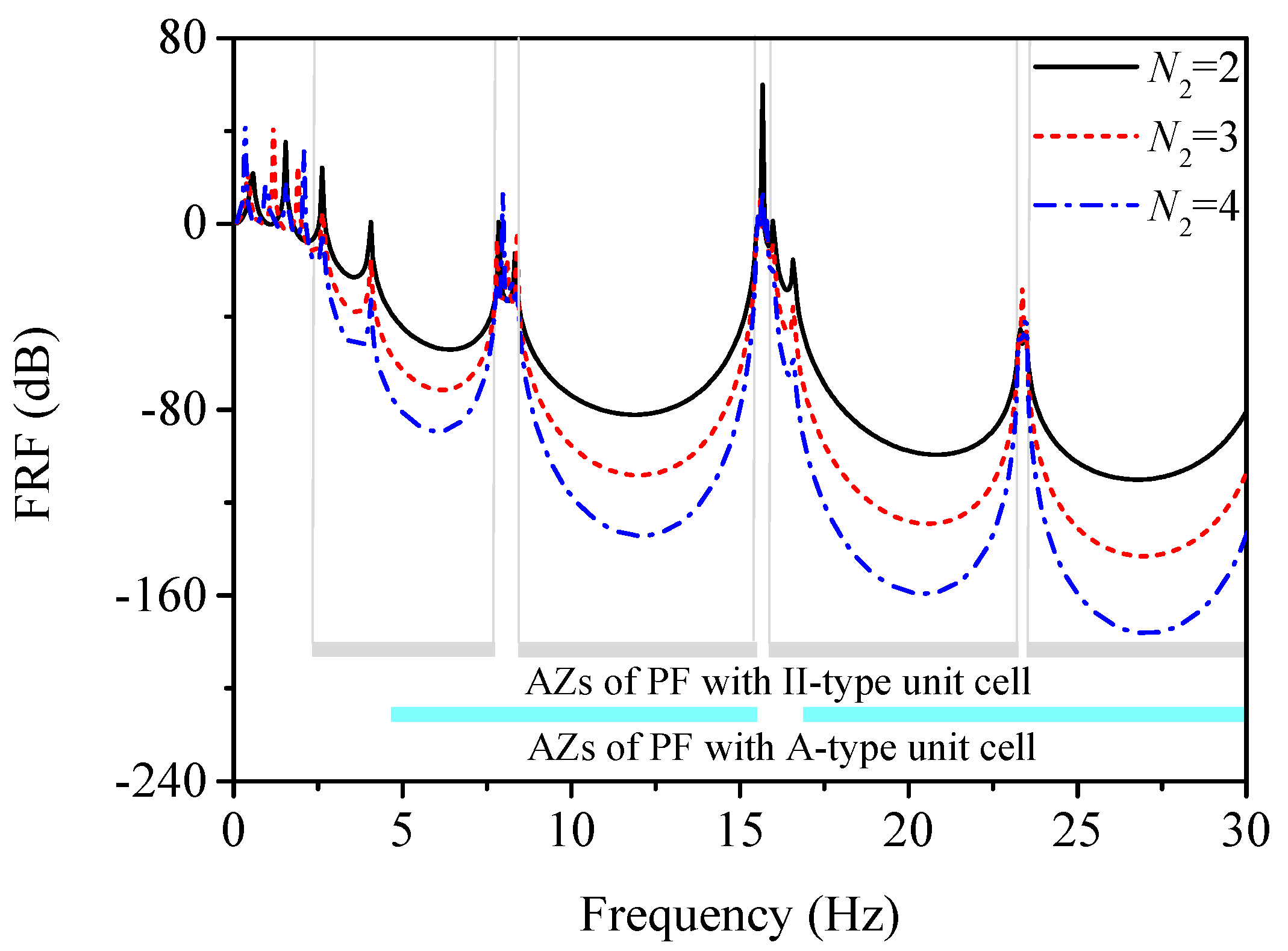
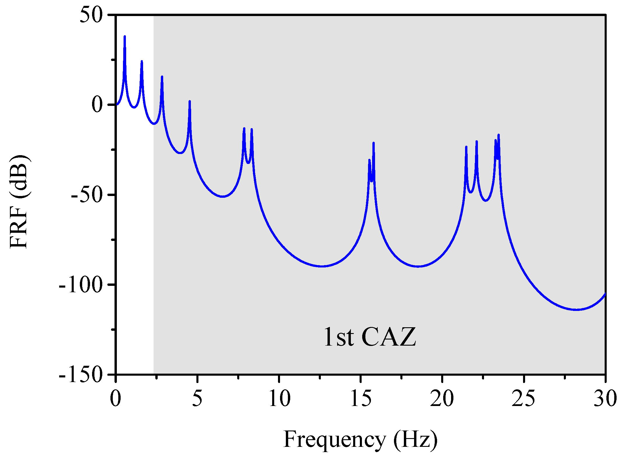
3.2. Combined Attenuation Zones of CLPFs

Figure 6 shows FRF of the CLPF with N1 = 2 and N2 = 2, where the geometric parameters of Ι–type unit cell are a = 0.5 m and fr = 30% while those of ΙΙ–type unit cell are b = 1 m and fr = 30%. For comparison purposes, the corresponding AZs of the traditional LPFs with Ι–type and ΙΙ–type unit cells obtained by Equation (6) are plotted as the blue shaded areas (the first two AZs are 4.67–15.50 Hz and 16.88–30.99 Hz) and grey shaded areas (the first two AZs are 2.33–7.75 Hz and 8.44–15.50 Hz) in Figure 6, respectively. The green shaded areas are the so-called CAZs, which are a union of AZs of the traditional LPFs with Ι–type and ΙΙ–type unit cells. It can be seen from Figure 6 that the frequency ranges of negative FRFs match well with the CAZs except for frequencies 2.63, 4.07 and 7.86 Hz, which are near the boundaries of AZs of the traditional LPFs with Ι–type and ΙΙ–type unit cells. Figure 7 shows the displacement amplitude of nodes along the z direction of the CLPF under excitation frequencies f1 = 4.07 Hz and f2 = 6.41 Hz. It should be noted that f1 = 4.07 Hz is in the first AZ of traditional LPF with ΙΙ–type unit cells but outside the AZs of traditional LPF with Ι–type unit cells. It can be seen from Figure 7 that for f1 = 4.07 Hz, deformation of the rubber layers of the CLPF increases propagating in Ι–type unit cells and then decreases in ΙI–type unit cells in the CLPF, which leads to a slight amplification of the displacement amplitude of the top layer compared with that of the bottom layer. On the other hand, f2 = 6.41 Hz is in both the first AZs of the traditional LPFs with Ι–type and ΙΙ–type unit cells. Thus, in Figure 7, it can be seen that the displacement amplitude is significantly attenuated along the z direction for f2 = 6.41 Hz.
Figure 8 shows the LBF and UBF of the first CAZ (i.e., union of the AZs of the traditional LPFs with Ι–type and ΙΙ–type unit cells) and those of the frequency range of negative FRFs for 20 CLPFs with various filling ratios, where LBF1, UBF1, LBF2 and UBF2 represent the lower bound frequency and upper bound frequency of the first CAZ and those of the frequency range of negative FRFs, respectively. It can be seen from Figure 8 that the relative errors between LBF1 and LBF2 are less than 10% and those between UBF1 and UBF2 can be neglected, which verifies that the computation for the first CAZ simply by the union of the first AZs of the traditional LPFs with Ι–type and ΙΙ–type unit cells is sufficiently accurate in the engineering field.
Figure 9 shows the FRFs of the CLPF with various numbers of Ι–type and ΙΙ–type unit cells. It can be seen from Figure 9 that the excitation attenuation in the CAZs is larger as the numbers of Ι–type and ΙΙ–type unit cells in the CLPF increases, which is in accordance with the results in the previous studies of traditional LPFs [18].
Figure 10 shows the FRFs of the CLPF with two Ι–type unit cells and various numbers of ΙΙ–type unit cells. It can be seen from Figure 10 that only excitations in the AZs of the traditional LPFs with ΙΙ–type unit cells are attenuated more drastically as the numbers of ΙΙ–type unit cells in the CLPF increases, while those outside AZs of the traditional LPFs with ΙΙ–type unit cells are almost not affected. Figure 11 shows the FRFs of the CLPF with various numbers of Ι–type unit cells and two ΙΙ–type unit cells. Similarly to the phenomenon in Figure 10, it can be seen from Figure 11 that only excitations in the AZs of the traditional LPFs with Ι–type unit cells are more drastically attenuated as the numbers of Ι–type unit cells in the CLPF increases, while those outside the AZs of the traditional LPFs with Ι–type unit cells are almost not affected, which implies that the generation of CAZs of CLPFs results from both the contribution of the AZs of both the traditional LPFs with Ι–type and ΙΙ–type unit cells.

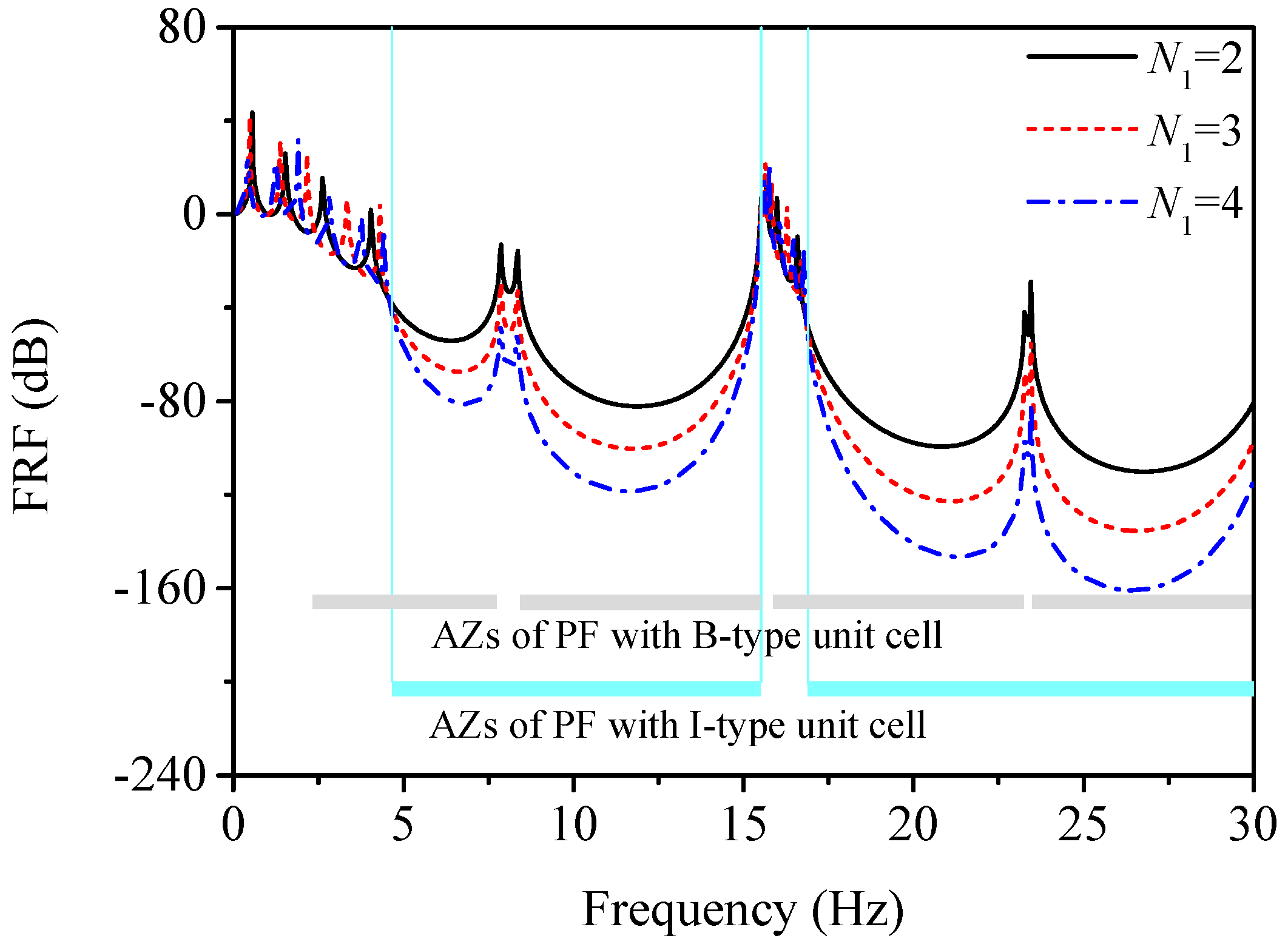
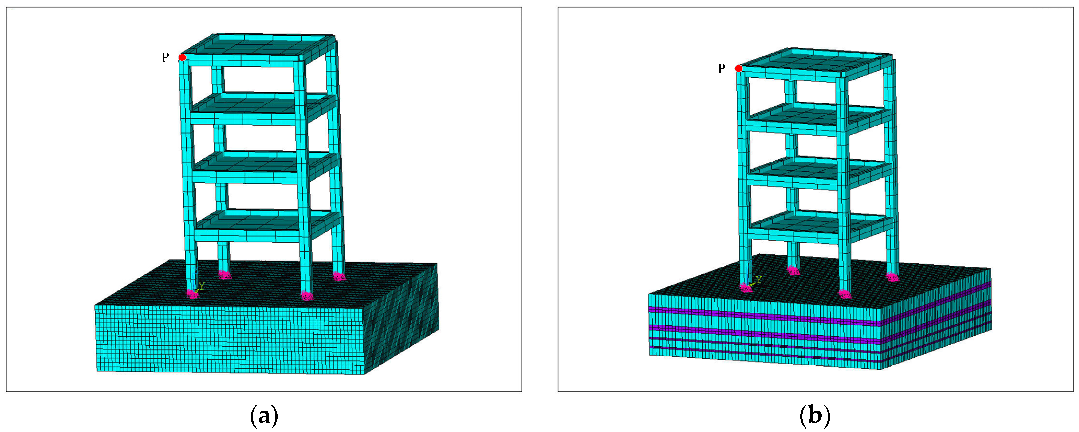
3.3. Seismic Performance of CLPFs

In this section, a CLPF with N1 = N2 = 2 and optimized geometric parameters is designed and its seismic performance is investigated. The geometric parameters of Ι–type unit cell are a = 0.5 m and fr = 22%, and those of the ΙΙ–type unit cell are b = 1 m and fr = 30%. Hence, the thickness of the designed CLPF is 3.39 m. Figure 12 shows the FRF of the CLPF with optimized geometric parameters, where the first CAZ can be identified from 2.33 to 30 Hz. Compared with previous studies on traditional LPFs [6,17], the CAZ of this CLPF is featured with both a lower starting frequency and larger bandwidth.
For comparison purposes, a pure concrete foundation with the same thickness as the designed CLPF is also considered, as shown in Figure 13a. The finite element model of the CLPF with a four-story concrete structure is shown Figure 13b. The plane dimensions of the concrete foundation and CLPF is 14 m × 14 m. The size of the upper structure is 6 m × 6 m × 12 m. The cross-section of the beams and columns are 0.4 m × 0.6 m and 0.5 m × 0.5 m, respectively. The thickness of the floors is 0.1 m.

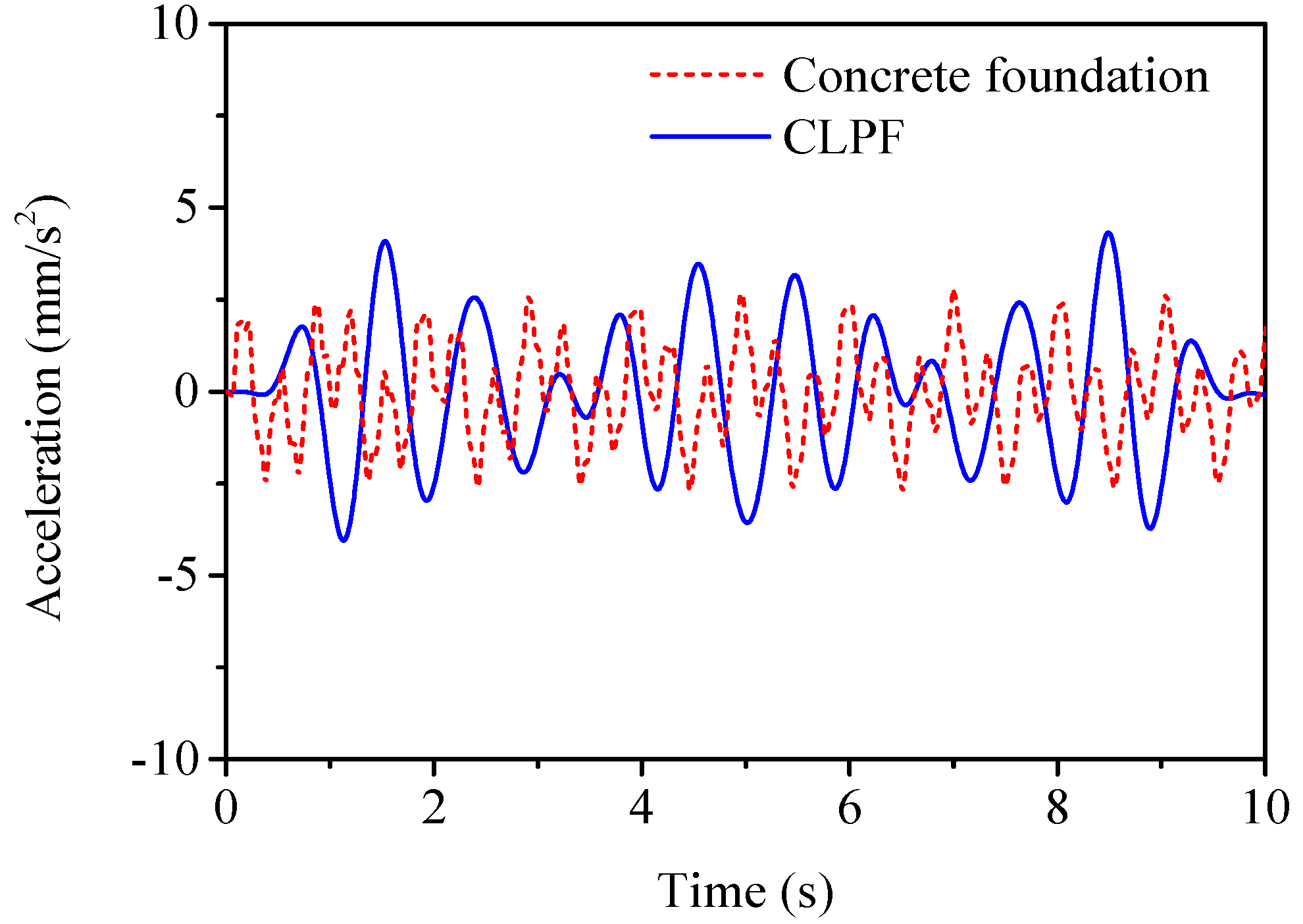
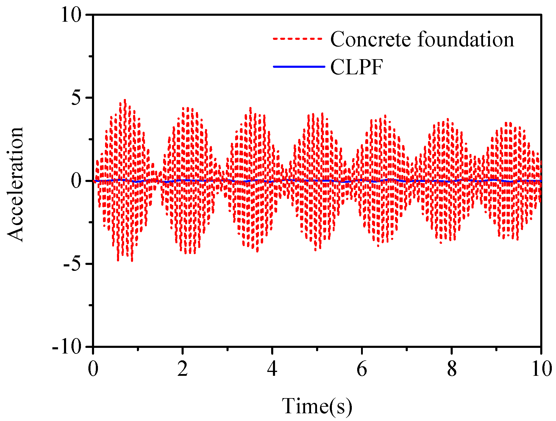
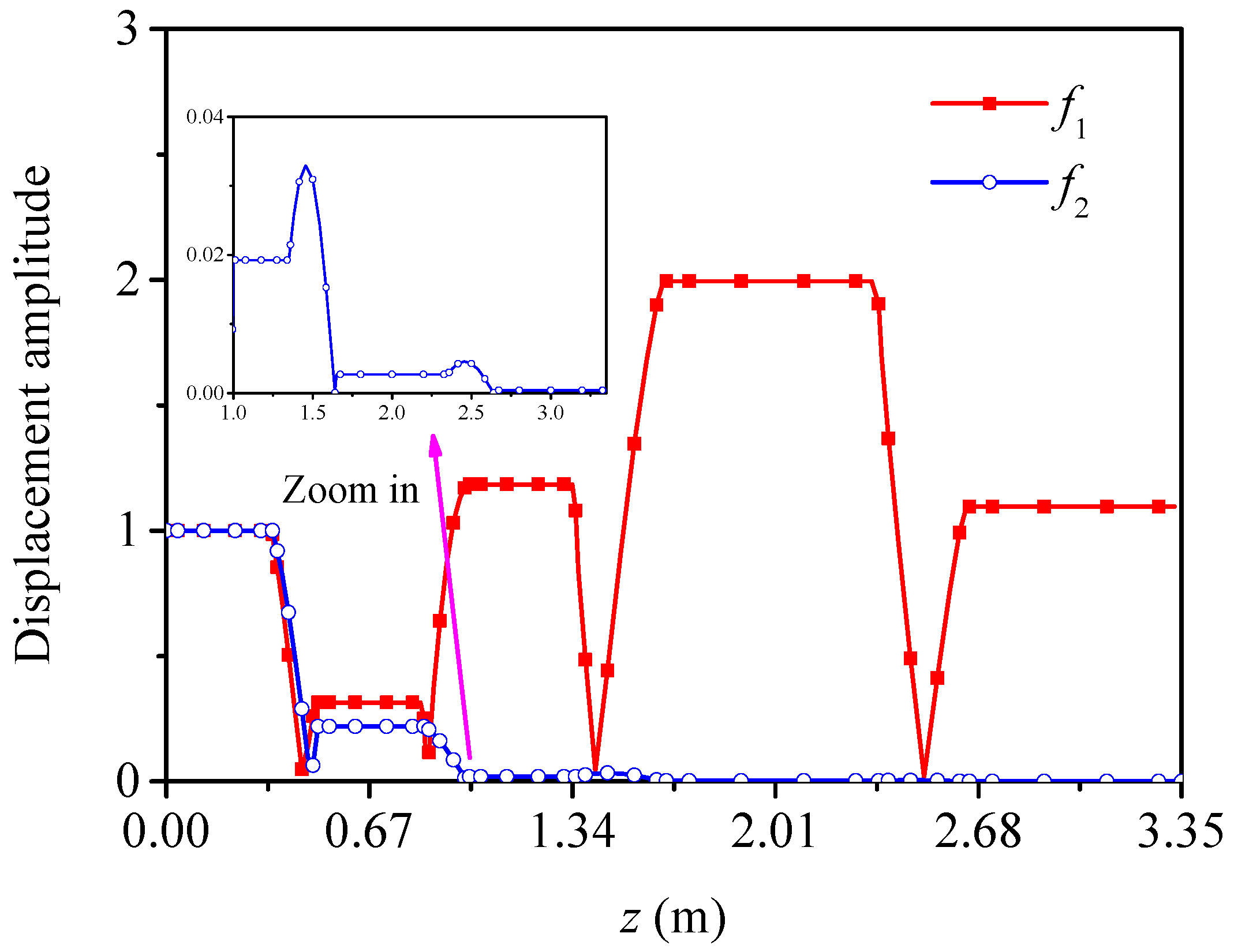
3.3.1. Time-Domain Response under Harmonic Excitations

Figure 14 shows the acceleration responses of the node P under harmonic excitation with frequency f = 2 Hz, which is outside the first CAZ of the CLPF. It can be found from Figure 14 that the acceleration response of node P with the CLPF is slightly larger than that with the concrete foundation. Figure 15 shows the acceleration responses of node P under harmonic excitation with frequency f = 10 Hz, which is in the first CAZ of the CLPF. It can clearly be seen from Figure 15 that the acceleration response of node P with the CLPF decreases compared with that with the concrete foundation, which verifies the theoretical results of CAZs in Section 3.2.

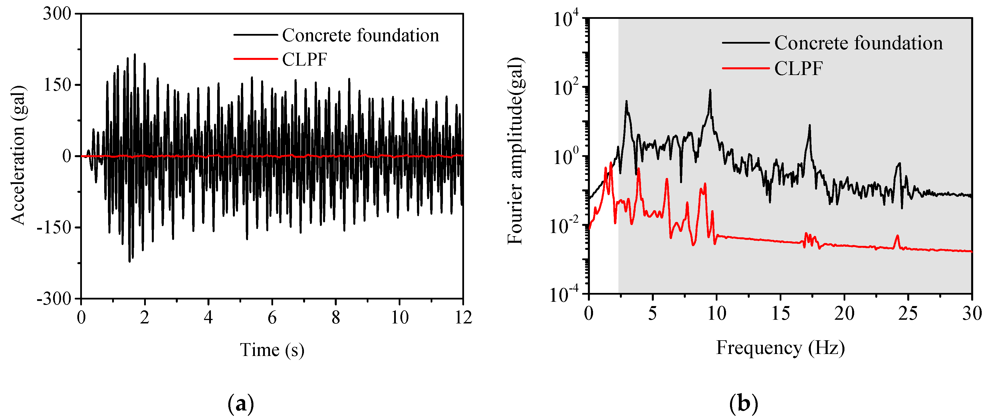
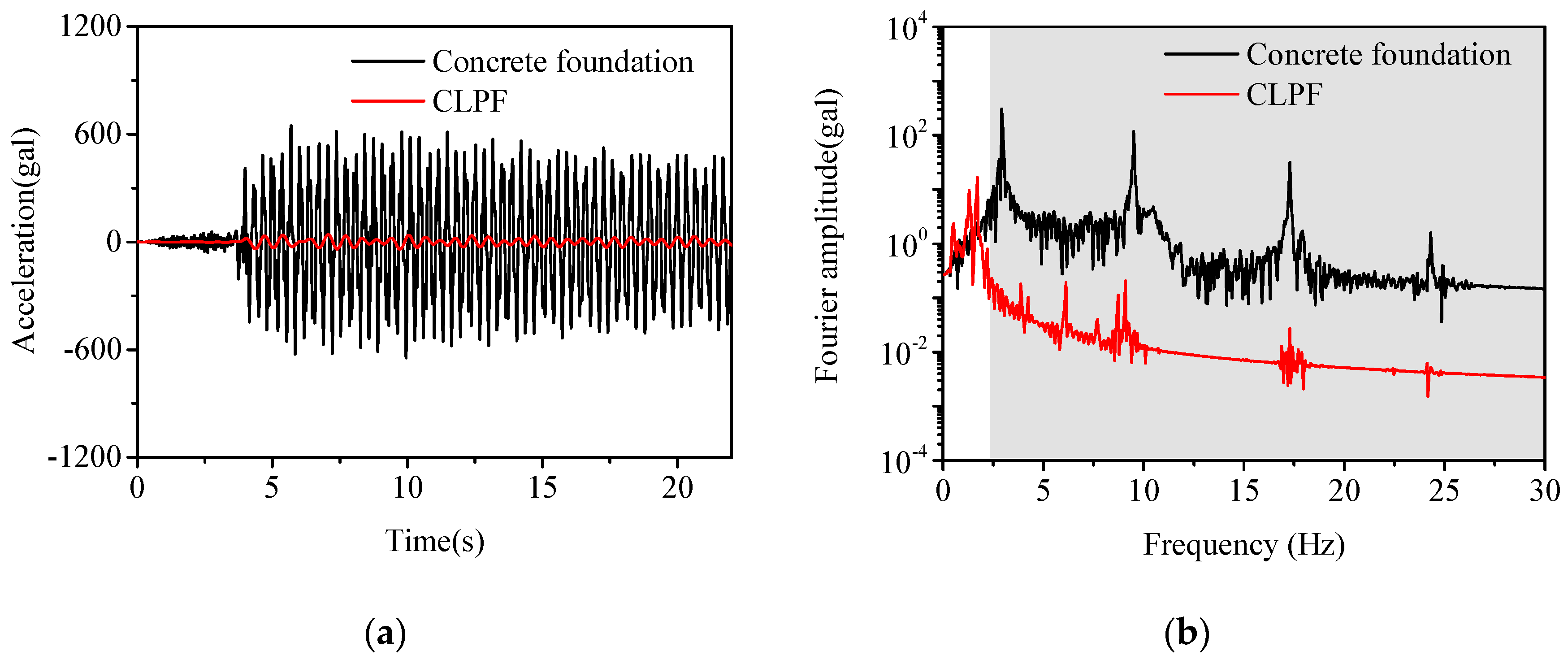
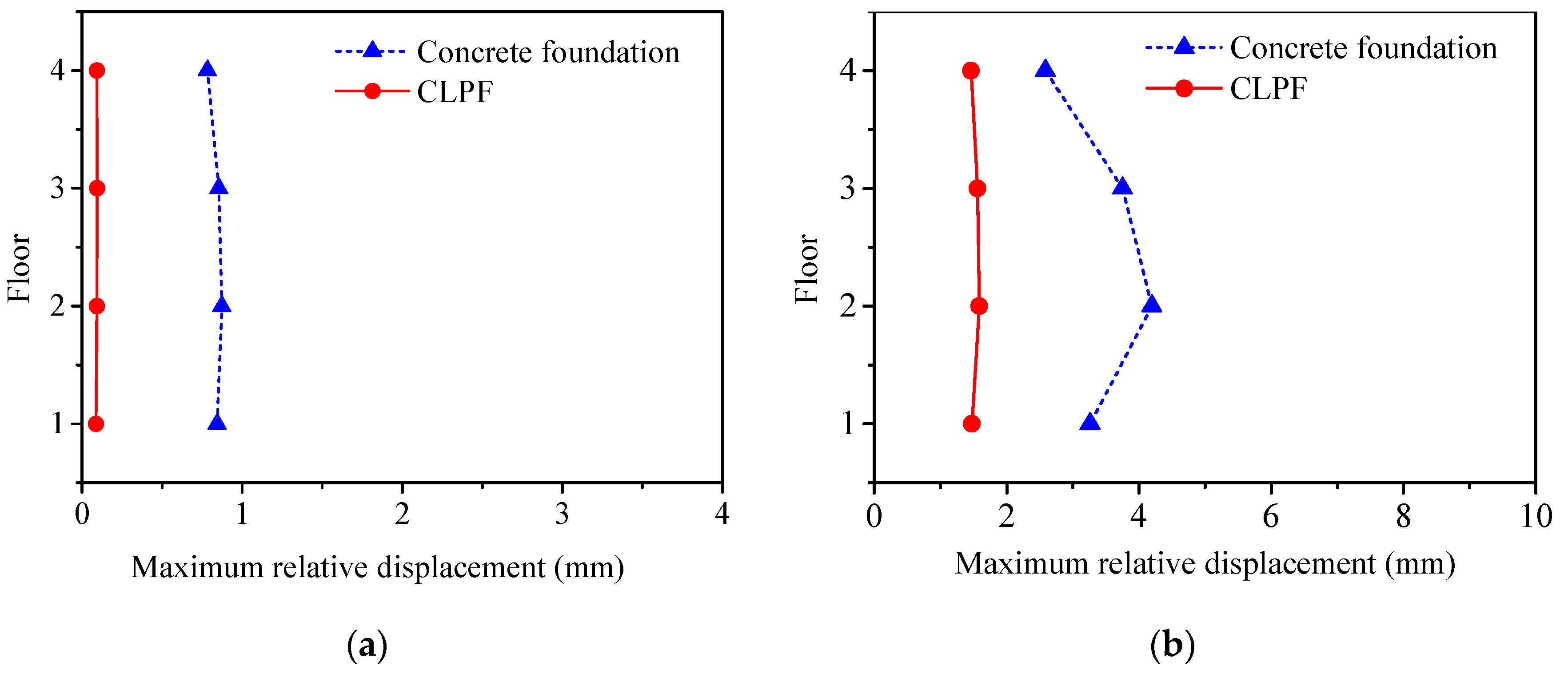
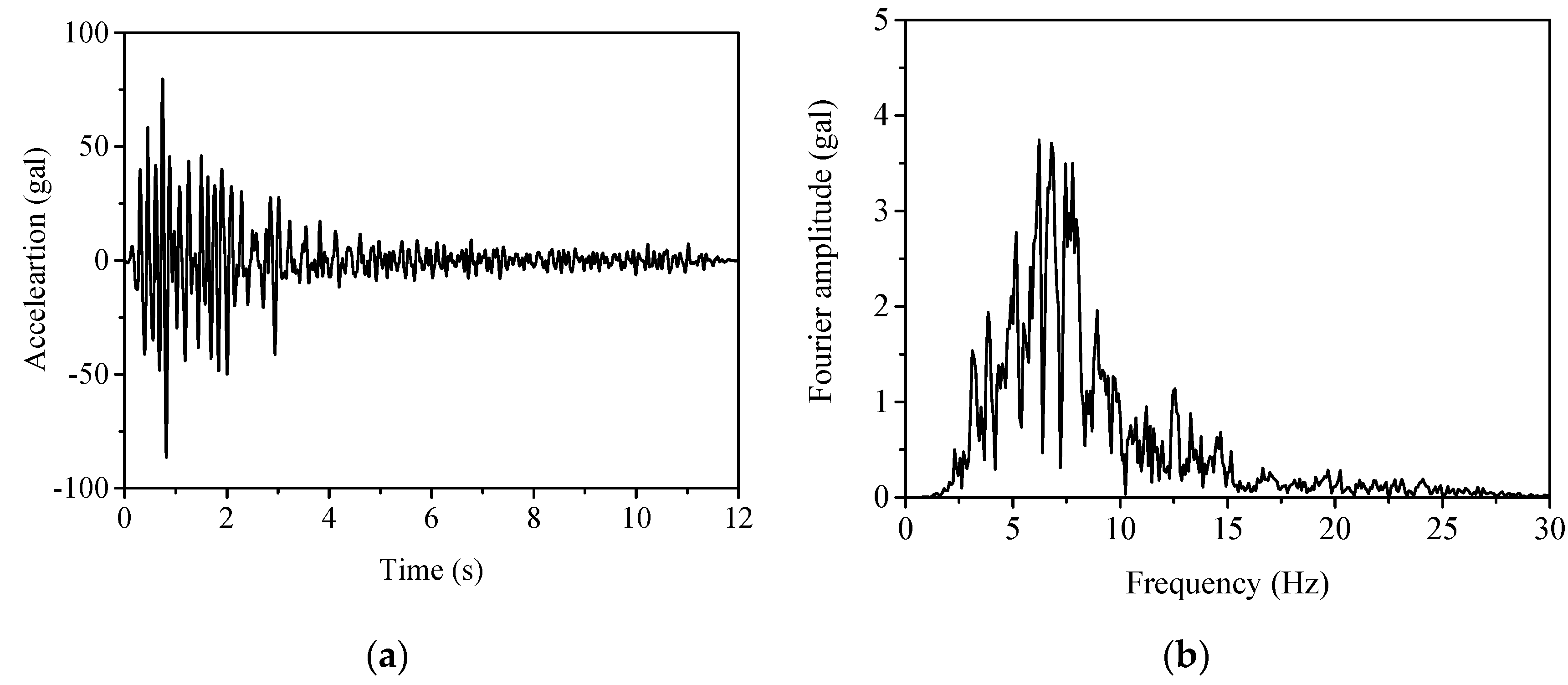
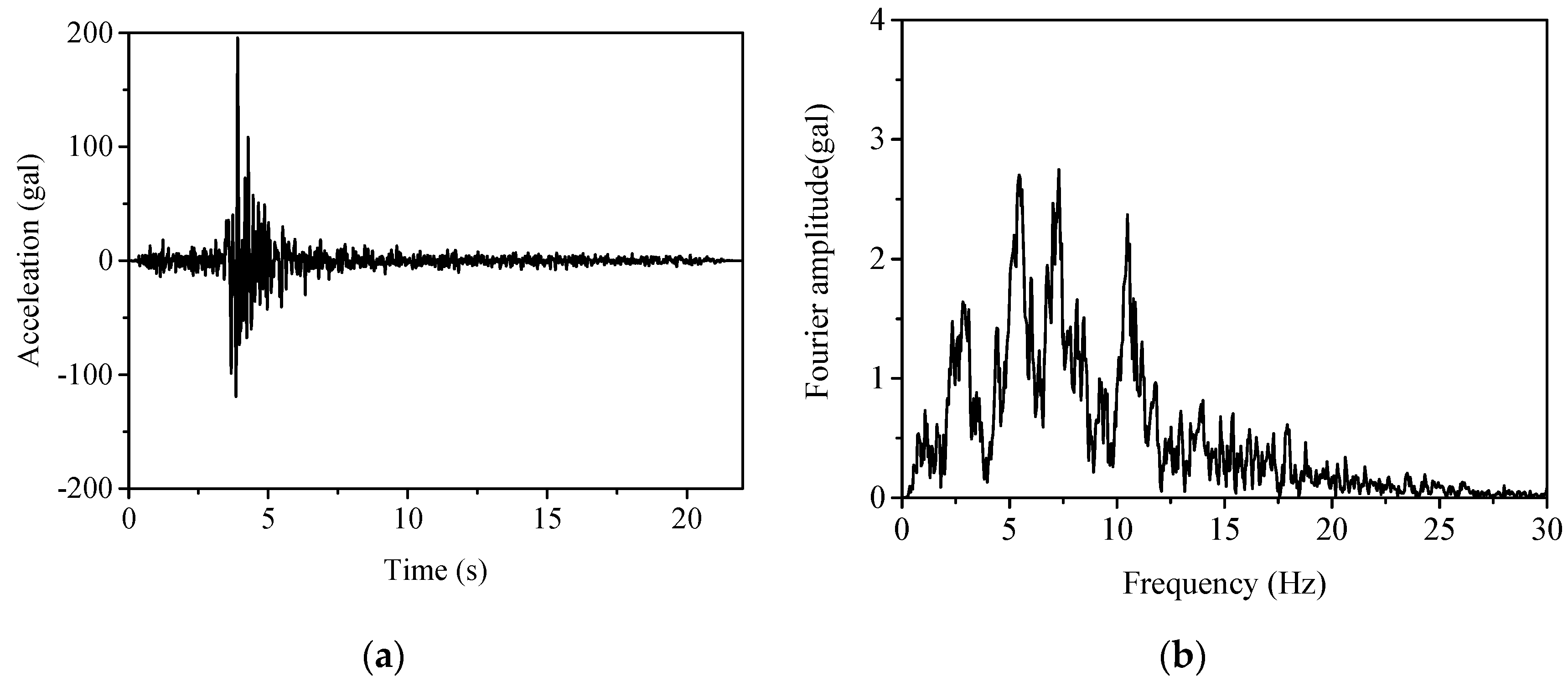
3.3.2. Time-Domain Response under Seismic Excitations

Horizontal components of the Whittier Narrows–02 and Oroville–01 earthquake ground motions are used as seismic excitations. These two seismic records are documented in the PEER Ground Database [29], whose relevant information is listed in Table 2.
Figure 16 shows the acceleration record of the Whittier Narrows–02 seismic wave and its Fourier spectra. It can be seen from Figure 16 that the dominant frequencies of the Whittier Narrows–02 seismic wave are from 3 to 8 Hz, which are covered by the first CAZ of the CLPF (2.33 to 30 Hz). Figure 17 shows the acceleration of node P under the Whittier Narrows–02 seismic wave and its Fourier spectra, where the shaded area is the first CAZ of the CLPF. It can be found from Figure 17 that the acceleration of node P with the CLPF is effectively reduced compared with that with the concrete foundation, which results in the reduction in the corresponding acceleration components in the first CAZ.
Figure 18 shows the acceleration record of the Oroville–01 seismic wave and its Fourier spectra. It can be seen from Figure 18 that the dominant frequencies of the Oroville–01 seismic wave are from 2.5 to 12 Hz, which are also covered by the first CAZ of the CLPF. Figure 19 shows the acceleration of node P under the Oroville–01 seismic wave and its Fourier spectra. Again, it can be seen from Figure 19a that the acceleration of node P with the CLPF is greatly reduced compared with that of the concrete foundation. Moreover, it can be seen from Figure 19b that the acceleration components outside the first CAZ will be enlarged by the CLPF, which is in accordance with the essence of AZs of traditional LPFs.
Figure 20 shows the maximum relative displacement of the superstructure under the Whittier Narrows–02 and Oroville–01 seismic waves. It can be seen from Figure 20 that seismic responses of the superstructure are effectively mitigated by the CLPF.

4. Conclusions

Combined layered periodic foundations are proposed by combing two traditional layered periodic foundations with different unit cells in tandem. Combined attenuation zones of the combined layered periodic foundations are identified by investigating the frequency response functions. The generation mechanism of the combined attenuation zones was studied by varying the configuration of combined layered periodic foundations. Seismic performance of a combined layered periodic foundation is studied to verify the theoretical findings of combined attenuation zones. The following conclusions can be drawn:
(1) The generation of the combined attenuation zones of combined layered periodic foundations results from the contribution of the attenuation zones of both the traditional layered periodic foundations.
(2) The first combined attenuation zone of a combined layered periodic foundation can be simply obtained by the union of the first attenuation zones of the traditional layered periodic foundations with acceptable accuracy in the engineering field.
(3) Combined attenuation zones of combined layered periodic foundations are of both comparatively low starting frequency and large bandwidth, which is an advantage in the field of seismic isolation that the traditional layered periodic foundations do not have.

Author Contributions

X.L. conceived this original work; Y.R. performed the numerical analysis and wrote the paper; X.S. edited and polished the paper. All authors have read and agreed to the published version of the manuscript.

Funding

This research is funded by the National Natural Science Foundation of China (51808007).

Institutional Review Board Statement

Not applicable.

Informed Consent Statement

Not applicable.

Data Availability Statement

Not applicable.

Conflicts of Interest

The authors declare no conflict of interest.

References

  1. Guo, Z.; Pan, J.; Sheng, M. Vibro-Acoustic performance of a sandwich plate with periodically inserted resonators. Appl. Sci. 2019, 9, 3651. [Google Scholar] [CrossRef] [Green Version]
  2. Qin, Q.; Sheng, M.; Guo, Z. Low-Frequency vibration and radiation performance of a locally resonant plate attached with periodic multiple resonators. Appl. Sci. 2020, 10, 2843. [Google Scholar] [CrossRef] [Green Version]
  3. Jia, G.F.; Shi, Z.F. A new seismic isolation system and its feasibility study. Earthq. Eng. Eng. Vib. 2010, 9, 75–82. [Google Scholar] [CrossRef]
  4. Basone, F.; Wenzel, M.; Bursi, O.S.; Fossetti, M. Finite locally resonant metafoundations for the seismic protection of fuel storage tanks. Earthq. Eng. Struct. Dyn. 2019, 48, 232–252. [Google Scholar] [CrossRef]
  5. Dertimanis, V.K.; Antoniadis, I.A.; Chatzi, E.N. Feasibility analysis on the attenuation of strong ground motions using finite periodic lattices of mass-in-mass barriers. J. Eng. Mech. 2016, 142, 04016060. [Google Scholar] [CrossRef]
  6. Bao, J.; Shi, Z.F.; Xiang, H.J. Dynamic responses of a structure with periodic foundations. J. Eng. Mech. 2012, 138, 761–769. [Google Scholar] [CrossRef]
  7. Witarto, W.; Wang, S.J.; Nie, X.; Mo, Y.L.; Shi, Z.F.; Tang, Y.; Kassawara, R.P. Analysis and design of one dimensional periodic foundations for seismic base isolation of structures. Int. J. Eng. Res. Appl. 2016, 6, 5–15. [Google Scholar]
  8. Yan, Y.Q.; Laskar, A.; Cheng, Z.B.; Menq, F.; Tang, Y.; Mo, Y.L.; Shi, Z.F. Seismic isolation of two dimensional periodic foundations. J. Appl. Phys. 2014, 116, 044908. [Google Scholar] [CrossRef]
  9. Huang, J.K.; Shi, Z.F.; Huang, W.X.; Chen, X.H. A periodic foundation with rotational oscillators for extremely low-frequency seismic isolation: Analysis and experimental verification. Smart Mater. Struct. 2017, 26, 035061. [Google Scholar] [CrossRef]
  10. Cheng, Z.B.; Shi, Z.F. Composite periodic foundation and its application for seismic isolation. Earthq. Eng. Struct. Dyn. 2018, 47, 925–944. [Google Scholar] [CrossRef]
  11. Liu, X.N.; Wang, Y.H.; Chen, Y.C. Attenuation zones of two dimensional periodic foundations including the effect of vertical loads. Appl. Sci. 2019, 9, 993. [Google Scholar] [CrossRef] [Green Version]
  12. Yan, Y.Q.; Cheng, Z.B.; Meng, F.; Mo, Y.L.; Tang, Y.; Shi, Z.F. Three dimensional periodic foundations for base seismic isolation. Smart Mater. Struct. 2015, 24, 075006. [Google Scholar] [CrossRef]
  13. Witarto, W.; Wang, S.J.; Yang, C.Y.; Wang, J.; Mo, Y.L.; Chang, K.C.; Tang, Y. Three-Dimensional periodic materials as seismic base isolator for nuclear infrastructure. AIP Adv. 2019, 9, 045014. [Google Scholar] [CrossRef] [Green Version]
  14. Sun, F.F.; Xiao, L.; Bursi, O.S. Quantification of seismic mitigation performance of periodic foundations with soil-structure interaction. Soil Dyn. Earthq. Eng. 2020, 132, 106089. [Google Scholar] [CrossRef]
  15. Xiong, C.; Shi, Z.F.; Xiang, H.J. Attenuation of Building Vibration using periodic foundations. Adv. Struct. Eng. 2012, 15, 1375–1388. [Google Scholar] [CrossRef]
  16. Xiang, H.J.; Shi, Z.F.; Wang, S.J.; Mo, Y.L. Periodic materials-based vibration attenuation in layered foundations: Experimental validation. Smart Mater. Struct. 2012, 21, 112003. [Google Scholar] [CrossRef]
  17. Shi, Z.F.; Cheng, Z.B.; Xiang, H.J. Seismic isolation foundations with effective attenuation zones. Soil Dyn. Earthq. Eng. 2014, 57, 143–151. [Google Scholar] [CrossRef]
  18. Liu, X.N.; Shi, Z.F.; Mo, Y.L.; Cheng, Z.B. Effect of initial stress on attenuation zones of layered periodic foundations. Eng. Struct. 2016, 121, 75–84. [Google Scholar] [CrossRef]
  19. Cheng, Z.B.; Shi, Z.F.; Palemo, A.; Xiang, H.J.; Guo, W. Seismic vibrations attenuation via damped layered periodic foundations. Eng. Struct. 2020, 211, 110427. [Google Scholar] [CrossRef]
  20. Witarto, W.; Nakshatrala, K.B.; Mo, Y.L. Global sensitivity analysis of frequency band gaps in one-dimensional phononic crystals. Mech. Mater. 2019, 134, 38–53. [Google Scholar] [CrossRef] [Green Version]
  21. Liu, X.N.; Ren, Y.Q.; Song, X.R.; Witarto, W. A global sensitivity analysis method based on the Gauss-Lobatto integration and its application in layered periodic foundations with initial stress. Compos. Struct. 2020, 244, 112297. [Google Scholar] [CrossRef]
  22. Miniaci, M.; Krushynska, A.; Bosia, F.; Pugno, N.M. Large scale mechanical metamaterials as seismic shields. New J. Phys. 2016, 18, 083041. [Google Scholar] [CrossRef]
  23. Liu, H.; Kuang, Z.B.; Cai, Z.M. Propagation of Bleustein–Gulyaev waves in a prestressed layered piezoelectric structure. Ultrasonics 2003, 41, 397–405. [Google Scholar] [CrossRef]
  24. Zhong, H.Z.; Yu, T. A weak form quadrature element method for plane elasticity problems. Appl. Math. Model. 2009, 33, 3801–3814. [Google Scholar] [CrossRef]
  25. Liu, X.N.; Shi, Z.F.; Mo, Y.L. Attenuation zones of initially stressed periodic mindlin plates on an elastic foundation. Int. J. Mech. Sci. 2016, 115–116, 12–23. [Google Scholar] [CrossRef] [Green Version]
  26. Yuan, S.; Du, J.N. Upper bound limit analysis using the weak form quadrature element method. Appl. Math. Model. 2018, 56, 551–563. [Google Scholar] [CrossRef]
  27. Yuan, S.; Du, J.N. Effective stress-based upper bound limit analysis of unsaturated soils using the weak form quadrature element method. Comput. Geotech. 2018, 98, 172–180. [Google Scholar] [CrossRef]
  28. Meng, L.K.; Cheng, Z.B.; Shi, Z.F. Vibration mitigation in saturated soil by periodic pile barriers. Comput. Geosci. 2020, 117, 103251. [Google Scholar] [CrossRef]
  29. Peer Ground Motion Database. 2012. Available online: http://peer.berkeley.edu/peer_ground_motion_database (accessed on 14 July 2020).
Figure 1. Traditional layered periodic foundation with identical unit cells.
Applsci 11 07114 g001
Figure 2. (a) Ι–type unit cell with thickness a and (b) ΙΙ–type unit cell with thickness b.
Applsci 11 07114 g002
Figure 3. Combined layered periodic foundation with N1 Ι–type and N2 ΙΙ–type unit cells.
Applsci 11 07114 g003
Figure 4. AZs and FRFs of traditional layered periodic foundations with (a) Ι–type and (b) ΙΙ–type unit cells.
Applsci 11 07114 g004
Figure 5. AZs of traditional layered periodic foundations with (a) Ι–type and (b) ΙΙ–type unit cells changing with the filling ratio of rubber material.
Applsci 11 07114 g005
Figure 6. FRF of the combined layered periodic foundation with N1 = 2 and N2 = 2. (The geometric parameters of Ι–type unit cell are a = 0.5 m and fr = 30%, and those of ΙΙ–type unit cell are b = 1 m and fr = 30%).
Applsci 11 07114 g006
Figure 7. Displacement amplitude of nodes along the z direction of the combined layered periodic foundation under excitation frequencies f1 and f2.
Applsci 11 07114 g007
Figure 8. (a) LBF and (b) UBF of the first CAZ and those of the frequency range of negative FRFs.
Applsci 11 07114 g008
Figure 9. FRFs of the combined layered periodic foundation with various numbers of Ι–type and ΙΙ–type unit cells.
Applsci 11 07114 g009
Figure 10. FRFs of the combined layered periodic foundation with two Ι–type unit cells and various numbers of ΙΙ–type unit cells.
Applsci 11 07114 g010
Figure 11. FRFs of the combined layered periodic foundation with various numbers of Ι–type unit cells and two ΙΙ–type unit cells.
Applsci 11 07114 g011
Figure 12. FRF of the designed combined layered periodic foundation (the geometric parameters of Ι–type unit cell are a = 0.5 m and fr = 22%, and those of ΙΙ–type unit cell are b = 1 m and fr = 30%).
Applsci 11 07114 g012
Figure 13. (a) Concrete foundation and (b) combined layered periodic foundation with superstructure.
Applsci 11 07114 g013
Figure 14. Acceleration responses of node P under harmonic excitation with frequency f = 2 Hz.
Applsci 11 07114 g014
Figure 15. Acceleration responses of node P under harmonic excitation with frequency f = 10 Hz.
Applsci 11 07114 g015
Figure 16. (a) Acceleration record of the Whittier Narrows–02 seismic wave and (b) its Fourier spectra.
Applsci 11 07114 g016
Figure 17. (a) Acceleration of node P under Whittier Narrows–02 seismic wave and (b) its Fourier spectra.
Applsci 11 07114 g017
Figure 18. (a) Acceleration record of the Oroville–01 seismic wave and (b) its Fourier spectra.
Applsci 11 07114 g018
Figure 19. (a) Acceleration of node P under the Oroville–01 seismic wave and (b) its Fourier spectra.
Applsci 11 07114 g019
Figure 20. Maximum relative displacement of superstructure under: (a) the Whittier Narrows–02; and (b) the Oroville–01 seismic waves.
Applsci 11 07114 g020
Table 1. Material parameters.
MaterialsMass Density ρ (kg/m3)Young Modulus E (GPa)Poisson Ratio v
Concrete2300250.330
Rubber13001.37 × 10−40.463
Table 2. Earthquake acceleration records.
Earthquake (Record Place)Magnitude (Date)Acceleration Peak (Gal)
Whittier Narrows–02 (Big Tujunga Angeles Nat F)5.27 (4 October 1987)195.671
Oroville–01 (Oroville Seismograph Station)5.89 (1 August 1975)86.434
Publisher’s Note: MDPI stays neutral with regard to jurisdictional claims in published maps and institutional affiliations.

