Article

Optical Frequency Comb Expansion Using Mutually Injection-Locked Gain-Switched Lasers

by
Prajwal D. Lakshmijayasimha
1,*,
Prince M. Anandarajah
1,2,3,
Pascal Landais
1,3 and
Aleksandra Kaszubowska-Anandarajah
1,2
1
Photonics Systems and Sensing Lab., School of Electronic Engineering, Dublin City University, Glasnevin, D09 NA55 Dublin, Ireland
2
CONNECT Research Centre, Dunlop Oriel House, Trinity College Dublin, D02 PN40 Dublin, Ireland
3
ENTWINE, Dublin City University, Glasnevin, D09 NA55 Dublin, Ireland
*
Author to whom correspondence should be addressed.
Appl. Sci. 2021, 11(15), 7108; https://doi.org/10.3390/app11157108
Submission received: 26 June 2021 / Revised: 28 July 2021 / Accepted: 29 July 2021 / Published: 31 July 2021
(This article belongs to the Special Issue Research and Application of Semiconductor Lasers)

Abstract

:
We propose a novel scheme for the expansion and comb densification of gain-switched optical frequency combs (GS-OFC). The technique entails mutual injection locking of two gain-switched lasers with a common master to generate a wider bandwidth OFC. Subsequently, the OFC is further expanded and/or densified using a phase modulator with optimum drive conditions. We experimentally demonstrate the generation of an OFC with 45 highly correlated lines separated by 6.25 GHz with an expansion factor ~3. In addition, operating in comb densification mode, the channel spacing of the OFC is tuned from 6.25 GHz to 390.625 MHz. Finally, a detailed characterization of the lines, across the entire expanded comb, is reported highlighting the excellent spectral purity with linewidths of ~40 kHz, a relative intensity noise better than −152 dB/Hz, and a high degree of phase correlation between the comb lines. The proposed method is simple, highly flexible and the architecture is suitable for photonic integration, all of which make such an OFC extremely attractive for the employment in a multitude of applications.

1. Introduction

The development of optical frequency combs (OFCs) is considered one of the most important breakthroughs in the photonics field [1,2]. An OFC generates a series of evenly spaced, phase correlated spectral lines with a very stable free spectral range (FSR). These properties make them attractive to be employed in diverse applications such as spectroscopy [3], ranging [4], atomic clock [5], spectrally efficient optical communication networks [6,7,8,9,10], millimeter and terahertz generation [11] and many more [12]. In fiber optic communications systems, the outstanding stability of the FSR enables a reduction in the size of the guard bands thereby allowing ultra-dense channel spacing, significantly improving the spectral efficiency. Hence, the OFC can serve as an alternative solution to the existing laser array, for deployment in next-generation optical networks employing spectrally efficient schemes [13]. The high degree of phase correlation between the comb lines also makes them attractive in ultra-low noise microwave and terahertz generation systems [14]. Finally, the closely spaced combs enable high precision measurements in applications such as gas sensing and LIDAR [15,16].
The most prominent amongst the several semiconductor-based OFC generation techniques are based on mode-locked lasers (MLL) [17], Kerr effect-based micro-ring resonators [18], electro-optic modulators (EOM) [19], and gain-switched lasers (GSL) [20]. Each of these techniques has its pros and cons. In this article, we consider some of the most important criteria that need to be satisfied, for the employment of OFCs in a wide range of applications, such as (i) number of comb lines generated, (ii) free spectral range (FSR) tunability (from MHz to GHz range), (iii) low complexity and (iv) potential photonic integration. One of the promising approaches that satisfy the above-mentioned criteria entails the use of externally injected gain-switched laser (EI-GSL) [20]. The attractiveness of this technique stems from its simplicity (uses direct modulation), flexibility and cost-effectiveness. An EI-GSL-based comb features a tunable FSR, narrow linewidth (transferred from a master laser), and excellent phase correlation [21]. In addition, the EI-GSL scheme is suitable for photonic integration, further reducing the cost and footprint.
In recent years, the EI-GSL OFC has been extensively studied for various applications and some of the notable demonstrations include: (i) the realization of a superchannel transmitter employing spectrally efficient schemes such as Co-OFDM [22,23], coherent Nyquist WDM [6]; (ii) directly modulated DMT/PAM 4 for data center interconnects [24,25]; (iii) dual comb gas sensing spectroscopy [15,16,26]; (iv) soliton generation [27]; (v) absolute distance measurement [28] and (vi) analog radio-over-fiber distribution [14]. Furthermore, some of the photonic integrated circuit (PIC) versions of GSL sources are also realized in the form of a two-section device [29] and a four-section device [30,31]. This PIC realization highlights the huge potential of EI-GSL OFC and its suitability for commercial deployment. Nevertheless, some of the shortcomings of the EI-GSL OFC still need to be addressed such as (a) a limited number of comb lines, arising from the restricted intrinsic modulation bandwidth of the laser and (b) difficulty in generating low FSR OFC (<1 GHz). The latter requires DC biasing of the laser at or below the threshold and modulating the laser with short electrical pulses [32], thus increasing the complexing and reducing the power of the comb.
To increase the number of generated comb lines, numerous approaches have been demonstrated. Zhou et al. [21] employed an electro-optic phase modulator (PM) driven by an amplified sinewave (~4 × V π ) at the gain-switching frequency to expand the EI-GSL OFC by a factor of two. Another expansion technique [20,33] includes the use of dispersion compensation fiber (DCF) followed by highly non-linear fiber (HNLF) that led to an expansion by a factor of >3. More recently, a comb expansion technique involving several EI-GS Fabry Perot (FP) lasers in a parallel, with a semiconductor optical amplifier (SOA) introducing phase correlation was reported [34]. It resulted in an expansion factor >3 whilst also providing amplification of the comb lines. However, the architecture and components used increased the cost and complexity of the expanded OFC source. Other expansion schemes reported include the use of the dual-mode injection locking of an FP laser [35], cascaded EI-GS FP lasers [36], dual-drive MZM modulators [37], and of the dual-polarization effect in VCSELs [38]. However, these approaches resulted in a limited expansion and in an OFC with a poor optical carrier to noise ratio (OCNR). A summary of various GSL expansion approaches that have been reported is presented in Table 1.
In this article, we propose a novel architecture to expand the gain-switched laser-based OFC. In addition, we demonstrate that the same scheme facilitates a wide FSR tunability via comb densification. The expansion technique is based on the injection locking of two gain-switched lasers modulated at 6.25 GHz, with a common master laser. Their combined spectra generate a wide bandwidth OFC. Additional expansion is induced by a phase modulator driven at multiples of the gain-switching frequency, to achieve an expansion factor ~3, i.e., producing up to 45 lines and with an OCNR >45 dB (note: unless stated otherwise, the number of comb lines quoted in the article relates to lines within a 5 dB window from the spectral peak). Then, we demonstrate a wide FSR tunability from 390.625 MHz to 6.25 GHz by employing comb densification. Finally, we carry out a comprehensive characterization of the OFC to exemplify its excellent features. The optical linewidth of the comb lines was measured to be ~40 kHz, while their relative intensity noise (RIN) was better than −152 dB/Hz. The comb lines across the expanded OFC also show an excellent phase correlation. It is also important to note that the proposed architecture lends itself to photonic integration, further reducing the cost, size and energy consumption. Such simplicity, flexibility, FSR tuning (GHz to MHz), and potential photonic integration (PI) make the proposed OFC generation/expansion architecture extremely attractive for a wide range of applications.
This article is organized as follows: In Section 2, the operational principle and experimental setup of the proposed architecture are presented. Section 3 describes the experimental results: expansion, comb densification, following by detailed comb line characterization. Finally, Section 4 outlines the conclusions.

2. Mutually Injection-Locked Gain-Switched Laser

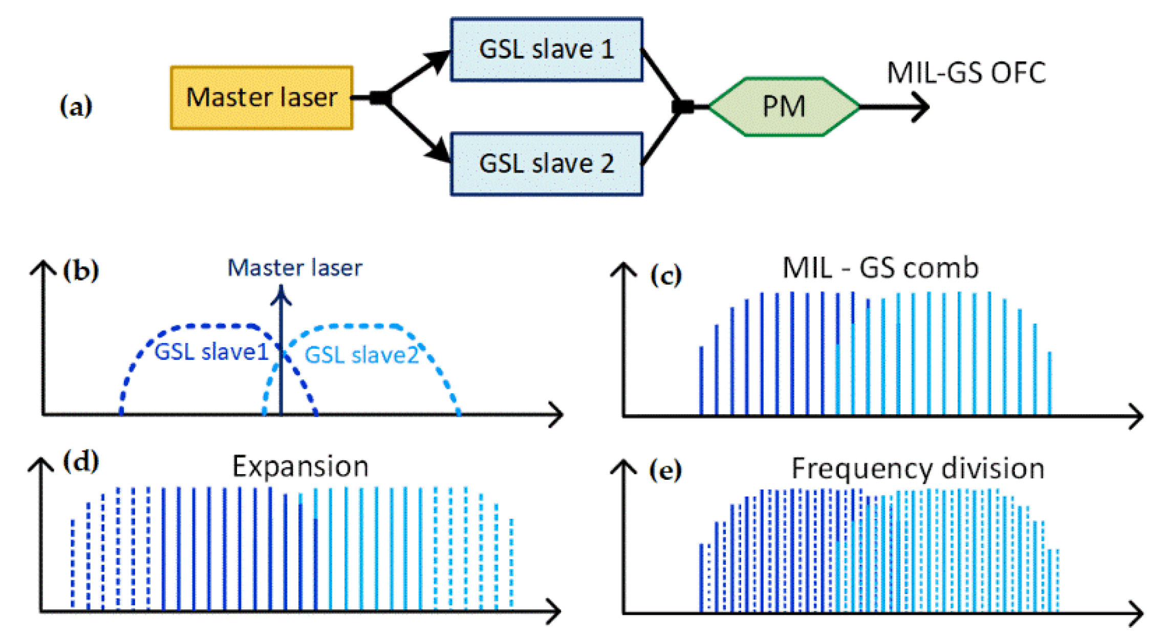
2.1. Operational Principle

The operational principle of the proposed scheme is as shown in Figure 1a, and the line graph is illustrated in Figure 1b–e. It comprises two expansion stages: (i) expanded OFC generation via mutually injection-locked gain-switched (MIL-GS) lasers, (ii) further expansion and comb densification. Two semiconductor-based single-mode lasers are chosen as slave lasers and are gain-switched (GS) using a sinusoidal signal. The two GS slave lasers are then injection-locked by a semiconductor-based tunable laser, acting as a common master, as illustrated in Figure 1b. The master laser provides the frequency and phase locking to both GS slave lasers, resulting in two OFCs emitting comb lines with a high degree of phase correlation between them. The two MIL-GS OFCs are then combined to generate a single broad OFC (Figure 1c). Subsequently, the combined MIL-GS OFCs are passed through a phase modulator (PM) for further expansion. Here, the PM can be operated in two modes: (a) expansion and (b) expansion and comb densification. Firstly, the MIL-GS OFC is expanded by driving the PM with a large voltage (multiples of V π ) RF signal at the gain-switching (fundamental) frequency ( f s ) , as depicted in Figure 1d. Later, the PM is driven with multiples of fundamental FSR ( n   ×   f s ), but at the same drive voltage as above. Secondly, in the comb densification mode (Figure 1e), the PM is driven with a sinusoidal signal that is at a sub-harmonic of the fundamental frequency ( f s m ) . This results in the generation of a comb with an FSR that is m-times smaller than the fundamental one, thus realizing a simple comb densification. In other words, the FSR of the MIL-GS OFC can be tuned from GHz to MHz, without the need to re-optimize the GSL. Additionally, the average OFC power remains unchanged across the tuning range, thus overcoming the reduction of comb output power for low FSRs [31].

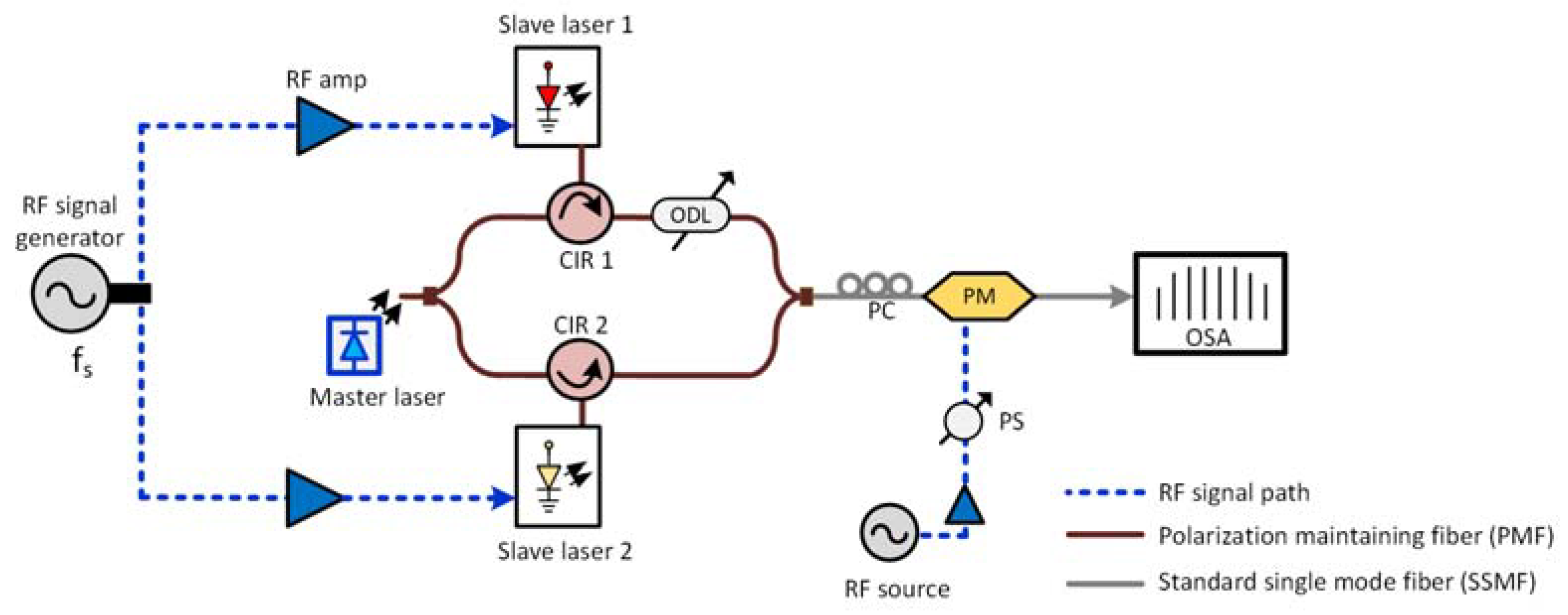
2.2. Experimental Setup

The experimental setup of the proposed MIL-GS OFC generation, expansion and comb densification scheme is shown in Figure 2. Here, the components with polarization maintaining fiber (PMF) and standard single mode fiber (SSMF) are indicated in brown and gray lines, respectively. Two commercially available discrete mode (DM) lasers, from Eblana Photonics [39] are chosen as the slave lasers. These are 250 µm long FP laser diodes with a slotted ridge waveguide structure that constrains the lasing in a longitudinal mode, with a side mode suppression ratio (SMSR) larger than 60 dB, as shown in Figure 3a. The DM lasers are encased in TEC controlled 7 pin butterfly packages with a k-type RF connector, to enable high-speed modulation, and without an optical isolator to allow external light injection. They exhibit threshold currents ( I t h ) of 10 mA and a modulation bandwidth of ~12 GHz, when biased at ~53 mA. At the same bias, slave laser 1 and 2 emits an average power of 6 dBm and 7 dBm, respectively. Gain switching is achieved by applying an amplified sinusoidal signal (~24 dBm) in conjunction with the 53 mA DC bias to both lasers. Subsequently, the temperature of the lasers is tuned to achieve a partial overlap of their spectra (as shown in Figure 3b). Then, a narrow linewidth tunable laser (Purephotonics PCL550, λ i n j e c t i o n = 1549.8 nm, P = −3 dBm), acting as a common master laser, is tuned to the overlapping wavelength region, split using a 50:50 splitter and injected, via 3 port circulators (CIR 1 and 2) into the two GS lasers. It is worth noting that the components used in the MIL-GS OFC generation scheme are pigtailed with polarization maintaining fiber, which is aligned to the slow axis.
The two-phase correlated OFCs generated this way are then combined using a 50:50 coupler and passed through a 20 GHz PM (EOspace). A polarization controller is used at the input of the PM to align the state of polarization of the input signal to that of PM. The modulator exhibits a V π of ~4 V (at 6.25 GHz) and is driven at ~13.5 Vpp (corresponds to 3.3 × V π ) by a second RF source (both RF sources are synchronized with 100 MHz reference signal). It is important to mention that the same RF source could be used for the OFC generation and the phase modulation. The expansion and spectral flattening (shaping) of the output comb are achieved by optimizing the synchronization between two arms using an optical delay line (ODL) for one arm, while RF phase shifter for another arm. In the expansion mode, the PM is driven at a frequency f = n · f s , with n = 1 , 2   or   3 , i.e., f = 6.25 ,   12.5 ,   18.75   GHz . Likewise, in the comb densification mode, the PM is driven at subharmonics of the fundamental frequency resulting in OFC FSRs of 3.125 ( f s 2 ) , 1.5625 GHz ( f s 4 ) , 781.25 MHz ( f s 8 ) , and 390.625 MHz ( f s 16 ) . The optical spectrum is recorded using a high resolution (20 MHz) optical spectrum and analyzer (OSA).

3. Results and Discussion

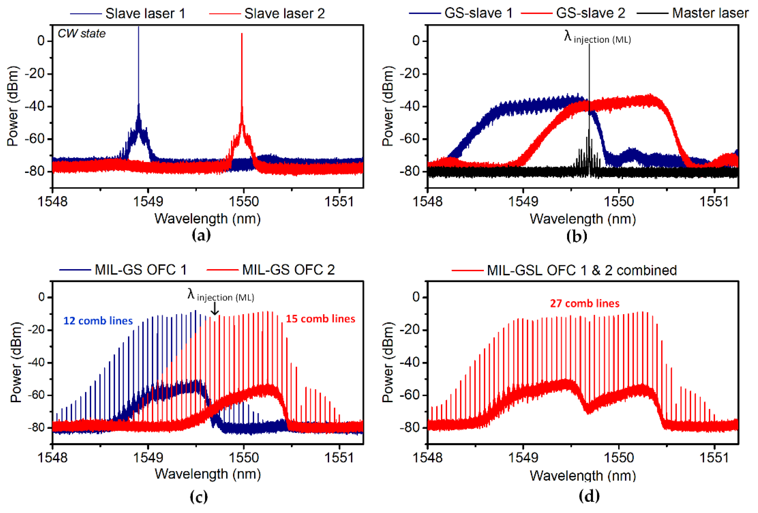
3.1. Expanded OFC Generation Using MIL-GS Lasers

The continuous wave (CW) optical spectra of the two slave lasers, with an SMSR >60 dB, is shown in Figure 3a. Figure 3b shows the overlapped spectra of the gain-switched slave 1 (blue) and 2 (red) at an FSR of 6.25 GHz and the common master laser at 1549.6 nm (black). The GS spectra in Figure 3b illustrate the absence of discernible comb lines, indicating that there is no pulse-to-pulse phase coherence in the temporal domain [40]. The external injection from the master laser locks the phase of the successive pulses, resulting in the distinguishable comb lines, as depicted in Figure 3c. The generated MIL-GS OFC 1 and 2 features 12 and 15 comb lines and exhibits an OCNR >50 dB (within 20 MHz OSA resolution). The larger number of comb tones in OFC 2 is due to the GS laser 2 benefiting from an enhanced modulation response, as the injection wavelength is set to the lower end of its GS spectrum [6]. As mentioned above, injection locking with a common master laser ensures that both GS OFCs are phase and frequency synchronized. Thus, by combining them, a single MIL-GS OFC, with 27 lines and a bandwidth of ~168.75 GHz is generated, as illustrated in Figure 3d. In the following sub-sections, we experimentally demonstrate further comb expansion and the concept of comb densification by employing a phase modulator.

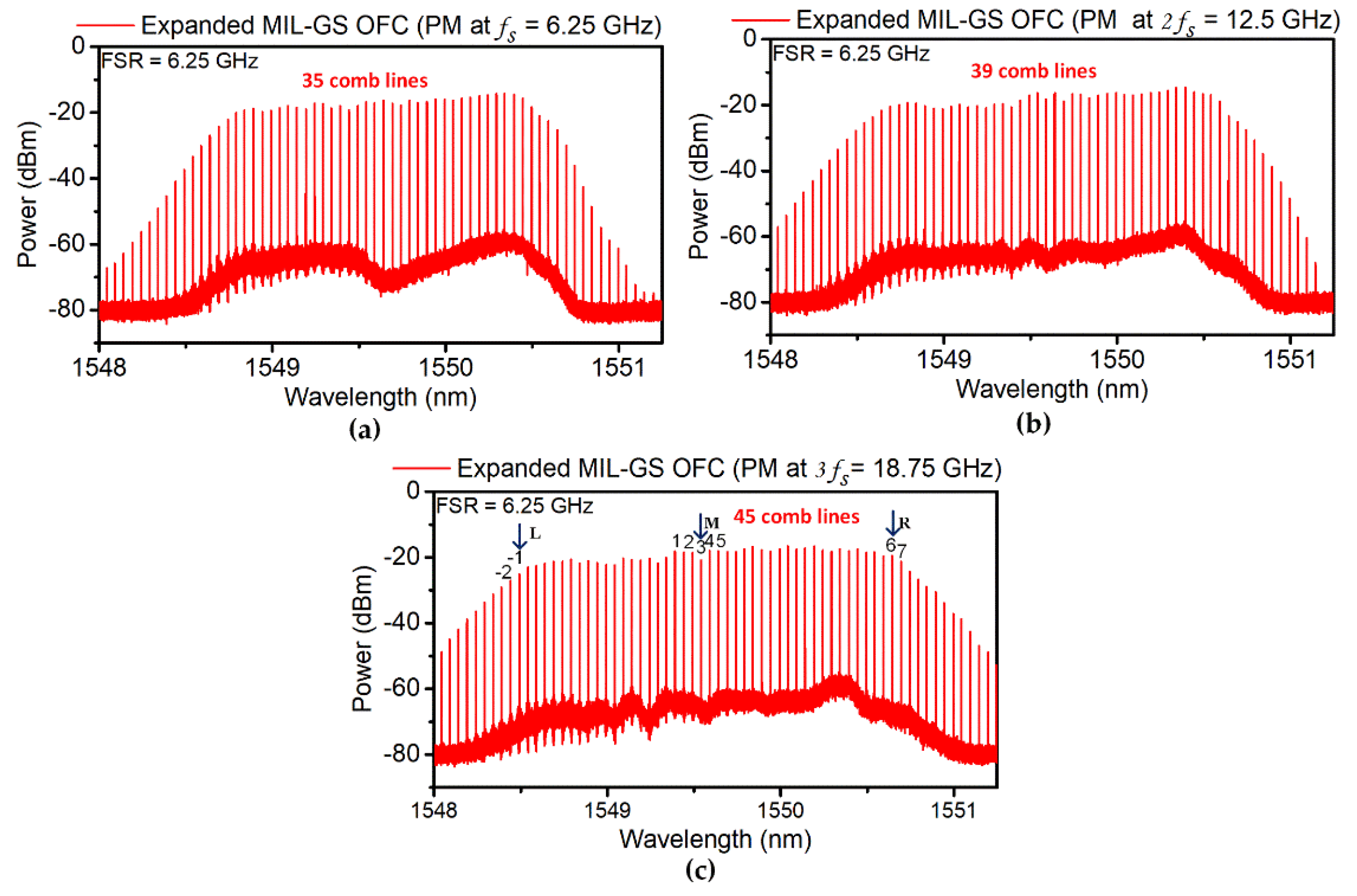
3.1.1. Comb Expansion

Figure 4a–c illustrates the phase modulator-induced comb expansion of the MIL-GS OFC, when the PM is driven at the fundamental and multiples of the FSR (6.25, 12.5, and 18.75 GHz). When driven at the fundamental frequency, 35 comb lines (comb bandwidth of 218.75 GHz) are generated, with the OCNR larger than 45 dB. The expansion factor is ~2.3 compared to the single EI-GS OFC (red spectrum, Figure 3c). The comb expansion is limited by the maximum allowable drive amplitude of the PM used. Therefore, to further increase the expansion, the PM is driven at multiples of f s with the same drive voltage. The number of comb lines increases to 39 (comb bandwidth of ~243.75 GHz), when the PM is driven at 2 f s = 12.5 GHz and 45 (~281.25 GHz bandwidth) when driven at 3 f s = 18.75 GHz. It is worth noting that only the PM drive frequency is varied, while all other conditions, such as slave laser bias, gain-switching parameters, and PM drive amplitude remain unchanged. Table 2 summarizes and quantifies the OFC expansion achieved. Overall, with the proposed MIL-GS OFC technique, the number of comb lines is increased approximately 3 times, from 15, for individual EI-GS OFC, to 45 lines for the expanded OFC.

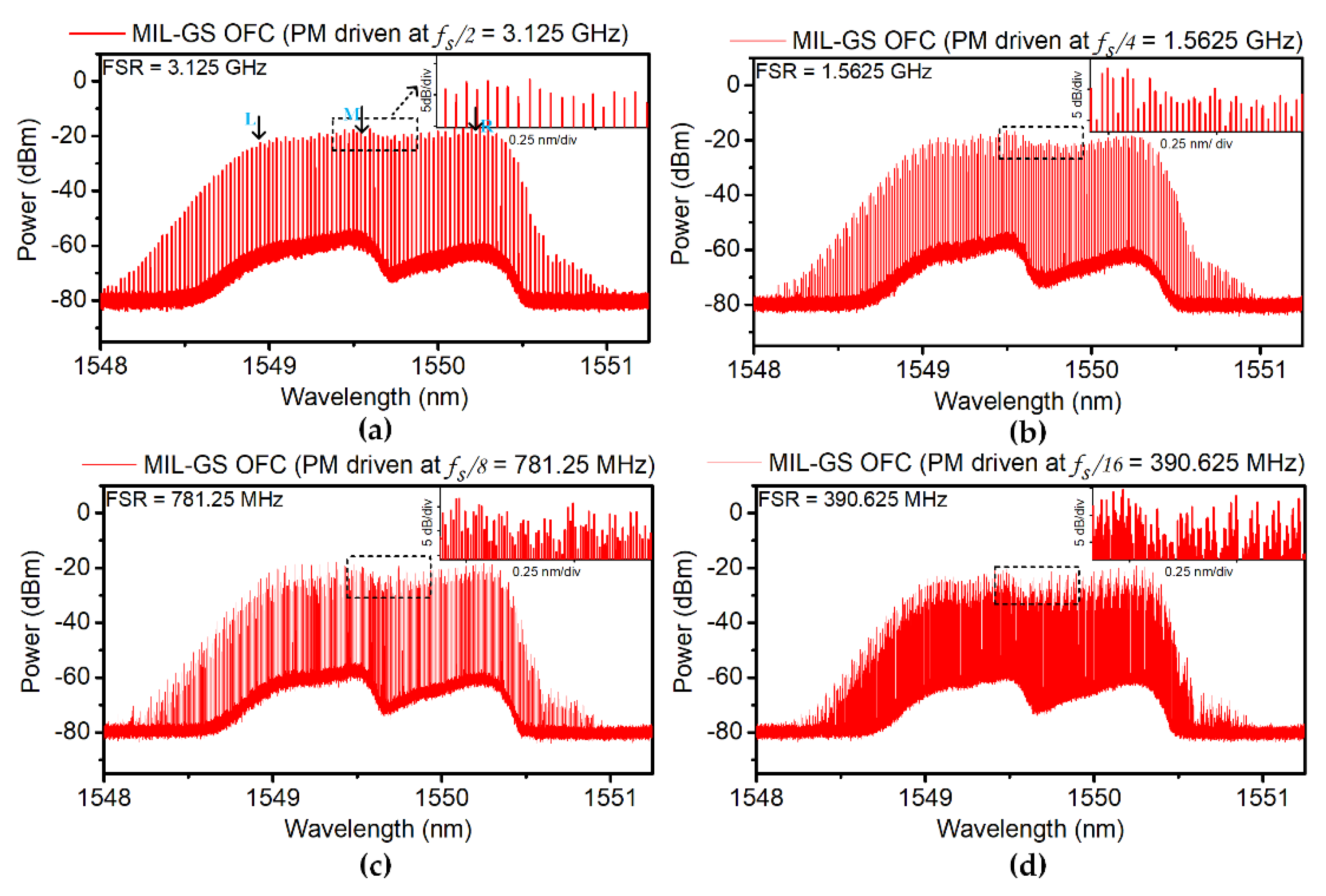
3.1.2. Comb Densification

In comb densification mode, the PM is driven at a sub-harmonic frequency of the fundamental frequency f s m , where m = 2, 4, 8, and 16. The resultant comb, with an FSR of 3.125 GHz, 1.5625 GHz, 781.25 MHz, and 390.625 MHz, is as shown in Figure 5a–d respectively. The insets within each of these figures show a magnified dotted region. Figure 5 shows clearly resolved comb tones with an OCNR ranging from ~30–45 dB (within 20 MHz OSA resolution) and a comb bandwidth ~180 GHz over the entire tuning range. The average comb output power remains constant at ~9 dBm. In comb densification mode, as illustrated by the spectra in Figure 5c,d, the spectral flatness is degraded. This degradation is worse at the lower FSRs (~10 dB from spectral peak). Two important parameters of the frequency-divided OFC are presented in Table 3. This demonstration highlights the potential of a wide FSR tunability spanning from MHz to GHz with a simplified approach and fast tuning speed. It is worth noting that the fundamental FSR can also be tuned by varying the GS frequency to the slave lasers.

3.2. Comb Line Characterization

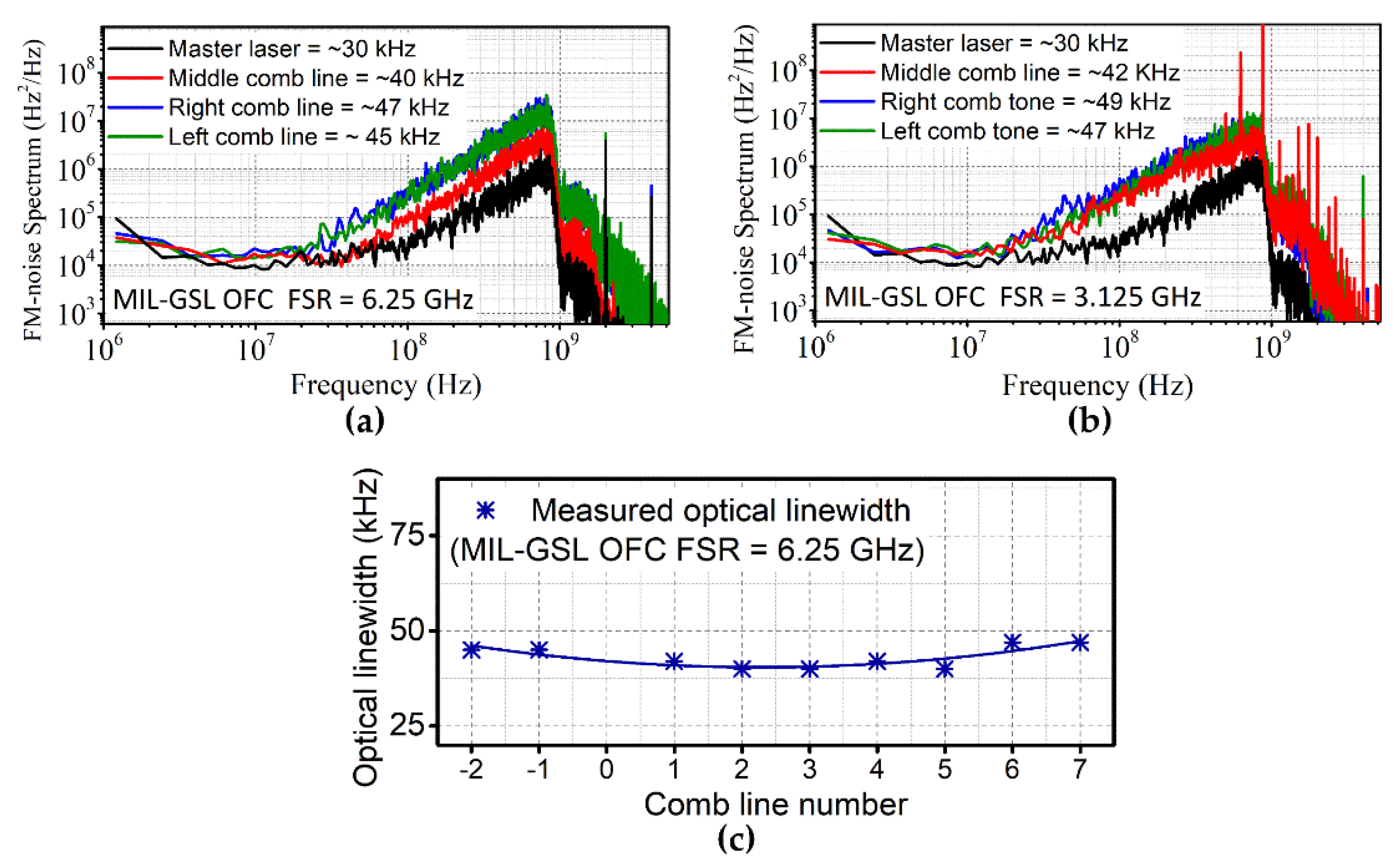
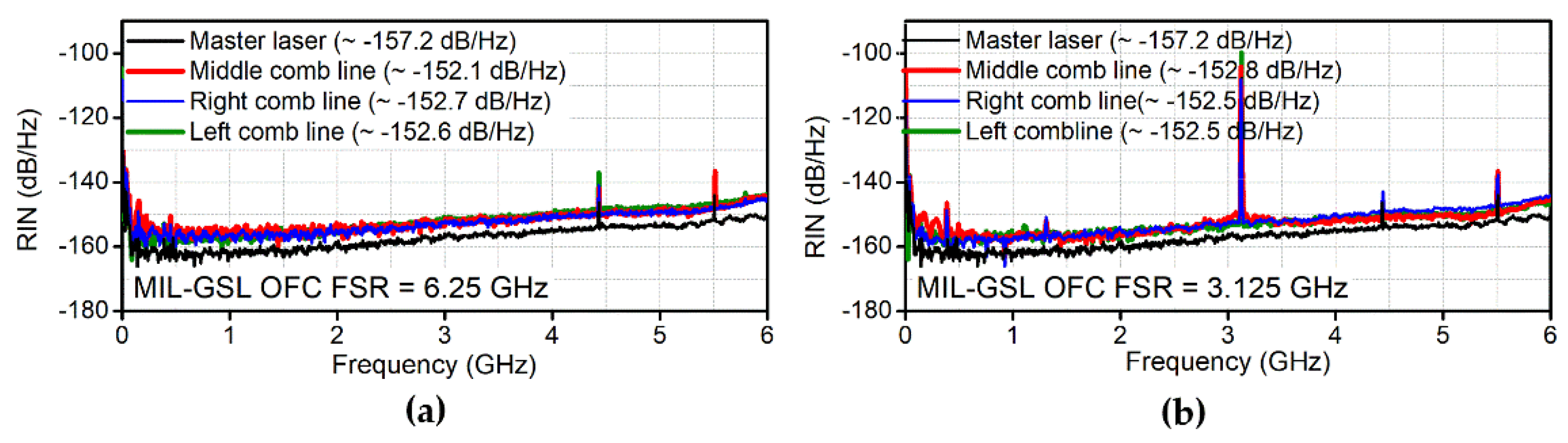
3.2.1. Phase Noise and Relative Intensity Noise

The phase noise characterization of the MIL-GS OFC lines is performed by measuring the frequency-modulation (FM) noise spectrum using the modified delayed self-heterodyne method [41]. Three different comb lines (right edge (R), middle (M), left edge (L)), as marked by the arrow in Figure 4c (Lines filtered using an optical band pass filter (Yenista Optics XTM-50) with a bandwidth of 6 GHz) and Figure 5a (Lines filtered using a semiconductor laser based active demultiplexer [42]) are filtered for phase noise analysis and compared with the master. It is worth mentioning that the 3.125 GHz FSR comb lines are filtered using a semiconductor-based active demultiplexer, which operates on the principle of optical injection locking (OIL). The principle operation and detailed characterization of such active demultiplexers are investigated in [42]. The FM noise spectrum S f ( f ) , describes the power spectral density of the instantaneous frequency fluctuation. The Lorentzian-shaped optical linewidth (δf) can be retrieved from the flat (white) FM-noise component S o , using the relationship δf = S o · π 2 [41]. The frequency range of the measurement is set to 1 GHz with a digital filter applied during the offline processing. The resultant FM noise spectrum of a 6.25 GHz comb line and the master laser are illustrated in Figure 6a. The optical linewidth of the master laser, and the middle (M), right (R) and left (L) comb lines (as marked with arrows in Figure 4c) are measured as ~30, ~40, ~47, and ~45 kHz, respectively. Furthermore, we measured optical linewidth of other comb lines (marked in numbers, Figure 4c) and found to be between 40 to 47 kHz across the entire comb, as illustrated in Figure 6c. The negligible fluctuation in the measured linewidth is due to the injection locking conditions [6]. Finally, linewidths of the OFC with the FSR of 3.125 GHz are measured to be ~42 kHz (middle), ~49 kHz (right), and ~47 kHz (left), as shown in Figure 6b. The narrow optical linewidths in all the cases indicate the efficient transfer of phase noise from the master laser to the expanded OFC.
Next, the random intensity fluctuations of the comb lines are evaluated by measuring the relative intensity noise (RIN) [43] of the same individual comb lines, as marked in Figure 4c and Figure 5a. The RIN spectra are shown in Figure 7a,b for an FSR of 6.25 and 3.125 GHz, respectively. From the figure, one can observe that all the comb lines exhibit a similar RIN profile, which is comparable with that of the master laser. The averaged RIN (from DC to 6 GHz) for the 6.25 GHz and 3.125 GHz FSRs are measured to better than −152 dB/Hz for all cases, which is slightly worse than the −157.2 dB/Hz measured RIN of the master laser. The phase noise and RIN characterization results are presented in Table 4. The results demonstrate the excellent phase and intensity noise properties of the generated OFC, satisfying requirements of various applications.

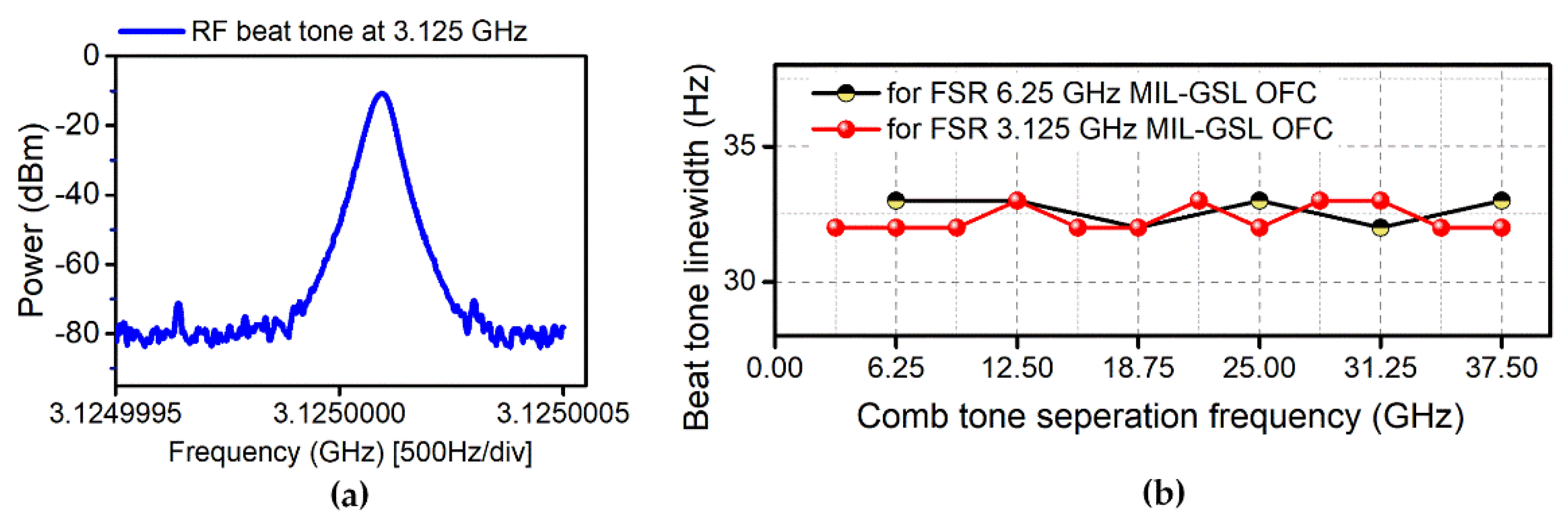
3.2.2. Phase Correlation

Finally, the phase correlation between the MIL-GS OFC lines is assessed by characterizing the resultant RF beat tone of selected pairs of comb lines. Two consecutive 3.125 GHz FSR comb lines are filtered and heterodyned on a 50 GHz photodetector to generate an RF beat tone as shown in Figure 8a. The phase correlation between the two lines cancels the optical phase noise, thus resulting in a generation of narrow beat tone with a 3 dB line width of 33 Hz (ESA setting: VBW = 30 Hz; RBW = 30 Hz). A beat tone with a line width of the order of tens of Hz reflects the phase property of RF source used for the OFC generation, thus proves a high degree of phase correlation between the comb lines. Subsequently, the measurement is repeated for pairs of comb lines separated by multiples of FSR (up to 40 GHz due to the limited bandwidth of the ESA). Consistently, a beat line width of 33 Hz is measured, as shown in Figure 8b for MIL-GS OFC with FSR of the 3.125 GHz and 6.25 GHz. The results prove a high degree of phase correlation is maintained even between tones that originated from two different GS lasers (OFC 1 and 2).

4. Conclusions

We have experimentally demonstrated a novel, highly flexible expansion scheme using mutually injection-locked two gain-switched lasers. Moreover, by incorporating a phase modulator with the proposed scheme, we showed that the number of comb lines can be further expanded, by more than 3 times, while achieving an OCNR > 40 dB. In addition, we also illustrated that, via comb densification, the FSR can easily be tuned from 6.25 GHz to 390.625 MHz. Though the comb flatness is compromised, especially operating at low FSRs (in MHzs). In the future work, phase modulator can be replaced with dual-drive MZM modulator for better expansion and flatness. The detailed comb line characterization report highlights the excellent spectral purity (narrow linewidth, low RIN, high degree of phase correlation) of the OFC lines. The proposed scheme addresses one of the main shortcomings of the EI-GSL technique, which is the limited number of comb lines/comb bandwidth and provides a simple and effective technique to generate an OFC with a tunable (from MHz to GHz) channel spacing. Finally, the entire architecture can be photonically integrated, which would enable the realization of such a scheme at reduced cost, size, and energy consumption. In summary, the proposed technique enables simple, play a crucial role in the deployment of OFCs in a wide range of applications.

Author Contributions

Conceptualization, P.D.L. and A.K.-A.; methodology, P.D.L., A.K.-A. and P.M.A.; validation, P.D.L., A.K.-A., P.M.A. and P.L.; formal analysis, P.D.L., A.K.-A. and P.M.A.; investigation, P.D.L., A.K.-A. and P.M.A.; resources, P.D.L., A.K.-A., P.M.A. and P.L.; data curation, P.D.L.; writing—original draft preparation P.D.L., P.L.; writing—review and editing, P.D.L., A.K.-A., P.M.A. and P.L.; visualization, P.D.L., A.K.-A. P.M.A. and P.L.; supervision, P.M.A. and A.K.-A.; project administration, P.M.A., A.K.-A. and P.L.; funding acquisition, P.M.A. All authors have read and agreed to the published version of the manuscript.

Funding

This research was funded by the Science Foundation of Ireland’s (SFI) career development award (15/CDA/3640), Enterprise Ireland’s DTIF (DT20180268), and SFI/RDF (13/RC/2077_P2).

Institutional Review Board Statement

Not applicable.

Informed Consent Statement

Not applicable.

Conflicts of Interest

The authors declare no conflict of interest.

References

  1. Hänsch, T.W. Nobel Lecture: Passion for precision. Rev. Mod. Phys. 2006, 78, 1297–1309. [Google Scholar] [CrossRef] [Green Version]
  2. Hall, J. Nobel Lecture: Defining and measuring optical frequencies. Rev. Mod. Phys. 2006, 78, 1279–1295. [Google Scholar] [CrossRef] [Green Version]
  3. Holzwarth, R.; Udem, T.; Hänsch, T.W.; Knight, J.; Wadsworth, W.; Russell, P. Optical Frequency Synthesizer for Precision Spectroscopy. Phys. Rev. Lett. 2000, 85, 2264–2267. [Google Scholar] [CrossRef] [PubMed] [Green Version]
  4. Minoshima, K.; Matsumoto, H. High-accuracy measurement of 240-m distance in an optical tunnel by use of a compact femtosecond laser. Appl. Opt. 2000, 39, 5512–5517. [Google Scholar] [CrossRef]
  5. Hu, H.; Da Ros, F.; Pu, M.; Ye, F.; Ingerslev, K.; Da Silva, E.P.; Nooruzzaman, M.; Amma, Y.; Sasaki, Y.; Mizuno, T. Single-source chip-based frequency comb enabling extreme parallel data transmission. Nat. Photon. 2018, 12, 469–473. [Google Scholar] [CrossRef]
  6. Zhou, R.; Huynh, T.N.; Vujicic, V.; Anandarajah, P.M.; Barry, L.P. Phase noise analysis of injected gain switched comb source for coherent communications. Opt. Express 2014, 22, 8120–8125. [Google Scholar] [CrossRef]
  7. Imran, M.; Anandarajah, P.M.; Kaszubowska-Anandarajah, A.; Sambo, N.; Poti, L. A Survey of Optical Carrier Generation Techniques for Terabit Capacity Elastic Optical Networks. IEEE Commun. Surv. Tutor. 2017, 20, 211–263. [Google Scholar] [CrossRef] [Green Version]
  8. Vujicic, V.; Anandarajah, P.M.; Zhou, R.; Browning, C.; Barry, L.P. Performance Investigation of IM/DD Compatible SSB-OFDM Systems Based on Optical Multicarrier Source. IEEE Photon. J. 2014, 6, 1–10. [Google Scholar] [CrossRef]
  9. Pfeifle, J.; Vujicic, V.; Watts, R.; Schindler, P.C.; Weimann, C.; Zhou, R.; Freude, W.; Barry, L.; Koos, C. Flexible terabit/s Nyquist-WDM super-channels using a gain-switched comb source. Opt. Express 2015, 23, 724–738. [Google Scholar] [CrossRef] [Green Version]
  10. Anandarajah, P.M.; Zhou, R.; Maher, R.; Pascual, D.M.G.; Smyth, F.; Vujicic, V.; Barry, L.P. Flexible Optical Comb Source for Super Channel Systems. In Proceedings of the Optical Fiber Communication Conference 2013, Anaheim, CA, USA, 17–21 March 2013. [Google Scholar]
  11. Supradeepa, V.R.; Long, C.M.; Wu, R.; Ferdous, F.; Hamidi, E.; Leaird, D.E.; Weiner, A.M. Comb-based radiofrequency photonic filters with rapid tunability and high selectivity. Nat. Photon. 2012, 6, 186–194. [Google Scholar] [CrossRef] [Green Version]
  12. Fortier, T.; Baumann, E. 20 years of developments in optical frequency comb technology and applications. Commun. Phys. 2019, 2, 1–16. [Google Scholar] [CrossRef]
  13. Bosco, G.; Curri, V.; Carena, A.; Poggiolini, P.; Forghieri, F. On the Performance of Nyquist-WDM Terabit Superchannels Based on PM-BPSK, PM-QPSK, PM-8QAM or PM-16QAM Subcarriers. J. Light. Technol. 2010, 29, 53–61. [Google Scholar] [CrossRef]
  14. Shao, T.; Shams, H.; Anandarajah, P.; Fice, M.J.; Renaud, C.; Van Dijk, F.; Seeds, A.; Barry, L. Phase Noise Investigation of Multicarrier Sub-THz Wireless Transmission System Based on an Injection-Locked Gain-Switched Laser. IEEE Trans. Terahertz Sci. Technol. 2015, 5, 590–597. [Google Scholar] [CrossRef] [Green Version]
  15. Alexander, J.K.; Caro, L.; Dernaika, M.; Duggan, S.P.; Yang, H.; Chandran, S.; Martin, E.P.; Ruth, A.A.; Anandarajah, P.M.; Peters, F.H.; et al. Integrated dual optical frequency comb source. Opt. Express 2020, 28, 16900–16906. [Google Scholar] [CrossRef] [PubMed]
  16. Martin, E.P.; Chandran, S.; Rosado, A.; Soderholm, E.P.; Alexander, J.K.; Peters, F.H.; Ruth, A.A.; Anandarajah, P.M. Mutually Injection Locked Gain Switched Optical Frequency Combs for Dual Comb Spectroscopy of H2S. In Proceedings of the CLEO: Applications and Technology 2020, Washington, DC, USA, 10–15 May 2020. [Google Scholar]
  17. Habruseva, T.; O’Donoghue, S.; Rebrova, N.; Kéfélian, F.; Hegarty, S.P.; Huyet, G. Optical linewidth of a passively mode-locked semiconductor laser. Opt. Lett. 2009, 34, 3307–3309. [Google Scholar] [CrossRef] [Green Version]
  18. Del’Haye, P.; Arcizet, O.; Schliesser, A.; Holzwarth, R.; Kippenberg, T.J. Full Stabilization of a Microresonator-Based Optical Frequency Comb. Phys. Rev. Lett. 2008, 101, 053903. [Google Scholar] [CrossRef] [PubMed] [Green Version]
  19. Fujiwara, M.; Kani, J.; Suzuki, H.; Araya, K.; Teshima, M. Flattened optical multicarrier generation of 12.5 GHz spaced 256 channels based on sinusoidal amplitude and phase hybrid modulation. Electron. Lett. 2001, 37, 967–968. [Google Scholar] [CrossRef]
  20. Anandarajah, P.; Maher, R.; Xu, Y.Q.; Latkowski, S.; O’Carroll, J.; Murdoch, S.G.; Phelan, R.; O’Gorman, J.; Barry, L. Generation of Coherent Multicarrier Signals by Gain Switching of Discrete Mode Lasers. IEEE Photon. J. 2011, 3, 112–122. [Google Scholar] [CrossRef]
  21. Zhou, R.; Latkowski, S.; O’Carroll, J.; Phelan, R.; Barry, L.; Anandarajah, P. 40 nm wavelength tunable gain-switched optical comb source. Opt. Express 2011, 19, B415–B420. [Google Scholar] [CrossRef]
  22. Shao, T.; Zhou, R.; Pascual, M.D.G.; Anandarajah, P.M.; Barry, L.P.; Pascual, D.; Prince, A. Integrated Gain Switched Comb Source for 100 Gb/s WDM-SSB-DD-OFDM System. J. Light. Technol. 2015, 33, 3525–3532. [Google Scholar] [CrossRef]
  23. Venkatasubramani, L.N.; Lin, Y.; Browning, C.; Vijay, A.; Smyth, F.; Koilpillai, D.; Venkitesh, D.; Barry, L. CO-OFDM for Bandwidth-Reconfigurable Optical Interconnects using Gain Switched Comb. OSA Contin. 2020, 3, 2925–2934. [Google Scholar] [CrossRef]
  24. Ahmad, S.T.; Lakshmijayasimha, P.D.; Anandarajah, P.M.; Kaszubowska-Anandarajah, A. 200 Gb/s Short Reach Transmitters Based on Optical Frequency Combs. In Proceedings of the 2020 22nd International Conference on Transparent Optical Networks (ICTON), Bari, Italy, 19–23 July 2020; pp. 1–2. [Google Scholar]
  25. Pascual, M.D.G.; Vujicic, V.; Braddell, J.; Smyth, F.; Anandarajah, P.; Barry, L. Photonic Integrated Gain Switched Optical Frequency Comb for Spectrally Efficient Optical Transmission Systems. IEEE Photon. J. 2017, 9, 1–8. [Google Scholar] [CrossRef]
  26. Quevedo-Galán, C.; Durán, V.; Rosado, A.; Perez-Serrano, A.; Tijero, J.M.G.; Esquivias, I. Gain-switched semiconductor lasers with pulsed excitation and optical injection for dual-comb spectroscopy. Opt. Express 2020, 28, 33307–33317. [Google Scholar] [CrossRef] [PubMed]
  27. Weng, W.; Kaszubowska-Anandarajah, A.; He, J.; Lakshmijayasimha, P.D.; Lucas, E.; Liu, J.; Anandarajah, P.M.; Kippenberg, T.J. Gain-switched semiconductor laser driven soliton microcombs. Nat. Commun. 2021, 12, 1–9. [Google Scholar] [CrossRef]
  28. Hei, K.; Kaszubowska-Anandarajah, A.; Martin, E.P.; Shi, G.; Anandarajah, P.M.; Bhattacharya, N. Absolute distance measurement with a gain-switched dual optical frequency comb. Opt. Express 2021, 29, 8108–8116. [Google Scholar] [CrossRef]
  29. Zhou, R.; Anandarajah, P.; Pascual, M.D.G.; O’Carroll, J.; Phelan, R.; Kelly, B.; Barry, L. Monolithically Integrated 2-Section Lasers for Injection Locked Gain Switched Comb Generation. In Proceedings of the Optical Fiber Communication Conference 2014, San Francisco, CA, USA, 9–13 March 2014. [Google Scholar]
  30. Pascual, M.D.G.; Vujicic, V.; Braddell, J.; Smyth, F.; Anandarajah, P.M.; Barry, L.P. InP photonic integrated externally injected gain switched optical frequency comb. Opt. Lett. 2017, 42, 555–558. [Google Scholar] [CrossRef]
  31. Hammad, M.N.; Lakshmijayasimha, P.D.; Kaszubowska-Anandarajah, A.; Anandarajah, P.M. Photonically integrated gain-switched lasers for optical frequency comb generation. Microw. Opt. Technol. Lett. 2021, 63, 2219–2226. [Google Scholar] [CrossRef]
  32. Rosado, A.; Pérez-Serrano, A.; Tijero, J.M.G.; Valle, Á.; Pesquera, L.; Esquivias, I. Enhanced optical frequency comb generation by pulsed gain-switching of optically injected semiconductor lasers. Opt. Express 2019, 27, 9155–9163. [Google Scholar] [CrossRef] [PubMed]
  33. Prior, E.; de Dios, C.; Criado, R.; Ortsiefer, M.; Meissner, P.; Acedo, P. Expansion of VCSEL-Based Optical Frequency Combs in the Sub-THz Span: Comparison of Non-Linear Techniques. J. Light. Technol. 2016, 34, 4135–4142. [Google Scholar] [CrossRef] [Green Version]
  34. Lakshmijayasimha, P.D.; Kaszubowska-Anandarajah, A.; Martin, E.P.; Landais, P.; Anandarajah, P.M. Expansion and phase correlation of a wavelength tunable gain-switched optical frequency comb. Opt. Express 2019, 27, 16560–16570. [Google Scholar] [CrossRef]
  35. Pascual, M.D.G.; Anandarajah, P.; Zhou, R.; Smyth, F.; Latkowski, S.; Barry, L. Cascaded Fabry-Pérot lasers for coherent expansion of wavelength tunable gain switched comb. In Proceedings of the 40th European Conference on Optical Communications (ECOC 2014), Cannes, France, 21–25 September 2014; pp. 1–3. [Google Scholar]
  36. Pascual, M.D.G.; Zhou, R.; Smyth, F.; Shao, T.; Anandarajah, P.M.; Barry, L. Dual mode injection locking of a Fabry-Pérot laser for tunable broadband gain switched comb generation. In Proceedings of the European Conference on Optical Communication (ECOC), Valencia, Spain, 27 September–1 October 2015; pp. 1–3. [Google Scholar]
  37. Delmade, A.; Krstić, M.; Browning, C.; Crnjanski, J.; Gvozdić, D.; Barry, L. Power efficient optical frequency comb generation using laser gain switching and dual-drive Mach-Zehnder modulator. Opt. Express 2019, 27, 24135–24146. [Google Scholar] [CrossRef]
  38. Yang, W.-Y.; Xia, G.-Q.; Jiang, Z.-F.; Deng, T.; Lin, X.-D.; Jin, Y.-H.; Xiao, Z.-Z.; Yue, D.-Z.; Hu, C.-X.; Cui, B.; et al. Experimental Investigation on Wideband Optical Frequency Comb Generation Based on a Gain-Switched 1550 nm Multi-Transverse Mode Vertical-Cavity Surface-Emitting Laser Subject to Dual Optical Injection. IEEE Access 2020, 8, 170203–170210. [Google Scholar] [CrossRef]
  39. Herbert, C.; Anandarajah, P.; Perry, P.; Jones, D.; Kaszubowska-Anandarajah, A.; Barry, L.; Kelly, B.; O’Carroll, J.; O’Gorman, J.; Rensing, M.; et al. Discrete mode lasers for communication applications. IET Optoelectron. 2009, 3, 1–17. [Google Scholar] [CrossRef]
  40. O’Duill, S.P.; Zhou, R.; Anandarajah, P.; Barry, L. Analytical Approach to Assess the Impact of Pulse-to-Pulse Phase Coherence of Optical Frequency Combs. IEEE J. Quantum Electron. 2015, 51, 1–8. [Google Scholar] [CrossRef]
  41. Huynh, T.N.; Nguyen, L.; Barry, L. Phase Noise Characterization of SGDBR Lasers Using Phase Modulation Detection Method with Delayed Self-Heterodyne Measurements. J. Light. Technol. 2013, 31, 1300–1308. [Google Scholar] [CrossRef]
  42. Lakshmijayasimha, P.D.; Kaszubowska-Anandarajah, A.; Martin, E.P.; Hammad, M.N.; Landais, P.; Anandarajah, P.M. Characterization of a multifunctional active demultiplexer for optical frequency combs. Opt. Laser Technol. 2021, 134, 106637. [Google Scholar] [CrossRef]
  43. Relative Intensity Noise of Distributed Feedback Lasers, Application Note. Available online: https://www.eagleyard.com/fileadmin/downloads/documents/eyP_App_Note_RIN__1-6.pdf (accessed on 13 May 2020).
Figure 1. (a) Illustrative diagram of proposed MIL-GS OFC generation, expansion and comb densification scheme. (be) are the line graph of the operational principle.
Applsci 11 07108 g001
Figure 2. Experimental setup of the proposed MIL-GS OFC generation scheme. Here, RF sig.: radio frequency signal source; RF amp: amplifier; CIR: circulator; PS: phase shifter; ODL: optical delay line; PC: polarization controller; PM: phase modulator; f s : free spectral range (FSR); OSA: optical spectrum analyzer.
Applsci 11 07108 g002
Figure 3. Optical spectra of (a) slave lasers in CW state; (b) Master and GS slave 1 and 2; (c) MIL-GS OFC 1 and 2; (d) Expanded OFC (combined MIL-GS OFC 1 and 2).
Applsci 11 07108 g003
Figure 4. Optical spectra of expanded MIL-GS OFC, PM driven at (a) 6.25; (b) 12.5, and (c) 18.75 GHz. The arrows (L: left, M: middle, R: right) and numbered tones are filtered for phase noise analysis.
Applsci 11 07108 g004
Figure 5. Optical spectra of comb densification MIL-GS OFC with FSR of (a) 3.125 GHz; (b) 1.5625 GHz; (c) 781.25 MHz; (d) 390.625 MHz. The insets depict a zoom in on the dotted region (5 dB/div scale).
Applsci 11 07108 g005
Figure 6. FM noise spectrum for MIL-GS OFC lines at FSR of (a) 6.25 GHz; (b) 3.125 GHz; (c) plot of measured optical linewidths of different comb tone (FSR = 6.25 GHz).
Applsci 11 07108 g006
Figure 7. Relative intensity noise measurements for MIL-GS OFC of FSR (a) 6.25 GHz; (b) 3.125 GHz.
Applsci 11 07108 g007
Figure 8. (a) An electrical spectrum of the resultant beat tone at 3.125 GHz; (b) RF beat tone linewidth for OFC with FSR of 6.25 GHz and 3.125 GHz (ESA resolution 30 Hz).
Applsci 11 07108 g008
Table 1. Survey summary of GSL expansion demonstrations.
Ref.Key Expansion
Component
OFC
FSR
Expansion FactorPhotonic
Integration
Demonstration/Comments
[21]FP + phase modulator10 GHz~ 2Yes40 nm wavelength tunability; limited expansion
[20]HNLF + DCF10.7 GHz>3NoWide comb generation; complexity and stability issues
[35]Cascaded GS FP lasers10 GHz~2Yes20 nm wavelength tunability; limited expansion; low OCNR
[36]Dual-mode FP IL6.25 GHz>2YesSimple; 30 nm wavelength tunability; poor flatness; low OCNR
[38]VCSEL HNLF + DCF + Modulator5.2 GHz~3 NoWide comb generation; complexity; stability issues; low OCNR
[34]Parallel cascaded FP + SOA 6.25 GHz>3Yes Wide comb generation; amplified output power; 30 nm wavelength tunability; complex
[37]Dual-drive MZM9.5 GHz>1.5 PartiallySimple; low drive voltage; limited expansion
[38]VCSEL + dual mode injection locking2.5 GHz~2YesSimple; limited expansion
This workMutual injection locking + phase modulator6.25 GHz~3YesWide comb generation; simple; FSR tunability from 390 MHz to 6.25 GHz
Table 2. Summary of the OFC expansion at FSR of 6.25 GHz.
OFC TypeNumber of Lines
(5 dB from Peak)
Comb
Bandwidth
Expansion
Factor
Individual GSL OFC15~93.7 GHz--
Combined MIL-GSL OFC27~168.75 GHz1.8
MIL OFC + PM (at 6.25 GHz)35~218.75 GHz2.3
MIL OFC + PM (at 12.5 GHz)39~243.75 GHz2.6
MIL OFC + PM (at 18.75 GHz)45~281.25 GHz3
Table 3. Summary of the MIL-GS OFC comb densification.
MIL-GSL OFC
FSR
OCNR
(Tone at ~1550 nm)
Number of Lines
(5 dB from Peak)
6.25 GHz5027
3.125 GHz4558
1.5625 GHz~42~113
781.25 MHz~38~214 (within 10 dB)
390.625 MHz~33~453 (within 10 dB)
Table 4. Summary of the MIL-GSL OFC phase noise and RIN characterization.
Phase NoiseRIN
6.25 GHz3.125 GHz6.25 GHZ3.125 GHz
Master laser~30 kHz~30 kHz~−157.2 dB/Hz ~−157.2 dB/Hz
Comb line (middle)~40 kHz~42 kHz~−152.1 dB/Hz~−152.8 dB/Hz
Comb line (right)~47 kHz~49 kHz~−152.7 dB/Hz~−152.5 dB/Hz
Comb line (left)~45 kHz~47 kHz~−152.6 dB/Hz~−152.5 dB/Hz
Publisher’s Note: MDPI stays neutral with regard to jurisdictional claims in published maps and institutional affiliations.

