Article

Enhancing Design for Additive Manufacturing Workflow: Optimization, Design and Simulation Tools

by
Nicolas Alberto Sbrugnera Sotomayor
,
Fabrizia Caiazzo
and
Vittorio Alfieri
*
Department of Industrial Engineering, University of Salerno, Via Giovanni Paolo II 132, 84084 Fisciano, Italy
*
Author to whom correspondence should be addressed.
Appl. Sci. 2021, 11(14), 6628; https://doi.org/10.3390/app11146628
Submission received: 24 June 2021 / Revised: 13 July 2021 / Accepted: 16 July 2021 / Published: 19 July 2021
(This article belongs to the Special Issue Design for Additive Manufacturing: Methods and Tools)

Abstract

:
In the last few decades, complex light-weight designs have been successfully produced via additive manufacturing (AM), launching a new era in the thinking–design process. In addition, current software platforms provide design tools combined with multi-scale simulations to exploit all the technology benefits. However, the literature highlights that several stages must be considered in the design for additive manufacturing (DfAM) process, and therefore, performing holistic guided-design frameworks become crucial to efficiently manage the process. In this frame, this paper aims at providing the main optimization, design, and simulation tools to minimize the number of design evaluations generated through the different workflow assessments. Furthermore, DfAM phases are described focusing on the implementation of design optimization strategies as topology optimization, lattice infill optimization, and generative design in earlier phases to maximize AM capabilities. In conclusion, the current challenges for the implementation of the workflow are hence described.

1. Introduction

According to ISO/ASTM standards, additive manufacturing (AM) is defined as the process of joining materials, generally by layer-by-layer approach, to produce parts starting from digital representations [1]. Continuous development of metal AM technologies, such as directed energy deposition (DED) or laser powder bed fusion (LPBF), yield new industrial design perspectives due to several technology benefits.
Indeed, the main AM advantages include: the possibility to manufacture complex internal part-functionalities like cooling channels in turbine blades [2], lattice and gyroids structures in medical implants [3,4]; low buy-to-fly ratio [5]; consolidate part assemblies into fewer components [6]; achieve mechanical properties as tensile and yield strength comparable to bulk materials [7]; and high part-customization. Consequently, AM becomes an economically suitable technology where low-production volumes or customizable production on-demand are required [8].
However, there are still drawbacks related to the complex thermo-physical phenomena involved: repeated cycles of rapid cooling of the melted pool generate anisotropy depending on building direction [9]; control of printing parameters is required to prevent physical problems of balling, key-hole formation and lack of fusion [10]; residual porosity affects end-parts mechanical properties [11]; energy consumption is high to melt or sinter the metal powder [12]; and low surface quality occurs due to layer-by-layer deposition [13], thus reducing fatigue life [9]. Moreover, volumetric restrictions on part size [14], time-consuming jobs and lack of standard certifications for certain industries as aerospace, are still considered limitation factors [15].
In the traditional design for manufacturing (DFM) process, it is required to find a design solution that minimizes manufacturing, assembly and logistic costs [16]. To take into consideration these objectives with the unique AM technology capabilities (e.g., part consolidation, design freedom and highly part-customization), the design for additive manufacturing (DfAM) allows rethinking the whole design process from the digital database to the final printed part. In addition, to take into consideration the geometric printing technology limitations, DfAM guidelines are provided, based on empirical analysis depending on the material, printing parameters and manufacturing technology. Namely, it’s possible to recognize [17]: critical angle of self-supported faces, minimum diameters for unsupported holes, optimal position on the building plate, maximum allowable aspect ratio of thin columns, minimum printable wall thickness and minimum feature size. To reduce manufacturing costs related to energy consumption, printing time and post-processing, parts should be designed with minimum support generation. Indeed, supports are usually required for overhanging sections, to prevent collapse during building. However, for metal AM, supports are crucial and cannot be removed at all due to the high-stress gradient generated during printing. In this case, supports act as heat transfer structures preventing excessive distortions and residual stresses.
Initially, the guided-design process performs post-processing checks, while recent advancements on software platforms allow predicting thermal effects and mechanical performance in earlier design phases. However, the physical and manufacturing limitations mentioned above mean that the DfAM process workflow involves several stages to maximize printing capabilities and ensure correct manufacturability. In addition, the process is considered a challenging task to perform, since computer-aided design (CAD), computer-aided engineering (CAE), and computer-aided manufacturing (CAM) must be evaluated at different abstraction levels requiring full design, simulation and manufacturing knowledge.
Engineering fields, such as automotive, aerospace, robotics, and medical prosthesis, often require the design of lightweight structures for improving the energy efficiency of moving systems enhancing the physical performance of analysis. To achieve this goal, structural optimization is used as a suitable design framework based on mathematic formulations consisting of coupling physic system responses such as stress, natural frequencies, compliance, or displacements with deterministic or stochastic algorithms to find an optimal layout material by an iterative process. This global definition includes [18]: sizing, shape, and topology optimization (TO). Sizing optimization aims at determining the optimum cross-sectional area of structural members, while shape optimization focuses on the optimum boundary domain shape [19]. Particular attention has been addressed in the industry and academia on TO strategies due to more design flexibility generating internal voids in the design domain. In general, TO algorithms result in complex geometries, which are not common by traditional thinking, mainly mimicking nature designs [20]. As a result, AM became the perfect manufacturing technology to be coupled with TO capabilities, and hence improve the DfAM workflow.
In this frame, this manuscript aims to describe the main DfAM workflow assessments, focusing on suitable optimization, design, and simulation tools to reduce the number of required design evaluations. Particular attention was addressed on including topology optimization, lattice infill optimization and generative design in earlier design phases to obtain high-performance parts that could be properly produced via AM. In this field, the main theory behind the optimization algorithm used in commercial software is hence described.

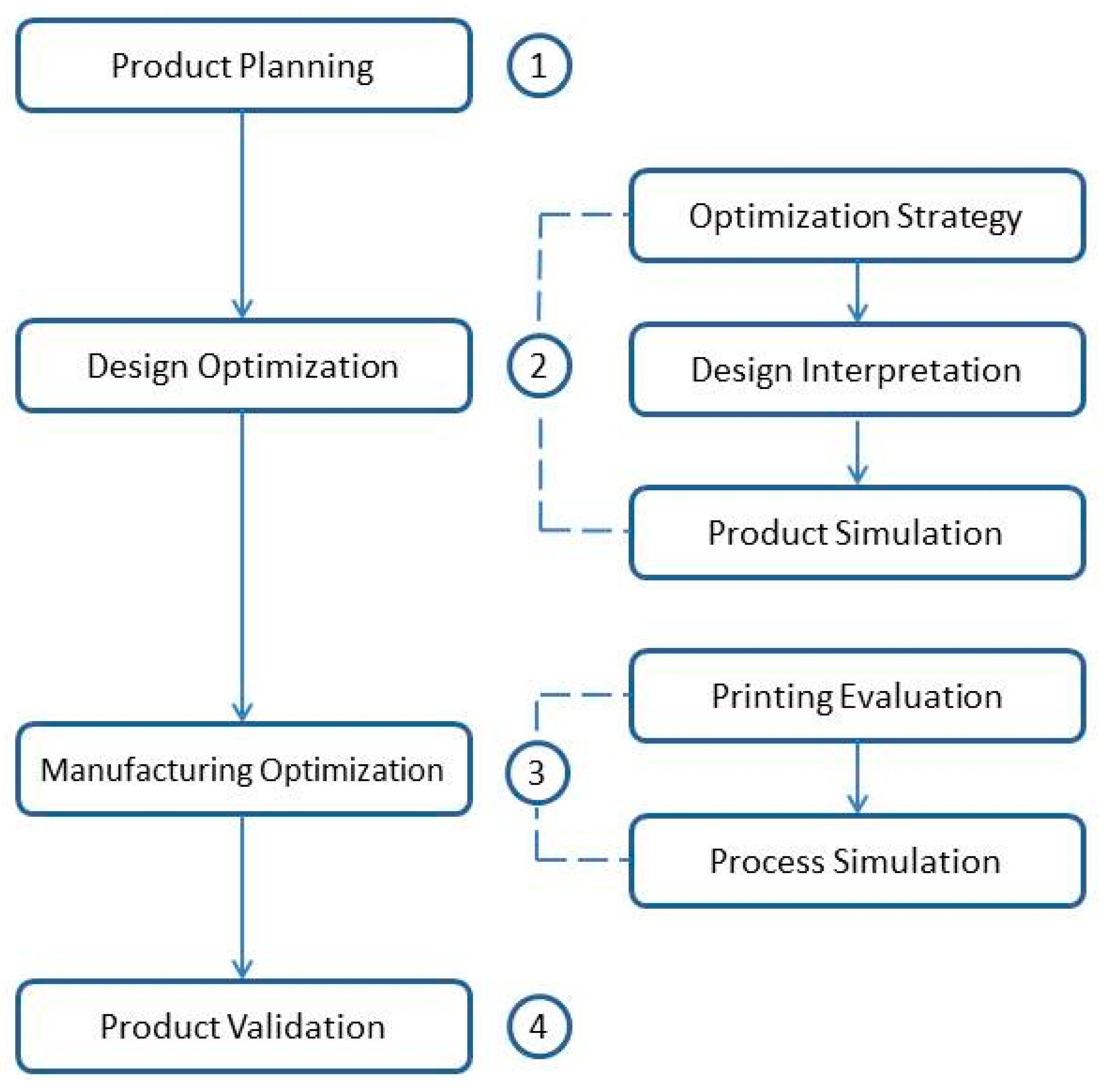
2. Holistic DfAM Workflow

As suggested in Figure 1, from a macro point of view, traditional DfAM holistic workflow involves four main phases described by local tasks to be performed [21]: product planning, design optimization, manufacturing optimization and product validation. Product planning activities include modelling preparation of base design, definition of objectives and constraints, finite element analysis and feasibility analysis to include a structural optimization strategy. Design optimization involves an iterative process of: design optimization strategy; design interpretation of optimized results and product simulation. Manufacturing optimization actions imply printing modeling with support generation, optimization of support structures, and additive process simulation. The last phase involves part manufacturing, post-processing, performance validation via mechanical testing and quality inspection.
Design and manufacturing optimization represents the digital phases of the DfAM workflow, they are characterized by several design iterations to validate the design proposals. As described in [22], an automatic approach is required with suitable self-parametric design interpretation, coupling AM simulation models with manufacturing settings, cost evaluation and support structures. However, this level of automation was not yet reached. Instead, software platforms as 3DExperience (Dassault Systemes, Velizy-Villacoublay, France) and Ansys (Ansys Inc., Canonsburg, USA) integrates all the required computer aided tools such as geometry preparation, topology optimization, FEM validation, additive preparation and AM process simulation in the same software interface. The main advantage offered by this approach is to facilitate interchange data and manipulation of intermediate results [21].

3. Product Planning

Once a candidate part is selected to perform the DfAM process, a CAD file must be created for FEM analysis, to predict the real performance based on the domain distribution of physical responses such as temperature, stresses, displacements and modal frequencies of vibration. Based on this, a qualitative analysis is available for material distribution and feasibility to include a structural optimization strategy. Additionally, the initial safety factor found from the maximum response values and the admissible material resistance enables the viability of proposing any change in material design [23].
In some cases, where a CAD model is not available for starting the process [24], computer-aided reverse engineering (CARE) is performed [25]: the computer model is obtained by surface cloud points through measurements of the object with laser-based scanner or coordinate measure machines. In this operation, a surface representation results in digital formats as standard triangulation language (STL) [26], mesh-part file and graphics exchange specification (IGES). Then, CAD file is obtained with adequate modeling tools offered in software platforms.
This phase is also characterized by the definition of design and non-design domains for applying the structural optimization process. One of the main features of mathematical-based optimization is that solutions are very sensitive to the defined initial domains, with a huge impact on mechanical performance in the simulation validation process [27]. To maximize optimization exploration capabilities to find the optimal material distribution, the definition of a vast design domain is recommended considering space limitation for part-assembly. Additionally, at this stage, to reduce the number of required iterations in the manufacturing-phase optimization, a suitable printing direction is decided, based on the size of the building chamber, with possible additional restrictions via the expedient of frozen regions [28].

4. Optimization Strategy

This phase is focused on solving the selected structural optimization process and validating the performance of the proposed design. Given a design domain, boundary constraints and loading conditions, TO describes solid mathematical method implemented through computer-aided engineering (CAE) software. The method allows finding the optimum material layout that maximizes or minimizes an objective function representing a physic response of the system subjected to constraints. In general, real systems are subjected to multiple loading conditions requiring the definition of a multi-objective criteria optimization [29]. One common approach is to solve the multi-objective problem with a single scalar function by associating weighted factors to the different loading cases [30]. This converts the problem into the so-called Pareto-optimality describing a frontier of admissible optimal solutions. In [31] a 199-line Matlab code for tracing the Pareto optimal frontier is proposed: interestingly, no sub-objective can be improved without diminishing another with the main limitation to find a priori adequate values of weight factors [32].
Given this background, TO could be applied to a vast range of physics problems, with the conditional enforcement that the partial differential equation (PDE) of analysis might be reliably discretized and modelled using finite element method (FEM), boundary element method (BEM), finite volume method (FVM) or other domain discretization schemes [33]. Besides classic static structural analysis, the process can be applied to fluid dynamics [34], heat transfer [35], electromagnetism [36], acoustic [37] and Multiphysics combinations between them [38]. In this manner, it is possible to associate a wide number of objectives and constrains formulations including compliance, stress, frequency, displacements, Eigen frequencies, reaction forces, moment of inertia, critical buckling load, mass or volume. Typical optimization tasks for static structural problems are: compliance minimization that is equivalent to stiffness maximization with volume constraint [39]; volume minimization with stress constraint [40]; and minimizing displacement under volume constraint [41].
The global classification of TO methods is based on the fact that the optimization process requires or does not calculate the gradient information of the objective functions. Therefore, two main groups are defined: deterministic (gradient-based) and stochastic (heuristic) methods; the later are inspired by nature and gradient calculus is not required. Gradient-based methods include homogenization, density interpolation schemes as SIMP (Solid Isotropic Material with Penalization) or RAMP (Rational Approximation of Material Properties), and level set methods. Stochastic methods include metaheuristic algorithms like evolutionary approaches as Genetic Algorithm (GA), ESO, BESO and bioinspired algorithms like particle swarm intelligence, human base (tabu-search) and physical-based (Colliding bodies). The reader is kindly referred to [42] for an in-depth review of these TO methods and their numerical formulation. All of the proposed algorithms have in common the definition of a discretized domain and the necessity of implement filtering techniques to ensure smooth convergence and mesh-independency results. Differences between consists in purely mathematical definition with continuous or discrete variables, linear or non-linear programming, heuristic or mathematical derivation, local or global length scale control with implicit-explicit means.
Nowadays, software platforms allow applying several optimization strategies for maximizing performance and obtaining lightweight structures that are suitably produced by AM technologies. In this manuscript, different TO approaches are presented: traditional gradient-based sequence with density interpolation schemes, infill optimization with lattice structures and the innovative generative design approach. All of these are significantly appropriate in the frame of DfAM.

4.1. Numerical Instabilities of TO

Main numerical instabilities of TO problems are defined in [43] as checkerboard patterns, mesh dependence and local minima solution. The checkerboard pattern describes a periodic pattern of low and high values for the design variable arranged as a checkerboard. This result is undesirable since the material layout is not appropriate. It was shown in [44] that a finite discretized domain with a patch arrangement of average density of ½ provides artificial high stiffness when applied to the TO for minimizing compliance. Additionally, [45] concludes that this numerical instability is caused by FEM where the equilibrium equations are only referred to element nodes. Moreover, the use of lower-order elements promotes checkerboard patterns, while higher-order discretization schemes reduce the global effect. In this case, finite-volume theory accomplishes the task to eliminate checkerboards.
The mesh dependence problem appears when mesh-refinement of the design domain results in different topology instead of better description for boundaries [46]. The solution to both checkerboard-patterns and mesh dependency is the regularization of the domain design by filtering techniques. From the wide spectrum of filtering schemes the most valuable for easy implementation and efficiency are density and sensitivity filters [47]. In the former, the element density is calculated as a weighted average of the neighborhood elements included in the characteristic filter radius; in the latter, standard calculus of element density is used to calculate a weighted average of the neighborhood sensitivities [48].
Nerveless, it is worth noting that regularization schemes fail in mitigating solutions with a grayscale interface. To obtain pure black and white designs, with a minimum interface, post-processing on the design domain is required through projection schemes like the Heaviside threshold [49]. For example, commercial software Comsol Multiphysics (Comsol Inc., Stockholm, Sweden) englobes filtering and projection schemes in the so-called three-field density representation [50]. The chain of transformations starts from the design domain, then a PDE density filter scheme is applied and the last operation includes a Heaviside projection function to improve the contour boundaries.
Solving TO problems with penalized interpolation schemes results in non-convex problems, hence obtaining local minima solutions [51]. To prevent this, continuation schemes are typically employed on material and filter parameters. For the SIMP scheme, the continuation strategies solve an initial convex problem, characterized with uniqueness solution, with low value of the penalization parameter. This solution is used as input for consecutive cycles, where this parameter is increased in steps until arriving at adequate values.

4.2. Gradient-Based TO

Available commercial software as Altair Hyperworks (Altair Engineering, Troy, MI, USA) [52], SolidWorks (Dassault Systemes, Velizy-Villacoublay, France), MSC (MSC Software Corporation, Newport Beach, CA, USA) [53], Comsol Multiphysics (Comsol Inc., Stockholm, Sweden) [54], Ansys (Ansys Inc., Canonsburg, PA, USA) and Abaqus (Abaqus Inc., Velizy-Villacoublay, France) solves the TO problem by using the gradient-based density approach, associated to the density interpolation scheme method SIMP or power-law approach. The density approach is characterized by a design variable assigned to discretized elements representing an artificial density of material [55]. This variable ranges from 0 to 1 in the case of void elements or solid material, respectively. In general, platforms provide as objective function minimizing compliance to find the maximum stiffness layout material distribution, aiming to reduce the computing complexity of gradient-based algorithms [56]. Alternatively, other optimization algorithms are available through MATLAB or Python codes and integrated into FEM commercial software [57].
The solution of gradient-based TO strategy is found through an iterative process called nested-formulation [58]. The iterative loop consists of five main steps [59]: FEM analysis, sensitivity analysis, filtering techniques, optimality algorithm updating design variables and post-processing.
In general, the stiffness matrix structure and the displacement field are found via FEM. Then, the density design variables are assigned into the design domain as constants for each finite element. By using a sensitivity analysis, the process calculates the partial derivatives of the objective function concerning the value of the design variable, at each element. For the particular case of compliance objective function, the derivative is always negative [60], thus indicating that increasing element-density yields a decrease of the overall compliance, and a stiffer structure. Aiming at reducing the numerical instabilities, the next step is applying density or sensitivity filtering techniques to impose a length-scale restriction on the design domain, thus limiting the spectrum of possible feasible solutions. The following phase uses an optimality algorithm method like optimality criteria (OC) [61] or the method of moving asymptotes (MMA) [62] that approximate the value of the objective function by using the sensitivity results. In this manner, the optimization task is divided into sub-problems so that solving is more efficient. The last step consists of updating the design variable values. The cycle is repeated until numerical convergence. Additional post-processing via projection filters might be required to improve contour boundaries.

4.3. SIMP Approach

One efficient strategy to solve the gradient-based TO formulation consists in a continuous representation of the density variable associated with some form of penalty that steers intermediate solutions into discrete values. In the SIMP approach, a penalization parameter is used to penalize intermediate values of the design variable so they became unfavorable in the sense that the stiffness obtained is small compared to the required material volume [46]. Then, the design variable is multiplied onto physical quantities as stiffness, cost or conductivity to evaluate the performance of the material distribution in the FEM analysis.
In density interpolation schemes the physical interpretation of greyscale or intermediate values is represented by the homogenization method correlated to porous composite materials [58]. Low values of the penalization parameter cause too much greyscale so the optimum material distribution is improperly defined. On the other hand, high values, lead to a fast convergence solution into local minima, thus reducing the probability to obtain a global optimum distribution. Adequate values are recommended from 3 to 5 based on the verification of composite Hashin–Shtrikman bounds [58].
An evolution of the method has been suggested with the introduction of a minimum stiffness value [47] that prevents singularity problems of the stiffness matrix when computing equilibrium equations. In addition, this method presents the advantage of their easy generalization to many filtering techniques. This approach was efficiently introduced in the 88-lines Matlab code for minimizing compliance [63].

4.4. Lattice Infill Optimization

Lattice structures are very attractive for industrial lightweight applications [64]. Namely, the hip implant prosthesis is optimized with internal lattice infill to reduce the physical phenomenon of stress shielding and promoting excellent biocompatibility [65]. Indeed, the porous infill pattern gives the advantage of high specific strength, enhanced stiffness, superior capacity of energy absorption and offers the possibility to add internal functionality. Many mathematical models are available to generate porous patterns. Namely, it is possible to recognize periodically distributed porous patterns as the triply periodic minimal surfaces (TPMS) where uniform or functionally graded designs are created [66]; and random porous distribution through stochastic point cloud-based and fractal geometry that mimics the real porous distribution of nature scaffolds [67].
This type of structure is included in the so-called multi-scale design, where the overall performance is evaluated using information from different abstraction levels. In fact, they can be considered as composite material with mechanical properties calculated via homogenization techniques [68]. Homogenization-based structural optimization is even one of the mathematical foundations for density interpolations schemes. This method converts the isotropic material TO analysis into a composite material consisting of infinite small holes, periodically distributed through the material. In this manner, TO is converted into a sizing optimization problem using micromechanical modelling where the design variable is described by several sub-variables to be optimized [69].
To include lattice structures into the TO process, proper steps are required to combine both topology and size optimization [70]. The sequence starts by implementing a TO process to find the density field domain, then a density threshold is applied to preserve areas with high-density regions describing solid boundaries; the remaining domain serves as input to lattice wireframe generation. After the generation of infill lattice contours, a size optimization with adequate meshing and FEM simulation is applied. The result of the process is a graded infill lattice in low-density regions that has better performance with minimum support generation. A similar process is used inside commercial software nTop (nTopology, New York, NY, USA) [71].

4.5. Generative Design

Generative design (GD) describes a constrained design exploration process that allows finding multiple convergent solutions by using evolutionary approaches based on nature. This approach describes the artificial intelligence applied to structural optimization and works as an auxiliary tool for traditional TO algorithms, where an exploration strategy is added through a random disturbance to change search design direction [72].
Exploration algorithm works as a black-box where the input information is: materials, manufacturing technology, physical constraints and design restrictions; while output information involves multiple solutions meeting the initial demand. Design solutions are categorized by a ranking performance to select an adequate candidate to manufacture.
The main difference from TO traditional process is that GD does not require the definition of a design domain where the algorithm modifies the material distribution. In fact, domain restrictions associated to the assembly with other parts are defined. Then, the evolutionary algorithm creates a material path between fixed connections and domain limitations, providing more freedom of design.
The main advantages of this design exploration strategy are part consolidation of complex assemblies [73], almost ready parametrized CAD design solutions requiring minimum modifications, multiple solutions obtained simultaneously for different materials and manufacturing technologies. However, as indicated in [74], the strategy implies a high consuming time task not recommended for simple designs where traditional TO is more effective. Available commercial software that includes GD approach includes: MSC Apex Generative Design (MSC Software Corporation, USA) [75], nTop (nTopology, USA) [76] and Autodesk Fusion360 (Autodesk, San Rafael, USA) [77]. In addition, it is possible to differentiate cloud-based GD from real-time GD. The first approach, used by Fusion360, takes advantage of cloud computing to efficiently solve different initial settings as materials, constraints and manufacturing technologies simultaneously; while real time GD describes an exploration analysis limited to fixed initial settings.

4.6. TO Constraints

Introducing optimization constraints in TO process improves the efficiency of the DfAM workflow by reducing the number of design iterations to verify the product simulation and printing evaluation. Major structural constrains include: physical limits as maximum stress and displacements and AM geometrical limitations based on fixed printing direction.
In structural applications, maximum stress measure takes relevance to verify material resistance. Solving TO with compliance minimization as objective function takes into account preserving material in regions with elevated strain energy, providing results with elevated stress concentrations inducing several design iterations until the prescribed safety factor. One feasible solution is to include stress constraints in the TO formulation. However, this implies computational problems related to physical phenomena such as stress singularity, local nature and highly non-linear stress behavior [78]. Singularity problem appears in degenerated regions where the design variables tend to zero: for these elements, nonzero values of stress are found promoting the selection of a local minima solution. Stress is a local measure in the design domain, the use of local stress constraints for each element needs a high number of variables, thus increasing the computational effort. Highly non-linear stress behavior is related to stress gradient and design domain, as for reentrant corners where density changes in neighboring regions.
A common approach is to convert the local stress-constrained for each discretization element into a single global stress measure by relaxing methods with p-norm or Kreisselmeier–Steinhauser (KS) functions [79]. This technique lacks physical interpretation, since it provides an approximation of the maximum reached stress by penalization of the local stress measure for all domain elements.
Since stress-constrained TO is well suited to solve the shape optimization problem with parametrized domain boundaries, another approach solves the traditional unconstrained TO problem at first for then applying a design refinement on critical regions by shape optimization technique [80].
To obtain TO designs that are suitable to AM with minimum support generation, manufacturing constraints can be included into the algorithm process by imposing geometrical printing limitations such as minimal angle of unsupported faces related to material and printing technology; and minimum size thickness related to machine printing capabilities [81]. AM constraints limit the algorithm freedom of searching the optimal layout distribution obtaining a solution with reducing mechanical properties concerning the unconstrained one. Therefore, a trade-off between support generation and performance must be set.

5. Design Interpretation

The solution of the TO process consists of a density-field representation where solid material and void areas are accepted to the light-weight structure without compromising the structural response. To obtain a boundary representation of the optimized design and reduce the density interface, software platforms provide threshold tools to limit the fraction of density elements that are visualized. This design is available in specific file formats depending on the available software or can be exported as tessellation representation, in general as STL or IGS.
Design interpretation describes the methodology to convert TO results into parameterized CAD model. This procedure is required to verify the physical performance via FEM simulation and regularize the design boundaries. Depending on the software interface, it is possible to find different design approaches such as: traditional parameterized model, implicit modelling or NURBS representation. Among these, NURBS allows the creation of organic shapes with minimum effort thanks to the freedom to manipulate control points. This approach is used by the pioneer aerospace company ArianeGroup to maximize AM constraints [82].
Manual reconstruction is a highly time-consuming operation due to complex shapes generated in the optimization process. However, software platforms as nTop (nTopology, New York, NY, USA), Fusion 360 (Autodesk, San Rafael, CA, USA) and Creo (PTC Creo, Boston, MA, USA) offer an automatic optimization to CAD reconstruction based on B-reps and Boolean operations into a watertight boundary representation [83]. As a result, this technique requires minimum post-processing to preserve the details of the optimization result. In this stage, the designer must consider the DfAM guided rules as well, to reduce the number of attempts to validate the part in the manufacturing optimization sequence.

6. Product Simulation

Software simulations allow us to predict the physical performance of the proposed design by analyzing maximum stresses, displacements, absorbed strain energy, natural frequencies of vibration, buckling modes and other physic parameters of interest. This phase consists of checking the performance of the reconstructed design by FEM analysis. To verify the robustness of the proposed mesh, a convergence analysis is required: the size element is reduced until it arrives at convergence of the physical measure. Additionally, a trade-off between element order discretization and computing time must be set [84].
For the special case of lattice structures validation, one common approach uses the homogenization technique where a representative volume element of the repetitive pattern distribution is analyzed to calculate the cell anisotropy properties and then results are extrapolated into a solid isotropic material representing the overall infill domain. In this manner, the required computational time is considerably reduced.

7. Printing Evaluation

Printing evaluation involves the analysis of the STL design representation and the support generation depending on the selected building direction. This analysis is performed through a draft angle measure where the minimum unsupported face angle of DfAM guidelines is considered. There are several strategies to optimize the process. Some of these are included in software platforms as Magics (Materialise, Leuven, Belgium) where the optimal part position is found by ranking criteria including printing time, support volume, total mass and center of gravity [85]. Additionally, optimization may involve the support structure design with lattice infill and tree design.
Additionally considering printing set-up parameters as layer-height and infill strategy, it is possible to generate a slice representation of the building process aiming at finding possible failures and collapses.

8. Process Simulation

At micro-scale analysis, metal AM involves the complex physical phenomena of rapid cooling [86]. This model represents a multi-scale thermal-transient analysis on which every scan-laser hatching modifies the thermal response of bottom layers with melting-solidification cycles [87]. A constant heat transfer in the building direction to prevent high-stress concentrations is aimed. In this frame, numerical simulation plays an important role by predicting stress concentrations, associated deformations and high plastic strain regions. The last characteristic may lead to crack failures, detachment from the support plate, excessive geometric distortions or high anisotropic microstructure.
The main advantage of the thermal analysis is optimizing the part design, building orientation and support generation to prevent high-stress concentrations. In addition, geometric compensation could be applied on the design to print pre-deformed part to obtain the nominal geometric tolerance after support removal [88]. The main drawback of this approach is that it becomes challenging to model due to the multi-scale behavior and the excessive computational time.
Recently, software platforms such as MSC or Ansys provide supplementary modules to perform AM printing simulation with great accuracy and significant reduction of calculation time [85]. This model is based on the inherent strain approach that was first developed in academia for welding large components. The main characteristic is that thermo-mechanical simulation is replaced with a quasi-static FEM simulation where distortions are induced by user defined inherent strains [89]. The method starts with a course voxel discretization domain defined by the part with its support structure. The size of voxel elements is a multiple of real layer thickness, in this way every voxel layer is simulated as a manufactured layer. The material deposition modeling is addressed by a FE activation strategy, where new layers are activated with the corresponding inherent strain depending on hatching strategy and building time.
Initial inherent strains can be obtained via simulation [89] and empirical methods [90]. The first method is based on the reduce order approach, which describes a thermo-mechanical simulation applied to a small-scale volume representation [91]. The last approach used by MSC Simufact Additive involves the manufacturing of sampled cantilever specimens to measure the maximum deflection after cutting from the building plate. Other input parameters include beam width, speed, power and material properties. To calibrate the model, the software uses an iterative procedure to find an adequate inherent strain related to maximum deflections for the sample and the selected printing strategy. After convergence, the calibration process is finished and this characteristic strain is fed as input to layer-by-layer deposition FEM static distortion analysis. Crucially, the simulation must be run under the same printing conditions defined on the calibration process.

9. Product Validation

Once the optimized design verifies the physical and manufacturing simulations, is performed a prototype printing including the traditional post-processing sequence of thermal treatment, detachment of the piece from the plate with support removal and surface finishing with laser polishing or machining via CNC.
Therefore, as indicated in [92], part validation consists in: checking the material mechanical properties with tensile coupons, dimensional control, non-destructive testing, evaluation of density and microstructure. Due to the high anisotropy of AM metal process, standard tensile coupons are printed in different building orientations to validate the mechanical properties as ultimate tensile strength, yield strength and elongation for a given building strategy [93]. Evaluation of density and microstructure can be performed via scanning electron microscopy. Dimensional control consists in verifying the allowable tolerances of the part, since thermal distortions and layer-by-layer deposition affects dimensional measures. Nondestructive testing techniques as computed tomography scan and penetrant testing provide additional information about internal porosity and cracks at the surface, respectively. Eventually, depending on the nominal condition of loading, the mechanical resistance is assessed. To date, ongoing research is conducted to address a general lack of international standards for AM parts qualification [94,95], although specific references have been published recently [96,97].

10. Discussion

The successful management of the DfAM workflow is directly related to the selected design, optimization and simulation tools implemented during the different assessments. From the design point of view, it is recommended to conduct the interpretation of optimized results by using software platforms with smooth automated design interpretation that minimizes the design intervention. Instead, if manual reconstruction is performed, the NURBS approach demonstrates full potential to easily reproduce complex organic shapes generated during the optimization phase; also the high design flexibility allows reducing the effort to change design shapes for manufacturing analysis.
Recent DfAM frameworks proposals exploit AM capabilities via size and topology optimization strategies [98,99,100]. Nevertheless, without including adequate physical and manufacturing optimization constraints the designer might fall in several design iterations. This work empathizes that independent of the selected optimization strategy as topology optimization, lattice infill optimization or generative design, imposing optimization physical and manufacturing constrains becomes therefore fundamental to considerably reduce the number of required evaluations in the product simulation and printing evaluation. However, is necessary to take into consideration that manufacturing constraints imposes geometrical limits on the design exploration. Consequently, finding the material distribution that maximizes mechanical performance with minimum support generation becomes a challenging task to perform and a trade-off between these opposite objectives must be set.
Available simulation tools for predicting thermal distortions and failures, as the thermo-mechanical simulation by the inherent strain method, offers great accuracy with minimum computational time comparing to traditional fluid-flow thermal simulations.

11. Conclusions

This paper describes the main DfAM workflow phases focusing on design, optimization and simulation tools to minimize the number of iterative design evaluations. Optimization design strategies were described to maximize AM capabilities, and the main highlights are presented as follows:
  • The guided-design TO strategy improves the workflow efficiency by using optimization constraints for FEM validation and AM printing limitations.
  • Nowadays, software platforms provide automatic CAD reconstructions techniques for TO, requiring minimum post-processing time and modelling expertise. To maximize this technique, TO and FEM validation should be performed via the same software platform, to facilitate data manipulation.
  • In general, TO algorithms works as a black-box inside software platforms. However, the designer must understand the physical interpretation of density fields and check solver convergence to ensure adequate results.
  • The analysis of different TO solutions is recommended to find an adequate trade-off between performance and manufacturing costs.
Unfortunately, the major limitation is the crucial amount of non-automated tasks involving intensive software knowledge in different areas. Therefore, multidisciplinarity is strongly required.

Author Contributions

Conceptualization, N.A.S.S.; methodology, F.C. and V.A.; software, N.A.S.S.; validation, N.A.S.S., F.C. and V.A.; formal analysis, N.A.S.S.; investigation, N.A.S.S.; resources, F.C.; data curation, F.C. and V.A.; writing—original draft preparation, N.A.S.S.; writing—review and editing, V.A.; visualization, N.A.S.S.; supervision, F.C.; project administration, F.C.; funding acquisition, F.C. All authors have read and agreed to the published version of the manuscript.

Funding

This research was funded by the Italian “Ministero dello Sviluppo Economico”, in the framework of “Piano Territoriale Regionale 2019–2021 della Ricerca di Sistema Elettrico Nazionale (RdS)” presented by ENEA.

Institutional Review Board Statement

Not applicable.

Informed Consent Statement

Not applicable.

Data Availability Statement

No new data were created or analyzed in this study. Data sharing is not applicable to this article.

Conflicts of Interest

The authors declare no conflict of interest.

References

  1. ISO; ASTM. ISO/ASTM 52900:2015 (ASTM F2792)—Additive Manufacturing–General Principles—Terminology; ISO International Organization for Standardization: Geneva, Switzerland; ASTM American Society for Testing and Materials: West Conshohocken, PA, USA, 2015. [Google Scholar]
  2. Magerramova, L.; Vasilyev, B.; Kinzburskiy, V. Novel designs of turbine blades for additive manufacturing. In Proceedings of the ASME Turbo Expo, Seoul, Korea, 13–17 June 2016; ASME: New York, NY, USA. [Google Scholar] [CrossRef]
  3. Caiazzo, F.; Alfieri, V.; Bujazha, B.D. Additive manufacturing of biomorphic scaffolds for bone tissue engineering. Int. J. Adv. Manuf. Technol. 2021, 113, 2909–2923. [Google Scholar] [CrossRef]
  4. Arabnejad, S.; Johnston, B.; Tanzer, M.; Pasini, D. Fully porous 3D printed titanium femoral stem to reduce stress-shielding following total hip arthroplasty. J. Orthop. Res. 2017, 35, 1774–1783. [Google Scholar] [CrossRef]
  5. Materialise: An introduction of Buy-To-Fly Ratio Cutting Costs with Metal 3D Printing. Available online: https://www.materialise.com/en/manufacturing/whitepaper-buy-to-fly-ratio-cutting-costs-metal-3d-printing (accessed on 23 June 2021).
  6. Yang, S.; Min, W.; Ghibaudo, J.; Zhao, Y.F. Understanding the sustainability potential of part consolidation design supported by additive manufacturing. J. Clean. Prod. 2019, 232, 722–738. [Google Scholar] [CrossRef]
  7. Rafi, H.K.; Starr, T.L.; Stucker, B.E. A comparison of the tensile, fatigue, and fracture behavior of Ti-6Al-4V and 15-5 PH stainless steel parts made by selective laser melting. Int. J. Adv. Manuf. Technol. 2013, 69, 1299–1309. [Google Scholar] [CrossRef]
  8. Guo, N.; Leu, M.C. Additive manufacturing: Technology, applications and research needs. Front. Mech. Eng. 2013, 8, 215–243. [Google Scholar] [CrossRef]
  9. Alafaghani, A.; Qattawi, A.; Jaman, M.S.; Ablat, M.A. Microstructure and mechanical properties of direct metal laser–sintered 15-5PH steel with different solution annealing heat treatments. Int. J. Adv. Manuf. Technol. 2019, 105, 3499–3520. [Google Scholar] [CrossRef]
  10. Calignano, F.; Galati, M.; Iuliano, L. A Metal Powder Bed Fusion Process in Industry: Qualification Considerations. Machines 2019, 7, 72. [Google Scholar] [CrossRef] [Green Version]
  11. Sola, A.; Nouri, A. Microstructural porosity in additive manufacturing: The formation and detection of pores in metal parts fabricated by powder bed fusion. J. Adv. Manuf. Process. 2019, 1, 1–21. [Google Scholar] [CrossRef]
  12. Liu, Z.Y.; Li, C.; Fang, X.Y.; Guo, Y.B. Energy Consumption in Additive Manufacturing of Metal Parts. Procedia Manuf. 2018, 26, 834–845. [Google Scholar] [CrossRef]
  13. Alfieri, V.; Argenio, P.; Caiazzo, F.; Sergi, V. Reduction of surface roughness by means of laser processing over additive manufacturing metal parts. Materials 2017, 10, 30. [Google Scholar] [CrossRef] [PubMed] [Green Version]
  14. Gibson, I.; Rosen, D.; Stucker, B.; Khorasani, M. Additive Manufacturing Technologies; Springer: Cham, Switzerland, 2021. [Google Scholar] [CrossRef]
  15. Caiazzo, F.; Alfieri, V. Optimization of laser beam welding of steel parts made by additive manufacturing. Int. J. Adv. Manuf. Technol. 2021. [Google Scholar] [CrossRef]
  16. Barroqueiro, B.; Andrade-Campos, A.; Valente, R.A.F.; Neto, V. Metal additive manufacturing cycle in aerospace industry: A comprehensive review. J. Manuf. Mater. Process. 2019, 3, 52. [Google Scholar] [CrossRef] [Green Version]
  17. Crucible: Design Guidelines for Direct Metal Laser Sintering (DMLS). Available online: https://www.crucibledesign.co.uk/images/uploaded/guides/bs7000-part-2-a-management-guide-download-original.pdf (accessed on 23 June 2021).
  18. Bendsøe, M.P. Optimization of Structural Topology, Shape, and Material; Springer: New York, NY, USA, 1995. [Google Scholar]
  19. Upadhyay, B.D.; Sonigra, S.S.; Daxini, S.D. Numerical analysis perspective in structural shape optimization: A review post 2000. Adv. Eng. Softw. 2021, 155, 102992. [Google Scholar] [CrossRef]
  20. Du Plessis, A.; Broeckhoven, C.Y.; Yadroitsev, I.; Hands, I.; Kunju, C.H.; Bhate, R.; Dhruv, B. Beautiful and Functional: A Review of Biomimetic Design in Additive Manufacturing. Addit. Manuf. 2019, 27, 408–427. [Google Scholar] [CrossRef]
  21. Dalpadulo, E.; Pini, F.; Leali, F. Integrated CAD platform approach for Design for Additive Manufacturing of high performance automotive components. Int. J. Interact. Des. Manuf. 2020, 14, 899–909. [Google Scholar] [CrossRef]
  22. Wiberg, A.; Persson, J.; Ölvander, J. Design for additive manufacturing—A review of available design methods and software. Rapid Prototyp. J. 2019, 25, 1080–1094. [Google Scholar] [CrossRef] [Green Version]
  23. Mohiuddin, M.V.; Khan, M.M.A. Re-design of an Aircraft Bracket Using Topology Optimization Technique. Int. J. Mech. Eng. 2020, 7, 42–53. [Google Scholar] [CrossRef]
  24. Pang, T.Y.; Fard, M. Reverse engineering and topology optimization for weight-reduction of a bell-crank. Appl. Sci. 2020, 10, 8568. [Google Scholar] [CrossRef]
  25. Page, D.; Koschan, A.; Abidi, M. Methodologies and Techniques for Reverse Engineering—The Potential for Automation with 3-D Laser Scanners. In Reverse Engineering; Springer Series in Advanced Manufacturing; Raja, V., Fernandes, K., Eds.; Springer: London, UK, 2008. [Google Scholar] [CrossRef]
  26. Szilvási-Nagy, M.; Mátyási, G. Analysis of STL Files. Math. Comput. Model. 2003, 38, 945–960. [Google Scholar] [CrossRef]
  27. Berrocal, L.; Fernandez, R.; Gonzalez, S.; Peñiran, A.; Tudela, S.; Villanova, J.; Rubio, L.; Marquez, J.M.; Guerrero, J.; Lasagni, F. Topology optimization and additive manufacturing for aerospace components. Prog. Addit. Manuf. 2019, 4, 83–95. [Google Scholar] [CrossRef]
  28. Renishaw: Is Topological Optimization Really Optimal? Case Study: Suspension Bell-Crank. Available online: https://resources.renishaw.com/en/details/--101324 (accessed on 23 June 2021).
  29. Christensen, P.W.; Klarbring, A. An Introduction to Structural Optimization; Springer Science + Business Media: Basingstoke, UK, 2009. [Google Scholar] [CrossRef]
  30. Iqbal, T.; Wang, L.; Li, D.; Dong, E.; Fan, H.; Fu, J.; Hu, C. A general multi-objective topology optimization methodology developed for customized design of pelvic prostheses. Med. Eng. Phys. 2019, 69, 8–16. [Google Scholar] [CrossRef]
  31. Suresh, K. A 199-line Matlab code for Pareto-Optimal tracing in topology optimization. Struct. Multidiscip. Optim. 2010. [Google Scholar] [CrossRef]
  32. Luo, Z.; Chen, L.P.; Yang, J.; Zhang, Y.Q. Multiple stiffness topology optimizations of continuum structures. Int. J. Adv. Manuf. Technol. 2006, 30, 203–214. [Google Scholar] [CrossRef]
  33. Sigmund, O. EML webinar overview: Topology Optimization—Status and Perspectives. Extrem. Mech. Lett. 2020, 39, 100855. [Google Scholar] [CrossRef]
  34. Pietropaoli, M.; Montomoli, F.; Gaymann, A. Structural and Multidisciplinary Optimization Three-dimensional fluid topology optimization for heat transfer. Struct. Multidiscip. Optim. 2018, 59, 801–812. [Google Scholar] [CrossRef] [Green Version]
  35. Høghøj, L.C.; Nørhave, D.R.; Alexandersen, J.; Sigmund, O.; Andreasen, C.S. Topology optimization of two fluid heat exchangers. Int. J. Heat Mass Transf. 2020, 163, 120543. [Google Scholar] [CrossRef]
  36. Deng, Y.; Korvink, J.G. Topology optimization for three-dimensional electromagnetic waves using an edge element-based finite-element method. Proc. R. Soc. A Math. Phys. Eng. Sci. 2016, 472. [Google Scholar] [CrossRef] [PubMed]
  37. Zhao, W.; Zheng, C.; Chen, H. Acoustic topology optimization of porous material distribution based on an adjoint variable FMBEM sensitivity analysis. Eng. Anal. Bound. Elem. 2019, 99, 60–75. [Google Scholar] [CrossRef]
  38. Corbera Caraballo, S.; Olazagoitia Rodríguez, J.L.; Lozano Ruiz, J.A.; Álvarez Fernández, R. Optimization of a butterfly valve disc using 3D topology and genetic algorithms. Struct. Multidiscip. Optim. 2017, 56, 941–957. [Google Scholar] [CrossRef]
  39. Deaton, J.D.; Grandhi, R.V. A survey of structural and multidisciplinary continuum topology optimization: Post 2000. Struct. Multidiscip. Optim. 2014, 49, 1–38. [Google Scholar] [CrossRef]
  40. Da Silva, G.A.; Aage, N.; Beck, A.T.; Sigmund, O. Three-dimensional manufacturing tolerant topology optimization with hundreds of millions of local stress constraints. Int. J. Numer. Methods Eng. 2021, 122, 548–578. [Google Scholar] [CrossRef]
  41. Shi, G.; Guan, C.; Quan, D.; Wu, D.; Tang, L.; Gao, T. An aerospace bracket designed by thermo-elastic topology optimization and manufactured by additive manufacturing. Chin. J. Aeronaut. 2020, 33, 1252–1259. [Google Scholar] [CrossRef]
  42. Sigmund, O.; Maute, K. Topology optimization approaches: A comparative review. Struct. Multidiscip. Optim. 2013, 48, 1031–1055. [Google Scholar] [CrossRef]
  43. Sigmund, O.; Petersson, J. Numerical instabilities in topology optimization: A survey on procedures dealing with checkerboards, mesh-dependencies and local minima. Struct. Optim. 1998, 16, 68–75. [Google Scholar] [CrossRef]
  44. Díaz, A.; Sigmund, O. Checkerboard patterns in layout optimization. Struct. Optim. 1995, 10, 40–45. [Google Scholar] [CrossRef]
  45. Araujo, M.V.O.; Lages, E.N.; Cavalcante, M.A.A. Checkerboard free topology optimization for compliance minimization applying the finite-volume theory. In Proceedings of the XL Ibero-Latin-American Congress on Computational Methods in Engineering, ABMEC, Natal, Brazil, 9 November 2020. [Google Scholar] [CrossRef]
  46. Bendsoe, M.P.; Sigmund, O. Topology Optimization Theory—Methods and Applications; Springer Science + Business Media: New York, NY, USA, 2003. [Google Scholar]
  47. Sigmund, O. Morphology-based black and white filters for topology optimization. Struct. Multidiscip. Optim. 2007, 33, 401–424. [Google Scholar] [CrossRef] [Green Version]
  48. Hu, S.B.; Chen, L.P.; Zhang, Y.Q.; Yang, J.; Wang, S.T. A crossing sensitivity filter for structural topology optimization with chamfering, rounding, and checkerboard-free patterns. Struct. Multidiscip. Optim. 2009, 37, 529–540. [Google Scholar] [CrossRef]
  49. Wang, F.; Lazarov, B.S.; Sigmund, O. On projection methods, convergence and robust formulations in topology optimization. Struct. Multidiscip. Optim. 2011, 43, 767–784. [Google Scholar] [CrossRef]
  50. Lazarov, B.S.; Wang, F.; Sigmund, O. Length scale and manufacturability in density-based topology optimization. Arch. Appl. Mech. 2016, 86, 189–218. [Google Scholar] [CrossRef] [Green Version]
  51. Li, L.; Khandelwal, K. Volume preserving projection filters and continuation methods in topology optimization. Eng. Struct. 2015, 85, 144–161. [Google Scholar] [CrossRef]
  52. Altair University: Practical Aspects of Structural Optimization a Study Guide. Available online: https://altairuniversity.com/free-ebooks/free-ebook-practical-aspects-of-structural-optimization-a-study-guide/ (accessed on 23 June 2021).
  53. MSC Software Corporation: Design Sensitivity and Optimization User’s Guide. Available online: https://simcompanion.mscsoftware.com/infocenter/index?page=content&id=DOC10014 (accessed on 23 June 2021).
  54. Comsol Multiphysics: Optimization Module 5.4. Available online: https://doc.comsol.com/5.6/docserver/#!/com.comsol.help.comsol/helpdesk/helpdesk.html (accessed on 23 June 2021).
  55. Bendsøe, M.P. Optimal shape design as a material distribution problem. Struct. Optim. 1989, 1, 193–202. [Google Scholar] [CrossRef]
  56. Sigmund, O. On the usefulness of non-gradient approaches in topology optimization. Struct. Multidiscip. Optim. 2011, 43, 589–596. [Google Scholar] [CrossRef]
  57. Lima, C.; Reis, M. A Topology Optimization Solver Applied to 3D Compliant Mechanism. In Proceedings of the 24th ABCM International Congress of Mechanical Engineering, Curitiba, PR, Brazil, 3–8 December 2017. [Google Scholar] [CrossRef]
  58. Bendsøe, M.P.; Sigmund, O. Material interpolation schemes in topology optimization. Arch. Appl. Mech. 1999, 69, 635–654. [Google Scholar] [CrossRef]
  59. Kaminakis, N.T.; Stavroulakis, G.E. Topology optimization for compliant mechanisms, using evolutionary-hybrid algorithms and application to the design of auxetic materials. Compos. Part B Eng. 2012, 43, 2655–2668. [Google Scholar] [CrossRef]
  60. Lazarov, O.S. Filters in topology optimization based on Helmholtz-type differential equations. Int. J. Numer. Methods Eng. 2011, 86, 765–781. [Google Scholar] [CrossRef]
  61. Molter, A.; dos Santos Fernandez, L.; Lauz, J.B. An optimality criteria-based method for the simultaneous optimization of the structural design and placement of piezoelectric actuators. Struct. Multidiscip. Optim. 2019, 59, 1125–1141. [Google Scholar] [CrossRef]
  62. Svanberg, K. The method of moving asymptotes—A new method for structural optimization. Int. J. Numer. Methods Eng. 1987, 24, 359–373. [Google Scholar] [CrossRef]
  63. Andreassen, E.; Clausen, A.; Schevenels, M.; Lazarov, B.S.; Sigmund, O. Efficient topology optimization in MATLAB using 88 lines of code. Struct. Multidiscip. Optim. 2011, 43, 1–16. [Google Scholar] [CrossRef] [Green Version]
  64. Maconachie, T.; Leary, M.; Lozanovski, B.; Zhang, X.; Qian, M.; Faruque, O.; Brandt, M. SLM lattice structures: Properties, performance, applications and challenges. Mater. Des. 2019, 183, 108137. [Google Scholar] [CrossRef]
  65. He, Y.; Burkhalter, D.; Durocher, D.; Gilbert, J.M. Solid-Lattice Hip Prosthesis Design: Applying Topology and Lattice Optimization to Reduce Stress Shielding from Hip Implants. In Proceedings of the 2018 Design of Medical Devices Conference, Minneapolis, MN, USA, 9–12 April 2018. [Google Scholar] [CrossRef] [Green Version]
  66. Al-Ketan, O.; Lee, D.; Rowshan, R.; Abu Al-Rub, R. Functionally graded and multi-morphology sheet TPMS lattices: Design, manufacturing, and mechanical properties. J. Mech. Behav. Biomed. Mater. 2020, 102. [Google Scholar] [CrossRef]
  67. Ullah, A.; D’Addona, D.; Seto, Y.; Yonehera, S.; Kubo, A. Utilizing Fractals for Modeling and 3D Printing of Porous Structures. Fractal Fract. 2021, 5, 40. [Google Scholar] [CrossRef]
  68. Wu, J.; Sigmund, O.; Groen, J.P. Topology optimization of multi-scale structures: A review. Struct. Multidiscip. Optim. 2021, 63, 1455–1480. [Google Scholar] [CrossRef]
  69. Groen, J.P.; Sigmund, O. Homogenization-based topology optimization for high-resolution manufacturable microstructures. Int. J. Numer. Methods Eng. 2018, 113, 1148–1163. [Google Scholar] [CrossRef] [Green Version]
  70. Dong, G.; Tang, Y.; Li, D.; Zhao, Y.F. Design and optimization of solid lattice hybrid structures fabricated by additive manufacturing. Addit. Manuf. 2020, 33, 101116. [Google Scholar] [CrossRef]
  71. Groen, J.P.; Thomsen, C.R.; Sigmund, O. Multi-scale topology optimization for stiffness and de-homogenization using implicit geometry modeling. Struct. Multidiscip. Optim. 2021. [Google Scholar] [CrossRef]
  72. Sun, H.; Ma, L. Generative design by using exploration approaches of reinforcement learning in density-based structural topology optimization. Designs 2020, 4, 10. [Google Scholar] [CrossRef]
  73. Autodesk: How GM and Autodesk Are Using Generative Design for Vehicles of the Future. Available online: https://adsknews.autodesk.com/news/gm-autodesk-using-generative-design-vehicles-future (accessed on 23 June 2021).
  74. Vlah, D.; Žavbi, R.; Vukašinović, N. Evaluation of Topology Optimization and Generative Design Tools As Support for Conceptual Design. Proc. Des. Soc. Des. Conf. 2020, 1, 451–460. [Google Scholar] [CrossRef]
  75. MSC Software Corporation: MSC Apex Generative Design. Available online: https://www.mscsoftware.com/product/msc-apex-generative-design (accessed on 23 June 2021).
  76. NTopology: nTopology Generative Design. Available online: https://ntopology.com/generative-design-software/ (accessed on 23 June 2021).
  77. Autodesk: Autodesk Fusion 360. Available online: https://www.autodesk.com/solutions/generative-design/manufacturing (accessed on 23 June 2021).
  78. Le, C.; Norato, J.; Bruns, T.; Ha, C.; Tortorelli, D. Stress-based topology optimization for continua. Struct. Multidiscip. Optim. 2009, 41, 605–620. [Google Scholar] [CrossRef]
  79. Lee, K.; Ahn, K.; Yoo, J. A novel P-norm correction method for lightweight topology optimization under maximum stress constraints. Comput. Struct. 2016, 171, 18–30. [Google Scholar] [CrossRef]
  80. Lian, H.; Christiansen, A.N.; Tortorelli, D.A.; Sigmund, O.; Aage, N. Combined shape and topology optimization for minimization of maximal von Mises stress. Struct. Multidiscip. Optim. 2017, 55, 1541–1557. [Google Scholar] [CrossRef] [Green Version]
  81. Mhapsekar, K.; McConaha, M.; Anand, S. Additive Manufacturing Constraints in Topology Optimization for Improved Manufacturability. J. Manuf. Sci. Eng. Trans. 2018, 140, 1–16. [Google Scholar] [CrossRef]
  82. Schelhorn, L.; Gosch, M.; Debeugny, L.; Schröter, P.; Schwarz, W.; Soller, S. Optimal Design and Process Simulation for Additive Manufacturing. In Proceedings of the 8th European Conference for Aeronautics and Space Sciences, Madrid, Spain, 1–4 July 2019. [Google Scholar] [CrossRef]
  83. Marinov, M.; Amagliani, M.; Barback, T.; Flower, J.; Barley, S.; Furuta, S.; Charrot, P.; Henley, I.; Santhanam, N.; Finnigan, G.T.; et al. Generative Design Conversion to Editable and Watertight Boundary Representation. CAD Comput. Aided Des. 2019, 115, 194–205. [Google Scholar] [CrossRef]
  84. Schneider, T.; Hua, Y.; Gao, X.; Dumas, J.; Zorin, D.; Panozzo, D. A Large-Scale Comparison of Tetrahedral and Hexahedral Elements for Finite Element Analysis. arXiv 2019, arXiv:1903.09332. [Google Scholar]
  85. Pagac, M.; Hajnys, J.; Halama, R.; Aldabash, T.; Mesicek, J.; Jancar, L.; Jansa, J. Prediction of model distortion by fem in 3d printing via the selective laser melting of stainless steel aisi 316l. Appl. Sci. 2021, 11, 1656. [Google Scholar] [CrossRef]
  86. Cheng, B.; Loeber, L.; Willeck, H.; Hartel, U.; Tuffile, C. Computational Investigation of Melt Pool Process Dynamics and Pore Formation in Laser Powder Bed Fusion. J. Mater. Eng. Perform. 2019, 28, 6565–6578. [Google Scholar] [CrossRef]
  87. Carraturo, M.; Jomo, J.; Kollmannsberger, S.; Reali, A.; Auricchio, F.; Rank, E. Modeling and experimental validation of an immersed thermo-mechanical part-scale analysis for laser powder bed fusion processes. Addit. Manuf. 2020, 36, 101498. [Google Scholar] [CrossRef]
  88. Afazov, S.; Denmark, W.A.D.; Lazaro Toralles, B.; Holloway, A.; Yaghi, A. Distortion prediction and compensation in selective laser melting. Addit. Manuf. 2017, 17, 15–22. [Google Scholar] [CrossRef]
  89. Chen, Q.; Liang, X.; Hayduke, D.; Liu, J.; Cheng, L.; Oskin, J.; Whitmore, R.; To, A.C. An inherent strain based multiscale modeling framework for simulating part-scale residual deformation for direct metal laser sintering. Addit. Manuf. 2019, 28, 406–418. [Google Scholar] [CrossRef]
  90. Setien, I.; Chiumenti, M.; Veen, S.D.; San Sebastian, M.; Garciandía, F.; Echeverría, A. Empirical methodology to determine inherent strains in additive manufacturing. Comput. Math. Appl. 2019, 78, 2282–2295. [Google Scholar] [CrossRef] [Green Version]
  91. Liang, X.; Chen, Q.; Cheng, L.; Hayduke, D.; To, A.C. Modified inherent strain method for efficient prediction of residual deformation in direct metal laser sintered components. Comput. Mech. 2019, 64, 1719–1733. [Google Scholar] [CrossRef]
  92. Orme, M.; Madera, I.; Gschweitl, M.; Ferrari, M. Topology optimization for additive manufacturing as an enabler for light weight flight hardware. Designs 2018, 2, 51. [Google Scholar] [CrossRef] [Green Version]
  93. Caiazzo, F.; Alfieri, V.; Corrado, G.; Argenio, P. Laser powder-bed fusion of Inconel 718 to manufacture turbine blades. Int. J. Adv. Manuf. Technol. 2017, 93, 4023–4031. [Google Scholar] [CrossRef] [Green Version]
  94. Seifi, M.; Gorelik, M.; Waller, J.; Hrabe, N.; Shamsaei, N.; Lewandowski, J. Progress Towards Metal Additive Manufacturing Standardization to Support Qualification and Certification. Miner. Met. Mat. Soc. 2017, 69, 3. [Google Scholar] [CrossRef]
  95. Bourell, D.L.; Rosen, D.W.; Leu, M.C. The Roadmap for Additive Manufacturing and Its Impact. 3D Print. Addit. Manuf. 2014, 1, 6–9. [Google Scholar] [CrossRef]
  96. ISO; ASTM. ISO/ASTM 17296:2014—Additive Manufacturing–General Principles—Part 3: Main Characteristics and Corresponding Test Methods; ISO International Organization for Standardization: Geneva, Switzerland; ASTM American Society for Testing and Materials: West Conshohocken, PA, USA, 2014. [Google Scholar]
  97. ISO; ASTM. ISO/ASTM 52904:2019—Additive Manufacturing–Process Characteristics and Performance—Practice for Metal Powder Bed Fusion Process to Meet Critical Applications; ISO International Organization for Standardization: Geneva, Switzerland; ASTM American Society for Testing and Materials: West Conshohocken, PA, USA, 2019. [Google Scholar]
  98. Rosso, S.; Uriati, F.; Grigolato, L.; Meneghello, R.; Concheri, G.; Savio, G. An optimization workflow in design for additive manufacturing. Appl. Sci. 2021, 11, 2572. [Google Scholar] [CrossRef]
  99. McEwen, I.; Cooper, D.E.; Warnett, J.; Kourra, N.; Williams, M.A.; Gibbons, G.J. Design & manufacture of a high-performance bicycle crank by Additive Manufacturing. Appl. Sci. 2018, 8, 1360. [Google Scholar] [CrossRef] [Green Version]
  100. Nieto, D.M.; Sánchez, D.M. Design for additive manufacturing: Tool review and a case study. Appl. Sci. 2021, 11, 1571. [Google Scholar] [CrossRef]
Figure 1. Holistic design workflow for AM.
Applsci 11 06628 g001
Publisher’s Note: MDPI stays neutral with regard to jurisdictional claims in published maps and institutional affiliations.

