Article

Influence of Thermochemical Treatment on the Surface Properties of Finish Turned Wire Arc Sprayed 17Cr Steel Coatings

1
Materials and Surface Engineering Group, Institute of Materials Science and Engineering, Chemnitz University of Technology, D-09107 Chemnitz, Germany
2
Professorship Micromanufacturing Technology, Institute for Machine Tools and Production Processes, Chemnitz University of Technology, D-09107 Chemnitz, Germany
*
Author to whom correspondence should be addressed.
Appl. Sci. 2021, 11(14), 6520; https://doi.org/10.3390/app11146520
Submission received: 1 June 2021 / Revised: 9 July 2021 / Accepted: 11 July 2021 / Published: 15 July 2021
(This article belongs to the Special Issue Advances in Surface Modification of the Materials)

Abstract

:
Structural features of thermal spray coatings, e.g., porosity, can be beneficial as oil retention volumes in tribological systems in order to improve emergency running properties. While thermal spray coatings can already have a considerable degree of porosity depending on the coating conditions, the finish machining, e.g., by turning, has a significant influence on the final surface properties. Effects like near-surface deformation and subsequent closing of pores during the machining process should be prevented. In the present study, the influence of thermochemical surface hardening on the surface topography of wire arc sprayed 17Cr steel layers after finish turning was investigated. Successful surface hardening by gas nitriding was shown by light microscopic and phase analyses. The surface properties after the various treatment steps were characterized by the surface roughness parameters Ra and Rz, the valley void volume Vvv, and the Abbott curves. A rise of the valley void volume can be beneficial in tribological applications in which a suitable oil retention volume is required. Accordingly, a thermochemical treatment combined with an appropriate subsequent finishing process is suitable to significantly influence the surface properties of thermal spray steel coatings.

1. Introduction

Thermal spray coatings are characterized by a heterogeneous microstructure comprised of oxides, pores, and cracks due to the deposition process and the chosen thermal and kinetic parameters of the applied thermal spray process. Furthermore, the mentioned imperfections result in increased surface roughness. While open porosity is a disadvantage in corrosion prevention applications, in tribological systems, it can improve the emergency running properties by acting as an oil reservoir [1,2,3]. In order to achieve a suitable surface topography of thermal spray coatings in tribological systems, finish machining is necessary. Hence, for the desired open porosity, lubrication and contamination effects must be avoided during machining.
Finishing of thermal spray coatings using tools with geometrically defined cutting edges is often limited due to the constitution of the deposited layer. Hard abrasive particles such as oxides and carbides, as well as the coating porosity resulting from the spraying process, cause rapid cutting tool wear [4,5,6,7,8,9,10]. Another problem is the comparably low coating adherence to the substrate. Hence, the selection of the cutting material and the adjustment of the machining parameters to the coating microstructure are essential to achieve the targeted surface properties.
In finish boring experiments of iron-based thermal spray coatings, the influence of the cutting material on the tool wear was analyzed [4,5]. Of the indexable inserts used, two were CBN-tipped (high and low content of boron nitride, respectively), one diamond-tipped, one was cermet, and one was cemented carbide. Machining was performed with constant cutting parameters (vc = 300 m/min, f = 0.1 mm, ap = 0.25 mm). After a cutting length of 390 m, the cermet tool displayed the highest tool wear, with a measured flank wear land width of about 2.1 mm. Using CBN with 50% boron nitride bounded by a ceramic binder, diamond, or cemented carbide as the cutting material resulted in similar flank wear land widths of about 1 mm. Significantly lower tool wear (flank wear land width of 0.1 mm) was achieved by finish boring with CBN-tipped tools with 90% boron nitride and a metallic binder.
Liborius et al. focused on the adjustment of the cutting parameters while turning iron-based thermal spray coatings [6,10,11]. The cutting parameters, particularly the cutting speed, have a significant influence on the quantity of pulled-out coating material. This effect results in the generation of a high oil retention volume. Experimental investigations addressed the influence of the cutting speed in turning of Fe17Cr2Ni0.2C coatings produced by atmospheric plasma spraying. CBN-tipped indexable inserts having a high content of boron nitride and a metallic binder were used. During the experimental investigation, the cutting speed vc was adjusted while being kept within a range of 100 m/min to 400 m/min. Feed f (0.05 mm) and depth of cut ap (0.05 mm) were kept unchanged during dry machining. After turning, the surfaces were generally characterized by feed marks, pores, microcracks, and a high valley void volume due to pulled-out coating material. These findings corroborate the results represented in [5,6,7]. Increasing the cutting speed caused a decreased proportion of pulled-out coating material and subsequently lower surface roughness values due to the higher shear zone temperature. However, the simultaneous increase in tool wear resulted in minimal values for Ra and Rz after machining with a cutting speed of vc of 300 m/min. These results were confirmed in experimental investigation of the turning of Ni5Al thermal spray coatings by varying cutting speeds vc (30 m/min–260 m/min), depths of cut ap (0.05 mm, 0.12 mm), and feeds f (0.05 mm–0.2 mm) [8].
In addition to the cutting speed, the feed also influences the surface properties in the machining of sprayed coatings. A higher feed results in increased kinematic surface roughness. Due to the aforementioned surface imperfections, the measured roughness is generally higher than the calculated value. Investigations regarding the influence of the feed f in the turning of iron-based atmospheric plasma sprayed coatings in the range of 0.025 mm to 0.15 mm showed the expected increase of Ra and Rz [11]. However, the proportion of pulled-out coating material decreased for feeds above 0.1 mm.
Deformation of the surface is observed in connection with the machining of ductile materials. Such deformation often leads to smearing effects or to the storage of removed material within the porosity; finishing parameter adjustment can only partially mitigate these issues. One solution could be the surface hardening of coatings, which would reduce heterogeneous material states, arising, e.g., from oxidation during the thermal spray deposition process, and material ductility. Surface hardening has successfully been demonstrated for thermal spray steel coatings. Depending on the treatment parameters, both interstitial solid solution hardening and precipitation formation can be achieved during nitriding, nitrocarubizing, and carburizing of stainless steel coatings [12,13,14,15,16,17,18]. In addition, boronizing can also lead to a precipitation formation of particularly high hardness and temperature resistance [19,20].
Mostly, AISI 316L coatings deposited by high-velocity oxygen fuel spraying (HVOF), atmospheric plasma spraying (APS), or cold gas spraying (CGS) were nitrided or nitrocarburized by a thermochemical plasma process. The surface hardening only reaches depths of less than 50 µm [13,14,17]. Park et al. also considered 17-4PH and AISI 410 stainless steel coatings and detected precipitations of CrN, Fe3N, and Fe4N in the plasma-nitrided coatings [14]. A gas nitriding of AISI 316L HVOF sprayed coatings was investigated by Lindner et al. [16]. The precipitation layer, consisting of Fe4N and CrN, reached a depth of more than 100 µm, which was explained by the penetration of the gaseous enrichment media through the coating porosity. Compared to the as-sprayed condition, a significant hardness increase, which averages 860 HV0.01, and a superior wear resistance were shown. Park et al. even reported hardness values up to 1300 HV0.01 for plasma-nitrided steel coatings [14].
A novel approach is using the surface properties of hardened coatings, particularly the increased hardness of the surface layer, for mechanical finishing. The precipitation formation should prevent smearing effects as well as provoke pulled-out coating material. In this way, the valley void volume should be increased and used for the storage of lubricants. Chao et al. showed the positive effects of surface hardening via plasma-nitration of stainless steel with the intention of preparing extremely smooth surfaces with subsequent machining by single-point diamond turning [21].
The research work presented investigates the effect of thermochemical surface hardening of the wire arc sprayed 17Cr steel coatings, comparable with EN 1.4122, on the resultant geometrical surface quality after finish turning. The aim of the process combination is an increase in proportion and volume of pulled-out coating material for use as possible oil reservoirs.

2. Materials and Methods

2.1. Arc Sprayed 17Cr Steel Coatings

The oxidation-resistant 17Cr steel wire with a diameter of 1.6 mm and a nominal composition in the mass fraction in % of Cr 15–17, Mo 1, Si 0.5, Mn <1, and Fe balanced (50.62, GTV GmbH, Luckenbach, Germany) was selected as the coating material. The coatings were deposited on low carbon steel (EN S235) samples with dimensions of Ø 40 mm × 8 mm by using the arc spray unit VISU ARC 350 (Oerlikon Metco, Wohlen, Switzerland). Prior to the coating process, the sample face was grit blasted with corundum EK F 24 (−800 µm + 600 µm), an air pressure of 2.5 bar, a nozzle-surface distance of 150 mm, and an angle of 70°. Afterward, the substrates were cleaned in an ethanol ultrasonic bath. The coating thickness in the as-sprayed state was adjusted to the range from 350 µm to 400 µm by the number of layers. The optimized arc spray parameters are given in Table 1. The parameter, assessed in an unpublished pretest, with a low coating thickness per layer revealed no delamination or spalling even at the sample edge during the subsequent gas nitriding or machining process.

2.2. Nitriding and Machining of the Arc Sprayed 17Cr Steel Coatings

The coatings were post-treated by a thermochemical gas nitriding process, which was applied on coated samples in the as-sprayed and faced surface condition. The samples were treated in an industrial gas nitriding process (Härterei REESE Chemnitz GmbH & Co. KG, Chemnitz, Germany) in order to achieve a precipitation hardening with nitriding depths of 0.3 to 0.5 mm for bulk materials. The process was carried out in an ammonia atmosphere without previous surface activation following the parameters given in [16].
The machining was carried out on a lathe Condor VC (Weiler GmbH, Emskirchen, Germany) by face turning. As tools, CBN- and PCD-tipped indexable inserts were used. The tool geometry of the CBN-tipped tool is defined by DCGW 11T304 and the PCD-tipped indexable insert by DCGT 11T304 (both PREMUS, Precitool, Neuenstein, Germany). Table 2 summarizes the facing parameters used. The coatings were machined in three passes applying minimum quantity lubrication.

2.3. Characterization of the Arc Sprayed 17Cr Steel Coatings

The arc sprayed 17Cr steel coatings were evaluated concerning their microstructure, phase composition, and surface properties using qualitative and quantitative methods. Cross-sections were prepared in the as-sprayed and gas nitrided conditions in order to characterize their microstructure. The etching with the alcoholic nitric acid Nital exposed the nitriding depth. The optical microscope GX51 (Olympus, Shinjuku, Japan) equipped with a SC50 camera (Olympus, Shinjuku, Japan) was used for image capturing. The phase determination was performed by X-ray diffraction (XRD) using a D8 DISCOVER diffractometer from Bruker AXS (Billerica, MA, USA). The samples were measured with a line focus in Bragg-Brentano geometry (10 mm irradiated sample length) and a Lynxeye XE-T detector. Co Kα radiation (U: 40 kV; I: 40 mA) was used to measure in a diffraction angle (2θ) range of 20° to 130° with a step size of 0.02° and 2.5 s/step. For quantitative phase determination, the Rietveld method was applied using the program TOPAS (Bruker AXS, Billerica, MA, USA). Additionally, the microhardness in the cross-sections (Vickers hardness HV0.3) was measured with a Wilson Tukon 1102 device (Buehler, Uzwil, Switzerland). Average hardness values of at least five indentations, as well as hardness depth profiles, were prepared with the same load. A distance of 50 µm for each indentation in combination with an alternating indentation pattern was chosen to create the hardness depth profiles. Furthermore, the hardness of the single phases was evaluated using a UNAT nano-indenter (ASMEC GmbH, Radeberg, Germany) with a Berkovich tip in the quasi-continuous stiffness measurement mode (QCSM) with a maximum load of 0.25 mN. The nanohardness values were determined at the maximum indentation depth.
The quantitative surface properties were determined using a stylus instrument hommel-etamic T8000 (Jenoptik AG, Jena, Germany). The roughness profiles were recorded in the direction of the feed motion with a stylus having a 5 µm radius and cut-off wavelength λc of 2.5 µm resulting in a measured length of 12.5 mm and a traversed length of 15 mm. The selection was carried out in accordance to DIN ISO 11562. For every treatment condition, two samples with five measurements evenly distributed around the specimen perimeter were analyzed. The filtered profiles were calculated in regards to the average surface roughness Ra and the surface roughness depth Rz.
The surface topography before and after face turning was analyzed by laser scanning microscopy (LSM) with a Keyence VK-X200 device (Keyence, Osaka, Japan). For a detailed investigation of the coating surface after gas nitriding, additional images with a scanning electron microscope (SEM) LEO 1455VP (Zeiss, Jena, Germany) were recorded. The LSM data were further processed with the image analyzing software MountainsMap® (Digital Surf, Besançon, France) to calculate the Abbott curves and valley void volume Vvv of all faced samples. The valley void volume Vvv correlates to the oil retention volume in possible tribological applications. This enabled the comparison of the proportion of the aforementioned surface defects between different post-treated surfaces. For the determination, areas of the size 750 µm × 750 µm were analyzed. A form filter (polynomial 2nd order) was applied, and the periodic kinematic roughness profile was removed from the surface using “line orientation”. The Abbott curve of the resulting surface was characterized by a small core roughness, and consequently, the tangent in this area had a small slope. Therefore, the lower material ratio (Smr2) was determined, which gave an approximated and reproducible value for the proportion of pores and pulled-out material. The Smr2 was used as the upper boundary for calculating the valley void volume (Vvv). The filtering of the surfaces is described in detail in [6].

3. Results

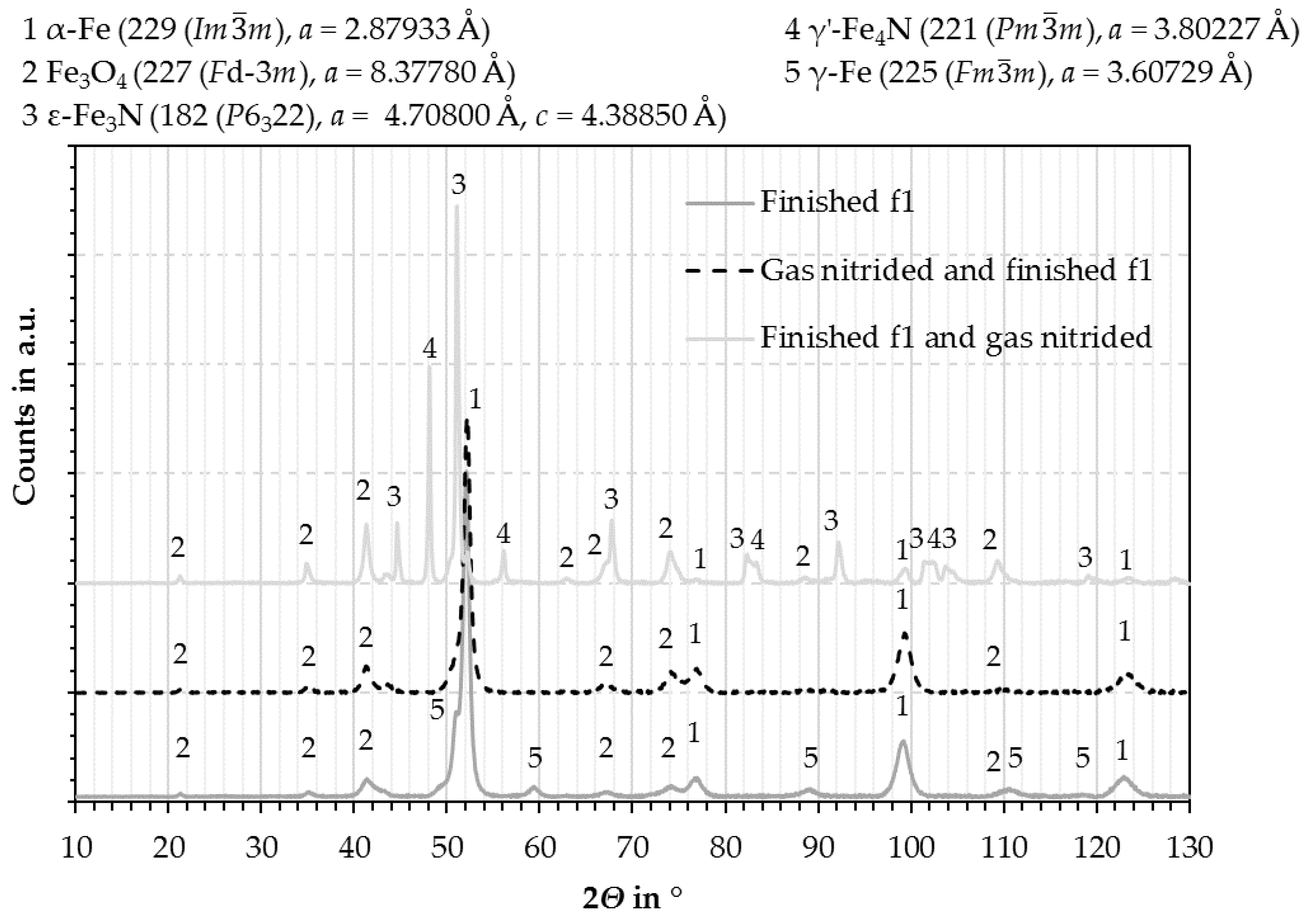
3.1. Coating Characterization

The coating microstructures in the as-sprayed and gas nitrided conditions are shown in Figure 1. The as-sprayed coating presents the typical structure of a wire arc sprayed deposit comprising of steel and oxide lamellas with embedded pores (Figure 1a,b). Small oxide particles might break out during the cross-sectional preparation, causing an overall porosity content of 3.6%.
Figure 1c,d illustrates the gas nitrided coating after etching with Nital. At the surface, a white layer appears with an average thickness of 25 µm ± 9 µm. This coating area indicates the compound layer. Underneath, the diffusion layer, also called the precipitation layer in the case of alloyed steels, formed up to the substrate. The through porosity in the arc sprayed coatings ensures the penetration and coatings enrichment by the gaseous nitriding media in the applied thermochemical treatment process.
XRD analysis demonstrates the phase compositions of the 17Cr steel coatings after finishing in the untreated and gas nitrided state (Figure 2). Before thermochemical treatment (finished f1), the quantitative coating’s phase composition results in a mass fraction of 63% ferrite, 14% retained austenite, and 23% magnetite (Fe3O4) using the Rietveld method. The gas nitriding leads to the formation of hexagonal ε-Fe3N and face-centered cubic γ’-Fe4N phases in the compound layer (finished 1 and gas nitrided). After machining, approximately 150 µm coating material had been removed. According the XRD analysis (gas nitrided and finished f1), the diffusion layer consists of a mass fraction of 73% ferrite and 27% magnetite; FeN or CrN phases are not detected. However, the etched cross-section (Figure 1c,d) suggests that submicron CrN precipitations in the diffusion layer were formed [22].
The comparison of the hardness values confirms the formation of precipitates in the diffusion layer (Table 3). The as-sprayed 17Cr steel layer exhibits an average hardness of 461 HV0.3, which exceeds the coating’s hardness values of 250 to 370 HV0.3 of thermal spray steel coatings produced with less oxidation [17,18,23]. After gas nitriding, the hardness of the diffusion layer averages 556 HV0.3. In Figure 3, the hardness depth profile indicates that the hardness within the layer is independent of the surface distance, not taking into account the compound layer. Additionally, the hardness was determined by nanoindentation (Table 3), which revealed a 25% harder thin compound layer than the diffusion layer. In contrast to that, the magnetite phase possesses a lower hardness than the diffusion layer; however, the precipitation-hardened and oxide areas exhibit similar hardness values on average. As a result, the hardness of the coating showed less heterogeneity in the surface hardened state, not considering the compound layer, compared to the as-sprayed state.

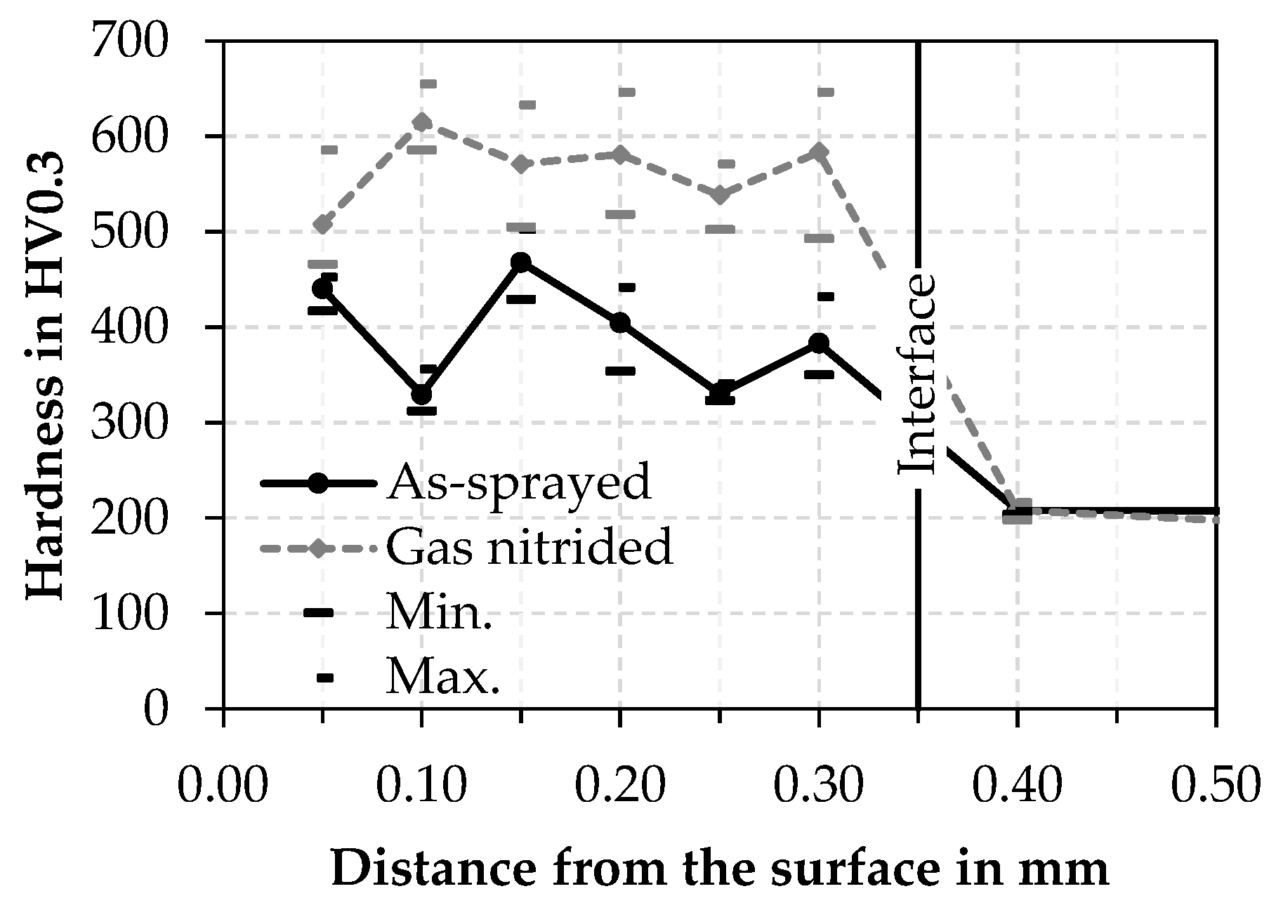
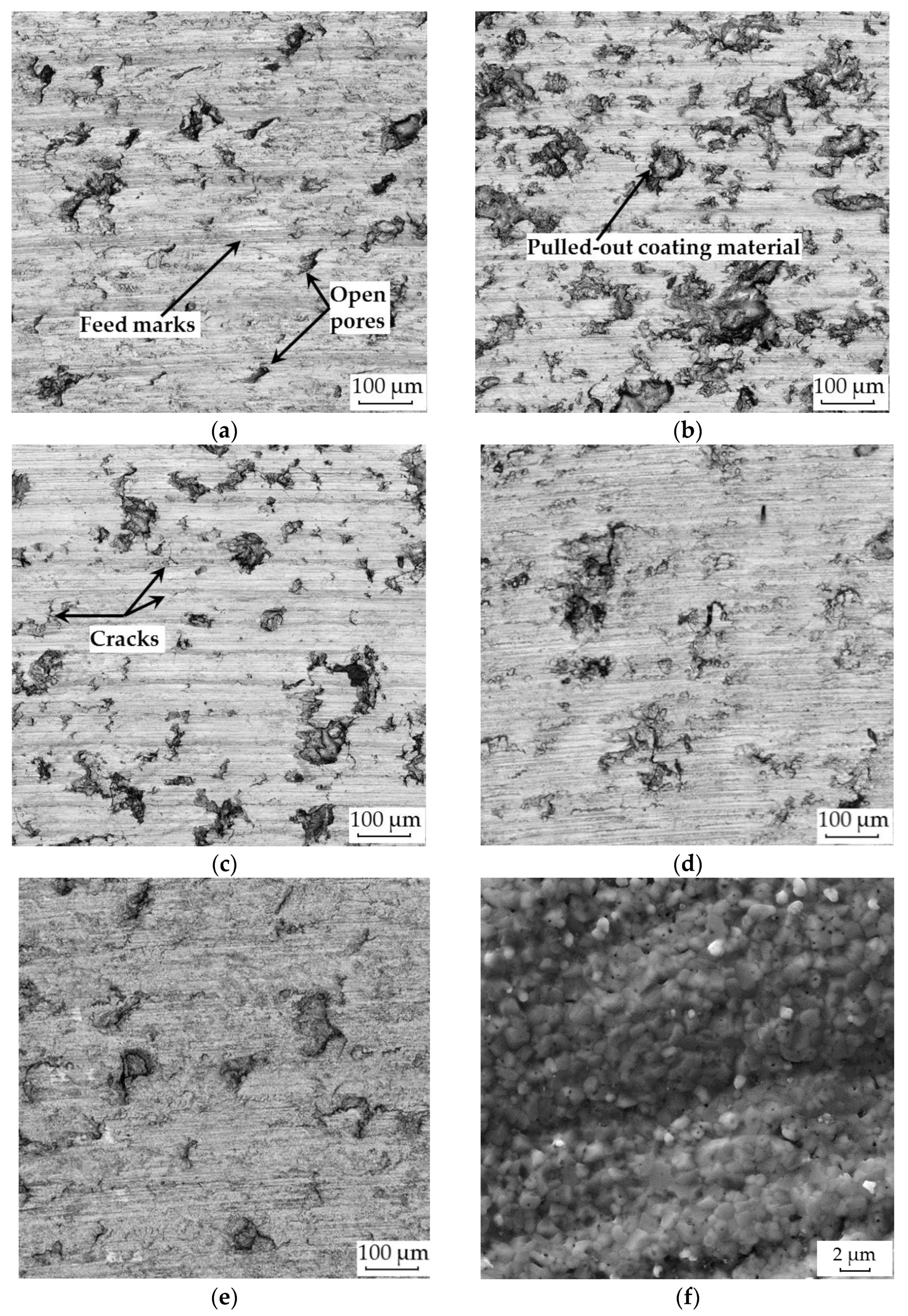
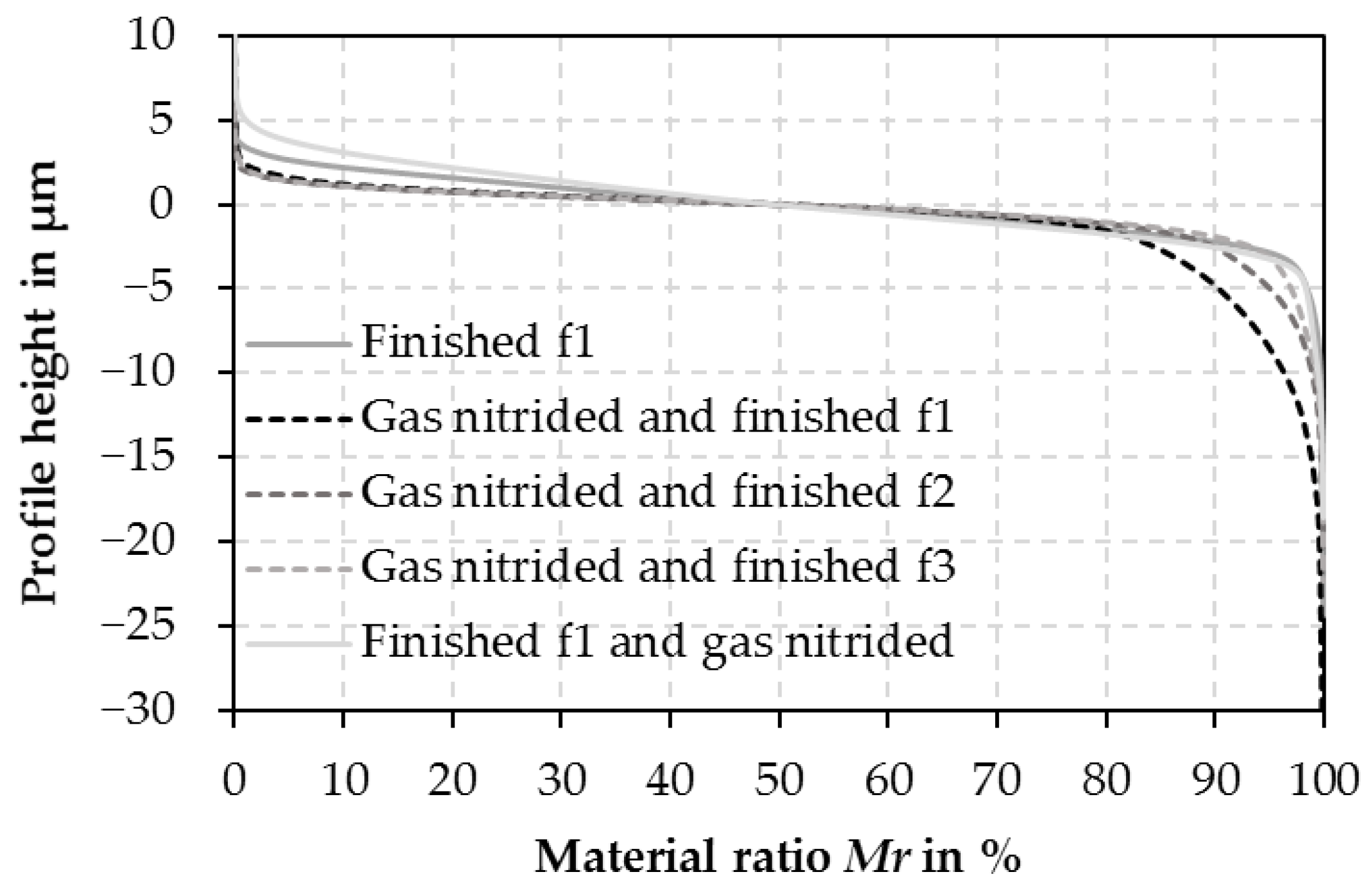
3.2. Comparison of the Surface Properties after Gas Nitriding and Facing

The influence of the surface hardening and the machining process on the surface properties is illustrated in Figure 4 using LSM images of the sample surfaces. The finished surfaces (Figure 4a–d) are characterized by feed marks, opened pores, cracks, and a high valley void volume resulting from coating material pulled-out during the cutting process. The opened pores reflect the coating porosity, but the cracks can also be caused by either the gas nitriding or the finish-machining step.
Using the same machining parameter (f1) before and after nitriding leads to a significant increase in the quantity of pulled-out coating material in the surface hardened condition (Figure 4a,b). The heterogeneous hardness distribution in the just-faced coatings promotes deformation, while the diffusion layer predominantly chips. An increase of the feed or change of the cutting material from CBN to PCD (Figure 4c,d) reduces the volume of pulled-out material. Similar findings were identified in [11]. In contrast to that, the finished and gas nitrided sample (Figure 4e,f) shows the characteristic nubby surface of the hard compound layer. Predominately, the nitrides were formed at the edge of pores and in cracks, and cover the surface nearly completely.
The topography of the different treatment states recorded by laser scanning microscopy is shown in Figure 5 by means of Abbott curves. According to the diagram, a significant increase in the volume fraction of the valleys could be achieved by the process combination of gas nitriding and subsequent face turning. The greatest increase was achieved when using a CBN-tipped indexable insert at a low feed (machining parameter f1), which coincides with the parameter used for facing the as-sprayed coating. Furthermore, the curves show a good correlation with the surface images shown in Figure 4. As a result, an increase of the Rz-value can be related to an increase in pulled-out material areas (Table 4). While, for surface-hardened variants, the profile heights decreased slightly, and generally smaller topographical differences were observed, surface hardening in the finished turned state has no influence on the proportion of removed material. The grown nitrides slightly increased the profile heights. However, the roughness values Ra and Rz are almost comparable to the finished surface in the as-sprayed condition (machining parameter f1, Table 4).
The determined values of the valley void volume Vvv shown in Table 5 confirm the previously described behavior regarding the proportion of pulled-out coating material. The lowest proportions are reached after machining the as-sprayed coating. After nitriding and subsequent machining, the lowest proportion of pulled-out coating particles is achieved when using a PCD-tipped indexable insert and a small feed (machining parameter f3, f = 0.12 mm). This relationship cannot be derived from the standard roughness values Ra and Rz summarized in Table 4, which reveal higher roughness values for the machining parameter f2. When machining nitrided coatings using CBN-tipped tools, higher Vvv-values are reached. Machining the coating with the lower feed increases the proportion of the mentioned surface defects strongly. Similar results regarding the machining with different feeds are also shown in [11]. The higher feed results in higher components of the resultant force while machining due to the increased cross-section of the undeformed chip. Simultaneously, however, the tool-workpiece contact area also increases. Hence, there is a changed distribution of these force components, resulting in less pulled-out coating material. Based on the results, an additional surface hardening process in combination with adjusted machining parameters can significantly influence the surface properties of thermal spray coatings. A superior wear behavior of the coatings due to the surface hardening still has to be proven.

4. Conclusions

The influence of a thermochemical surface hardening process on the final machining behavior of thermal spray steel coatings was investigated. The 17Cr steel coatings deposited by wire arc spraying were successfully gas nitrided, resulting in a compound and precipitation layer. Due to the coating through porosity, a high nitrogen penetration up to the substrate was achieved, which results in a uniform hardness within the precipitation layer compared to the as-sprayed condition. The machining by facing was carried out before and after nitriding. The resulting surface layer was evaluated by tactile and optical surface characterization methods. It was shown that surface hardening led to larger material ratios below the core roughness according to the Abbott curves. Compared to the just-faced condition, the topographical differences were insignificant. In summary, thermochemical treatment of thermal spray steel coatings influenced the cutting behavior. Thus, the possibility of adjusting functional surfaces more specifically is given. Tribological systems with emergency running property requirements could be improved in a targeted manner. However, it has still to be proven whether the surface hardening influences the wear properties of the treated and finished coatings under lubricating conditions.

Author Contributions

Conceptualization, P.K., T.L. (Thomas Lindner), and T.G.; funding acquisition, T.G.; investigation, P.K. and H.L.; project administration, T.G. and T.L. (Thomas Lampke); supervision, T.L. (Thomas Lindner), A.S. and T.L. (Thomas Lampke); validation, P.K. and H.L.; writing—original draft, P.K. and H.L.; writing—review and editing, T.L. (Thomas Lindner) and H.L. All authors have read and agreed to the published version of the manuscript.

Funding

This center has received taxpayer-funded financial support in accordance with the Saxony State Parliament Representatives’ agreed regional budget as part of the High-Performance Center “Smart Production and Materials“. The publication of this article was funded by the Chemnitz University of Technology.
Applsci 11 06520 i001

Institutional Review Board Statement

Not applicable.

Informed Consent Statement

Not applicable.

Data Availability Statement

Nor applicable.

Acknowledgments

The authors thank Marc Pügner for conducting and the support in the XRD and nanoindentation measurements.

Conflicts of Interest

The authors declare no conflict of interest.

References

  1. Edtmayer, J.; Loesch, S.; Hick, H.; Walch, S. Comparative study on the friction behavior of piston/bore interface technologies. Automot. Engine Technol. 2019, 4, 101–109. [Google Scholar] [CrossRef] [Green Version]
  2. Barbezat, G.; Schmid, J. Plasmabeschichtung von Zylinderkurbelgehäusen und ihre Bearbeitung durch Honen. MTZ Mot. Z. 2001, 62, 314–320. [Google Scholar]
  3. Bobzin, K.; Ernst, F.; Zwick, J.; Schlaefer, T.; Cook, D.; Nassenstein, K.; Schwenk, A.; Schreiber, F.; Wenz, T.; Flores, G.; et al. Coating Bores of Light Metal Engine Blocks with a Nanocomposite Material using the Plasma Transferred Wire Arc Thermal Spray Process. J. Ther. Spray Technol. 2008, 17, 344–351. [Google Scholar] [CrossRef]
  4. Ding, K.; Sasahara, H. Study on the machining of iron-based thermal spray coating for sleeveless engine cylinder. Adv. Mat. Res. 2012, 472-475, 991–996. [Google Scholar] [CrossRef]
  5. Ding, K.; Sasahara, H.; Adachi, S.; Nishimura, K. Investigations on the Cutting Process of Plasma Sprayed Iron Base Alloys. Key Eng. Mater. 2012, 447-448, 991–996. [Google Scholar] [CrossRef]
  6. Liborius, H.; Paczkoswki, G.; Nestler, A.; Grund, T.; Mehner, T.; Schubert, A.; Lampke, T. Influence of cutting speed on the surface properties in turning of Fe17Cr2Ni0.2C iron based thermally sprayed coatings. In Proceedings of the International Conference on Competitive Manufacturing, Stellenbosch, South Africa, January 30–1 February 2019; pp. 317–323. [Google Scholar]
  7. Clauß, B.; Liborius, H.; Lindner, T.; Löbel, M.; Schubert, A.; Lampke, T. Influence of the cutting parameters on the surface properties in turning of a thermally sprayed AlCoCrFeNiTi coating. Procedia CIRP 2020, 87, 19–24. [Google Scholar] [CrossRef]
  8. López de Lacalle, L.N.; Gutiérrez, A.; Lamikiz, A.; Fernandes, M.H.; Sánchez, J.A. Turning of thick thermal spray coating. J. Ther. Spray Technol. 2001, 10, 249–254. [Google Scholar] [CrossRef]
  9. Grund, T.; Paczkowski, G.; Lampke, T.; Liborius, H.; Nestler, A.; Schubert, A. Finish turning of FeCr17Ni2C0.2 iron-based sprayed coatings: Influence of substrate preparation, cutting speed and feed on the coating and surface properties. J. Ther. Spray Technol. 2019, 29, 308–318. [Google Scholar] [CrossRef]
  10. Liborius, H.; Nestler, A.; Paczkowski, G.; Schubert, A.; Grund, T.; Lampke, T. Machining of Fe17Cr2Ni0.2C iron based thermally sprayed coatings by turning with special interest to the influence of the depth of cut. In Proceedings of the Special interest Group meeting on Advancing Precision in Additive Manufacturing, Nantes, France, 16–18 September 2019; pp. 100–103. [Google Scholar]
  11. Liborius, H.; Nestler, A.; Paczkowski, G.; Schubert, A. Surface integrity of FeCr17Ni2C0.2 iron based thermally sprayed coatings with special respect to the influence of the feed. MM Sci. J. 2019, 4, 3220–3227. [Google Scholar] [CrossRef]
  12. Wielage, B.; Rupprecht, C.; Lindner, T.; Hunger, R. Surface modification of austenitic thermal spray coatings by low-temperature carburization. In Proceedings of the International Thermal Spray Conference &Exposition, Long Beach, CA, USA, 11–14 May 2015. [Google Scholar]
  13. Adachi, S.; Ueda, N. Formation of S-phase layer on plasma sprayed AISI 316L stainless steel coating by plasma nitriding at low temperature. Thin Solid Film. 2012, 523, 11–14. [Google Scholar] [CrossRef]
  14. Park, G.; Bae, G.; Moon, K.; Lee, C. Effect of plasma nitriding and nitrocarburizing on HVOF-sprayed stainless steel coatings. J. Ther. Spray Technol. 2013, 22, 1366–1373. [Google Scholar] [CrossRef]
  15. Lindner, T.; Mehner, T.; Lampke, T. Surface modification of austenitic thermal-spray coatings by low-temperature nitrocarburizing. In Proceedings of the 18th Chemnitz Seminar on Materials Engineering—18. Werkstofftechnisches Kolloquium, Chemnitz, Germany, 10–11 March 2016. [Google Scholar]
  16. Lindner, T.; Kutschmann, P.; Löbel, M.; Lampke, T. Hardening of HVOF-sprayed austenitic stainless steel coatings by gas nitriding. Coatings 2018, 8, 348. [Google Scholar] [CrossRef] [Green Version]
  17. Adachi, S.; Ueda, N. Wear and Corrosion Properties of cold-sprayed AISI 316L coatings treated by combined plasma carburizing and nitriding at low temperature. Coatings 2018, 8, 456. [Google Scholar] [CrossRef] [Green Version]
  18. Kutschmann, P.; Lindner, T.; Börner, K.; Reese, U.; Lampke, T. Effect of adjusted gas nitriding parameters on microstructure and wear resistance of HVOF-sprayed AISI 316L coatings. Materials 2019, 12, 1760. [Google Scholar] [CrossRef] [PubMed] [Green Version]
  19. Löbel, M.; Lindner, T.; Hunger, R.; Berger, R.; Lampke, T. Precipitation hardening of the HVOF sprayed single-phase high-entropy alloy CrFeCoNi. Coatings 2020, 10, 701. [Google Scholar] [CrossRef]
  20. Lindner, T.; Löbel, M.; Hunger, R.; Berger, R.; Lampke, T. Boriding of HVOF-sprayed Inconel 625 coatings. Surf. Coat. Techn 2020, 404, 126456. [Google Scholar] [CrossRef]
  21. Chao, C.L.; Chen, C.C.; Chang, C.J.; Dong, H.S.; Ma, K.J.; Hsu, W.Y.; Huang, K.C.; Chao, C.W. Single-Point Diamond Turning of Plasma –Nitrided Stainless Steel. KEM 2007, 364–366, 601–606. [Google Scholar] [CrossRef]
  22. Liedtke, D. Wärmebehandlung von Eisenwerkstoffen, 2 Nitrieren und Nitrocarburieren, 7th ed.; Mesenhold, H.J., Ed.; Expert Verlag GmbH: Tübingen, Germany, 2018. [Google Scholar]
  23. Zhao, L.; Lugscheider, E. Influence of the spraying process on the properties of 316L stainless steel coatings. Surf. Coat. Technol. 2002, 162, 6–10. [Google Scholar] [CrossRef]
Figure 1. Light microscopic cross-section images of arc sprayed 17Cr-steel coatings: (a,b) as-sprayed; (c,d) gas nitrided after etching with Nital (EA = embedding agent, C = coating, S = substrate, CL = compound layer, DL = diffusion layer).
Applsci 11 06520 g001
Figure 2. X-ray diffraction diagrams of the arc sprayed 17Cr steel coatings in the finished and gas nitrided state.
Applsci 11 06520 g002
Figure 3. Hardness depth profiles of the arc sprayed 17Cr steel coating in the as-sprayed and gas nitrided state.
Applsci 11 06520 g003
Figure 4. Laser scanning microscope images of the finished surfaces of arc sprayed 17Cr-steel coatings: (a) finished with machining parameter f1; (b) gas nitrided and finished with f1; (c) gas nitrided and finished with f2; (d) gas nitrided and finished with f3; (e,f) finished with f1 and gas nitrided with (f) showing an SEM image recorded with the secondary electrons (SE) detector.
Applsci 11 06520 g004
Figure 5. Abbott curves of the finished surfaces before and after gas nitriding.
Applsci 11 06520 g005
Table 1. Arc spray parameters for 17Cr steel wire.
Spray ParameterValue
Current (A)120
Voltage (V)30
Atomizing gas pressure (bar)4.5
Spraying distance (mm)150
Offset (mm)8
Surface velocity (m/s)0.6
Coating thickness per layer (µm)35
Table 2. Machining parameters for coatings post-treatment.
Machining ParameterCutting MaterialCutting Speed vC (m/min)Feed f (mm)Depth of Cut aP (mm)
f1CBN620.12~0.05
f2CBN0.17
f3PCD0.12
Table 3. The hardness of the arc sprayed 17Cr-steel coatings in the as-sprayed and gas nitrided condition.
HardnessAs-SprayedGas Nitrided
Microhardness (HV0.3)Total coating area461 ± 50556 ± 114 1
Nanoindentation hardness
(GPa)
Compound layer (CL)-10 ± 2.5
Steel lamellas/
Diffusion layer (DL)
6 ± 18 ± 1
Oxide7 ± 1
1 only diffusion layer.
Table 4. Surface roughness of the arc sprayed 17Cr-steel coatings before and after different post-treatments.
Surface StateMachining ParameterRoughness (µm)
RaRz
As-sprayed-14 ± 1.983 ± 11.5
Finishedf11.3 ± 0.17.8 ± 1.1
Gas nitrided and finishedf11.8 ± 0.419 ± 2.7
Gas nitrided and finishedf21.5 ± 0.417 ± 2.4
Gas nitrided and finishedf31.6 ± 0.320 ± 4.2
Finished and gas nitridedf11.4 ± 0.28 ± 1.8
Table 5. Determined valley void volume (Vvv) after machining.
Surface StateMachining ParameterValley Void Volume Vvv (mL/m2)
Finishedf10.296
Gas nitrided and finishedf11.19
Gas nitrided and finishedf20.485
Gas nitrided and finishedf30.334
Finished and gas nitridedf10.279
Publisher’s Note: MDPI stays neutral with regard to jurisdictional claims in published maps and institutional affiliations.

