Abstract
In general, high-speed machines should be designed to satisfy electromagnetic and mechanical characteristics. In this study, the design of high-speed permanent magnet synchronous generator with two different shaft materials considering overhang effect and mechanical characteristics was performed. It was confirmed that the leakage magnetic flux generated by the two shaft materials electromagnetically affects the high-speed generator. Additionally, it is important to accurately predict the natural frequency mode and critical speed to prevent damage and vibration of the rotating body owing to scattering during high-speed rotation. Therefore, the mechanical characteristics of the designed model were analyzed. In this study, we propose a design method that considers both the electromagnetic effects and mechanical characteristics. Subsequently, verification was performed through experiments and comparisons for the validity and reliability of the proposed design method.
1. Introduction
With the advancement of manufacturing technologies, permanent magnet (PM) machines are widely adopted in various industrial fields, such as machines using PMs with high coercive force and residual magnetic flux density. Machines rotating at high speed have the advantage of miniaturization and cost reduction through the application of a direct-drive system connected directly to the shaft of an electric machine without using a gear system [1,2,3,4,5]. Moreover, it has the advantage of high device output and efficiency according to the power conversion device development [6,7]. Owing to these advantages, they are adopted in various fields such as turbine generators, machine tools, and electric vehicle propulsion motors [8,9,10]. However, as the high-speed machine rotates at such a great speed, there exists the issue of damage and loss of the rotor caused by centrifugal force [11,12]. To prevent damage to the rotor, the scattering of PMs is prevented through the sleeve, and with the use of materials having excellent mechanical rigidity for the shaft [13,14]. However, the choice of the shaft material has a significant influence on the electromagnetic and mechanical characteristics of high-speed machines [8].
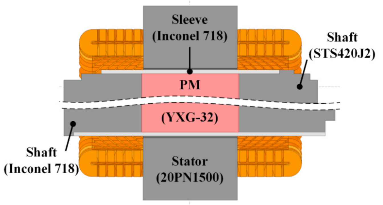
2. Structure of PMSG
In this study, a high-speed permanent magnet synchronous generator (PMSG) with two different shaft materials, that considers the overhang effect and mechanical characteristics, was designed as shown in Figure 1. Since PM operates at high temperature, a samarium cobalt (Sm2Co17) magnet with excellent temperature characteristics was used.
Figure 1.
Shape of high-speed generator according to shaft material.
Furthermore, a sleeve was used to prevent the PM from scattering as it rotated at high-speed, and Inconel 718 material was used for the sleeve [15,16]. Table 1 shows the design requirements of the generator.
Table 1.
Design requirement condition.
3. High-Speed PMSG Characteristics with STS420-J2 Shaft Material
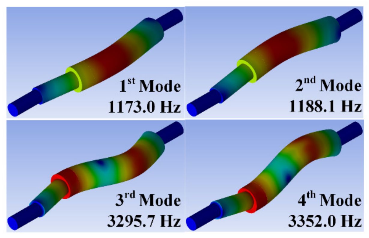
3.1. Mechanical Characteristics
In high-speed rotating machines, there exists the problem of damage and loss of the rotor caused by the centrifugal force. Therefore, it is essential to consider it in the design. Generally, a sleeve is used to prevent PMs from scattering of high-speed rotating machines thus avoiding damage [17]. The thickness of the sleeve was selected considering the electrical characteristics and mechanical stress of the machines. The sleeve thickness of the rotor used in this study was selected as 4 mm, based on the electromagnetic and mechanical conditions. Additionally, it is crucial to accurately predict the natural frequency mode of a rotating body for high-speed machines.
Critical speed causes high-frequency vibration as the vacuum space rapidly increases due to resonance, causing shaft displacement, vibration, and damage to bearings and systems directly [18,19]. Therefore, the critical speed of the rotating body must be accurately predicted, and the equation of motion of the rotating body can be calculated as: [20]
where is the mass, is the gyroscopic, is the stiffness matrix, is the displacement, and is the vector component of the force. The rotating body can be classified into rigid body mode and bending mode according to its shape, and the design should be developed avoiding the bending mode as much as possible. Generally, the resonant frequency at the critical speed is predicted using the Campbell diagram.
With the rotational speed as the horizontal axis and the natural frequency as the vertical axis, the intersection of the rotational speed and the natural frequency can be identified as the resonance area. Figure 2 shows the critical velocity analysis result of the STS420-J2 shaft material through FEM using the value derived from Equation (1). Consequently, the critical speed closest to the rated speed was 41873 rpm. Since modal analysis directly affects the electromagnetic and mechanical vibration of a rotating machine, it is important to check the natural frequency and mode shape. Figure 3 shows the results of modal analysis when rotating at rated speed. At the rated speed of 36,000 rpm, the resonant frequencies are 1173 Hz and 1188.1 Hz in the 1st and 2nd modes respectively, and the resonant frequency intersection occurs at 3295 Hz and 3352 Hz in the 3rd and 4th modes. Frequency means the natural vibration frequency according to each mode, and rigid body mode and bending mode occur at similar frequencies. Therefore, the frequency is derived differently according to the rigid body mode and the bending mode. However, as a result of the analysis, it was confirmed that there was no problem in the design of the rotating body because there was no bending mode intersection at the rated speed.
Figure 2.
Critical speed analysis of STS420-J2 shaft rotor.
Figure 3.
Modal analysis of STS420-J2 shaft rotor.
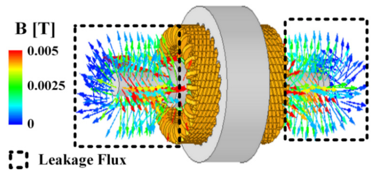
3.2. Influence of Shaft Material on Electromagnetic Characteristics
After ensuring the mechanical stability of the PMSG rotating at high speed, a design that satisfies the rated requirement output of 100 kW and line-to-line voltage of 380 Vrms was developed. Subsequently, to verify the validity and reliability of the designed generator, a high-speed PMSG was manufactured, and an experiment was conducted. Figure 4 and Table 2 shows a comparison of the FEM and experimental results of the manufactured high-speed generator.
Figure 4.
Line to Line voltage and phase current characteristics of STS420-J2 shaft material at load.
Table 2.
Comparison of STS420-J2 Shaft Material FEM and Experiment Results.
As a result of the comparison, there was an error rate of approximately 9.19% in the case of line-to-line voltage and approximately 23.4% in phase current, leading to an end result that does not fulfill the rated output and voltage. Therefore, in this study, the causes of incompatibility with the requirements were analyzed. In general, the voltage drop of a generator is mainly caused by an increase in inductance and a decrease in magnetic flux owing to demagnetization of the magnet. However, it was confirmed that the PM used in the designed generator had no problem even if it was used at the required rated operating temperature because the maximum operating temperature was 300 °C. Therefore, an analysis of the generator inductance characteristics was performed. It was observed from the comparison between the inductance derived through the 3D FEM of the fabrication model and the inductance measured before heat treatment of the rotating body that the error rate was very well matched at approximately 1%. However, as shown in Table 3, by measuring the inductance after heat treatment of the rotating body, it was confirmed that the inductance increased by approximately 22%.
Table 3.
Comparison of FEM and experiment inductance measurements.
This is because the paramagnetic characteristics are transformed into ferromagnetic characteristics during the heat treatment process in the assembly of the rotor. Therefore, as shown in Figure 5, a large leakage magnetic flux occurs at both ends of the shaft, which causes an increase in the synchronous reactance as the inductance increases [21]. The synchronous reactance component is located in the denominator term as follows Equations (2) and (3).
Figure 5.
Leakage magnetic flux of STS420-J2 shaft material.
As the synchronous reactance increases, the voltage drop and current decrease. This voltage drop and current decrease cause an output reduction, as follows:
is the terminal voltage, is the phase current, is the back EMF, is the phase resistance, is the load resistance, and is the synchronous reactance (including self, mutual, and leakage reactance).
4. High-Speed PMSG Characteristics with Inconel 718 Shaft Material
4.1. Electromagnetic Characteristics
Previously, PMSG using the STS420-J2 shaft material was confirmed to have a problem in that the requirements were not satisfied because of the inductance leaking into the shaft as it was transformed into ferromagnetic characteristics during the heat treatment process of the rotating body. Therefore, a design that satisfies the requirements was performed using Inconel 718, which has a non-magnetic characteristic for the shaft material. The magnetic flux leakage through the shaft after the heat treatment of the rotor was confirmed through FEM. This is shown in Figure 6, and it was confirmed that magnetic flux leakage through the shaft hardly occurred.
Figure 6.
Leakage magnetic flux of Inconel 718 shaft material.
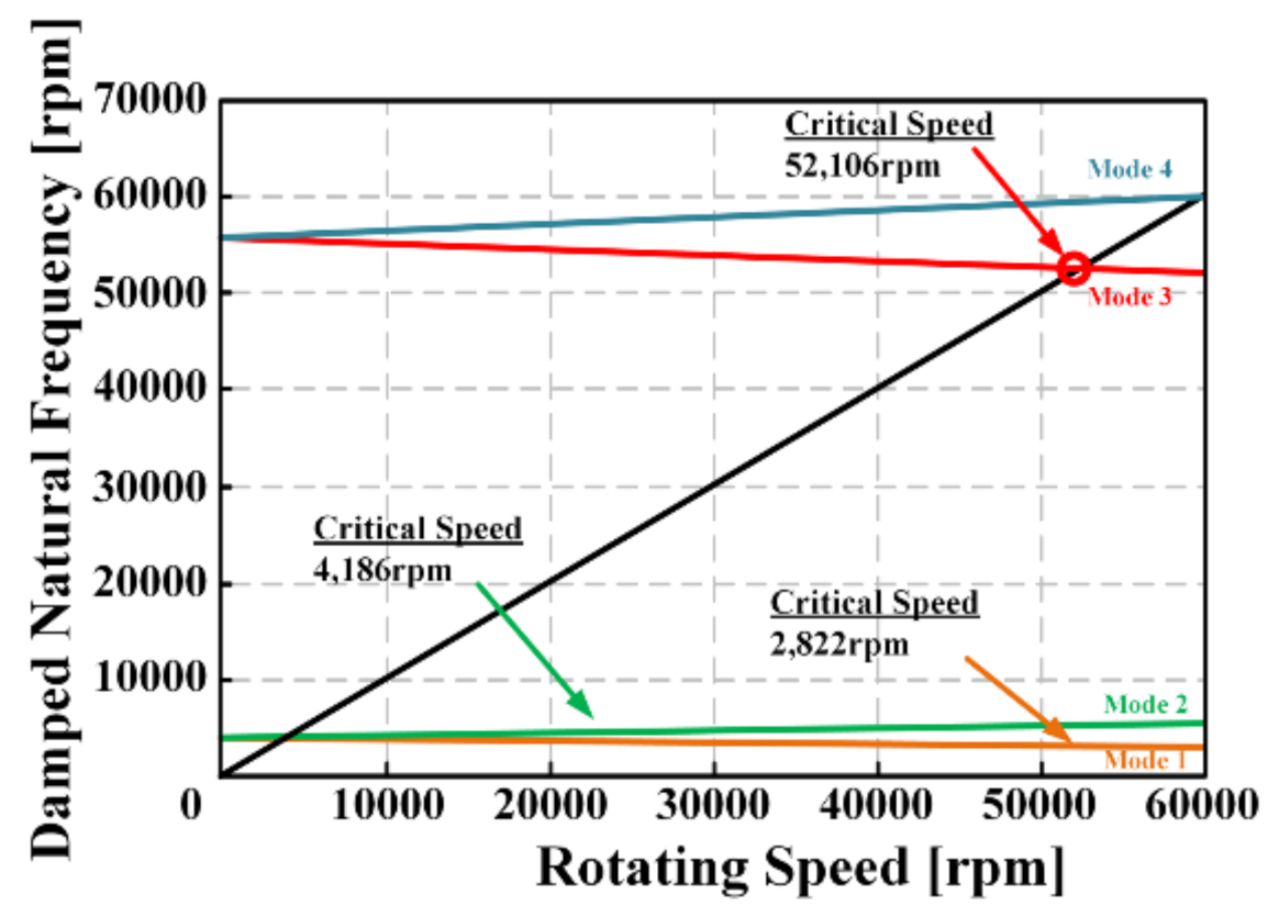
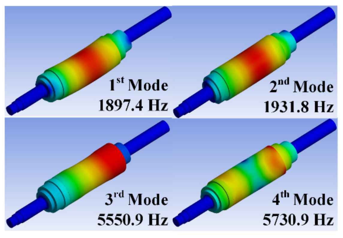
4.2. Mechanical Characteristics
After considering the electromagnetic characteristics of PMSG with Inconel 718 shaft material, mechanical characteristics analysis was performed using the same method as that for PMSG constructed with STS420-J2 material. As a result of the critical speed analysis of Inconel 718, as shown in Figure 7, the critical speed is about 52,106 rpm, which is more stable than the STS420-J2 material because of its favorable mechanical rigidity. In the case of modal analysis, as shown in Figure 8, when operating at the rated speed, the 1st resonant frequency was 1897.4Hz, the 2nd resonant frequency was 1931.8Hz, and the 3rd resonant frequency was 5550.9Hz and 5730.9Hz. Therefore, it was confirmed that there is no problem in the design of the rotating body because the shaft rotating body made of Inconel 718 also has no bending mode intersection at the rated speed.
Figure 7.
Critical speed analysis of Inconel 718 shaft rotor.
Figure 8.
Modal analysis of Inconel 718 shaft rotor.
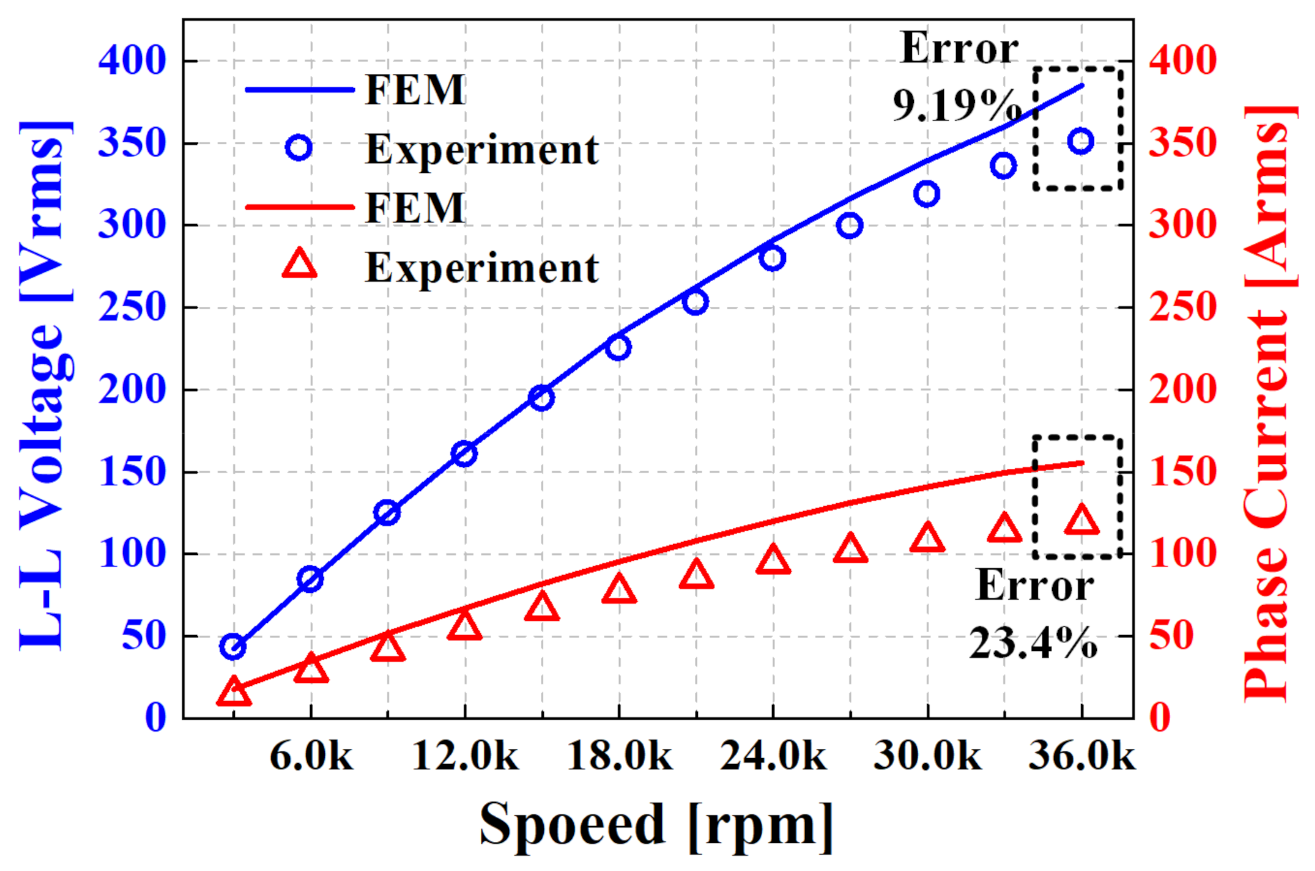
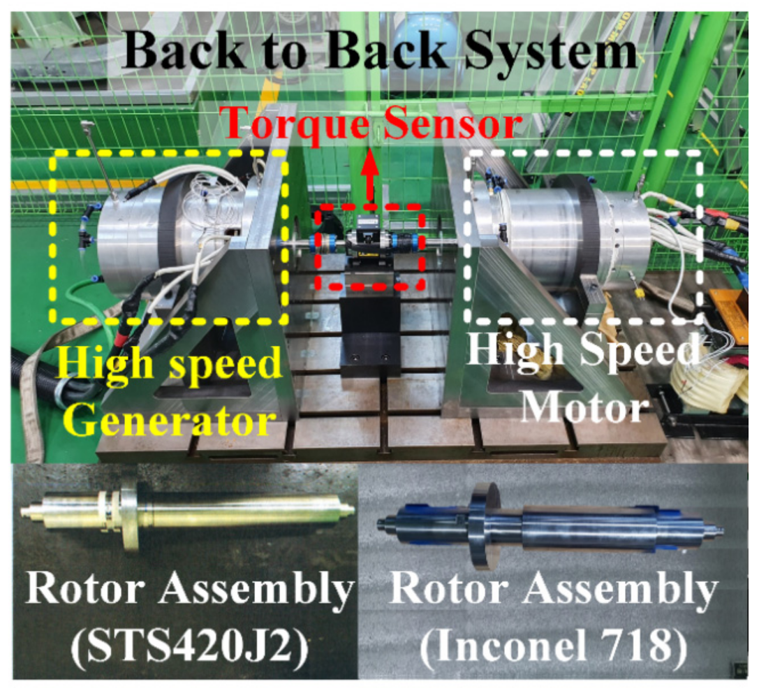
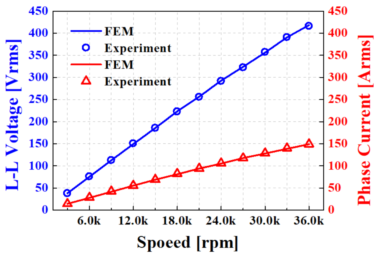
5. Experimental Verification
To verify the validity and reliability of the PMSG presented in the previous section, a system for performance evaluation was constructed, as shown in Figure 9. The performance evaluation method of generator includes a method employing a dynamo or back-to-back system. However, because the generator designed in this study has a large capacity and high rotational speed, it is difficult to establish a performance evaluation using dynamo. Therefore, by constructing a back-to-back system, two rotor types of PMSG experiments were performed. Figure 10 shows the results of the FEM analysis when the Inconel 718 rotor is loaded and the comparison result of the line-to-line voltage and phase current characteristics measured during the experiment.
Figure 9.
Test bed and rotor assembly of high-speed PMSG.
Figure 10.
Line to Line voltage and phase current characteristics of Inconel 718 shaft material at load.
In the case of the Inconel 718 rotor, it has a nonmagnetic characteristic even after heat treatment for coupling the rotor. In addition, since there is no magnetic flux leakage to the shaft, the error rate of the line voltage is about 1.96% and the error rate of the phase current is about 1.89%, so it was possible to obtain a result satisfying very similar electromagnetic characteristics and requirements.
6. Conclusions
In this study, the design was initially executed considering the electromagnetic and mechanical characteristics of the STS420-J2 shaft PMSG, which is less expensive, but has paramagnetic characteristics. However, through heat treatment of the rotor, the paramagnetic characteristics of STS420-J2 were transformed into ferromagnetic characteristics, and the magnetic flux leaked to the shaft, increasing the leakage inductance. This increase in inductance caused a voltage drop and a decrease in the current of the generator while increasing the synchronous reactance, resulting in unsatisfactory performance. Subsequently, the shaft material was changed to Inconel 718, and the design and analysis were performed by applying the same design method. It was confirmed that Inconel 718 has a non-magnetic characteristics, and magnetic flux leakage to the shaft does not occur even when heat treatment of the rotor is performed. The experiment was conducted using a back-to-back system. As shown in Table 4, it was confirmed that the rated output, line-to-line voltage, phase current, phase resistance, and inductance were in agreement with the analysis, and the validity and reliability of the design method were verified.
Table 4.
Comparison of Inconel 718 Shaft Material FEM and Experiment Results.
In this paper, a high-speed PMSG was designed using two different shaft materials considering the overhang effect and mechanical properties. Table 5 shows the material properties and cost of the designed PMSG. For the STS420-J2 material, due to its paramagnetic properties, one more analysis to predict the synchronous reactance after heat treatment is required. STS420-J2 material has lower rigidity than Inconel 718 material. However, considering the cost of about 14 times lower, the overall manufacturing cost can be reduced. In the case of Inconel 718, it has superior rigidity compared to STS420-J2 and has non-magnetic properties, so there is almost no error in analysis and experimentation. However, Inconel 718 is expensive and increases the overall manufacturing cost. As a result, STS420-J2 material is advantageous in terms of cost, while Inconel 718 material has high reliability, which is considered advantageous for PMGS design.
Table 5.
Mechanical characteristics and cost depending on the materials.
Author Contributions
J.-Y.C.; Conceptualization, review and editing, J.-I.L.; original draft preparation, formal analysis and validation, T.-K.B.; writing and formal analysis, H.-K.L.; validation and software, J.-H.W.; review and editing, J.N.; review and editing, All authors have read and agreed to the published version of the manuscript.
Funding
This work was supported by the National Research Foundation of Korea (NRF) grant funded by the Korea government (MSIT) (No. 2020R1A2C1007353) and this research was supported by the Basic Science Research Program through the National Research Foundation of Korea (NRF-2020R1A4A2002021).
Conflicts of Interest
The authors declare no conflict of interest.
References
- Qiu, H.; Tang, B.; Yu, W.; Yuan, S.; Wu, J.; Yang, C.; Cui, G. Analysis of the super high-speed permanent magnet generator under unbalanced load condition. IET Electro. Power Appl. 2017, 11, 1492–1498. [Google Scholar] [CrossRef]
- Zhang, Y.; McLoone, S.; Cao, W.; Qiu, F.; Gerada, C. Power Loss and Thermal Analysis of a MW High-Speed Permanent Magnet Synchronous Machine. IEEE Trans. Energy Convers. 2017, 32, 1468–1478. [Google Scholar] [CrossRef] [Green Version]
- Zhao, L.; Ham, C.; Zheng, L.; Wu, T.; Sundaram, K.; Kapat, J.; Chow, L. A Highly Efficient 200,000 RPM Permanent Magnet Motor System. IEEE Trans. Magn. 2007, 43, 2528–2530. [Google Scholar] [CrossRef]
- Paulides, J.J.H.; Jewell, G.W.; Howe, D. An Evaluation of Alternative Stator Lamination Materials for a High-Speed, 1.5 MW Permanent Magnet Generator. IEEE Trans. Magn. 2004, 40, 2041–2043. [Google Scholar] [CrossRef]
- Ede, J.D.; Zhu, Z.Q.; Howe, D. Rotor Resonances of High-Speed Permanent-Magnet Brushless Machines. IEEE Trans. Ind. Appl. 2002, 38, 1542–1548. [Google Scholar] [CrossRef] [Green Version]
- Hong, D.K.; Joo, D.; Woo, B.C.; Jeong, Y.H.; Koo, D.H. Investigations on a Super High Speed Motor-Generator for Microturbine Applications Using Amorphous Core. IEEE Trans. Magn. 2013, 49, 4072–4075. [Google Scholar] [CrossRef]
- Liu, X.; Liu, G.; Han, B. A Loss Separation Method of a High-Speed Magnetic Levitated PMSM Based on Drag System Experiment Without Torque Meter. IEEE Trans. Ind. Electron. 2019, 66, 2976–2986. [Google Scholar] [CrossRef]
- Shin, K.H.; Bang, T.K.; Cho, H.W.; Choi, J.Y. Design and Analysis of High-Speed Permanent Magnet Synchronous Generator with Rotor Structure Considering Electromechanical Characteristics. IEEE Trans. Appl. Supercond. 2020, 30, 1–5. [Google Scholar] [CrossRef]
- Du, G.; Hang, N.; He, H.; Lei, G.; Zhu, J. Parameter Design for a High-Speed Permanent Magnet Machine under Multiphysics Constraints. IEEE Trans. Energy Convers. 2020, 35, 1–11. [Google Scholar] [CrossRef]
- Gerada, D.; Mebarki, A.; Brown, N.L.; Gerada, C.; Cavagnino, A.; Boglietti, A. High-Speed Electrical Machines: Technologies, Trends, and Developments. IEEE Trans. Ind. Electron. 2014, 61, 2946–2959. [Google Scholar] [CrossRef]
- Zhu, Z.Q.; Howe, D.; Bolte, E.; Ackermann, B. Instantaneous magnetic field distribution in brushless permanent magnet DC motors. I. Open-circuit field. IEEE Trans. Magn. 1993, 29, 124–135. [Google Scholar] [CrossRef]
- Jang, S.M.; Ko, K.J.; Cho, H.W.; Choi, J.Y. Electromechanical parameters calculation of permanent magnet synchronous motor susing the transfer relations theorem. IEEE Trans. Magn. 2007, 43, 2495–2497. [Google Scholar] [CrossRef]
- Jang, G.H.; Ahn, J.H.; Kim, B.O.; Lee, D.H.; Bang, J.S.; Choi, J.Y. Design and Characteristic Analysis of a High-Speed Permanent Magnet Synchronous Motor Considering the Mechanical Structure for High-Speed and High-Head Centrifugal Pumps. IEEE Trans. Magn. 2018, 11, 1–6. [Google Scholar] [CrossRef]
- Ou, J.; Liu, Y.; Breining, P.; Gietzelt, T.; Wunsch, T.; Doppelbaure, M. Experimental Characterization and Feasibility Study on High Mechanical Strength Electrical Steels for High-Speed Motors Application. IEEE Trans. Ind. Appl. 2021, 57, 284–293. [Google Scholar] [CrossRef]
- Ahn, J.H.; Han, C.; Kim, C.W.; Choi, J.Y. Rotor Design of High-Speed Permanent Magnet Synchronous Motors Considering Rotor Magnet and Sleeve Materials. IEEE Trans. Appl. Supercond. 2018, 28, 1–4. [Google Scholar] [CrossRef]
- Zhang, F.; Du, G.; Wang, Y.; Liu, G.; Cao, W. Rotor Retaining Sleeve Design for a 1.12-MW High-Speed PM Machine. IEEE Trans. Ind. Appl. 2015, 51, 3675–3685. [Google Scholar] [CrossRef] [Green Version]
- Zhang, H.; Zhang, X.; Gerada, C.; Galea, M.; Gerada, D.; Li, J. Design Consideration for the Tooth Shoe Shape for High-Speed Permanent Magnet Generators. IEEE Trans. Magn. 2015, 51, 1–4. [Google Scholar] [CrossRef] [Green Version]
- Huang, Z.; Fang, J. Multiphysics Design and Optimization of High-Speed Permanent-Magnet Electrical Machines for Air-Blower Applications. IEEE Trans. Ind. Electron. 2016, 63, 2766–2774. [Google Scholar] [CrossRef]
- Fang, H.; Qu, R.; Li, J.; Zheng, P.; Fan, X. Rotor Design for High-Speed High-Power Permanent Magnet Synchronous Machines. IEEE Trans. Ind. Appl. 2017, 53, 3411–3419. [Google Scholar] [CrossRef]
- Budynas, R.G. Advanced Strength and Applied Stress Analysis; McGraw-Hill Science: New York, NY, USA, 1998. [Google Scholar]
- Shin, K.H.; Jung, K.H.; Cho, H.W.; Choi, J.Y. Analytical Modeling and Experimental Verification for Electromagnetic Analysis of Tubular Linear Synchronous Machines With Axially Magnetized Permanent Magnets and Flux-Passing Iron Poles. IEEE Trans. Magn. 2018, 54, 1–6. [Google Scholar] [CrossRef]
Publisher’s Note: MDPI stays neutral with regard to jurisdictional claims in published maps and institutional affiliations. |
© 2021 by the authors. Licensee MDPI, Basel, Switzerland. This article is an open access article distributed under the terms and conditions of the Creative Commons Attribution (CC BY) license (https://creativecommons.org/licenses/by/4.0/).