1. Introduction
Internet of Things (IoT) networks refers to connecting devices to the Internet [
1]. Connected devices receive instructions from the IoT network and transmit data over the network with minimal human intervention. To enable IoT services, a messaging protocol is required to allow IoT devices to exchange information at remote locations. These application protocols provide device accessibility to IoT networks through the transport layer of the Internet Protocol stack. HTTP (Hypertext Transfer Protocol) [
2] is the most widely used and widely used application protocol.
The processing power of many IoT devices is often limited by limited available resources in terms of computational power and bandwidth. The problem with HTTP is that it requires significant control packet overhead along with the request/response model. On the other hand, the protocols required by IoT services are the support of a small code footprint, low power consumption, low bandwidth consumption, and high latency. For this, we choose MQTT (Message Queuing Telemetry Transport).
MQTT is a lightweight messaging protocol designed for devices with limited computing power in unreliable networks. It uses a topic-based publish/subscribe model and converts messages between devices. Devices of the MQTT protocol are considered clients. The client communicates with a dedicated server called a broker. Whenever a client wants to distribute information, it posts information to the broker under that topic. The broker then sends the posted information to clients that have subscribed to the topic. In other words, clients communicate indirectly about a particular topic through a broker that is responsible for controlling the operations of data transfer between clients.
The MQTT specification recommends the use of Secure Socket Layer (SSL) or Transport Layer Security (TLS) as a complementary protocol for security, but for simplicity, no security protocol is built into the application layer. In addition, due to its lightweight protocol capabilities, many researchers have made it an important priority to provide additional security to MQTT by encrypting application data with low computational overhead. Another option is to improve the data transfer speed and more reliable data transfer in a timely manner, especially for processing multimedia data.
Recently, more home multimedia appliances have joined the IoT network, and many people want to bring the power of IoT network by configuring an IoT server as part of their smart, multimedia, home network. However, since we need to configure a server, there exists an IP address-related technical issue in operating it in home networks. While we agree with the IoT research community in prioritizing of the MQTT protocol, our current work focuses on designing the home network itself and its configuration experiments for IoT service supporting wide range of applications including real-time multimedia applications. With our network configuration, all parts of the home network have access to external networks while access to the IoT server either from the home network or external networks is only granted to the authorized IoT clients. At the same time, other parts of the home network excluding the IoT entities are strategically protected from the internal and external access.
The rest of this paper is organized as follows.
Section 2 briefly introduces the MQTT protocol and its related works. In
Section 3, we state our goals for the network design and its configuration methodology using a packet tracer network emulator while
Section 4 demonstrates the operation of the configured network with the emulator. We conclude the paper and suggest our future work in
Section 5.
2. Related Works
MQTT is a lightweight messaging protocol with extremely small overhead. The lightweight feature comes with a 2-byte only packet header, publish/subscribe model, and bidirectional capabilities to meet the demands of the control systems. The publish/subscribe model allows MQTT clients to publish their information with a particular topic to a MQTT broker as publishers. Each MQTT client can subscribe for a specific topic through the MQTT broker as a subscriber, i.e., MQTT clients are connected to the MQTT broker, which then mediates communications between the MQTT clients. MQTT has a bidirectional communication property, which means any MQTT client can publish or subscribe for any topic handled by the MQTT broker. Therefore, there is no limitation to who or what one can publish or subscribe for across the network, meaning a client can be a publisher as well as a subscriber at the same time.
To implement a smart home network environment, research works were carried out to find a proper messaging and control protocol which can be applied for IoT services. Many candidate protocols including Constrained Application Protocol (CoAP) [
3], Advanced Message Queuing Protocol (AMQP) [
4] and MQTT have been evaluated against HTTP. The performance comparison of HTTP and MQTT when used for IoT systems is discussed in [
5] with the conclusion that MQTT is better than HTTP for IoT network. An experiment to apply MQTT protocol in embedded networks with limited resources was conducted in [
6] with the finding that adopting a MQTT implementation with a single micro-controller board with low hardware specification was even more suitable in embedded networks. The performance overhead of HTTP and MQTT are compared in [
7] using a case study of public bus tracking system. A more comprehensive review of the existing messaging protocols is presented in [
8] where they compared applicability of the protocols across various IoT environments.
An implementation example of home automation system using the MQTT protocol to communicate between the MQTT clients are introduced in [
9] with micro-controller boards with built-in ESP8266 shields. The micro-controllers act as MQTT clients while an online remote server acts as a MQTT broker. A similar paradigm is also introduced in [
10] by developing an IoT-based smart library.
There was some research focused on the enhancement of data quality and reliability using MQTT protocol. An example is performing data acquisition in real time and storing it in the database of a MQTT broker. Additionally, in [
11], mechanisms to develop a MQTT broker equipped with capability to handle multi-protocol architecture was discussed. A research [
12] has been conducted to provide enhancement of security for a MQTT protocol for IoT systems. A depth analysis for IoT security requirements and their countermeasures along with software-defined security was discussed in [
13]. Hardware-level security vulnerabilities of the IoT devices themselves were summarized in [
14] and its test bed are introduced in [
15]. In addition, attempts to apply machine learning [
16] or deep learning [
17] methods to IoT security were introduced.
3. Network Design and Configuration
According to our investigation, unlike the traditional request/response model of HTTP, which tends to impose unnecessary control data even in the many cases of unchanging data, the publish/subscribe model of MQTT can use the available bandwidth more effectively. The compactness and efficiency of MQTT makes it possible to collect, transmit, control, monitor, and analyze significantly larger amounts of data for multimedia applications. However, we need to mention that not all IoT devices are resource constrained, which makes HTTP remain worthy in some IoT networks with its popularity and extendibility. In contrast, if the low battery and bandwidth usage are first priority due to resource constraints of the environment, MQTT is more suitable. Since application developers need to choose between the two protocols depending on the requirements of the target applications, in this paper, we do not discuss the effectiveness comparison of the protocols in IoT network for multimedia applications.
Instead, our aim is designing and configuring an accessible secure home network framework that can be applied in legacy, newly developed, or in-development IoT solutions that prioritize enhanced security and improved performance for multimedia applications. We design the home network to operate IoT devices and their IoT server as shown in
Figure 1.
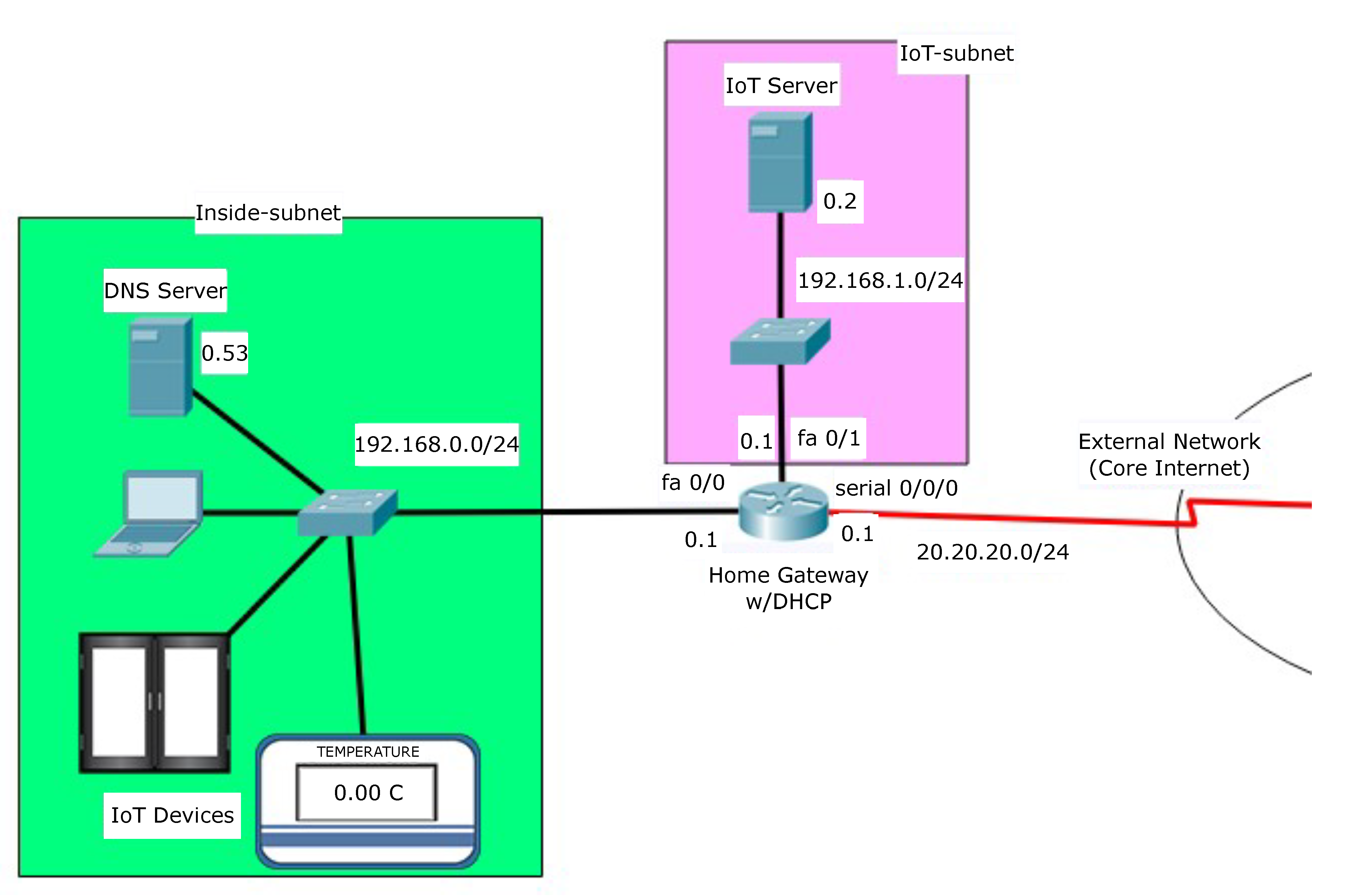
The IoT server can be either a HTTP server or a MQTT broker. We consider the most general case of a home network, where the hosts are interconnected through a routing device such as a home gateway. A typical home gateway has one public IP address (20.20.20.1/24) assigned by its Internet Service Provider (ISP) and comes with a built-in Dynamic Host Configuration Protocol (DHCP) server module, which distributes private IP addresses to its local hosts within the range of its IP address pool (192.168.0.0/16). In our design, we divide the home network into two subnets—the inside-subnet and the IoT-subnet. We locate the IoT devices in the inside-subnet and the IoT server in IoT-subnet.
This structural design separates the IoT server from other parts of home network, which in turn allows the IoT server to operate as an independent host providing IoT services to the external network. Since there are two subnets, the home gateway performs a subnet masking with a given 192.168.0.0/16 address pool, 192.168.0.0/24 for the inside-subnet, and 192.168.1.0/24 for the IoT-subnet. Therefore, the home gateway is configured with three IP addresses with three interfaces. As shown in
Figure 2, the home gateway has 192.168.0.1 to connect the inside-subnet, 192.168.1.1 to connect IoT-subnet, and 20.20.20.1 to connect to the external network. The Network Address Translation (NAT) and access-group configuration will be discussed later in this paper.
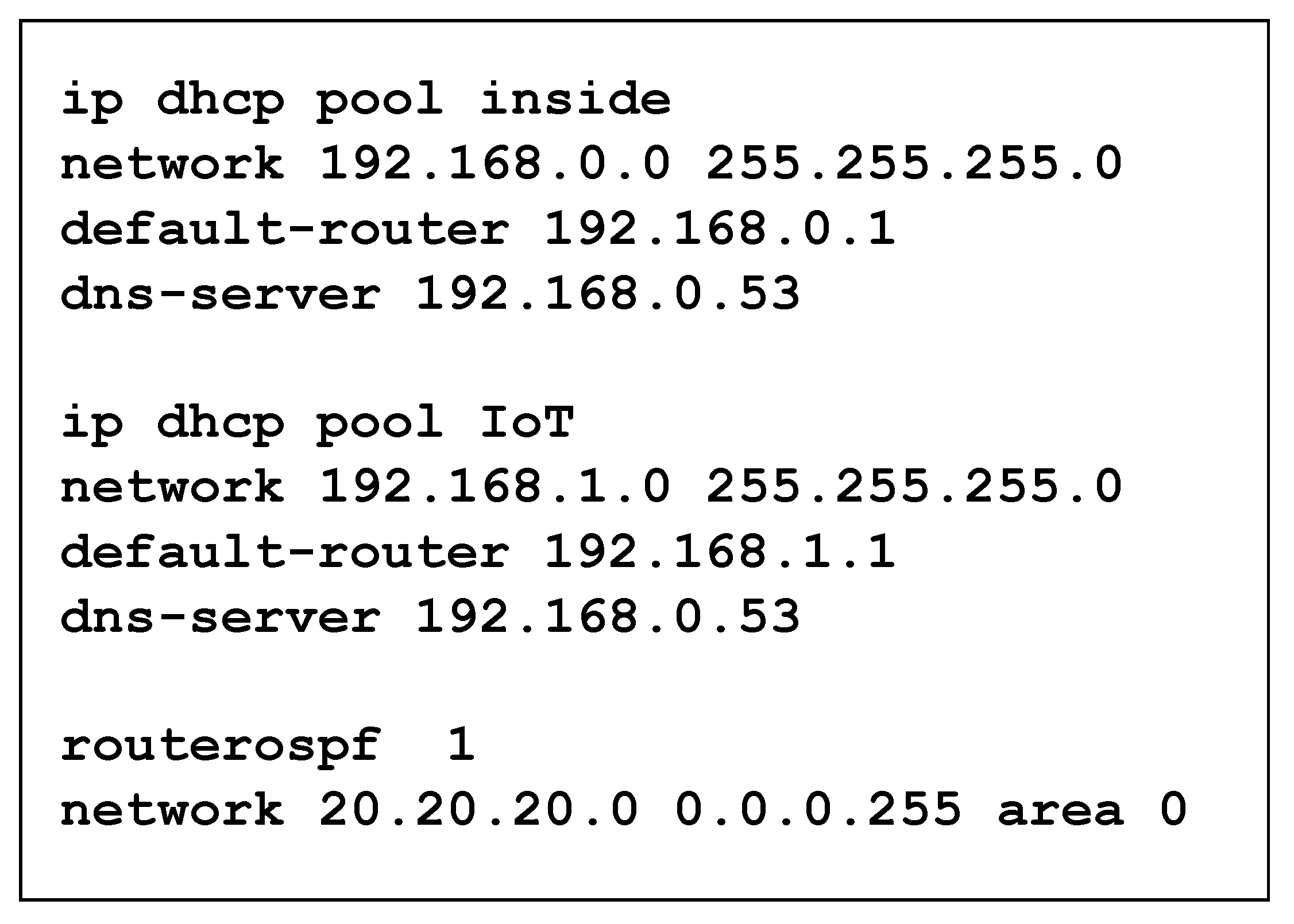
In the inside-subnet, the Domain Name System (DNS) server has a static IP address 192.168.0.53 and dynamic IP addresses are assigned by the home gateway. In the IoT-subnet, we set a static IP address 192.168.1.2 for the IoT server. If we add additional hosts to the IoT-subnet, their dynamic IP addresses will be assigned by the home gateway. To implement these IP address configurations for the home network, we define the DHCP pool named inside and IoT, respectively and give associated commands on the home gateway. Finally, a routing protocol is applied to the home gateway to connect the external network. Even though a proper selection of routing protocol is beyond the range of this paper, among the five available routing protocols in packet tracer emulator including static routing, Boarder Gateway Protocol (BGP), Routing Information Protocol (RIP), Enhanced Interior Gateway Routing Protocol (EIGRP), and Open Shortest Path First (OSPF), we adopt the OSPF protocol for the purpose of possible extension to a large-scale network. The configuration commands for DHCP and routing protocol are shown in
Figure 3.
With the given network design, we outline our configuration goals as follows.
- (1)
Allows all hosts on the home network outbound access to connect to the Internet.
- (2)
Allows authorized hosts on the Internet inbound access to IoT server.
- (3)
Does not allow any hosts on the Internet inbound access to other hosts in the home network.
- (4)
Does not allow the IoT server inbound access to other hosts in the inside-subnet except for essential hosts such as the IoT devices or the DNS server.
Since each host in the home network has a non-routable private IP address, we first need to carry out a Network Address Translation (NAT) with a Port Address Translation (PAT) and Access Control List (ACL) configuration on the home gateway. The NAT rule translates the non-routable private IP address to a public IP address, which is routable on the Internet. In our case, the home gateway translates the private IP addresses of the hosts in the inside-subnet to the home gateway’s outside interface IP address Serial0/0/0. Owing to the NAT rule, all hosts in the inside-subnet can initiate their communications to the external network with a shared routable public IP address. To handle the returning packets from the external network, the PAT rule is applied with “overload” for the home gateway to decide a specific destination hosts on the inside-subnet.
If the same NAT/PAT rule is applied to the IoT-subnet, the IoT server on the IoT-subnet can access the Internet. However, the communication cannot be initiated from the external network because the NAT/PAT itself does not have a bidirectional property. It means the authorized IoT clients located in external network cannot access to the IoT server because they have no way to initiate a communication to the IoT server. Therefore, we need to explicitly configure the NAT/PAT rule so that IoT clients on the Internet can reach the IoT server by accessing 20.20.20.1 on TCP port 80 in the case of the HTTP server and port 1883 in the case of the MQTT broker. This is possible because the initiation request destined to the public IP address 20.20.20.1:80 is statically translated to the private IP address 192.168.1.2:80. Using the configuration in
Figure 4, our goal (1) is achieved.
Now, we set an extended ACL policy, named “access-list 100”, to be applied to the external interface Serial0/0/0 of the home gateway to control access from external network considering our goal (2) and (3). At first, we need to explicitly permit traffic from the external network to the IoT-subnet provided the traffic is destined to the HTTP server. However, other traffic destined to the inside-subnet is denied access by the home gateway. Even though traffic from the external network is permitted by default without access-list creation, we need to note that once the access-list on the gateway is created, it implicitly denies any traffic except for the previously permitted traffic on the same access-list. Therefore, to allow the returning packets as a response of the initiated packets from the hosts on the inside-subnet to pass through the home gateway, we explicitly permit other traffic. This ACL configuration policy is shown in
Figure 5. Additionally, when this policy is applied to the external interface of the home gateway as shown in
Figure 2, our goals (2) and (3) are achieved while still satisfying goal (1) by controlling the inbound traffic at the home gateway.
For our goal (4), we need to define traffic control between the inside-subnet and the IoT-subnet. In our configuration, we located the DNS server (192.168.0.53) and the IoT devices on the inside-subnet, which are essential hosts to the IoT server for external Internet access with domain name and providing IoT service to the external network. The home gateway now allows only that specific traffic destined to the inside-subnet from the IoT-subnet and blocks other traffic following the corresponding commands as shown in
Figure 6. All other traffic from the IoT-subnet is still able to access to the external network through the last policy in access-list 101. The access-list is applied to the inbound interface of IoT-subnet shown as in
Figure 2.
4. Demonstration
To demonstrate the operation of the proposed design and configuration, we further extend the given network to include the external network with IoT clients and an external web server. The overall design is depicted in
Figure 7. Two authorized IoT clients (laptop PC, and a smartphone device), one unauthorized host, and one external web server are located on external network. All hosts on the external network have IP addresses assigned with static or dynamic allocation method depending on the availability of DHCP service on their given network. The routers on the core Internet are running the OSPF routing protocol and interconnected through a serial connection.
At first, we show that the NAT/PAT, and ACL configuration defined in the previous section works as we intended and meeting our goals. To show how the hosts on the inside-subnet network connect to the external network, we let the home PC on the inside-subnet send dummy packets to the external web server (120.120.120.20) with a ping command. Then the home PC will access the web server by sending a HTTP request then check if it gets a HTTP response from the web server. The front page of the web server is displayed on its browser. As shown in
Figure 8, this process is successfully done.
For the first ping packet to the web server 120.120.120.20, a timeout occurs because the Address Resolution Protocol (ARP) table was not constructed on the underlying router of the web server at the initial phase. Once the ARP table is created, all the ping packets will then successfully echo back to the home PC. A similar process is performed from the IoT server to the external web server to check accessibility to the external network from the IoT-subnet. In our ACL configuration on the IoT-subnet interface, we allow the IoT server can access to the DNS server on the inside-subnet. To check the accessibility to the DNS server, the IoT server now connects to the external web server with the domain name (
www.jinsukbaek.com (accessed on 27 May 2021), notes: this website exists only in simulation. ) instead of IP address (120.120.120.20). As we can see in
Figure 9, the network connection works as we intended.
We also require the connection to be initiated from the external network to the IoT-subnet, i.e., IoT client (120.120.120.10) on the external network successfully connects to IoT server. Since we configure NAT/PAT on the home gateway, the inbound packets to the IoT server should be destined to the translated public IP address 20.20.20.1 instead of its original private IP address 192.168.1.2.
Figure 10 shows the screenshot of the corresponding process. Of course, hosts in the external network cannot access any hosts on the inside-subnet due to our ACL configuration on the home gateway.
We now consider the case when the IoT server acts as a HTTP server for IoT service. As a simple demonstration scenario, we consider the autonomous window open system depending on the current temperature. To implement this, we require the IoT device, in this case the thermostat, to send its sensed temperature information to the IoT server. The IoT server continuously monitors the temperature data received. When the temperature value is equal or greater than 25 °C, the server sends the “open window” command to another IoT device, in this case, window which will open the window. The corresponding setup is shown in
Figure 11.
The authorized IoT client can access the IoT server and monitor the status of the IoT devices as shown in
Figure 12. We can see the window is closed since the current temperature is 0 °C. If we artificially increase the temperature up to 25 °C, we could see the window opens.
Since the IoT server acts as a HTTP server, we could check the HTTP, TCP, and IoTTCP protocols involved in the communications among the IoT entities when we capture the traffic flow on this process as shown in
Figure 13. However, it cannot directly access and control the IoT devices because they are in the inside-subnet and access to those devices is not allowed by the ACL configuration of the home gateway.
Finally, we show a similar demonstration scenario in works when the IoT server acts as a MQTT broker for IoT service. In this experiment, the home PC acts as a MQTT publisher by checking the temperature from the IoT device while the IoT clients act as MQTT subscribers to monitor the status of the IoT devices. For this demonstration we assume the MQTT publisher sends current temperature information with the topic “temperature” while the MQTT subscriber receives the same topic information, “temperature”. This communication is mediated by the MQTT broker.
Figure 14 shows the MQTT subscriber receiving the temperature information, 12.75 °C and 11.09 °C from the MQTT broker. The packet capture for this process is shown in
Figure 15, whereas we can see the subscribed information arrives at the authorized IoT client as a MQTT packet.
4.1. Performance Evaluation
In our simulation, our interest was to observe how long additional processing delay is introduced at the home gateway when our proposed access controls are activated. We simultaneously run two concurrent emulators to evaluate the end-to-end delay for two different cases.
All simulations are performed in the same network environment in terms of packet size, network bandwidth, transmission distance, hop counts, and the level of background traffic. This environment does not allow various delays such as transmission delay, propagation delay and queuing delay to affect the difference in end-to-end delays between the two cases. Therefore, if there is an observed difference, it can be considered to be an additional processing delay. We run a web browser at the IoT server to access the web server,
www.jinsukbaek.com (accessed on 27 May 2021), notes: this website exists only in simulation, located in an external network. Our experiment was conducted over 15 different time frames. In each time frame, the IoT server attempts to connect to the web server 5 times, and we observe the maximum and average end-to-end delay of the five accesses to get a front web page of the web server. Since we could not find any difference on minimum end-to-end delay, the observed maximum and average end-to-end delay over time frames are shown in
Figure 16 and
Figure 17, respectively.
Although both the maximum and the average end-to-end delays between the two cases are showing a similar pattern, we can see that the average end-to-end delay shows a more consistent and stable performance over time frames. In both the maximum and the average end-to-end delays, we can see that case 1 introduces more end-to-end delay than case 2 in most time frames. This is because the IoT server must pass through the access-list 102 check list to contact the DNS server to get an IP address of the web server and its outbound HTTP request message should be checked against the access-list 102 if it is destined to the inside-subnet. However, case 1 does not always impose the extra delay in all time frames because the IP address of the web server can be cached in its local web browser while the destination IP address can also be saved in the home gateway’s routing table.
We also evaluated the end-to-end delay from a smart phone in an external network to IoT server for two cases. In the case 2, we only deactivated one rule from access-list 100 checking if HTTP or MQTT requests are destined to the inside-subnet. The NAT/PAT rule translating the gateway interface 20.20.20.1 to the corresponding IoT server address 192.168.1.2 with port overload is still applied since it is required for a normal network operation rather than security control. We could not find any meaningful difference between the minimum, maximum, and average end-to-end delay between the two cases. As we can see in
Figure 18, one case does not outperform the other over time frames. The effect of the excluding one rule from access-list 100 is negligible. Furthermore, its performance depends on the underlying 4G cellular tower.
The introduced average additional processing delays over 15-time frames are 6.13 ms in
Figure 16, 2.4 ms in
Figure 17, and 0.6 ms in
Figure 18, respectively. When we consider today’s state of the art routers’ processing capability, our proposed secure configuration will not impose any significant performance degradation of network to achieve enhanced security.
4.2. Discussions
The home gateway is the most important network entity in a home network. It is responsible for monitoring all safety aspects in both inbound and outbound traffic of the network. It controls all the Wi-Fi enabled home devices such as smart phones, tablets, laptops, etc. in accessing the Wi-Fi network. If some unauthorized user gains access through the home gateway, the home network and the associated home devices can be easily compromised. It is, therefore, essential to keep the home gateway as secure as possible without losing its intended functionality.
Unfortunately, not all home network users assume adequate security posture in this respect. They just rely on the bare minimum home network security provided by the Wi-Fi Access 2 (WPA2) security with the requirement of a password to restrict access to the home gateway. Currently, many home gateways are equipped with low-level software called firmware which controls their operations. However, the firmware sets the security by defining only the standard rules for home networks. In addition, users must manually keep the firmware up to date by installing security patches, a process that varies depending on the given home gateway. Another feature designed to make easy remote access from external networks to the home gateway is the Universal Plug and Play (UPnP), which operates with a turn on/off mode. However, if it is set to the off position, the user cannot access the home gateway even with admin-level access. Moreover, the UPnP can also be used by a malware program to compromise security settings of the home gateway.
Even though many home gateways are now equipped with the above-mentioned security features and reflects the importance placed on security and reliability in home networks, there are still many important security settings that require end user intervention and customization for their target home networks to achieve adequate security. We define four goals for such customization and configuration and demonstrate the goals achieved with the proposed secure configuration. Since IoT services in a home network involve HTTP as well as MQTT with no built-in security features, our proposed configuration supports both the HTTP server and the MQTT broker. We also claim that one of the highest risks to a home network is that the network itself can be compromised by trusted network entities within the home network. For example, once an attacker gains access to a smart phone or laptop, the home network can be easily compromised through the opened entry point of the trusted network entity. To cope with this, we logically isolate the IoT-subnet from other networks and control access at the home gateway with NAT/PAT and ACL configuration.
For the home network performance in terms of Quality of Service (QoS), network latency among the network entities within a home network can be a critical metric. The proposed secure configuration will not bother to provide seamless IoT services with latency issue because (1) most of the IoT devices are equipped with a micro-controller with a built-in high-speed Wi-Fi enabled module ESP8266, and (2) various delays such as transmission delay, propagation delay, processing delay, and queuing delay contributing to user-experienced latency are not significant when we consider home network environments including improved bandwidth, physical transmission distance, processing speed and experienced level of congestion of the home gateway.


