Article

A Perforated Plate with Stepwise Apertures for Low Frequency Sound Absorption

School of Mechanical & Automobile Engineering, Qingdao University of Technology, No. 777 Jialingjiang Road, Qingdao 266520, China
*
Author to whom correspondence should be addressed.
Appl. Sci. 2021, 11(13), 6180; https://doi.org/10.3390/app11136180
Submission received: 9 May 2021 / Revised: 28 June 2021 / Accepted: 29 June 2021 / Published: 2 July 2021
(This article belongs to the Special Issue Acoustic Properties of Absorbing Materials)

Abstract

:
A perforated plate with stepwise apertures (PPSA) is proposed to improve sound absorption for low frequencies. In contrast with an ordinary perforated plate with insufficient acoustic resistance and small acoustic mass, the perforated plate with stepped holes could match the acoustic resistance of air characteristic impedance and also moderately increase acoustic mass especially at low frequencies. Prototypes made by 3D printing technology are tested in an impedance tube. The measured results agree well with that of prediction through theoretical and numerical models. In addition, an absorber array of perforated plates with stepwise apertures is presented to extend the sound absorption bandwidth due to the introduced multiple local resonances.

1. Introduction

Porous materials and resonant structures are widely used for sound absorption [1,2]. Typical resonant structures for sound absorption are perforated plates, micro-perforated plates, Helmholtz resonators and thin plate resonators. One of the conditions for effective sound absorption in resonant structures is that their acoustic resistance should match the characteristic impedance of the air. Usually, the acoustic resistances of an ordinary perforated plate with apertures in the range of a few millimeters to centimeters are insufficient and therefore the absorption coefficients are very small. In building acoustics, perforated plates with large perforation ratio are often used as protective plates over porous layers for sound absorption [3,4,5]. To replace porous materials, Maa proposed a well-known micro-perforated plate (MPP) for sound absorption in the 1970s [6]. For MPP, the apertures are reduced to submillimeter and thus sufficient acoustic resistances can be provided when the perforation ratio is specified. Additionally, in contrast with Helmholtz resonators, when the frequency is away from the resonance frequency, the acoustical reactance of MPP increases slowly to ensure the value is smaller than that of the acoustical resistance in a wide bandwidth, and this characteristic guarantees the broadband absorption of MPP.
When the perforation ratio is constant, MPP with smaller aperture has better sound absorption performance, while in the meantime, the number of holes is increased and the thickness shall be thinner [7]. The increase of hole numbers will increase the cost for the perforation and thinner plates may result in insufficient strength in application. In contrast, a thick MPP with small apertures will lead to excessive acoustic resistance and a decrease in sound absorption performance. To reduce the acoustic resistance of a thick MPP, MPP with variable section have been proposed in recent years [8,9,10,11]. Randeberg [8] proposed a micro-horn shaped MPP and the numerical results showed that micro-horn perforation has the potential to improve the sound absorption bandwidth. Sakagami et al. [9] conducted a pilot study to improve the absorption of a 10 mm thick MPP using a tapered perforation, and the measured results exhibited the shift of the resonant frequency to lower frequencies, but the absorption peak decreases. Lu et al. [10] studied the acoustic properties of MPP with variable cross-section, and showed that the absorption performance of such MPP mainly depends on the part of small holes, and the part of large holes is only to increase the plate thickness. He et al. [11] experimentally analyzed the effects of tapered and stepped holes on the sound absorption performance of thick MPP, and the results showed that large tapered holes can broaden the absorption bandwidth in the higher frequency domain. Based on the MPP model, Ma [12] performed an equivalent simulation of the experimental results for a tapered MPP, and the equivalent aperture obtained is between the large part and the small part of the tapered hole. Qian et al. [13] developed a numerical model of MPP with a tapered hole in the acoustic module of COMSOL Multiphysics, and the simulation results showed that the absorption performance of MPP with tapered holes was mainly influenced by the inlet diameter and outlet diameter. In addition, Jiang et al. [14] gave an empirical impedance correction model related to the cross-sectional ratio based on 176 sets of numerical simulations. These aforementioned literatures concern with reducing the excess acoustic resistance of large-thick MPPs by replacing straight-through holes with sub-millimeter variable cross-section holes.
In comparison with MPP, perforated plates with large apertures have the advantage of less perforation holes if the acoustic resistance can be improved sufficiently through some ways. Recently, various perforated structures for low to medium sound absorption, such as perforated panel with extended tubes (PPET) [15], composite honeycomb sandwich panels (CHSPs) [16], perforated composite Helmholtz-resonator (PCHR) [17], coiled space resonators (CSRs) [18], parallel-arranged perforated panel absorbers (PPAs) [19], panel containing coiled Helmholtz resonators [20] and inhomogeneous multi-layer Helmholtz resonators with extended necks (HRENs) [21], have been investigated. However, perforated plates with stepwise apertures for low frequency sound absorption have not been reported. For this motivation, a perforated plate with stepwise apertures (PPSA) larger than 1.5 mm is proposed for low-frequency (100–300 Hz) sound absorption in a compact space.
Additionally, the array structures consisting of multiple sub-absorbers in parallel arrangement have been studied to improve the sound absorption. Cha et al. [22] designed a MPP absorber array with two different cavities and gave the measured normal absorption coefficients by impedance tube. Wang et al. [23] established a numerical model to study the sound absorption mechanism of a MPP absorbers array with different cavity depths in detail. Uenishi et al. [24,25] studied a permeable membranes absorber array (PMAR) numerically and experimentally, and the results showed that PMAR is an effective absorbing structure due to the influence of multiple locally reacting air cavities at different depths. Furthermore, Wu et al. [26] proposed a profiled structure using perforated plates in some wells, thus adjusting the depths of the wells to improve low frequency absorption. In this paper, based on the local resonance effect, without changing the structure parameters, a simple PPSA absorbers array is initially designed to extend the sound absorption bandwidth only by inserting one rigid partition plate in the air cavity.
This paper is organized as follows. In Section 2, theoretical and numerical models are developed to predict the absorption coefficients of PPSA sound absorbers, and the predictions are verified by impedance tube measurements. In Section 3, the sound absorption performances of PPSA absorber and single perforated panel (PP) absorber are compared and discussed, and a simple array structure of two PPSA absorbers in parallel is presented to improve low frequency sound absorption. Finally, conclusions are drawn in Section 4.

2. Models and Methods

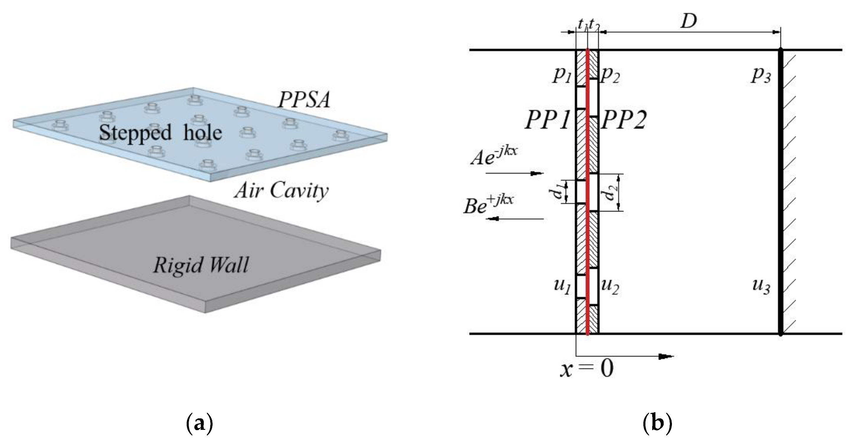
2.1. Theoretical Calculation
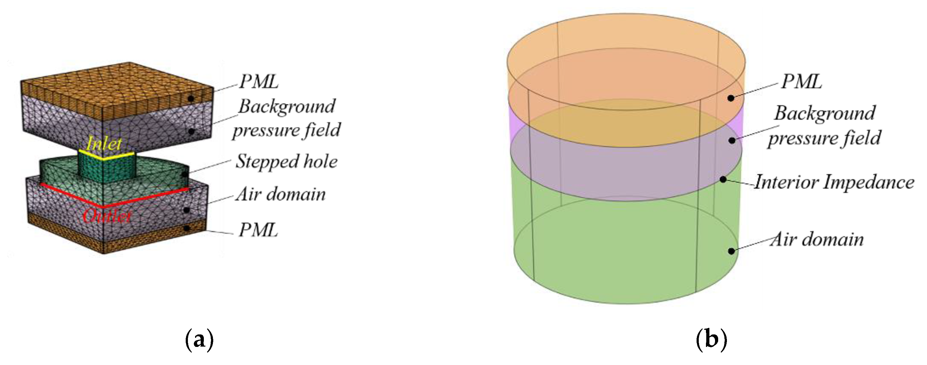
Figure 1a shows the structure of a PPSA absorber, which consists of a PPSA and an air cavity supported by a rigid wall. The PPSA is perforated with a series of stepped holes, which are composed of two unequal circular apertures in the coaxial line. For each circular aperture, the ratio of diameter to depth is greater than 1 and the diameter is not less than 1.5 mm. The diameter, thickness and perforation ratio of the small aperture are d1, t1, σ1, those of the large aperture are d2, t2, σ2, respectively, and the air cavity depth is D. Structurally, PPSA can be viewed as a serial combination of two perforated panels PP1 and PP2 without spacing.
Based on the transfer matrix method [27], for the one-dimensional acoustical system element of PPSA absorber, as shown in Figure 1b, the sound pressure p1 and particle velocity u1 on the left side and the sound pressure p3 and particle velocity u3 on the right side can be expressed as:
[ p 1 u 1 ] = [ T 11 T 12 T 21 T 22 ] [ p 3 u 3 ] ,
where T11, T12, T21 and T22 are the four pole parameters of the total transfer matrix [T]. The total transfer matrix [T] is obtained by multiplying the unit transfer matrix of PP1, PP2 and air cavity, written as:
[ T ] = [ T PP 1 ] [ T PP 2 ] [ T A i r ] ,
For PP1 and PP2, the transfer matrix [Tpp] can be given as:
[ T PP 1 , 2 ] = [ 1 Z P 1 , 2 0 1 ] ,
The acoustic energy loss of the perforated panel mainly includes the air viscous dissipation inside the hole and the end correction caused by viscous friction and sound radiation. Therefore, the acoustic impedance of perforated panel is the sum of the acoustic impedance inside the hole and the end correction outside the hole. According to the viscous motion theory in the tube derived by Rayleigh and simplified by Crandall [28], the acoustic impedance in the circular hole is expressed as:
z hole = j ω ρ 0 t [ 1 2 k j J 1 ( k j ) J 0 ( k j ) ] 1 ,
According to Ingard and Rayleigh theory [29], the corrections of acoustic resistance and reactance at both ends of the hole are 2 ω ρ 0 η / 2 and 0.85d, respectively. Due to the continuity of the surfaces of PP1 and PP2, the corrections of acoustic impedance at one end is considered. Thus, the acoustic impedance of PP1 and PP2 is written as:
For the air cavity, the transfer matrix [TAir] can be written as:
Z P 1 , 2 = 1 σ 1 , 2 ( j ω ρ 0 t 1 , 2 ( 1 2 k 1 , 2 j J 1 ( k 1 , 2 j ) J 0 ( k 1 , 2 j ) ) 1 + j ω 0.425 d 1 , 2 + 2 ω ρ 0 η 4 ) ,
[ T A i r ] = [ cos ( k 0 D ) j ρ 0 c 0 sin ( k 0 D ) j sin ( k 0 D ) / ρ 0 c 0 cos ( k 0 D ) ] ,
where ω = 2πf is the angular frequency, η is the dynamic viscosity coefficient of the air, k = d ω ρ 0 η / 2 is the ratio of the inner radius to the viscous boundary layer thickness inside the tube, for square arrangement, perforation ratio σ = 0.785d2/b2, d and b are the diameter of holes and the spacing between holes, J0 and J1 are the Bessel functions of the zero order and the first order, respectively. ρ0 is the air density, c0 is the sound speed in the air, k0 = ω/c0 is the air wave number.
Since the air cavity is supported by a rigid wall, the particle velocity on the rigid wall is u3 = 0. Therefore, it can be obtained from Equation (1):
p 1 = T 11 p 3 , u 1 = T 21 p 3 ,
Then, the surface impedance of the PPSA absorber at normal incidence is expressed as:
Z = p 1 u 1 = T 11 T 21
Therefore, the surface reflection coefficient of the PPSA absorber is given by:
R = Z ρ 0 c 0 Z + ρ 0 c 0
Thus, the absorption coefficient of the PPSA absorber for normal incident wave is written as:
α = 1 | R | 2 = 4 Re ( Z / ρ 0 c 0 ) [ 1 + Re ( Z / ρ 0 c 0 ) ] 2 + [ Im ( Z / ρ 0 c 0 ) ] 2

2.2. FEM Simulation

In the thermo-viscous and pressure acoustics frequency domain interface of COMSOL Multi-physics, 3D finite element models are performed to simulate the acoustic behavior of the PPSA absorber under normal incidence. Considering viscosity and thermal loss, the acoustic field of single PPSA is built up in the thermo-viscous-acoustics, frequency domain interface, as shown in Figure 2a. Due to the stepped hole is a symmetric structure, to reduce the simulation time, 1/4 unit of the stepped hole is constructed. This numerical element model is composed of a stepped hole domain, two air domains and two perfectly matched layers (PML) at the ends. Moreover, the background pressure field is defined in an air domain, and PML acts as an infinite air field. The domains marked by the yellow and red line are the inlet and outlet surfaces of acoustic wave, respectively. In the simulation, the maximum frequency is chosen as 1000 Hz, the calculated frequency range is 100–500 Hz and the frequency interval is 5 Hz. For the stepped hole domain, the maximum element size of free tetrahedral meshes is set as the viscous boundary layer thickness size, and for the background sound field and air domain, the maximum element size of free tetrahedral meshes are equal to 1/3 of the small hole radius. In addition, the distribution of mesh elements for PML is at least six layer using the swept node. The mechanical and thermal boundary conditions for the sidewalls of the steppe hole are no slip and isothermal, respectively. For a stepped hole with d1 = 1.5 mm, d2 = 4 mm, t = 2 mm and hole spacing of 5 mm, the 3D finite model is meshed with a total of 72,269 tetrahedral meshes and the maximum element for the stepped hole domain is 0.07 mm.
The transfer impedance Ztrans of the PPSA is defined as [6]:
Z t r a n s = Δ p u ¯
where Δp is the pressure drop between the inlet and outlet surfaces, and u ¯ is the mean velocity in the stepped hole. Then, define the numerical value of Ztrans as a global variable using derived values.
After that, a finite element model of the PPSA absorber is established in the pressure acoustics frequency domain interface. The upper PML acts as an infinite air domain, the sound incident is placed in background pressure field and the air cavity behind the PPSA is set as air domain, as shown in Figure 2b. The values of the transfer impedance Ztrans are then imported using the Interpolation function command in the Definitions toolbar, thus the acoustic impedance of the PPSA can be defined by the built-in impedance. Thus, the sound pressure reflection coefficient R is expressed as:
R = p s c p i n
where psc and pin are the scattered and incident sound pressure, respectively. Finally, the sound absorption coefficient of the PPSA absorber can be obtained from Equation (10).
Figure 3 plots the theoretical and simulated sound absorption of PPSA absorbers with different perforation ratio and cavity depth. The parameters for three PPSA absorbers are listed in Table 1, for PPSA1 and PPSA2 absorbers, the theoretical sound absorption coefficient curves are the same as that of the numerical simulation. In addition, for PPSA3 there is an offset of about 2 Hz between the theoretical and the numerical resonances. In addition, in Figure 3b, there exists a difference between the theoretical and simulated acoustic resistance at frequencies far from resonance, which may be further modified by model mesh refinement and considering the thermal effects of air in the calculations, but its acoustic reactance is almost identical. Overall, the finite element simulation is in agreement with the theoretical calculation.

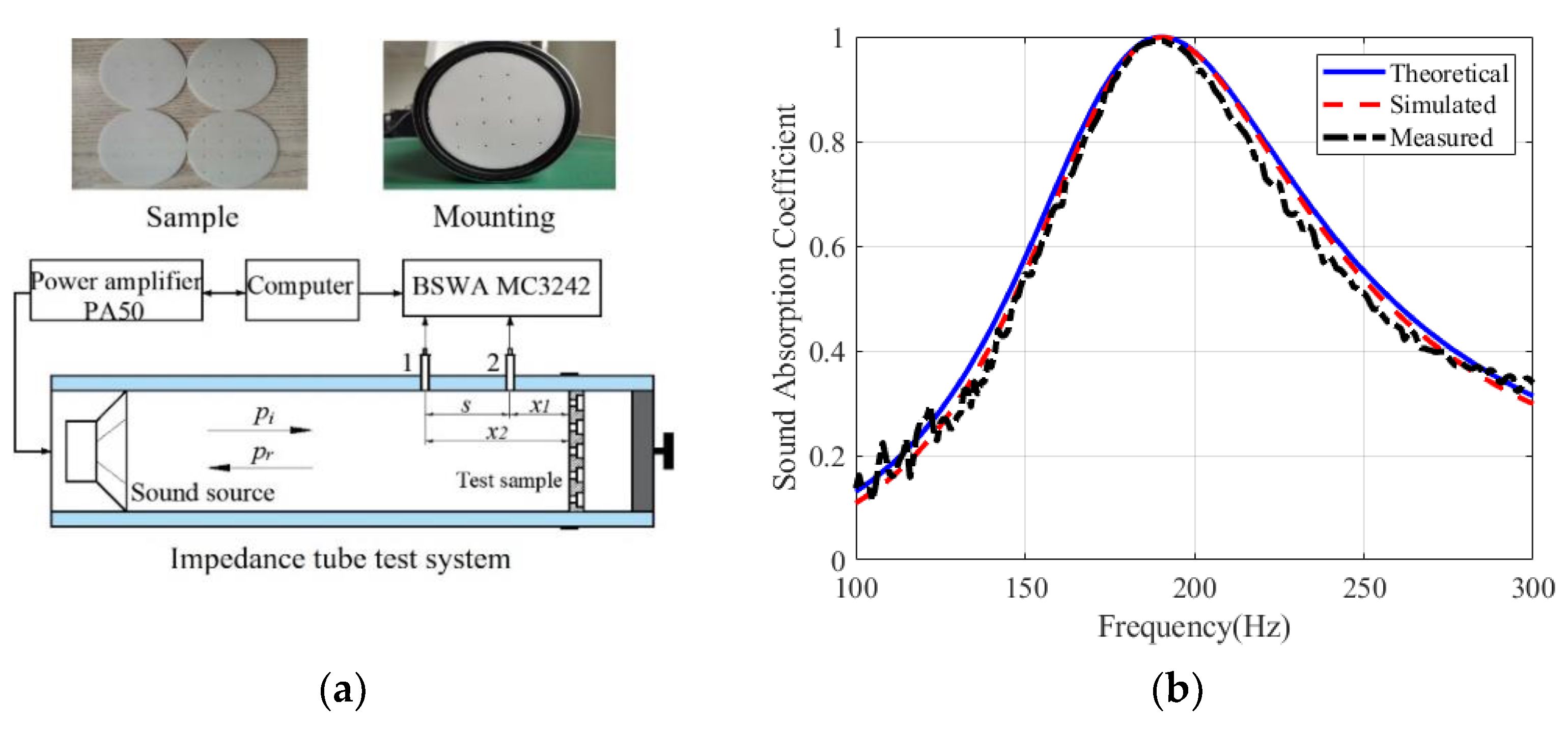
2.3. Experiment Measurements

To further verify the feasibility of the theoretical and numerical models, the sound absorption coefficients of PPSA absorber at normal incidence are measured by SW422 impedance tube with diameter of 100 mm, as shown in Figure 4a, and PPSA samples are made of resin materials by 3D printing using SLA (light curing molding) equipment. The outer diameter of the specimen is about 99 mm, so the sample is placed in the specimen tube with sealing strips or tape to ensure the tightness.
The sound absorption measurement in impedance tube follows the two-microphone transfer function method [30], and the principle is described below. The sound pressure p1 and p2 of two microphones located at position 1 and position 2 are expressed as:
p 1 = P I e j k 0 x 1 + P R e j k 0 x 1 , p 2 = P I e j k 0 x 2 + P R e j k 0 x 2
The transfer function of the incident wave and the reflected wave are written as:
H I = p 2 I p 1 I = e j k 0 ( x 1 x 2 ) = e j k 0 s , H R = p 2 R p 1 R = e j k 0 ( x 1 x 2 ) = e j k 0 s
According to Equation (13), the transfer function of the total sound field is denoted as:
H 12 = p 2 p 1 = e j k 0 x 2 + r e j k 0 x 2 e j k 0 x 1 + r e j k 0 x 1
Substituting Equation (14) into Equation (15), the reflection coefficient is expressed as:
r = H 12 H I H R H 12 e j 2 k 0 x 1
where x1 and x2 are the distances between microphone position 1 or position 2 and the front surface of the test sample, respectively, and s is the distance between two microphone position 1 and position 2. Once the reflection coefficient is determined, the sound absorption coefficient of the test sample can be calculated.
The sound absorption coefficients of a PPSA absorber in the frequency range of 100–300 Hz from theoretical, numerical and experimental results are plotted in Figure 4b. The parameters of the PPSA are d1 =1.5 mm, d1 =3 mm, t1 = 1 mm, t2 = 1 mm, p1 = 0.24%, p2 = 1.08% and the air cavity depth is D = 80 mm. The peak frequencies of three absorption coefficient curves are almost at 190 Hz, and the peaks are 0.999, 0.999 and 0.992, and the frequency ranges of absorption coefficients greater than 0.6 are 152–244 Hz, 153–242 Hz and 154–239 Hz, respectively. The results showed that there are tiny errors between the measured and predicted results. These unavoidable deviations may be due to factors such as machining accuracy and inaccurate mounting. In conclusion, the proposed theoretical and numerical models are feasible for predicting the sound absorption of the PPSA absorber. Meanwhile, it implies that the expected sound absorption is also relied on the accuracy of the sample processing.

3. Results and Discuss

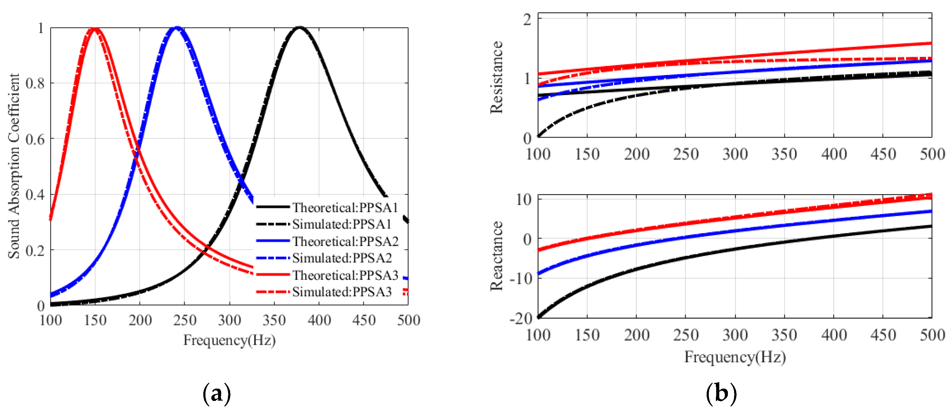
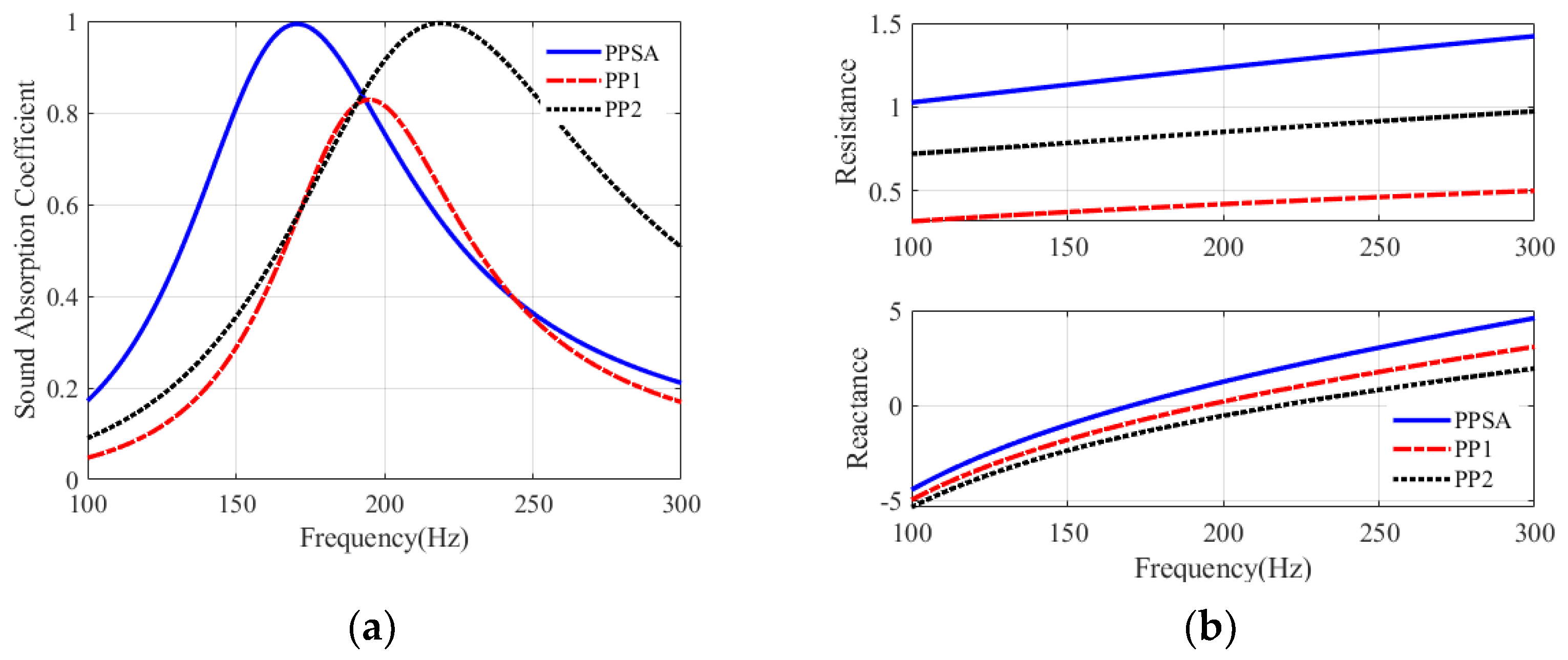
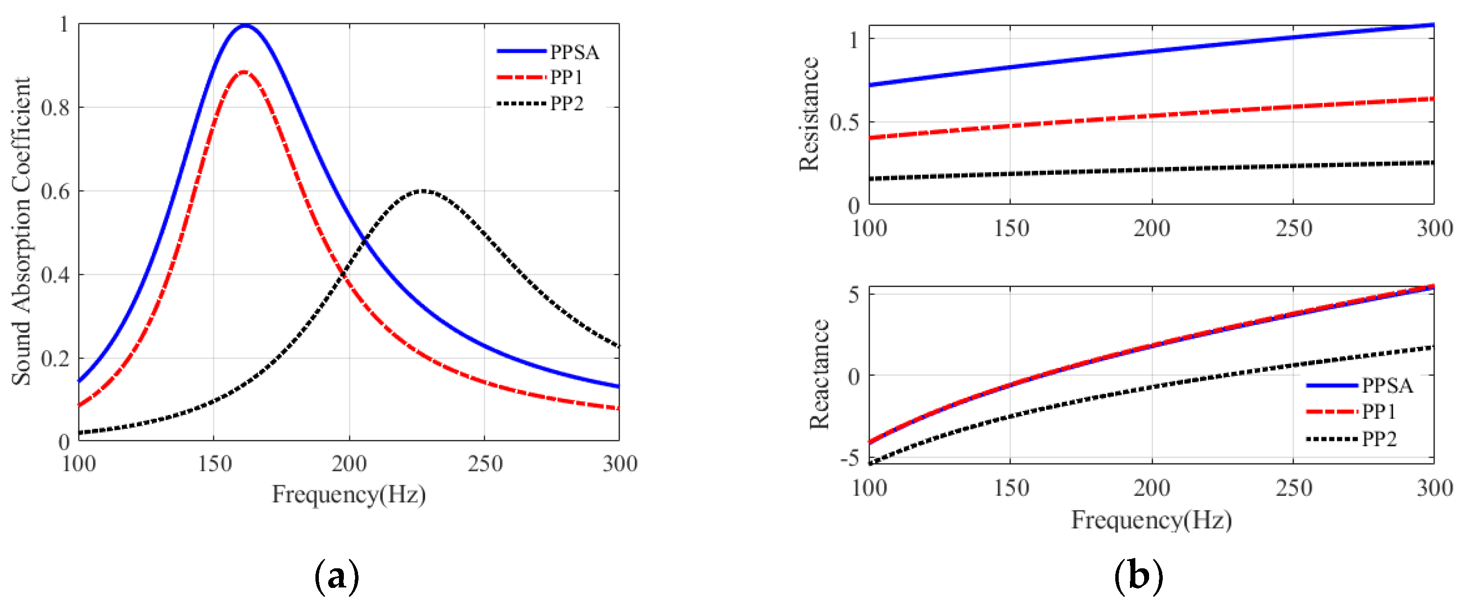
3.1. Sound Absorption of PPSA and Single Perforated Panle(PP) Absorber

To explain the feasibility of the proposed PPSA structure for low frequency sound absorption, comparisons of the sound absorption of PPSA absorber with that of single PP absorber are given here, with a depth of 80 mm for each air cavity. Figure 5 displays the theoretical sound absorption coefficients and acoustic impedance of PPSA and single PP absorbers with the same perforation ratio. The relevant parameters of PPSA and PP are listed in Table 2. In Figure 5a, the resonance peaks of PPSA, PP1 and PP2 absorber are located at 168 Hz, 195 Hz and 219 Hz, and the bandwidth of the sound absorption coefficient well above 0.6 are 76 Hz, 40 Hz and 110 Hz, respectively. In Figure 5b, PPSA has a relatively matched acoustic resistance from 1 to 1.41 in the range of 100–300 Hz. In contrast, the acoustic resistance of PP is extremely inadequate, especially the maximum acoustic resistance of PP1 with a large aperture is below 0.5. In addition, compared to the PP absorbers, the zero acoustic reactance of the PPSA absorber is shifted to a lower frequency. Even though, PP2 has a relatively large absorption bandwidth, its resonant frequency occurs at higher frequency, and a large number of perforations will increase the manufacturing costs. Thus, PPSA is more suitable for low-frequency sound absorption.
Figure 6 illustrated the theoretical sound absorption coefficients and acoustic impedance of PPSA and single PP absorbers with the same hole spacing. The parameters of PPSA and PP are given in Table 3. First, comparing PPSA and PP1, their resonant frequencies are close to 153 Hz and their sound reactance curves are almost overlapping as shown in Figure 6b. For PPSA with d1 = 2 mm and d2 = 4 mm, its thickness is t = 2 mm, while for PP1 with d = 4 mm, its thickness is 6.5 mm, thus the panel thickness of PPSA is about 3.25 times that of PP1. That is, for the same cavity depth and hole spacing, when PPSA and PP absorbers are resonating at the same frequency, PP with the large hole diameter requires a larger thickness. Meanwhile, the resonance peak of PPSA is close to 1, and that of PP1 is 0.88. The sound absorption coefficient of PPSA is greater than 0.6 from 135 Hz–196 Hz, and that of PP1 is greater than 0.6 from 143 Hz–182 Hz. Obviously, the sound absorption of PPSA is better than that of PP1. Furthermore, for PP2 of the thickness t = 2 mm, its resonance occurs at a higher frequency of 226 Hz with a peak of only 0.6. This is due to its inadequate acoustic resistance and high acoustic reactance. Therefore, the introduction of stepped holes not only effectively increase the acoustic resistance, but also shift the zero acoustic reactance of the PPSA absorber to lower frequencies.

3.2. Sound Absorption of PPSA Absorber with Varied Hole Spacing, Aperture and Plate Thickness

The theoretical absorption coefficients of the single PPSA absorber with varied hole spacing, aperture and plate thickness are marked with the color bar in Figure 7a–d. The parameters of PPSA are listed in Table 2 and hole spacing b = 30 mm, air cavity D = 80 mm. In Figure 7a, when other parameters remain unchanged, with the increase of hole spacing b, the effective sound absorption is distributed in the lower frequency range, and the maximum sound absorption coefficient reaches 1 and then decreases. In Figure 7b, when aperture d1 increases, the resonance shifts to higher frequencies and becomes weak, and the maximum sound absorption coefficient is significantly reduced. That is, when the perforation ratio is constant, the PPSA with a smaller aperture d1 is more conducive to sound absorption in the low frequency range. The effect of aperture d2 on the sound absorption is similar to that of aperture d1, so no explanation is given here. In Figure 7c, as the thickness t1 increases, the resonance occurs in the lower frequency, but the maximum sound absorption coefficient becomes lower. This is because the small aperture with a large thickness causes excessive damping. In Figure 7d, when the thickness t2 increases, the resonance also moves to lower frequencies, however, the maximum absorption coefficient of almost 1 is perfect in the whole range of t2. This is because for the large aperture, the sound mass changes obviously as the thickness increases, while the sound resistance changes relatively slightly. Therefore, proper parameters should be considered to obtain an effective PPSA absorber for low frequency sound absorption.

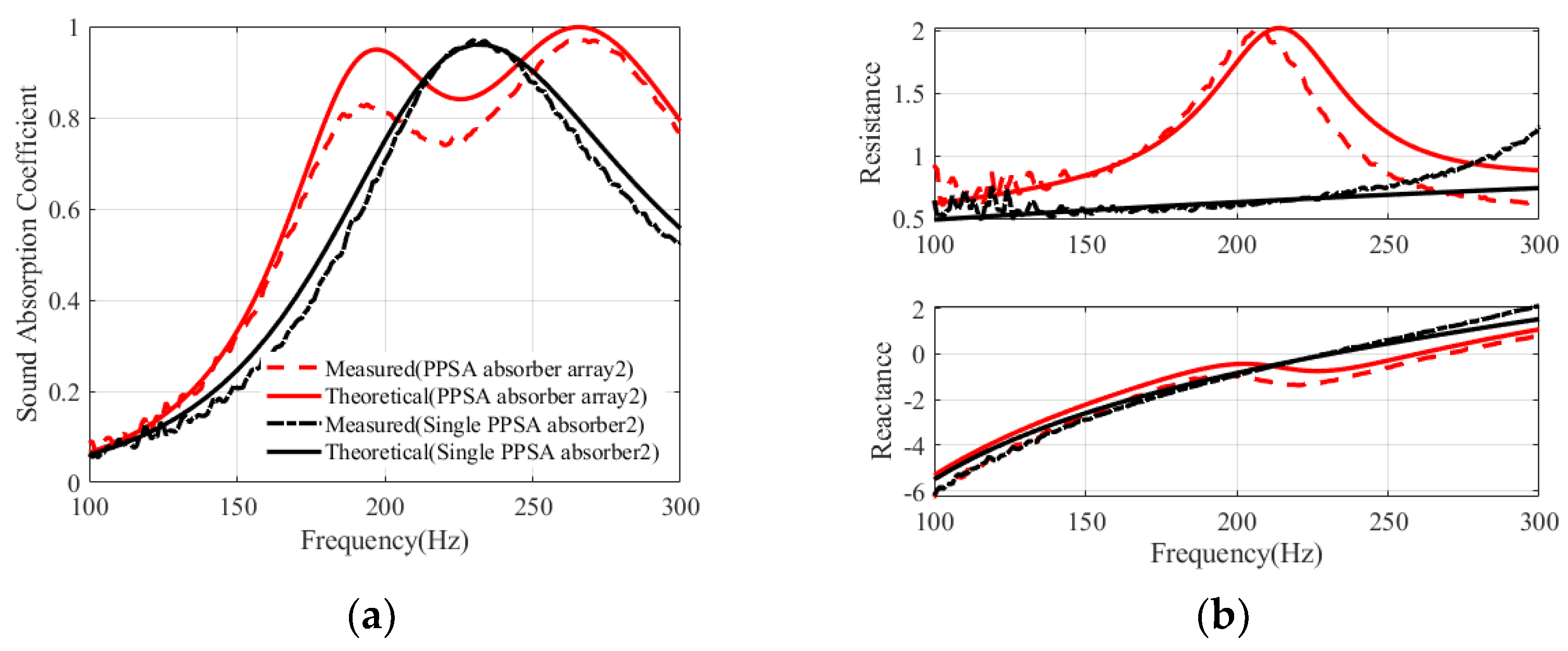
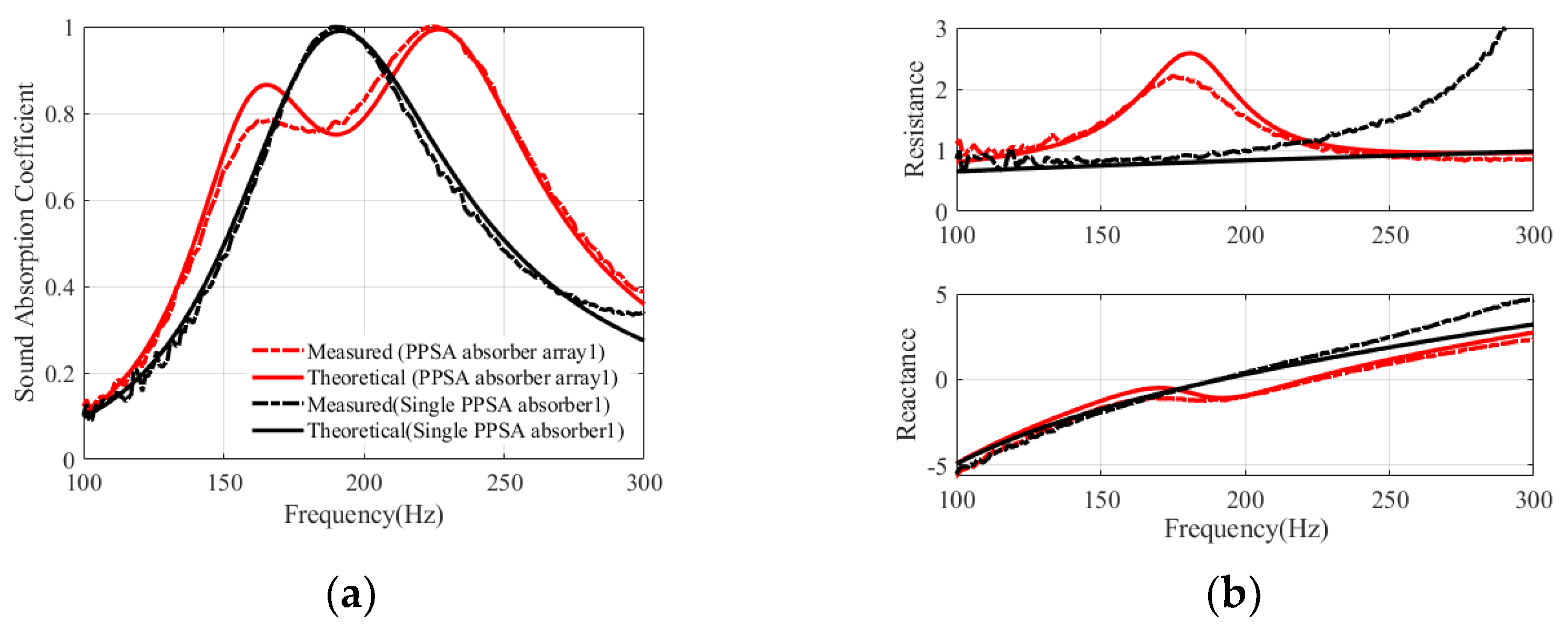
3.3. Sound Absorption of PPSA Absorber Array

Due to its Helmholtz resonance nature, PPSA absorber exhibits good sound absorption in the vicinity of the resonance. To further improve the sound absorption of PPSA absorber, only one rigid plate is inserted to separate the air cavities, thus introducing additional resonances to expand the absorption bandwidth, while the structural parameters of the PPSA remain unchanged.
Without loss of simplicity, a PPSA absorber array consisting of two sub-PPSA absorbers arranged in parallel is shown in Figure 8a. According to the electroacoustic analogy method, the surface impedance of the PPSA absorber array is expressed as:
Z = ( ϕ 1 Z 1 + ϕ 2 Z 2 ) 1
where φ1 and φ2 are the area ratios of sub-PPSA1 and sub-PPSA2 to the PPSA absorber array, Z1 and Z2 are the surface impedance of sub-PPSA1 and sub-PPSA2 absorbers, respectively.
Next, we will discuss the sound absorption performance of PPSA absorber array. As an example, a PPSA absorber array with panel thickness t = 2 mm, air cavity D = 100 mm, diameters of stepped hole d1 =1.5 mm and d2 = 4 mm, and its relevant parameters are listed in Table 4. The sound absorption coefficients of PPSA absorber array, sub-PPSA absorber and single PPSA absorber are demonstrated in Figure 8b. It can be observed that, the two peak of the PPSA absorber array are located at 158 Hz and 208 Hz, and the peaks of sub-PPSA1 and sub-PPSA2 absorber are positioned at 154 Hz and 213 Hz, respectively. That is, the two peaks of the PPSA absorber array are corresponding to those of sub-PPSA1 and sub-PPSA2 absorber, and the apparent frequency shift can be attributed to the interaction of sub-PPSA1 and sub-PPSA2. In addition, the PPSA absorber array has a sound absorption coefficient greater than 0.6 from 129 Hz to 257 Hz, and its sound absorption bandwidth is about 128 Hz. In contrast, the single PPSA absorber has a sound absorption coefficient greater than 0.6 from 150 Hz to 237 Hz, and its sound absorption bandwidth is about 87 Hz. Consequently, an array of PPSA absorbers can expand absorption bandwidth for low frequency under the common coupling effect of multi-local resonances.
Intuitively, Figure 8c shows the distribution of the normalized sound pressure and particle velocity at two absorption peak frequencies f = 158 Hz and f = 208 Hz. As observed, at f = 158 Hz, the sound pressure in the air cavity of sub-PPSA1 is approximately four times higher than that of the incident sound field, and most of the particle velocity flow is distributed in sub-PPSA1 absorber. Similarly, at f = 208 Hz, due to strong local resonance, the maximum sound pressure and particle velocity flow are mostly concentrated in the sub-PPSA2 absorber, and even the sound pressure does not change in the Sub-PPSA1. Thus, it is confirmed that acoustic energy is mainly dissipated by the local resonances of the PPSA absorber array.
For PPSA absorber array and single PPSA absorber, the measured and theoretical sound absorption of sample 1 and sample 2 are shown in Figure 9 and Figure 10, respectively. The air cavity depth of two samples is 80 mm, and the approximate parameters for samples are given in Table 5. There are some differences between the measured and the theoretical absorption coefficients, as well as the acoustic impedance, but their sound absorption characteristics are almost identical. For PPSA absorber array1, as shown in Figure 9a, the measured sound absorption coefficient is higher than 0.5 from 141 Hz to 280 Hz, and its effective sound absorption bandwidth is about 105 Hz. While for single PPSA absorber1, the measured sound absorption coefficient is above 0.5 from 153 Hz to 247 Hz, and its effective sound absorption bandwidth is about 59 Hz. Moreover, compared to a single PPSA absorber without partition, as observed in Figure 9b, the specific reactance of the PPSA absorber array changes relatively slowly and tends to 0, and its specific acoustic resistance is close to 1 except for the non-strong coupling domain of the sub-PPSA absorber.
Similarly, for PPSA absorber array2, as shown in Figure 10a, the measured sound absorption coefficient is higher than 0.5 from 165 Hz to 334 Hz, and its effective sound absorption bandwidth is about 129 Hz. While for single PPSA absorber2, the measured sound absorption coefficient is above 0.5 from 186 Hz to 302 Hz, and its effective sound absorption bandwidth is about 72 Hz. In addition, Figure 10b exhibits that the acoustic impedance characteristics of PPSA absorber array2 are the same as that of PPSA absorber array1. In summary, it is also demonstrated that the PPSA absorber array has the potential to enhance sound absorption compared to a single PPSA absorber. In addition, the overall dimensions of the fabricated specimens are 82 mm, which are only about 1/30th and 1/27th of the maximum wavelength of the semi-absorption coefficient, indicating that the PPSA absorber array is a compact structure for low frequency sound absorption.

4. Conclusions

In this paper, a PPSA absorber is studied to improve sound absorption for low frequencies. The advantages of the PPSA are that it matches acoustic resistance of air characteristic impedance and moderately increase acoustic mass by introducing stepped hole. The theoretical and numerical predictions agree well with the experimental results. In addition, an array consisting of two PPSA absorbers arranged in parallel is explored, and PPSA absorber array exhibits an effective broadband sound absorption due to the coupling effect of local resonances. The measured results also show that PPSA absorber array as a compact structure has the potential to control large wavelength noise in a limit space. Consequently, the proposed PPSA provides a meaningful method for the application of perforated plates in low frequency sound absorption. Moreover, in the subsequent work, we will investigate the sound absorption characteristics of the array structure of multiple inhomogeneous PPSA absorbers with different cavities.

Author Contributions

Conceptualization, X.L. and B.L.; methodology, data curation and investigation, X.L.; validation and software, C.Q.; resources and supervision, B.L.; writing—original draft preparation, X.L.; writing—review and editing, X.L. and C.Q. All authors have read and agreed to the published version of the manuscript.

Funding

The financial support given by NSFC with Grant No. 11874034 and Taishan Scholar Program of Shandong (No. ts201712054) are highly appreciated for this research.

Institutional Review Board Statement

Not applicable.

Informed Consent Statement

Not applicable.

Data Availability Statement

Not applicable.

Conflicts of Interest

The authors declare no conflict of interest.

References

  1. Yang, M.; Sheng, P. Sound Absorption Structures: From Porous Media to Acoustic Metamaterials. Annu. Rev. Mater. Res. 2017, 47, 83–114. [Google Scholar] [CrossRef]
  2. Liu, B.; Li, X. Noise transmission and absorption of lightweight structures: An overview and experience. In Proceedings of the 26th International Congress on Sound and Vibration, Montreal, QC, Canada, 7–13 July 2019. [Google Scholar]
  3. Callaway, D.B. The Use of Perforated Facings in Designing Low Frequency Resonant Absorbers. J. Acoust. Soc. Am. 1952, 24, 309–312. [Google Scholar] [CrossRef]
  4. Davern, W. Perforated facings backed with porous materials as sound absorbers—An experimental study. Appl. Acoust. 1977, 10, 85–112. [Google Scholar] [CrossRef]
  5. Allard, J.F.; Atalla, N. Porous Materials with Perforated Facings; Wiley: Hoboken, NJ, USA, 2009; pp. 187–212. [Google Scholar]
  6. Maa, D.Y. Theory and design of microperforated panel sound absorbing constructions. Science 1975, xviii, 55–71. [Google Scholar]
  7. Maa, D.-Y. Potential of microperforated panel absorber. J. Acoust. Soc. Am. 1998, 104, 2861–2866. [Google Scholar] [CrossRef]
  8. Randeberg, R.T. Perforated Panel Absorbers with Viscous Energy Dissipation Enhanced by Orifice Design. Ph.D. Thesis, NTNU, Trondheim, Norway, 2000. [Google Scholar]
  9. Sakagami, K.; Morimoto, M.; Yairi, M.; Minemura, A. A pilot study on improving the absorptivity of a thick microperforated panel absorber. Appl. Acoust. 2008, 69, 179–182. [Google Scholar] [CrossRef] [Green Version]
  10. Lu, W.; Zhang, B.; Li, X. Study on Acoustic Characteristic of Micro-Perforated Panel with Variable Cross-Section. Noise Vib. Control 2009. [Google Scholar] [CrossRef]
  11. Li-Yan, H.E.; Xi-Zhi, H.U.; Chen, T. The Influence of Variable Section of Orifice on Sound Absorption Characteristics of Thick Microperforated Panel. Noise Vib. Control 2011, 30, 141–144. [Google Scholar]
  12. Zhihui, M.A. Pilot Study on Simulations of Micro-Perforated Panel with Variable Cross-Section. Audio Eng. 2014, 3811–3813. [Google Scholar]
  13. Qian, Y.J.; Cui, K.; Liu, S.M.; Li, Z.B.; Kong, D.Y.; Sun, S.M. Numerical study of the acoustic properties of micro-perforated panels with tapered hole. Noise Control Eng. J. 2014, 62, 152–159. [Google Scholar] [CrossRef]
  14. Jiang, C.-S.; Li, X.-H.; Cheng, W.-Y.; Luo, Y.; Xing, T. Acoustic impedance of microperforated plates with stepwise apertures. Appl. Acoust. 2020, 157, 106998. [Google Scholar] [CrossRef]
  15. Li, D.; Chang, D.; Liu, B. Enhancing the low frequency sound absorption of a perforated panel by parallel-arranged extended tubes. Appl. Acoust. 2016, 102, 126–132. [Google Scholar] [CrossRef]
  16. Peng, X.; Ji, J.; Jing, Y. Composite honeycomb metasurface panel for broadband sound absorption. J. Acoust. Soc. Am. 2018, 144, EL255–EL261. [Google Scholar] [CrossRef] [Green Version]
  17. Liu, C.R.; Wu, J.H.; Chen, X.; Ma, F. A thin low-frequency broadband metasurface with multi-order sound absorption. J. Phys. D Appl. Phys. 2019, 52, 105302. [Google Scholar] [CrossRef] [Green Version]
  18. Long, H.; Shao, C.; Liu, C.; Cheng, Y.; Liu, X. Broadband near-perfect absorption of low-frequency sound by subwavelength metasurface. Appl. Phys. Lett. 2019, 115, 103503. [Google Scholar] [CrossRef]
  19. Li, X.; Wu, Q.; Kang, L.; Liu, B. Design of Multiple Parallel-Arranged Perforated Panel Absorbers for Low Frequency Sound Absorption. Materials 2019, 12, 2099. [Google Scholar] [CrossRef] [Green Version]
  20. Chen, J.-S.; Chen, Y.-B.; Cheng, Y.-H.; Chou, L.-C. A sound absorption panel containing coiled Helmholtz resonators. Phys. Lett. A 2020, 384, 126887. [Google Scholar] [CrossRef]
  21. Guo, J.; Zhang, X.; Fang, Y.; Jiang, Z. Wideband low-frequency sound absorption by inhomogeneous multi-layer resonators with extended necks. Compos. Struct. 2021, 260, 113538. [Google Scholar] [CrossRef]
  22. Cha, X.; Jian, K.; Zhang, T.; Zhou, X.; Fuchs, H. Application approach for microperforated panel sound absorbers. Acta Acustica 1994, 19, 258–265. [Google Scholar]
  23. Wang, C.; Huang, L. On the acoustic properties of parallel arrangement of multiple micro-perforated panel absorbers with different cavity depths. J. Acoust. Soc. Am. 2011, 130, 208–218. [Google Scholar] [CrossRef] [Green Version]
  24. Uenishi, K.; Okuzono, T.; Sakagami, K. Finite element analysis of absorption characteristics of permeable membrane absorbers array. Acoust. Sci. Technol. 2017, 38, 322–325. [Google Scholar] [CrossRef]
  25. Okuzono, T.; Uenishi, K.; Sakagami, K. Experimental comparison of absorption characteristics of single-leaf permeable membrane absorbers with different backing air cavity designs. Noise Control Eng. J. 2020, 68, 237–245. [Google Scholar] [CrossRef]
  26. Wu, T.; Cox, T.J.; Lam, Y.W. A profiled structure with improved low frequency absorption. J. Acoust. Soc. Am. 2001, 110, 3064–3070. [Google Scholar] [CrossRef] [Green Version]
  27. Lee, D.; Kwon, Y. Estimation of the absorption performance of multiple layer perforated panel systems by transfer matrix method. J. Sound Vib. 2004, 278, 847–860. [Google Scholar] [CrossRef]
  28. Crandall, I.B. Theory of Vibrating Systems and Sound, 2nd ed.; D. Van Nostrand Company: New York, NY, USA, 1927. [Google Scholar]
  29. Ingard, U. On the Design of Acoustic Resonators. J. Acoust. Soc. Am. 1953, 25, 830. [Google Scholar] [CrossRef]
  30. ISO (10534-2). Acoustics–Determination of Sound Absorption Coefficient and Impedance in Impedance Tubes–Part 2: Transfer-Function Method; 2001. [Google Scholar]
Figure 1. A perforated plate with stepwise apertures (PPSA) absorber. (a) Structure diagram; (b) One-dimensional acoustical system.
Applsci 11 06180 g001
Figure 2. Finite element simulation. (a) Thermos-viscous model of PPSA; (b) Pressure acoustic model of PPSA absorber.
Applsci 11 06180 g002
Figure 3. The theoretical and simulated results for PPSA absorbers. (a) Sound absorption coefficients; (b) Specific acoustic impedance.
Applsci 11 06180 g003
Figure 4. Experimental setup and results. (a) Impedance tube system and test sample; (b) Absorption coefficients of PPSA absorber from three models: theoretical, FEM and experimental.
Applsci 11 06180 g004
Figure 5. Sound absorption of PPSA and single PP absorbers with the same perforation ratio. (a) Sound absorption coefficients; (b) Specific acoustic impedance.
Applsci 11 06180 g005
Figure 6. Sound absorption of PPSA and single PP absorbers with the same hole spacing. (a) Sound absorption coefficients; (b) Specific acoustic impedance.
Applsci 11 06180 g006
Figure 7. The sound absorption coefficients of PPSA absorber with varied structure parameters. (a) Hole spacing b; (b) Hole aperture d1; (c) Plate thickness t1 of the small aperture; (d) Plate thickness t2 of the large aperture.
Applsci 11 06180 g007
Figure 8. PPSA absorber array. (a) Structure diagram; (b) Sound absorption coefficients; (c) The acoustic pressure field (color map) and velocity distribution (yellow arrow).
Applsci 11 06180 g008
Figure 9. The sound absorption of Sample 1. (a) The measured and theoretical sound absorption coefficients; (b) The measured and theoretical specific acoustic impedance.
Applsci 11 06180 g009
Figure 10. The sound absorption of Sample 2. (a) The measured and theoretical sound absorption coefficients; (b) The measured and theoretical specific acoustic impedance.
Applsci 11 06180 g010
Table 1. Parameters for three PPSA absorbers in the theoretical and simulated comparison.
Parameters PPSA1PPSA2PPSA3
d(d1/d2) (mm)1.5/41.5/41.5/4
t(t1/t2) (mm)1/11/11/1
σ(σ1/σ2) (%)0.27/1.920.23/1.600.18/1.28
D (mm)2550100
Table 2. Parameters for PPSA and single PP absorbers with the same perforation ratio.
Parameters PPSASingle PP1Single PP2
d(d1/d2) (mm)1.5/331.5
t(t1/t2) (mm)1/122
σ(σ1/σ2) (%)0.21/0.811.021.02
Table 3. Parameters for PPSA and single PP absorbers with the same hole spacing.
Parameters PPSA Single PP1 Single PP2
d(d1/d2) (mm)2/444
t(t1/t2) (mm)272
b (mm)39.639.639.6
Table 4. Parameters for PPSA absorber array and single PPSA absorber.
Parameters PPSA Absorber Array Single PPSA
Absorber
Sub-PPSA1 Sub-PPSA2
d(d1/d2) (mm)1.5/441.5/4
t(t1/t2) (mm)1/11/11/1
σ(σ1/σ2) (%)0.095/0.670.185/1.3150.28/1.98
Table 5. Parameters of Samples of PPSA absorber array and single PPSA absorber.
Sample 1
Parameters
PPSA Absorber Array1Single PPSA
Absorber1
Sub-PPSA1Sub-PPSA2
d(d1/d2) (mm)1.8/31.8/31.8/3
t(t1/t2) (mm)1/11/11/1
σ(σ1/σ2) (%)0.095/0.270.195/0.540.29/0.81
Sample 2
Parameters
PPSA absorber array2Single PPSA
Absorber2
Sub-PPSA1Sub-PPSA2
d(d1/d2) (mm)1.8/3.81.8/3.81.8/3.8
t(t1/t2) (mm)1/11/11/1
σ(σ1/σ2) (%)0.14/0.6150.275/1.230.415/1.845
Publisher’s Note: MDPI stays neutral with regard to jurisdictional claims in published maps and institutional affiliations.

