Featured Application
This paper strengthens the mechanical property by managing manufacturing strategy in the Fused Filament Fabrication (FFF) process. Without consuming high-expense continuous carbon fiber material, this isotropy toolpath would improve the components’ functionally of the FFF process and enlarge the application area of the thermoplastic print.
Abstract
The fused filament fabrication (FFF) process deposits thermoplastic material in a layer-by-layer manner, expanding the design space and manufacturing capability compared with traditional manufacturing. However, the FFF process is inherently directional as the material is deposited in a layer-wise manner. Therefore, the in-plane material cannot reach the isotropy character when performing the tensile test. This would cause the strength of the print components to vary based on the different process planning selections (building orientation, toolpath pattern). The existing toolpaths, primarily used in the FFF process, are linear, zigzag, and contour toolpaths, which always accumulate long filaments and are unidirectional. Thus, this would create difficulties in improving the mechanical strength from the existing toolpath strategies due to the material in-plane anisotropy. In this paper, an in-plane isotropy toolpath pattern is generated to enhance the mechanical strength in the FFF process. The in-plane isotropy can be achieved through continuous deposition while maintaining randomized distribution within a layer. By analyzing the tensile strength on the specimens made by traditional in-plane anisotropy toolpath and the proposed in-plane isotropy toolpath, our results suggest that the mechanical strength can be reinforced by at least 20% using our proposed toolpath strategy in extrusion-based additive manufacturing.
1. Introduction
The fused filament fabrication (FFF) process uses a heat-up nozzle to liquefy the thermoplastic material and deposit it in a layer-wised manner. Though it is being developed for decades and extends the manufacturability and design space compared with traditional manufacturing, the inconsistent and unsatisfactory mechanical properties of the build still hinder it from being accepted by major industries beyond the prototyping stage. With the requirement of being a functional part, mechanical strength is essential but difficult to control in the FFF process. The current workflow (Figure 1) in the FFF process generates the build plan for a given 3D model. The build outcomes heavily rely on the manual setup of the process variables in the process planning stage.
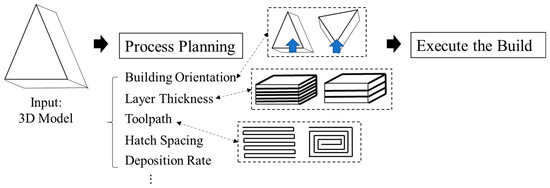
Figure 1.
Workflow for AM builds preparation.
A large variety of process variables—hatch spacing, building orientation, and extrusion rate—could control and optimize the process outcome, such as the mechanical strength. Table 1 provides an overview of the current strategy of enhancing mechanical strength by mainly focusing on optimizing process parameters and hybridizing different toolpath strategies.

Table 1.
Optimization Strategies in FFF processes.
Table 1 presents the current methods to enhance process qualities in terms of build time, surface finish, and mechanical strength by varying process parameters, such as layer thickness, printing speed, and processing environment. However, the analysis of the fabrication strategy for the deposition path is not being studied. All of the above-mentioned studies mainly utilize the common linear/contour toolpath. However, these toolpath strategies will cause long filaments to pile in a parallel manner in a plane. Ultimately, this can cause the material to display anisotropic behavior. Thus, such in-plane anisotropy would induce poor mechanical strength.
Besides the effect from process parameters and working environments, the leading causes of insufficient strength are low infill density, weak interfacial bonding, and in-plane anisotropy of the material [9,10]. These physical phenomena are significantly influenced by the toolpath strategy and can be optimized by altering manufacturing strategy to achieve a desired mechanical strength. Studies reveal that higher density can lead to a stronger component; thus, a 100% solid infill is desired in our research to enhance the mechanical strength. In order to achieve a 100% density infill, two major toolpaths are commonly used in today’s FFF process—the linear and contour toolpath [11]. Other existing toolpaths, such as honeycomb, triangle, cubic, and Gyroid [12], are hard to achieve a solid infill for any given geometry. All of the above-mentioned toolpath strategies can fulfill 100% infill. However, the homogeneously laminated filament bars can cause the in-plane anisotropy material property [13].
Considering the material deposition manner, the manuscript targets to provide a material deposition strategy to achieve the in-plane isotropy, ultimately improving the mechanical strength. Existing techniques in improving mechanical strength regarding altering toolpath can be classified as bio-inspired structures and non-planar toolpaths. Bio-inspired structures such as honeycomb [14], cross-linked [15], and Bouligand structures [16,17] have been studied to improve mechanical properties. In addition, the other strategies by altering the toolpath to reduce the in-plane anisotropic property caused by longitudinal filament are shown in Figure 2. These strategies are mostly adopted in metal AM processes for reducing the thermal distortion by evenly distributing the heat. However, the continuity of the in-plane filament cannot be maintained through these.
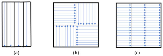
Figure 2.
Existing strategies of handling anisotropy created by longitudinal filament, (a) adaptive toolpath width [18], (b) island toolpath strategy [19], (c) hatch parallel toolpath strategy [19].
Compared with these structures, our proposed in-plane isotropy toolpath can achieve a solid component in a more flexible filament arrangement to reduce the in-plane void region and increase mechanical strength at the same time. Recently, several researchers [20,21] studied the rotational angle per layer to improve the mechanical properties; however, the rotational angle can create voids on the 2D geometry based on the deposited filament shape, which can further induce the unsatisfactory mechanical properties. The non-planar toolpath [11,22] effect towards improving mechanical strength is still ambiguous; the non-planar layer creation and modeling towards better print performance are not developed. In this research, an isotropy in-plane material deposition strategy is provided to fulfill the solid density with strong interfacial bonding. Our developed toolpath strategy is targeting to achieve a randomized material distribution in one layer while maintaining the material deposition in a continuous manner. The proposed toolpath generation workflow is presented in Figure 3.
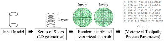
Figure 3.
Workflow of generating in-plane isotropy toolpath.
The input model is first sliced into layers, and each layer will be filled with a continuous toolpath. The toolpath on each layer shows a randomized pattern without intersection and varied per layer. This character can provide:
- Non-longitudinal filaments lie along one direction accumulate that induce structural anisotropy.
- A dissimilar toolpath per layer can fill up the void created by the filament (Figure 4).
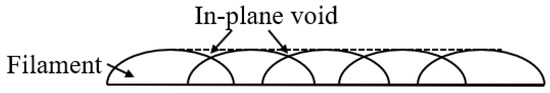 Figure 4. The deposited filament creates in-plane voids.
From Figure 3, we can see that the semi-sphere shape of the deposited filament creates a unflatten top surface on each layer. This uneven surface induces the in-plane void, which may affect the component’s mechanical properties. If using a parallel toolpath in the adjacent layers, these in-plane voids would introduce the porosity in the final build. Thus, different toolpath on adjacent layers can fill these voids, thus increase the mechanical properties.
In this paper, an in-plane isotropy toolpath is proposed to increase the mechanical strength of the thermoplastic part. Under the same printing conditions (print speed and environment), the specimens built by the proposed toolpath are compared with traditional in-plane anisotropy fabrication strategies (linear and contour) using uniaxial tensile tests to validate the effectiveness of the strengthening. With this method, the tensile strength can be improved at least 20% without additional post-processing or material treatment. This can enhance the mechanical strength and assure the print quality by using an applicable, low-cost strategy.
2. Literature Review
2.1. Toolpath for FDM
Currently, linear and contour toolpath strategies (See Figure 5) are the most widely adopted for FFF processes. Both toolpaths share the paralleling character, which creates the accumulation of parallel longitudinal filaments. The other toolpath for minimizing building time and maximizing continuous motion is discussed as follows.
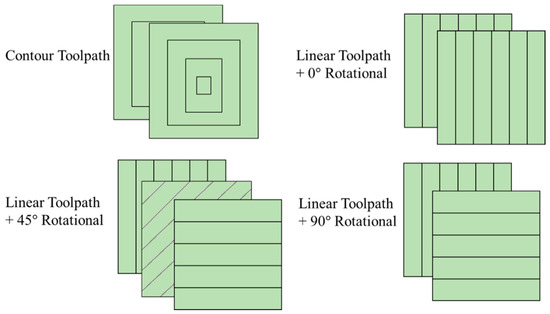
Figure 5.
Linear and contour toolpaths in a square.
Papacharalampopoulos et al. [23] proposed a Hilbert curve as the path pattern for continuous printing that ensures a single motion. In addition, Zhai and Chen [24] introduced a porous path planning strategy for the porous structures in the FFF process. It can optimize the fabrication time for porous structures. With a similar goal, Jin et al. [25] developed a non-printing strategy that avoids retraction in the FFF process. Thus, traveling without material extrusion can be saved. In parallel, a combined heuristic path planning method was proposed by Volpato et al. [26] to reduce the overall traveling distance, thus minimizing total building time.
Weidong [27] presents a genetic algorithm on C paths, while Wah et al. [28] use the same strategy to optimize the deposition sequence locally. In addition, idling time optimization is another research topic in the FFF process [4,29]. Dreifus et al. [4] proposed a graph-theoretical approach to minimize the overall traveling time on the building platform. Lensgraf [29] decompose the layers into local islands and minimizing the traveling time among the islands using the greedy method.
2.2. Strategies for Enhancing Mechanical Strength
To date, several studies have investigated the process parameters’ impacts on mechanical strength, such as building orientation, rotational angle per layer, filament deposition direction [30,31,32,33,34,35,36]. The common conclusion is to obtain a maximum strength is to keep the filament deposition orientation along the pulling direction. In addition, effects from extrusion rate and layer thickness are commonly studied [37,38,39,40,41]. However, the layer thickness is still a controversial parameter which varied results are concluded. In the meantime, increasing the feed rate could decrease the tensile strength [40,41]. There are limitations of the strategies mentioned above to improve the build quality as listed:
- Process parameters (building orientation, layer thickness, extrusion rate, hatch spacing…) are highly correlated. The individual adjustment on a single parameter would cause an unexpected quality change
- Lack of quantitative relationship between process parameters and process outcomes (mechanical properties), the modification of the process parameters becomes more challenging
Unlike any of the previous approaches mentioned, the method introduced by Panda [42] involves the study of organic material as it aims to optimize the FDM process. This method is referred to as the Bacterial Foraging Optimization Algorithm (BFOA) and operates on the social and symbiotic relationships found in nature between organisms. Rodriguez [43] make the argument that utilization of computational tools and algorithms allows for a better comprehension of the strengths of the layers and fibers of the part. The magnitude of this strength can be significantly altered by the orientation of the build for each part. Thus, the utilization of computational algorithms to find this desired orientation is crucial to the FDM process. Besides, Avdeev et al. [44] create a cylinder inside any given geometry and deposit a spiral toolpath upon the cylinder surface to increase the strength of the build. Some other studies on optimization on the deposition toolpath improve the product qualities [27,28].
Other methods, such as adding nanoparticles [45] or additional post-processing [46], can also improve mechanical properties. For example, Deng et al. [47] used a new polymer such as PEEK to strengthen the 3D printed parts of physical and chemical properties. Duty et al. [48] also presented extruding the same material (Z-pinning) in the structure to reinforce the element. Some other toolpaths are planar/non-planar to improve mechanical strength [22,23,49]. Akkum et al. [49] proposed a ZigZagZ toolpath that creates a zigzag pattern across the layers to increase the Z-axis strength. In addition, Xiao [22,50] utilized the multi-axis slicing and curved layers to improve the part strength in a support-less manner. Altering the manufacturing strategy can enhance the mechanical strength, but using continuous carbon fiber [51] can also increase the print mechanical properties. However, the equipment and the material are relatively expensive compared with PLA or other thermoplastic materials.
3. Materials and Methods
The proposed in-plane isotropy toolpath strategy will be introduced in this section, along with the experiment set up for testing the tensile strength. The dogbone-shaped specimens were chosen for all pieces, and the tensile strength was evaluated for all prints to prove the effectiveness of the proposed toolpath strategy.
3.1. Path Design
This section presents a detailed explanation of constructing the in-plane isotropy toolpath by randomizing the XY-plane vector toolpath. In the meantime, the in-plane toolpath maintains a continuous deposition path that avoids the filament’s potential discontinuity that causes the low strength. In addition, each layer generates a different toolpath pattern, which reduces the possibility of creating porosity. Finally, the proposed toolpath performance is compared with linear, linear with rotational angle, contour toolpath strategies printed under the same layer thickness.
Algorithm 1 presents the in-plane isotropy toolpath generation by randomizing the vector toolpath and avoiding the intersection. Since continuous and randomized deposition is the desired in-plane manufacturing strategy, the toolpath generation should follow the prerequisites. The toolpath for randomized deposition can be easily determined; however, such randomized path planning can create collision and intersection of these paths. Algorithm 1 first determines a straight path with n nodes that allows being expanded later. These n nodes can be allocated with a random vector to re-allocate their position, the connection between connecting nodes will be updated. These updated paths will keep expanding until the whole area of the 2D sliced geometry is fulfilled.
| Algorithm 1: Generation of in-plane isotropy toolpath. |
| Input: Any given 3D model, Building Orientation, Layer thickness, loading direction |
| Output: Series of layer-wised toolpath |
| 1. 3D model = |
| 2. = max_length () along with tensile test loading direction |
| 3. Initialize n particles on , allow norm () = length()/n |
| 4. |
| 5. |
| 6. max = boundary() |
| 7. Initialize n particles with randomized vector |
| 8. new() = |
| 9. Update |
| 10. End until boundary () = max |
For any given 2D geometry, the toolpath satisfies the following condition:
- ,
Since the toolpath width is not uniform in the proposed the vectorized toolpath from Algorithm 1, the extrusion rate for the process input is necessary. Algorithm 2 shows the deposition volume along the path, and the deposition volume can then be converted to the extrusion rate.
| Algorithm 2: Generation of Process Parameters. |
| Input: Output from Algorithm 1, Printing velocity (v), layer thickness (LH) |
| Output: Extrusion Rate |
| 1. Vectorize in-plane toolpath to {[], [],…, []} |
| 2. |
| 3. |
| 4. Construct |
| 5. L = min() |
| 6. |
| 7. |
The extrusion rate, which varies with traveling time to maintain the minimum pores for the proposed toolpath is introduced in Algorithm 2. We can easily calculate the path volume between connecting nodes on the continuous path based on the desired path width, distance, and layer height. However, this path volume is not a constant value for the proposed continuous isotropy toolpath. Thus, the extrusion rate needs to be varied for such traveling to maintain the least amount of pores that the path planning could potentially introduce.
3.2. Experiments
In this work, all specimens are printed with a uniform layer thickness at a printing speed = 30 mm/s. Different specimens choose varied layer thickness with traditional (linear and contour) and proposed isotropy toolpath strategies. The process parameters of traditional toolpaths for comparison with the proposed toolpath are shown in Table 2, and these parameters stay constant during the build. The printed specimen dimension is shown in Figure 6 with a total thickness = 3.302 mm. Five specimens are printed using each printing strategy; the average ultimate tensile test results with the standard deviations are shown in Section 4.
Table 2.
Process Parameters that are used in experiments.
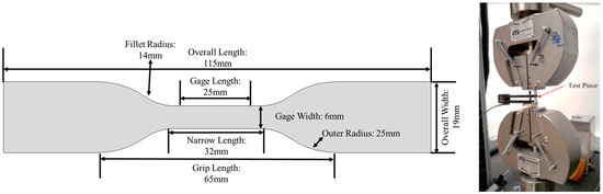
Figure 6.
Test specimen (ASTM D638 IV) and test setup for tensile stress.
All of the test specimens (dog bone samples) were printed (Figure 6, left) using Ender Pro 3 using polylactic acid (PLA) material (by HATCHBOX with 1.75 mm diameter) and are tested on Instron (Figure 6 right) with the indicated setup. It is conducted under the standard temperature around 23 ± 2 °C (73.4 ± 3.6 °F), and also maintains the relative humidity at 50 ± 5%. The rate of grip separation operates at 50 mm/min.
4. Results
In this section, fractured specimens (layer thickness = 0.2mm) are presented in Figure 7, with the geometry of each fracture surface. Compared among these printed specimens, the proposed toolpath specimen has a shear crack that behaves better.
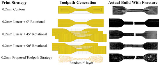
Figure 7.
Fractured dogbone specimens at layer thickness = 0.2mm.
From Figure 7, we can see that all PLA specimens by using traditional linear toolpath crack under the tensile test. The contour toolpath specimen did not crack, but each path has necking. The bonding between each parallel path is weak, thus resulting in the failure. However, the specimen which is fabricated using the proposed toolpath has a shear crack. This implies the specimen developed tangential displacement, thus resulting in a better ultimate tensile strength. The load extension graphs of all printed specimens are shown in Figure 8 and Figure 9. In general, specimens with proposed in-plane isotropy toolpaths present better tensile strength than all traditional paths. The ultimate tensile strength of all printed specimens is shown in Table 3.
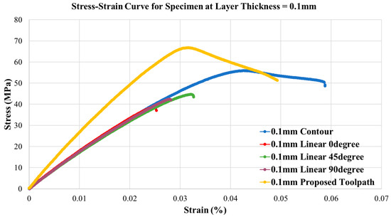
Figure 8.
Load extension graph for all print specimens at layer thickness = 0.1 mm.
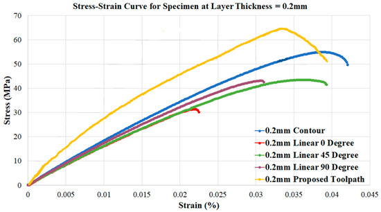
Figure 9.
Load extension graph for all print specimens at layer thickness = 0.2 mm.
Table 3.
Tensile strength test results of printed specimens (each print of the same strategy repeats five times).
Figure 8 and Figure 9 indicate the proposed toolpath strategy can successfully increase the tensile strength compared with the same layer thickness specimens. The ultimate tensile strength can be improved by at least 19% compared to the traditional contour toolpath. In the meantime, the proposed toolpath would lead to a minimum extension before the fracture.
Table 3 shows the average of ultimate tensile strength for all printed specimens at each printing strategy; the proposed toolpath shows a 20% increase in the tensile strength compared with the other specimens under the same layer thickness condition. From Table 3, we can see that the Young’s Modulus for the proposed toolpath specimen yields at least 1.3 times than the other traditional toolpath specimen. Therefore, the proposed toolpath can result in a higher modulus and a denser component. The higher ductility of the proposed manufactured components also indicates the lower voids fraction than the traditionally manufactured specimens. The relative density of each specimen is obtained. This also indicates the tensile strength is correlated with relative density. The proposed toolpath generates a higher density component, thus creating a strengthened geometry.
Figure 10 presents all print specimens with each printing strategy with their average ultimate tensile strengths and associated standard error bars. From this figure, we can see that the 0.1-mm layer thickness can strengthen the part of the 0.2-mm layer thickness. However, such layer thickness effect is not significant on the printed specimens using the proposed toolpath. This further proves the proposed toolpath can create a stronger tensile property, disregards the layer thickness.
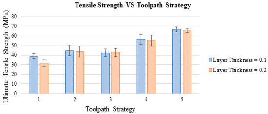
Figure 10.
Tensile strength measurements based on different printing strategies.
To verifying the significance level of each variable to the tensile strength, an ANOVA analysis of variance (Table 4) is conducted for “layer thickness” and “toolpath strategy” factor with “tensile strength” as the response. The “rotational angle” is not included in this study because the contour and proposed toolpath do not have any rotational angle value. From Table 4, the P-value for toolpath strategy is 0.001<0.005, which means that the toolpath strategy is a significant factor for the tensile strength in the Fused Filament Fabrication process.
Table 4.
ANOVA Analysis on the Layer Thickness and Toolpath Strategy.
Table 3 and Figure 10 show that the specimens printed with contour toolpath strategy at 0.1 mm and 0.2 mm show a better tensile strength and a higher density component compared with other specimens printed with the traditional linear toolpath even with a rotational angle. However, the specimen with the proposed toolpath that is printed with a 0.1-mm layer thickness behaves a 19.49% larger tensile strength than the 0.1-mm layer thickness specimen with a contour toolpath. The tensile test of the specimen with the proposed toolpath that is printed at a 0.2-mm layer thickness performs similarly.
Fracture surfaces of the tested specimens are obtained by an optical microscope (Leica DM2700 M) under the operating temperature around 23 ± 2 °C (73.4 ± 3.6 °F), and maintain the relative humidity at 50 ± 5%. The morphologies of the specimens with a 6&10 fracture are shown in Figure 11. The morphology of the finished surface on the specimens is presented as well. From Figure 11 (left), there is a clear cut at each path on the specimen. This is because the ultimate tensile strength happens at the maximum loading that such longitudinal filament can bear. Compared with Figure 11 right, which is fabricated through our proposed toolpath, there is no clear cut at the fracture surface, and the morphology of the finished surface shows no clear traveled paths. The traditional toolpath can be represented as the longitudinal filament bonded in parallel, and the fracture will happen at the perpendicular cross-section of these filament laying directions. As a result, the displacement develops collinearly to the filament deposition direction. However, the proposed toolpath does not have such longitudinal filament bonding issues, and the morphology shows the fracture appears not at the perpendicular cross-section of the filament laying direction. Thus, the target for minimizing the longitudinal filament accumulation is achieved.
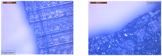
Figure 11.
Microscope of the fracture of specimen 6 (left) & 10 (right).
5. Conclusions and Discussion
In this paper, an in-plane isotropy toolpath is developed for the extrusion-based FFF process. The path is designed to minimize longitudinal filament accumulation, thus reducing the in-plane anisotropy that unbalances the strength in the XY plane. Tensile tests with varied layer thicknesses confirm the increase of the tensile strength. This result indicates that the rotational angle can optimize the tensile strength using a traditional linear toolpath, while the contour toolpath can achieve the maximum tensile strength for the build. Compared with those specimens with traditional toolpath strategies, the tensile strength can be improved by at least 20%. Furthermore, the proposed toolpath behaves with a stronger mechanical strength and with a higher modulus; the better ductile property also indicates the specimens with the proposed toolpath have lower voids fraction ratios.
This paper presents a toolpath that minimizes the anisotropy material distribution in the XY plane and can improve the mechanical strength of the build by randomized the material distribution in the planar layer while maintaining the continuous deposition manner. The effectiveness of the proposed fabrication strategy is shown by analyzing the tensile strength of different toolpaths under the same printing condition. However, the layer-by-layer material deposition manner still introduces the bonding between the layers, which may cause anisotropy material property in the 3D space. Therefore, the toolpath strategy in the 3D space that can minimize the bonding effects needs to be discussed in the future to create a part with isotropic material property throughout the whole geometry. In addition, the impact from the process parameters, such as printing speed and layer thickness, will be considered in discussing the isotropy toolpath in the future.
Author Contributions
Conceptualization, X.X. and B.-M.R.; methodology, X.X.; software, X.X.; validation, X.X., and B.-M.R.; formal analysis, X.X., B.-M.R.; investigation, X.X., F.Z.; resources, X.X.; data curation, B.-M.R.; writing—original draft preparation, X.X., B.-M.R.; writing—review and editing, X.X., B.-M.R., F.Z.; visualization, X.X., B.-M.R. All authors have read and agreed to the published version of the manuscript.
Funding
This research received no external funding.
Institutional Review Board Statement
Not applicable.
Informed Consent Statement
Not applicable.
Data Availability Statement
Data is contained within the article.
Conflicts of Interest
The authors declare no conflict of interest.
References
- Jin, Y.-A.; He, Y.; Xue, G.-H.; Fu, J.-Z. A parallel-based path generation method for fused deposition modeling. Int. J. Adv. Manuf. Technol. 2015, 77, 927–937. [Google Scholar] [CrossRef]
- Volpato, N.; Zanotto, T.T. Analysis of deposition sequence in tool-path optimization for low-cost material extrusion additive manufacturing. Int. J. Adv. Manuf. Technol. 2018, 101, 1855–1863. [Google Scholar] [CrossRef]
- Castelino, K.; D’Souza, R.; Wright, P.K. Toolpath optimization for minimizing airtime during machining. J. Manuf. Syst. 2003, 22, 173–180. [Google Scholar] [CrossRef]
- Dreifus, G.; Goodrick, K.; Giles, S.; Patel, M.; Foster, R.M.; Williams, C.; Lindahl, J.; Post, B.; Roschli, A.; Love, L.; et al. Path optimization along lattices in additive manufacturing using the chinese postman problem. 3D Print. Addit. Manuf. 2017, 4, 98–104. [Google Scholar] [CrossRef]
- Lensgraf, S.; Mettu, R.R. An improved toolpath generation algorithm for fused filament fabrication. In Proceedings of the 2017 IEEE International Conference on Robotics and Automation (ICRA), Singapore, 29 May–3 June 2017; pp. 1181–1187. [Google Scholar]
- Gurrala, P.K.; Regalla, S.P. Part strength evolution with bonding between filaments in fused deposition modelling: This paper studies how coalescence of filaments contributes to the strength of final FDM part. Virtual Phys. Prototyp. 2014, 9, 141–149. [Google Scholar] [CrossRef]
- Sun, Q.; Rizvi, G.M.; Bellehumeur, C.T.; Gu, P. Effect of processing conditions on the bonding quality of FDM polymer filaments. Rapid Prototyp. J. 2008, 14, 72–80. [Google Scholar] [CrossRef]
- Pandey, P.; Reddy, N.; Dhande, S. Real time adaptive slicing for fused deposition modelling. Int. J. Mach. Tools Manuf. 2003, 43, 61–71. [Google Scholar] [CrossRef]
- Chacón, J.M.; Caminero, M.A.; García-Plaza, E.; Núñez, P.J. Additive manufacturing of PLA structures using fused deposition modelling: Effect of process parameters on mechanical properties and their optimal selection. Mater. Des. 2017, 124, 143–157. [Google Scholar] [CrossRef]
- Khosravani, M.R.; Reinicke, T. Effects of raster layup and printing speed on strength of 3D-printed structural components. Procedia Struct. Integr. 2020, 28, 720–725. [Google Scholar] [CrossRef]
- Tam, K.-M.M.; Mueller, C.T. Additive manufacturing along principal stress lines. 3D Print. Addit. Manuf. 2017, 4, 63–81. [Google Scholar] [CrossRef]
- Ultimaker.Com. Ultimaker Cura: Powerful, Easy-to-Use 3D Printing Software. 2020. Available online: https://ultimaker.com/software/ultimaker-cura (accessed on 23 June 2021).
- Goo, B.; Hong, C.-H.; Park, K. 4D printing using anisotropic thermal deformation of 3D-printed thermoplastic parts. Mater. Des. 2020, 188, 108485. [Google Scholar] [CrossRef]
- Pollard, D.; Ward, C.; Herrmann, G.; Etches, J. The manufacture of honeycomb cores using Fused Deposition Modeling. Adv. Manuf. Polym. Compos. Sci. 2017, 3, 21–31. [Google Scholar] [CrossRef] [Green Version]
- Michel, F.; Lockett, H.; Ding, J.; Martina, F.; Marinelli, G.; Williams, S. A modular path planning solution for Wire+ Arc Additive Manufacturing. Robot. Comput. Integr. Manuf. 2019, 60, 1–11. [Google Scholar] [CrossRef]
- Suksangpanya, N.; Yaraghi, N.A.; Pipes, R.B.; Kisailus, D.; Zavattieri, P. Crack twisting and toughening strategies in Bouligand architectures. Int. J. Solids Struct. 2018, 150, 83–106. [Google Scholar] [CrossRef]
- Sun, Y.; Tian, W.; Zhang, T.; Chen, P.; Li, M. Strength and toughness enhancement in 3d printing via bioinspired tool path. Mater. Des. 2020, 185, 108239. [Google Scholar] [CrossRef]
- Xiong, Y.; Park, S.-I.; Padmanathan, S.; Dharmawan, A.G.; Foong, S.; Rosen, D.W.; Soh, G.S. Process planning for adaptive contour parallel toolpath in additive manufacturing with variable bead width. Int. J. Adv. Manuf. Technol. 2019, 105, 4159–4170. [Google Scholar] [CrossRef]
- Jhabvala, J.; Boillat, E.; Antignac, T.; Glardon, R. On the effect of scanning strategies in the selective laser melting process. Virtual Phys. Prototyp. 2010, 5, 99–109. [Google Scholar] [CrossRef]
- Song, Z.; Ni, Y.; Cai, S. Fracture modes and hybrid toughening mechanisms in oscillated/twisted plywood structure. Acta Biomater. 2019, 91, 284–293. [Google Scholar] [CrossRef]
- Cuan-Urquizo, E.; Barocio, E.; Tejada-Ortigoza, V.; Pipes, R.B.; Rodriguez, C.A.; Roman-Flores, A. Character-ization of the mechanical properties of FFF structures and materials: A review on the experimental, computational and theoretical approaches. Materials 2019, 12, 895. [Google Scholar] [CrossRef] [PubMed] [Green Version]
- Xiao, X.; Joshi, S. Process planning for five-axis support free additive manufacturing. Addit. Manuf. 2020, 36, 101569. [Google Scholar] [CrossRef]
- Papacharalampopoulos, A.; Bikas, H.; Stavropoulos, P. Path planning for the infill of 3D printed parts utilizing Hilbert curves. Procedia Manuf. 2018, 21, 757–764. [Google Scholar] [CrossRef]
- Zhai, X.; Chen, F. Path Planning of a Type of Porous Structures for Additive Manufacturing. Comput. Des. 2019, 115, 218–230. [Google Scholar] [CrossRef]
- Jin, Y.; He, Y.; Fu, G.; Zhang, A.; Du, J. A non-retraction path planning approach for extrusion-based additive manufacturing. Robot. Comput. Manuf. 2017, 48, 132–144. [Google Scholar] [CrossRef]
- Volpato, N.; Galvão, L.C.; Nunes, L.F.; Souza, R.I.; Oguido, K. Combining heuristics for tool-path optimisation in material extrusion additive manufacturing. J. Oper. Res. Soc. 2019, 71, 867–877. [Google Scholar] [CrossRef]
- Weidong, Y. Optimal path planning in rapid prototyping based on genetic algorithm. In Proceedings of the 2009 Chinese Control and Decision Conference, Guilin, China, 17–19 June 2009; pp. 5068–5072. [Google Scholar]
- Wah, P.K.; Murty, K.G.; Joneja, A.; Chiu, L.C. Tool path optimization in layered manufacturing. Iie Trans. 2002, 34, 335–347. [Google Scholar] [CrossRef]
- Lensgraf, S.; Mettu, R.R. Beyond layers: A 3D-aware toolpath algorithm for fused filament fabrication. In Proceedings of the 2016 IEEE International Conference on Robotics and Automation (ICRA), Stockholm, Sweden, 16–21 May 2016; pp. 3625–3631. [Google Scholar]
- Tymrak, B.M.; Kreiger, M.; Pearce, J.M. Mechanical properties of components fabricated with open-source 3-D printers under realistic environmental conditions. Mater. Des. 2014, 58, 242–246. [Google Scholar] [CrossRef] [Green Version]
- Rankouhi, B.; Javadpour, S.; Delfanian, F.; Letcher, T. Failure analysis and mechanical characterization of 3D printed ABS with respect to layer thickness and orientation. J. Fail. Anal. Prev. 2016, 16, 467–481. [Google Scholar] [CrossRef]
- Zou, R.; Xia, Y.; Liu, S.; Hu, P.; Hou, W.; Hu, Q.; Shan, C. Isotropic and anisotropic elasticity and yielding of 3D printed material. Compos. Part B Eng. 2016, 99, 506–513. [Google Scholar] [CrossRef]
- Sood, A.K.; Ohdar, R.; Mahapatra, S. Parametric appraisal of mechanical property of fused deposition modelling processed parts. Mater. Des. 2010, 31, 287–295. [Google Scholar] [CrossRef]
- Casavola, C.; Cazzato, A.; Moramarco, V.; Pappalettere, C. Orthotropic mechanical properties of fused deposi-tion modelling parts described by classical laminate theory. Mater. Des. 2016, 90, 453–458. [Google Scholar] [CrossRef]
- Lee, C.; Kim, S.; Kim, H.; Ahn, S.; Lee, C.; Kim, S.; Kim, H.; Ahn, S. Measurement of anisotropic compressive strength of rapid prototyping parts. J. Mater. Process. Technol. 2007, 187, 627–630. [Google Scholar] [CrossRef]
- Dev, S.; Srivastava, R. Experimental investigation and optimization of FDM process parameters for material and mechanical strength. Mater. Today Proc. 2020, 26, 1995–1999. [Google Scholar] [CrossRef]
- Pei, E.; Lanzotti, A.; Grasso, M.; Staiano, G.; Martorelli, M. The impact of process parameters on mechanical properties of parts fabricated in PLA with an open-source 3-D printer. Rapid Prototyp. J. 2015, 21, 604–617. [Google Scholar] [CrossRef] [Green Version]
- Vaezi, M.; Chua, C.K. Effects of layer thickness and binder saturation level parameters on 3D printing process. Int. J. Adv. Manuf. Technol. 2010, 53, 275–284. [Google Scholar] [CrossRef]
- Ahn, S.; Montero, M.; Odell, D.; Roundy, S.; Wright, P.K. Anisotropic material properties of fused deposition modeling ABS. Rapid Prototyp. J. 2002, 8, 248–257. [Google Scholar] [CrossRef] [Green Version]
- Ning, F.; Cong, W.; Hu, Y.; Wang, H. Additive manufacturing of carbon fiber-reinforced plastic composites using fused deposition modeling: Effects of process parameters on tensile properties. J. Compos. Mater. 2017, 51, 451–462. [Google Scholar] [CrossRef]
- Christiyan, K.J.; Chandrasekhar, U.; Venkateswarlu, K. A study on the influence of process parameters on the Mechanical Properties of 3D printed ABS composite. In IOP Conference Series: Materials Science and Engineering; IOP Publishing: Bristol, UK, 2016; Volume 114, p. 012109. [Google Scholar]
- Panda, S.K.; Padhee, S.; Sood, A.K.; Mahapatra, S.S. Optimization of fused deposition modelling (FDM) process parameters using bacterial foraging technique. Intell. Inf. Manag. 2009, 1, 89–97. [Google Scholar] [CrossRef] [Green Version]
- Rodríguez-Panes, A.; Claver, J.; Camacho, A.M. The Influence of manufacturing parameters on the mechanical behaviour of PLA and ABS pieces manufactured by FDM: A comparative analysis. Materials 2018, 11, 1333. [Google Scholar] [CrossRef] [Green Version]
- Avdeev, A.; Shvets, A.; Gushchin, I.; Torubarov, I.; Drobotov, A.; Makarov, A.; Serdobintsev, Y. Strength in-creasing additive manufacturing fused filament fabrication technology, based on spiral toolpath material deposition. Machines 2019, 7, 57. [Google Scholar] [CrossRef] [Green Version]
- Weng, Z.; Wang, J.; Senthil, T.; Wu, L. Mechanical and thermal properties of ABS/montmorillonite nanocom-posites for fused deposition modeling 3D printing. Mater. Des. 2016, 102, 276–283. [Google Scholar] [CrossRef]
- Wach, R.A.; Wolszczak, P.; Adamus-Wlodarczyk, A. Enhancement of mechanical properties of FDM-PLA parts via thermal annealing. Macromol. Mater. Eng. 2018, 303, 1800169. [Google Scholar] [CrossRef]
- Deng, X.; Zeng, Z.; Peng, B.; Yan, S.; Ke, W. Mechanical properties optimization of poly-ether-ether-ketone via fused deposition modeling. Materials 2018, 11, 216. [Google Scholar] [CrossRef] [PubMed] [Green Version]
- Duty, C.; Failla, J.; Kim, S.; Smith, T.; Lindahl, J.; Kunc, V. Z-Pinning approach for 3D printing mechanically isotropic materials. Addit. Manuf. 2019, 27, 175–184. [Google Scholar] [CrossRef]
- Allum, J.; Kitzinger, J.; Li, Y.; Silberschmidt, V.V.; Gleadall, A. ZigZagZ: Improving mechanical performance in extrusion additive manufacturing by nonplanar toolpaths. Addit. Manuf. 2021, 38, 101715. [Google Scholar] [CrossRef]
- Xiao, X.; Joshi, S. Decomposition and Sequencing for a 5-Axis Hybrid Manufacturing Process. In International Manufacturing Science and Engineering Conference; American Society of Mechanical Engineers: New York, NY, USA, 2020; Volume 84256, p. V001T01A049. [Google Scholar]
- Yamamoto, T.; Uematsu, K.; Yabushita, S. Enhancement of mechanical properties of carbon fiber reinforced thermoplastic using colloidal techniques. Procedia Manuf. 2018, 15, 1738–1745. [Google Scholar] [CrossRef]
Publisher’s Note: MDPI stays neutral with regard to jurisdictional claims in published maps and institutional affiliations. |
© 2021 by the authors. Licensee MDPI, Basel, Switzerland. This article is an open access article distributed under the terms and conditions of the Creative Commons Attribution (CC BY) license (https://creativecommons.org/licenses/by/4.0/).