Article

Production of Porous Ceramic Materials from Spent Fluorescent Lamps

1
Department of Industrial Engineering (DII), University of Padova, Via Marzolo 9, 35131 Padova, Italy
2
Department of Mechanical, Materials and Manufacturing Engineering, University of Nottingham, 642 Clifton Boulevard, Nottingham NG7 2TQ, UK
3
Department of Chemical Sciences (DiSC), University of Padova, Via Marzolo 1, 35131 Padova, Italy
4
Center of Analysis and Services for Certification (CEASC), University of Padova, Via Jappelli 1/A, 35131 Padova, Italy
*
Author to whom correspondence should be addressed.
Appl. Sci. 2021, 11(13), 6056; https://doi.org/10.3390/app11136056
Submission received: 27 May 2021 / Revised: 25 June 2021 / Accepted: 26 June 2021 / Published: 29 June 2021
(This article belongs to the Special Issue Eco-Compatible Materials in Buildings)

Abstract

:
Spent fluorescent lamps (SFL) are classified as hazardous materials in the European Waste Catalogue, which includes residues from various hi-tech devices. The most common end-of-life treatment of SFL consists in the recovery of rare earth elements from the phosphor powders, with associated problems in the management of the glass residues, which are usually landfilled. This study involves the manufacturing of porous ceramics from both the coarse glass-rich fraction and the phosphor-enriched fraction of spent fluorescent lamps. These porous materials, realizing the immobilization of Rare Earth Elements (REEs) within a glass matrix, are suggested for application in buildings as thermal and acoustic insulators. The proposed process is characterized by: (i) alkaline activation (2.5 M or 1 M NaOH aqueous solution); (ii) pre-curing at 75 °C; (iii) the addition of a surfactant (Triton X-100) for foaming at high-speed stirring; (iv) curing at 45 °C; (v) viscous flow sintering at 700 °C. All the final porous ceramics present a limited metal leaching and, in particular, the coarse glass fraction activated with 2.5 M NaOH solution leads to materials comparable to commercial glass foams in terms of mechanical properties.

1. Introduction

The sustainability of glass recycling is delicate. In fact, there are significant drawbacks along the production chain to be considered [1]. The manufacturing of 1 kg of glass from conventional feedstock involves an energy consumption of 10 MJ which, although much lower than that for structural metals and polymer (e.g., steel has an energy requirement of 30 MJ/kg, whereas Polyethylene Terephthalate (PET) exceeds 80 MJ/kg), is substantial. More importantly, the saving in embodied energy by using recycled material instead of mineral raw materials is lower than 25%, definitely scarce in comparison with aluminum (nearly 90%) [1]. This is caused by the need to separate the glass fractions from impurities and other materials during sorting [2]. Furthermore, there are several difficulties in re-melting end-of-life glasses to produce the original articles (closed-loop recycling) [3,4]: contaminations may degrade the chemical stability or the optical properties (e.g., in pharmaceutical vials, LCD panels, etc.) or even determine the release of noxious emissions, as in the case of fluorine [5].
In this context, glass up-cycling, i.e., making new valuable products different from the original ones, is fundamental to reduce both depletion of natural resources and disposal of glass waste. In particular, viscous flow sintering is interesting in the perspective of controlling energy consumption and emissions [5]. In fact, the densification of fine glass particles can be obtained at much lower temperatures than those required by remelting. More precisely, sintering can take place 100–150 °C above the glass transition temperature (Tg), which is about 550 °C for common glass. The amount of energy and CO2 emissions involved in this treatment at moderate temperatures can be compensated by the savings obtained in the lifespan of the new sintered products, especially when used for thermal insulation in the form of highly porous foams [2,5].
Most glass foams actually derive from a delicate balance between viscous flow sintering of glass powders and gas evolution from selected additives, known as ‘foaming agents’. The gas release is typically due to thermal decomposition (operating with carbonates and sulphates) or oxidation reactions (operating with C or SiC), which should occur in a temperature interval at which the mass, which is determined by the sintering of softened glass powders, has an adequate viscosity [6]. Glasses with low characteristic points, such as glasses from dismantled cathode ray tubes, are thus coupled with foaming agents releasing gas at relatively low temperatures (e.g., CaCO3) [7]. The homogeneity of foaming is not always straightforward, as in the case of oxidation reactions of C-based additives, involving atmospheric oxygen as well oxygen deriving from the reduction of ferric and manganic oxides. The use of C-based additives may be controversial, from an environmental point of view, with glasses or glass/waste mixture involving metal oxides such as PbO and ZnO, according to the reduction to metallic colloids and possible volatilization of the same oxides or metal vapours [7].
The present paper is dedicated to a class of glass-rich residues specifically involving a variety of metal oxides. Spent fluorescent lamps (SFL) are classified as hazardous materials in the European Waste Catalogue (EWC) for the mercury content, despite the EU threshold limit of 5 mg/lamp [8,9]. SFL industrial processing involves a series of steps: (i) removal of Hg; (ii) crushing and sieving of the SFL to recover metals and glass; (iii) extraction of fluorescent phosphor powders [10]. The latter can be treated to recover Rare Earth Elements (REEs), which are considered critical raw materials used in different hi-tech applications for their chemical, optical, electrical, and magnetic properties [11,12,13]. Recovered rare-earth-containing compounds may be used as feedstock for a second generation of luminescent materials, reused in the manufacture of new lamps [14]. End-of-life fluorescent lamps could be ideally seen as a new ‘mine’ for LED-based lamps, which involve far less rare earth [14]. An unsolved problem associated with SFL treatment is represented by the management of glass residues [15], and it is particularly important for the quantities (tens of millions of end-of-life lamps are disposed of each year [14]). SFL powders are generally characterized by a coarser part, mostly consisting of glass, and a finer one, with particle size lower than 20 μm, which still comprises phosphors [16].
In the present investigation, both fractions were considered for the manufacturing of glass foams, according to a methodology introduced by Rincón Romero et al. [2], with soda-lime glass showing a distinctive separation between foaming and viscous flow sintering steps. Glass powders are first suspended in alkaline aqueous solution; the alkaline attack does not determine a significant dissolution of glass but causes the formation of gels at the surface of any glass particles [2]. The progressive hardening of suspensions, by gelation, is useful for trapping air bubbles, incorporated by means of intensive mechanical stirring (‘frothing’), with the help of a surfactant. A thermal treatment is applied just for a final consolidation of highly porous ‘green’ foams by viscous flow sintering of glass particles. Since there is no need to activate any additional foaming reaction, the thermal treatment can be applied at much lower temperatures than those required by conventional glass foams [2].
The methodology of alkali activation, not intended for a complete dissolution of glass but essentially aimed at the introduction and stabilization of gas bubbles within glass suspensions, is particularly flexible. It can be applied well beyond the soda-lime glass to glasses with much different chemical composition, including materials from components of difficult direct recycling (fibre glass, opal glass) [17] as well as to glasses from the vitrification of inorganic waste [18]. The differences in chemical composition have some impact on the nature of the compounds determining the gelation (hydrated silicates and carbonate compounds); significant challenges, to be discussed for each waste glass, remain in the control of the foaming at a low temperature and in the control of sintering (especially concerning crystal inclusions) and stabilization of pollutants upon firing [2,17,18]. We will show that the unprecedented application of the methodology to the coarser part of SFL powders leads to poor control of the cellular structure at a low temperature but yields highly porous foams with adequate mechanical properties after viscous flow sintering. On the contrary, the cellular structure of foams from the finer fraction could be controlled already in the ‘green state.’ Although quite weaker than those from the coarser part of SFL, the latter foams were found to offer a good stabilization of heavy metal ions.

2. Materials and Methods

2.1. Materials

In this study, the starting SFL powder was supplied by Spherae S.r.l. (Gorizia, Italy), in the form of powders with a maximum size of 100 µm. The material had been pretreated by the company to remove mercury. Hereafter, it was sieved at 20 µm to separate the thinnest part in which REEs are present in higher concentrations, according to Belardi et al. [9].
Both glass and phosphor-enriched fractions were characterized by means of Environmental Scanning Electron Microscopy–Energy Dispersive X-Ray (ESEM–EDX) for elemental semi-quantification (Table 1), X-Ray Diffraction (XRD) to determine the crystalline phases present, and Fourier Transform Infrared (FTIR) spectroscopy to identify the functional groups of the samples.
Soda-lime glass (later referred to as SLG) from crushed glass containers was used as supplementary material. It was provided by the company SASIL S.p.A. (Biella, Italy) in the form of fine powders (a mean particle size of 75 µm), as the glass fraction that remains unusable, after colour selection and removal of metallic and polymeric residues, due to the presence of ceramic contaminations.

2.2. Experimental Procedure

The SFL fraction >20 µm underwent alkaline attack by casting in 2.5 M and 1 M NaOH (reagent grade, Sigma-Aldrich, Gillingham, UK) aqueous solutions, with a solid loading of 68 wt.%. The glass suspensions were mechanically stirred at 500 rpm for 3 h, at ambient temperature (20 ± 2 °C), in a polystyrene (PS) cylindrical container. Hereafter, the suspensions of partially dissolved glass were subjected to preliminary gelation (‘pre-curing’) at 75 °C for 3 h. Intensive foaming was achieved after the addition of 4 wt.% of Triton X-100 (polyoxyethylene octyl phenyl ether, C14H22O(C2H4O)n, n = 9–10, Sigma-Aldrich, Gillingham, UK) by high-speed mechanical stirring (2000 rpm for 10 min). Final curing was achieved after 4 days at 45 °C. Green samples were finally sintered in a muffle furnace at 700 °C for 1 h in air, using a heating rate of 10 °C/min, to obtain glass foams (GF-1 and GF-2 for 2.5 M and 1 M NaOH activation, respectively).
The SFL fraction < 20 µm (mixed with 10 wt.% SLG) was subjected to an alkaline attack in a 1 M NaOH aqueous solution. Two tests have been developed using different solid loadings (68% and 66% wt.%). Suspensions were treated in analogy with previous ones, except for a shorter pre-curing at 75 °C (90 min). Then, 4 wt.% of Triton X-100 was added again before applying mechanical stirring at 2000 rpm for 10 min. Final curing and sintering followed the same conditions applied for materials deriving from SFL fraction >20 µm. Sample codes GF-3 and GF-4 refer to foams deriving from experiments with a solid loading of 68 wt.% and 66 wt.%, respectively.

2.3. Analytical Methods

All samples underwent mineralogical analysis by means of a Bruker D8 Advance diffractometer (XRD, Bruker AXS, Karlsruhe, Germany), equipped with a Cu anode. The scans were performed at 40 kV and 40 mA in the 2θ range of 10–70°. Semi-automatic phase identification was performed by using the Match!® (Crystal Impact GbR, Bonn, Germany) and High Score Plus 4® (Malvern Panalytical Ltd., Spectris, Egham, UK) program package, supported by crystallographic data from the PDF-2 (ICDD-International Centre for Diffraction Data, Newtown Square, PA, USA), ICSD (FIZ Karlsruhe, Germany) and COD (Crystallographic Open Database) [19] databases.
Fourier-transform infrared spectroscopy (FTIR, PerkinElmer spectrum 100, Waltham, MA, USA) was performed in the absorbance mode on solid samples included in KBr pellets of 1 cm diameter and 1–2 mm thickness. The powder mixtures used for pellets (in the weight proportion sample:KBr = 1:10) were homogenized by grinding in an agate mortar and pressed at 80 MPa for 5 min. For each sample, 32 scans were recorded with a resolution of 4 cm−1 in the 4000–400 cm−1 range.
Morphological and microchemical analyses were performed using a variable pressure/environmental instrument (FEI Quanta 200 ESEM, Eindhoven, The Netherlands), equipped with backscattered electron (BSE) and energy dispersive X-ray detectors (EDX–EDAX Element-C2B). The micro-analyses were performed at low vacuum mode and a blow-up of 150× for solid powders and of 800× for both green and sintered samples, choosing different areas to ensure a standard deviation lower than 5%. The XAF correction has been applied to consider the contribution in the analyses of atomic number, fluorescence, and adsorption, which are typical of all the elements.
The geometric density (ρgeom) of foamed (fired) samples were evaluated by considering the mass-to-volume ratio of cubic samples (10 mm × 10 mm × 10 mm) cut from the bigger specimens. The apparent (ρapp) and the true density (ρt) were measured by using a helium pycnometer (Micromeritics AccuPyc 1330, Norcross, GA, USA), using bulk or finely crushed samples, respectively. The three density values were used to compute the amounts of open and closed porosity.
The compressive strength (σc) of foams was measured on small blocks (10 mm × 10 mm × 10 mm) at room temperature, employing a Galdabini Quasar 25 UTM material testing machine (Galdabini S.p.a., Cardano al Campo, Italy) operated with a cross-head speed of 1 mm/min. Each data point represents the average value of at least 7–8 individual tests.
Finally, leaching tests were carried out following the standard UNI EN 12457-2:2002 [20]. In particular, the foamed samples were grinded to a dimension lower than 2 mm and mixed with Milli-Q water in an L/S ratio of 10 L/kg. The suspensions were kept under mechanical stirring at ambient temperature (20 ± 2 °C) for 24 h and then filtered at 0.45 μm with a PTFE syringe filter. Portions of liquid leachates were used to measure the pH and the content of chloride, sulphate, and nitrate by means of ionic chromatography. The analyses were performed in triplicate using a DIONEX ion-chromatograph (Thermo Fisher Scientific Inc., Waltham, MA, USA). The device was equipped with a 250 × 4 mm AS4A-SC column coupled to a 50 × 4 mm AG4A-SC pre-column, a DIONEX ASRS ULTRA II suppressor (regenerated with 25 mM sulfuric acid), and a conductivity detector C (XS sensor, conductivity cell C = 1 cm−1, PC80+DHS®). The operative conditions were: Twork = Tambient, flow rate = 1.2 mL/min; the eluent was a mixture of sodium carbonate/bicarbonate = 4.5/1.5 mM in ultrapure water.
An aliquot of the leachate solution was added with ultra-pure nitric acid (Sigma-Aldrich, CAS:7697-37-2) for Inductively Coupled Plasma–Mass Spectrometry (ICP–MS Agilent series 7700x, Agilent Technologies International Japan, Ltd., Tokyo, Japan) elemental analyses, according to previously published settings [21]. The multi-element standard solutions for calibration have been prepared in 5 wt.% of HNO3 65% by gravimetric serial dilution of different concentrations between 1 ng/L and 5000 mg/L. The Milli-Q ultrapure water has been obtained from a Millipore Plus System (Milan, Italy, resistivity 18.2 MOhm/cm). The following standard solutions were used according to the element to be determined:
  • IMS-103 and IMS-120: Ultra-scientific multi-standards; multi-element calibration standard-3, 100 mL (IMS-103): 10 mg/l of Sb, Au, Pt, Rh, Hf, Ru, Ir, Te, Pd, and Sn; matrix 10% HCl/1% HNO3; COD: 8500-6948.
  • CCS-5: Inorganic-Ventures; multi-standard, 100 mL: 100.00 ± 0.70 µg/mL of B, Ge, Hf, Mo, Nb, P, Re, S, Sb, Si, Sn, Ta, Ti, W, and Zr; matrix HNO3 7.14% + 1% HF v/v.
  • Ag1: Agilent; multi-element calibration standard-1, 100 mL: 10 mg/l of Ce, Dy, Er, Eu, Gd, Ho, La, Lu, Nd, Pr, Sc, Sm, Tb, Th, Tm, Y, and Yb; matrix 5% HNO3; N° 8500-6944.
  • IV-ICPMS-71A: Inorganic-Ventures; multi-standard, 100 mL: 10 mg/L of Ag, Al, As, B, Ba, Be, Ca, Cd, Ce, Co, Cr, Cs, Cu, Dy, Er, Eu, Fe, Ga, Gd, Ho, K, La, Lu, Mg, Mn, Na, Nd, Ni, P, Pb, Pr, Rb, S, Se, Sm, Sr, Th, Tl, Tm, U, V, Yb, and Zn.
  • Tb: ICP TraceCERT®-44881; Terbium standard for ICP: 1000 mg/L of Tb in 2% nitric acid, prepared with high purity Tb4O7, HNO3, and water.
  • Hg: 1000 mg/L (HNO3 12% w/w) Fluka.
  • Re (internal standard): Standard for ICP 1 72.00 72.00. 1000 mg/L Re in 2% nitric acid, prepared with high purity Re metal, HNO3 and water. COD: 39957.
  • Ge (internal standard): Standard for ICP TraceCERT®, 1000 mg/L Ge in 2% nitric acid (contains HF traces), prepared with high purity Ge metal, HNO3, HF and water. COD: 5419.
  • The ICP–MS internal standard mixture consisted of 6Li, 45Sc, 72Ge, 103Rh, 115In, 159Tb, 175Lu, and 209Bi at 10 μg/mL in 5% HNO3 (Agilent Technologies, UK).
The calibration solutions contained the same internal standard concentration as the sample solutions. The tuning solution contained 1 μg/L of 140Ce, 7Li, 205Tl, and 89Y (Agilent Technologies, UK). The ICP–MS has been tuned daily.

3. Results and Discussion

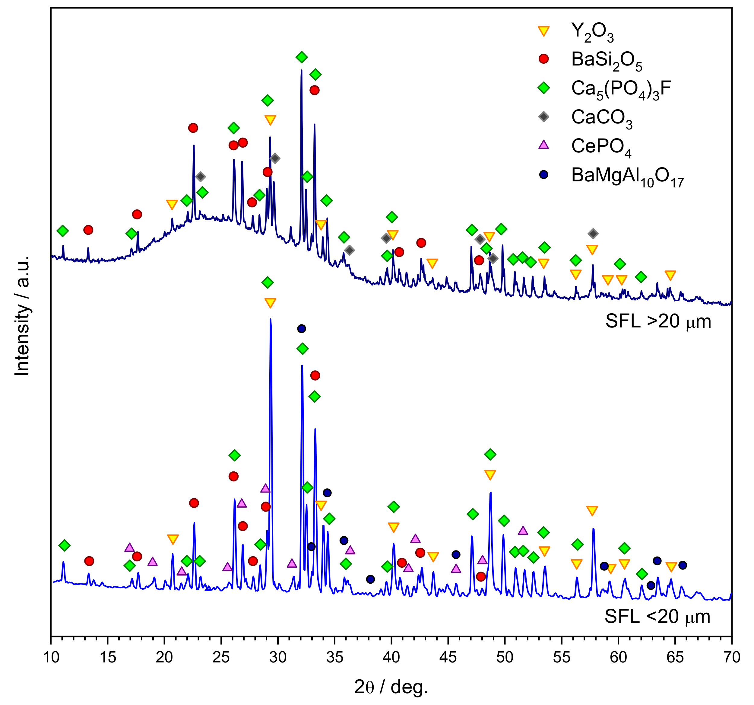
3.1. Mineralogical Analysis of Starting Powders

Figure 1 clearly shows that the two fractions comprised nearly the same main crystal phases, consisting of yttrium oxide (Y2O3, PDF#89-5591), barium silicate (sanbornite, BaSi2O5, PDF#83-1445), and calcium fluoro-phosphate (fluorapatite, Ca5(PO3)4F, PDF#15-08756). The reported compounds are likely just end members of complex solid solutions, comprising REEs, defining the ‘phosphors,’ i.e., substances responsible for the luminescence, when exposed to radiant energy (in turn produced by the electric current-induced excitation of mercury vapour, inside the fluorescence lamps) [22]. All reported compounds are known as ‘hosts’ for rare-earth ions, replacing Y3+, Ba2+, Ca2+, and P5+ ions in the relative crystal lattices [23,24,25]. As an example, the suggested Y2O3 phase is practically not distinguishable from the lanthanum-containing solid solution La0.05Y1.95O3 (ICSD #98-19-3043). Pure fluorapatite, analogously, cannot be distinguished from cerium-containing solid solution Ca4.825Ce0.165F0.74H2Na0.01P2.841Si0.159O12.26 (COD #99-900-0169). The main differences between the two fractions are represented by the presence of calcite (CaCO3, PDF#72-1652), known as the minor (luminescent) phase within the phosphors for fluorescent lamps [26] and a substantial amount of glass in the coarse fraction. The remarkable glass content, for the coarse fraction of SFL, may be inferred from the wide ‘amorphous halo’ in the 2θ = 16–37° interval; the flatness of the background of the diffraction pattern, for the fine fraction of SFL, suggests a very limited content of amorphous phase.
The different content of glass is the likely reason for the remarkable difference in overall chemical composition between the two fractions, reported in Table 1. We cannot exclude, however, the different proportions in the crystalline compounds, as well as the presence of some compounds only in one fraction. As an example, minor amounts of monazite (cerium phosphate, CePO4, COD#99-900-0171) and Ba-/Mg aluminate (BaMgAl10O17, COD#99-900-0001) could be detected only for the finest fraction.

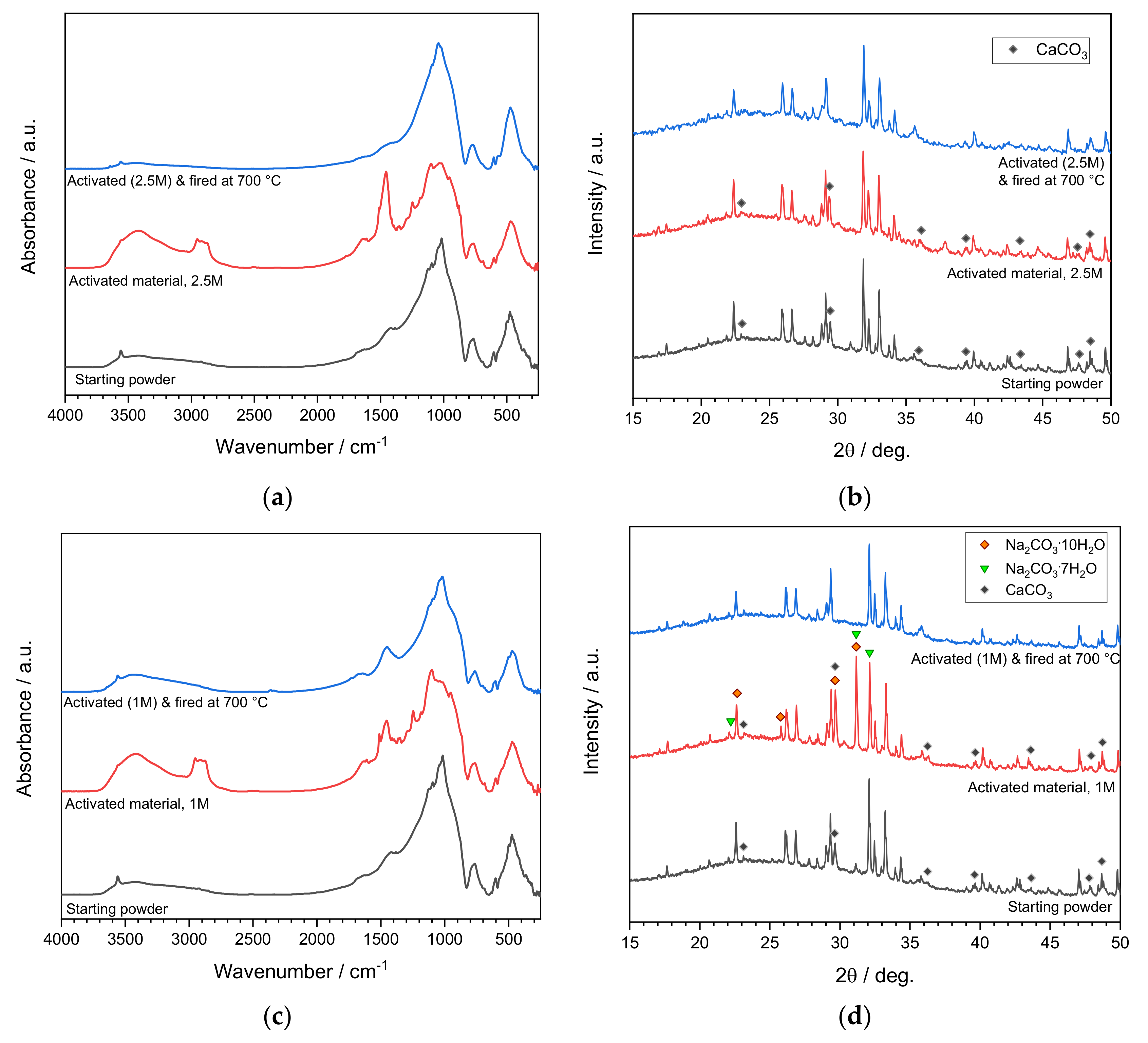
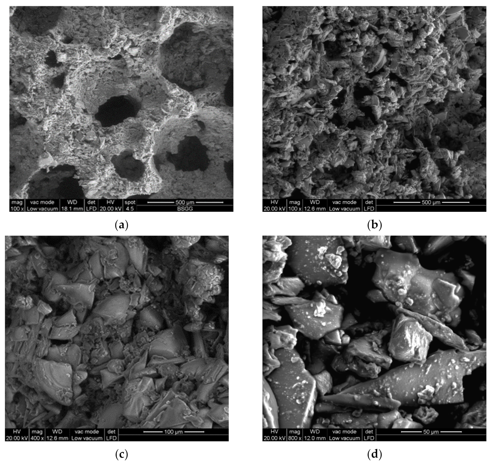
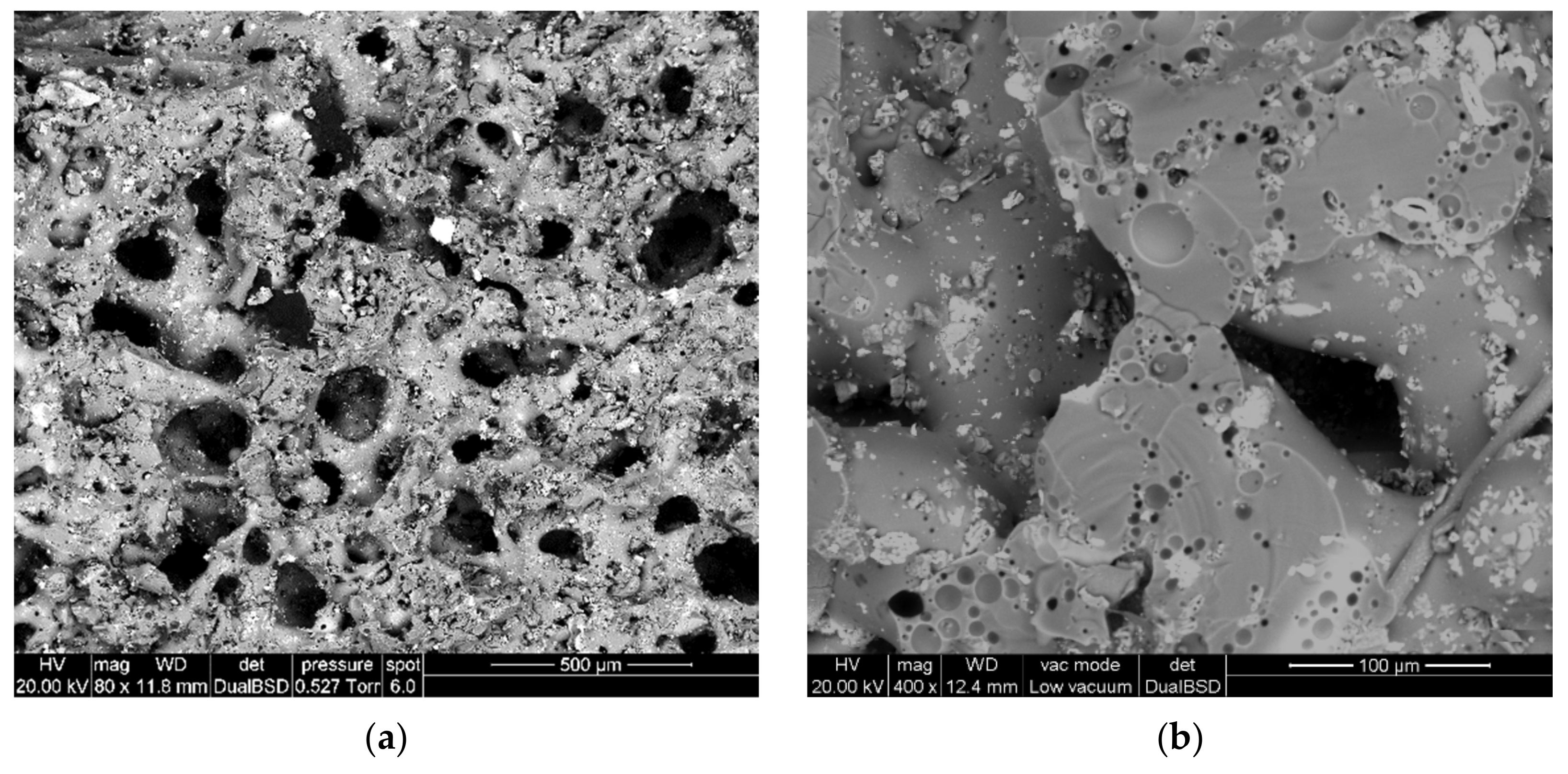
3.2. Activation of Coarse Powders (SFL > 20 μm)

The first series of experiments concerned the activation of an aqueous suspension of coarse SFL powders with NaOH, used in the same molarity (2.5M) adopted with the first experiments on ‘inorganic gel casting’ of soda-lime glass [2]. This approach had been successfully extended to a number of waste-derived glasses for manufacturing highly porous foams already at room temperature by frothing [17,18]. Figure 2a illustrates the typical structure obtained from ‘inorganic gel casting’ applied to a waste-derived glass (glass from the plasma processing of municipal solid waste) [27]: a system of interconnected pores is determined after the consolidation of glass particles around gas bubbles. Figure 2b clearly testifies that when operating with coarse SFL, on the contrary, a similar foamed structure could not be developed. The poor control of the microstructure in the green state could be ascribed to the particular morphology of SFL powders, consisting of edgy platelets, which probably complicated the mutual sliding. Anyway, the gelation, with simultaneous freezing of interstitial porosity, is evident from Figure 2c, showing particles ‘glued’ by a thin surface layer. The reduction of NaOH molarity (1 M), again, did not determine any foaming; as shown by Figure 2d, however, the binding of adjacent particles was confirmed.
The setting of suspensions was studied by means of infrared spectroscopy (in absorbance mode) and mineralogical analysis, as illustrated by Figure 3a,b. From FTIR analysis (Figure 3a), it can be clearly noted that the material before activation and after firing at 700 °C had nearly identical spectra, whereas the activated state was distinguishable for a much larger band in the 3000–3500 cm−1 and for a quite neat absorption peak centred at approximately 1450 cm−1. Such signals are consistent, according to the identification of bands performed by García Lodeiro et al. [28], with the formation of a hydrated calcium silicate (C-S-H) gel and carbonate compounds, respectively.
Calcium carbonate (calcite) was already present in the as-received state (see Figure 1 and bottom pattern of Figure 3b). This specific phase was the only to disappear, undergoing decomposition, upon firing at 700 °C (see the top pattern in Figure 3b); the rest of the crystal phases (Y2O3, fluorapatite, sanbornite) remained unchanged. The activation did not lead to any transformation of calcite, considering the unaltered height of the relative diffraction maxima. The sharp peak at 1450 cm−1, in the FTIR spectrum, was thus attributed to the contribution of an extra carbonated phase. A possible explanation could be represented by the formation of amorphous calcium carbonate mixed with amorphous C-S-H gel or amorphous C-S-H gel with some structural modifications [29]. The bands, centred at 2900 cm−1 and visible only in the hardened glass suspension, were attributed to C–H vibrations of the organic surfactant [30].
The change in the activating solution (from 2.5 M to 1 M NaOH) had some consequences on the nature of the compounds responsible for the same setting, as illustrated by Figure 3c,d. In the FTIR pattern of hardened glass suspension (Figure 3c), the large band in the 3000–3500 cm−1 was visible again, while the absorption peak at approximately 1450 cm−1 was much reduced. Interestingly, according to the mineralogical analysis (Figure 3d), the activated material exhibited a well-distinguishable diffraction peak (2θ ≈ 31°) and an enhanced peak in the position (2θ ≈ 29.5°) corresponding to the main diffraction line of calcite. A clear identification of newly formed phases was not possible, but hydrated sodium carbonate phases (Na2CO3·7H2O, PDF#15-0800, and Na2CO3·7H2O, PDF#25-0816) are known to present major diffraction lines consistent with the new positions or overlapping with those of the phosphor phases (see symbols in Figure 3d). As in the case of 2.5 M activation, carbonate phases (already present in the starting material or newly formed) disappeared after firing at 700 °C.
The thermal treatment transformed masses of weakly bonded SFL powders into highly porous foams, as shown by Figure 4. Softened glass particles underwent mutual joining, while an abundant porosity remained from air trapped upon gelation of suspensions. No foaming could be ascribed to gas released from the decomposition of surfactant, known to occur below 400 °C [2]. Some gas release could be due, on the contrary, to the decomposition of hydrated and carbonate compounds and also motivate the clusters of closed micropores visible in Figure 4b. The same Figure 4b illustrates the inclusion of phosphor particles (visible from the light colour, in backscattered electron images, in turn, associated with heavy elements) within a glass matrix.
As reported by Table 2, the total porosity of samples from SFL powders was between 78–80 vol%; the porosity was mainly open, as in previous studies on foams manufactured with the support of alkali activation [2,17,18]. Interestingly, the high porosity did not compromise the compressive strength, exceeding 4 MPa. Combined with the density, it corresponded to a specific strength ranging from 7.9 to 10.3 MPa·cm3/g, comparing well with that (10 MPa·cm3/g) of commercial, close-celled glass foams (‘Foamglas’), known to feature some contribution to the strength from cell walls [2].
Leaching tests were performed to evaluate the effective stabilization of heavy metals and REEs. As shown by Table 3, the two foams exhibited a nearly negligible release of REEs. Heavy metals remained well below the thresholds not only for not hazardous materials but also for ‘inert’ materials, according to the European norms (Norm EN 12457-4) [20]. The leachates were also within the limits adopted for recycled materials used specifically in building applications, except for tungsten, reasonably deriving from electrodes of fluorescent lamps [27]. The toxicity of this metal is quite controversial since it is known as a non-toxic alternative to lead in a wide range of industrial and military applications, but the mechanisms by which tungsten affects the human body are still unclear [31]. In the perspective of the actual use of SFL-derived foams, the proposed methodology may still be valid in the hypothesis of pre-treatment of SFL powders specifically aimed at tungsten removal or of the cladding of foams with a sealing glaze, as proposed for commercial glass foams [32].

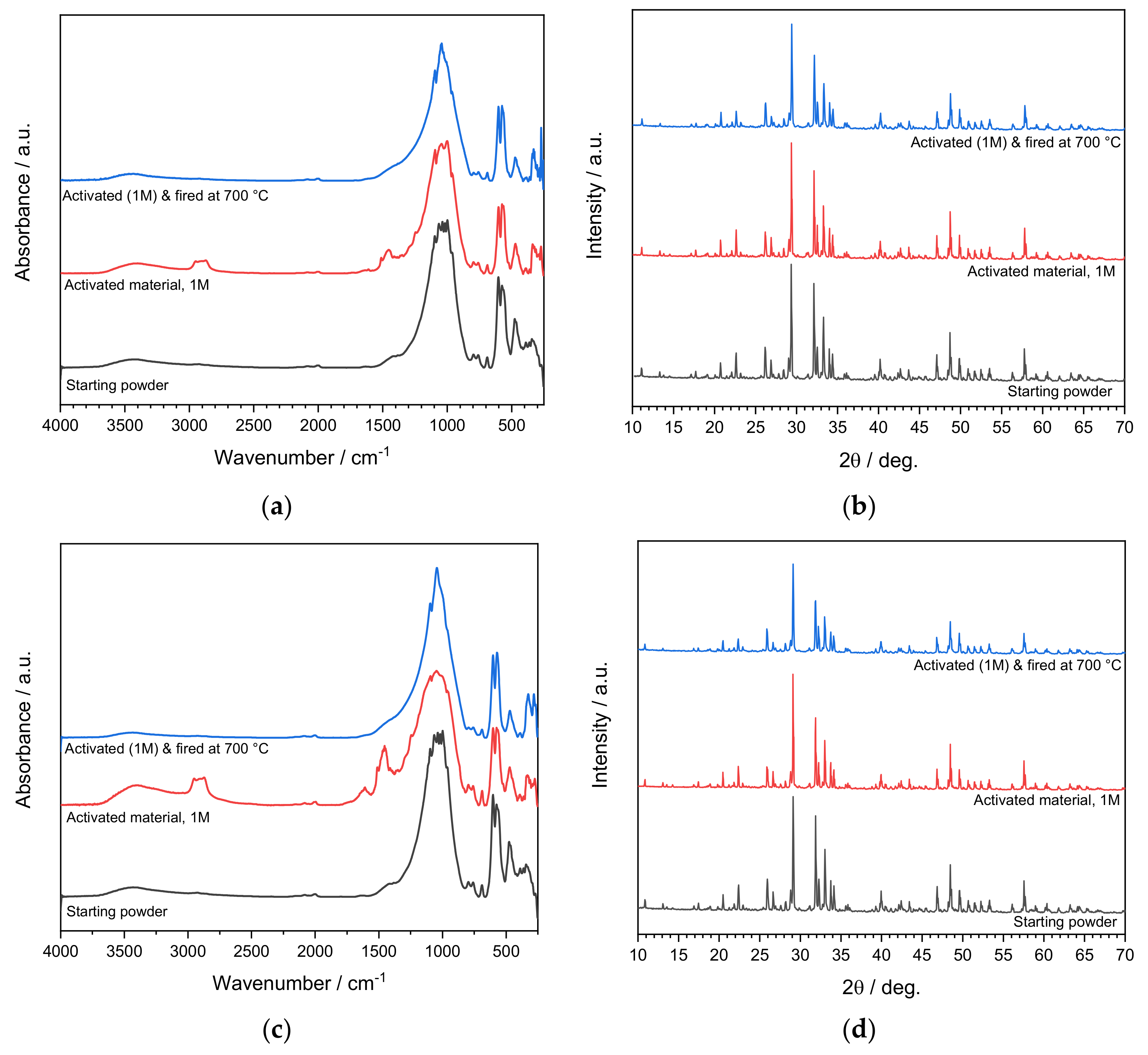
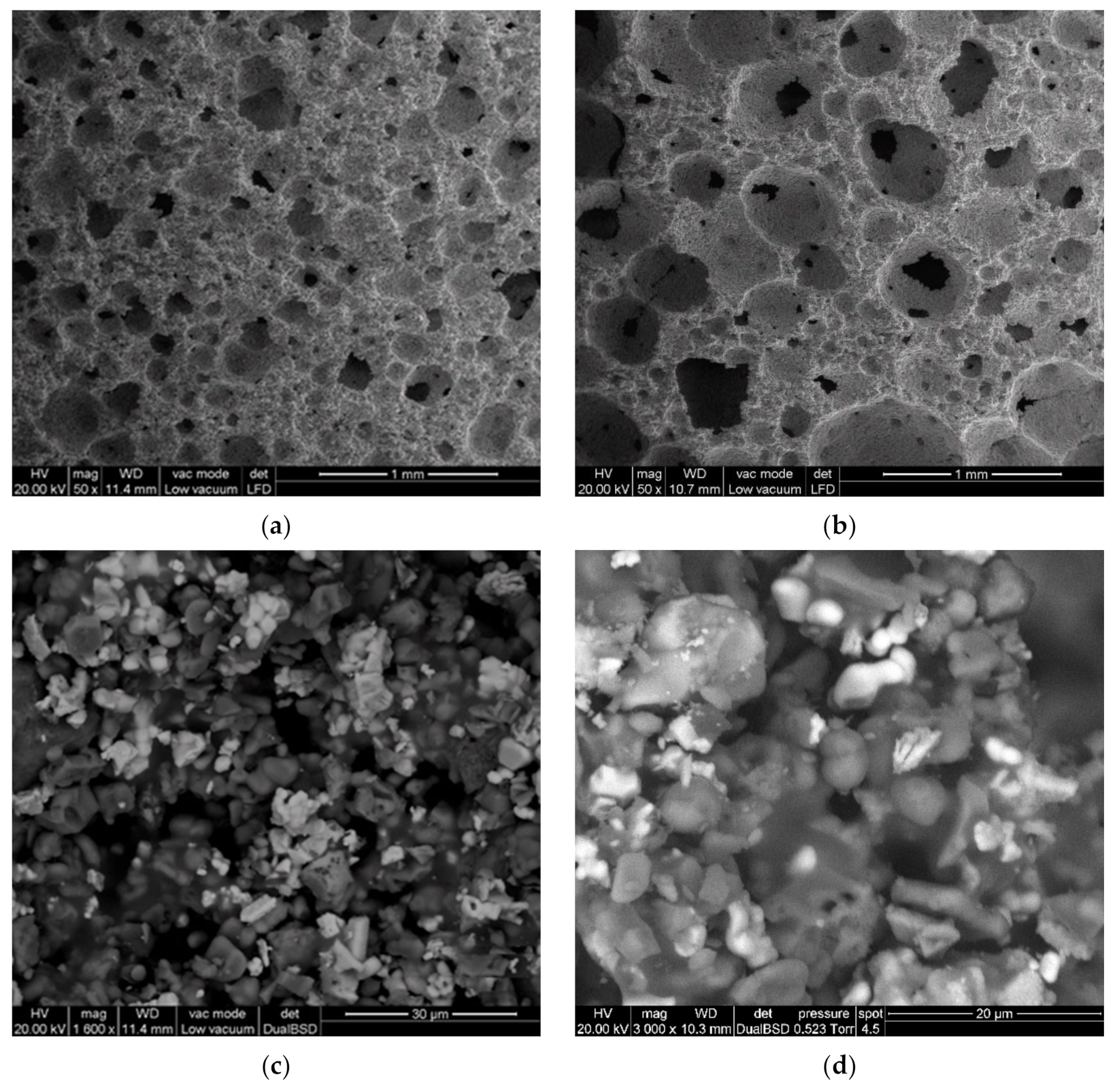
3.3. Activation of Fine Powders (SFL < 20 μm)

The application of the second processing conditions (1 M NaOH) to fine powders, instead of coarse powders, did not allow any setting. The low quantity of glass (inferred from Figure 1) evidently did not suffice for the gelation of suspensions. In an attempt to promote the gelation, the fine fraction of phosphors was added with waste glass deriving from the purification of soda-lime container glass (SLG) cullet. The SFL/SLG weight proportion was kept at 9:1 so that the glass amount remained quite limited. Anyway, the glass addition sufficed in promoting the gelation, in turn, exploited for the development of ‘green’ foams, consisting of a multitude of adjacent pores (each corresponding to the consolidation of the starting suspension around air bubbles, incorporated by intensive mechanical stirring), as illustrated by Figure 5a,b. The ‘gluing’ of particles is evident, in particular, from Figure 5c,d.
As shown by Figure 6a, the FTIR spectrum for the activated mixture differed from starting material and fired material only for the band attributed to C-S-H compounds (3000–3500 cm−1), to the surfactant (2900 cm−1) and to carbonate compounds (1450 cm−1). The signals were quite weak, consistently with the limited amount of SLG; such constraint is the reason for no appreciable changes in the diffraction pattern (Figure 6b).
A reduced solid loading probably promoted the solution/solid interaction. The same bands attributed to C-S-H, surfactant, and carbonates were slightly more intense (Figure 6c), but again, no newly formed compound could be detected from mineralogical analysis (Figure 6d). A possible explanation could be represented by the formation of amorphous calcium carbonate mixed with amorphous C-S-H gel.
The softening of the SLG additive enabled the consolidation of foams upon firing at 700 °C; according to the limited glass content, however, there was no collapse of the cellular structure determined already in the green state, as shown by Figure 7a,b. The effective flow of SLG is evident from Figure 7c,d, showing the inclusion of fine particles in a glass mass. Figure 7d, in particular, is interesting for the light-coloured spots associated (in backscattered electron images) with heavy elements, such rare earth elements: phosphor particles were not simply embedded in the glass but, according to their shaded contours, underwent some interdiffusion with the matrix.
Unlike those from coarse powders, foams from a fine fraction of SFL did not exceed any leaching limit for heavy metal elements (see Table 3). The limited densification of struts (Figure 5c,d) evidently limited the compressive strength of the new foams (not exceeding 2.2 MPa, and corresponding to a strength-to-density ratio not exceeding 2.6 MPa·cm3/g), as reported by Table 2. However, the obtained cellular materials, for the abundant and tortuous porosity (well above 70 vol%), may be interesting when applied as not-load-bearing thermal and acoustic insulators. Both density and compressive strength of foams from fine fraction of SFL actually fall in the typical range of commercial insulators, such as aerated concrete (density from 0.4 to 0.9 g/cm3, compressive strength from 1.2 to 1.9 MPa) [33].

4. Conclusions

Inorganic residues from the dismantling of fluorescent lamps were successfully converted into highly porous glass-based foams, according to a simple methodology, based on gelation in alkaline solutions and viscous flow sintering at moderate temperature (700 °C). The glass-enriched, coarse fraction did not allow the definition of a homogeneous foamed structure by the mechanical stirring of suspensions; a foamed structure, however, was determined by the reshaping of pores upon extensive viscous flow sintering of the glass component. When operating with the glass-poor fine fraction, gelation was enabled by the addition of a limited amount of waste soda-lime glass. In this case, the cellular structure was defined already upon mechanical stirring of suspensions. Except for tungsten, the process allowed the stabilization of heavy metals and rare-earth ions for foams from coarse residues.

Author Contributions

Conceptualization, E.B., R.B., and P.S.; methodology, D.B., and P.P.; investigation, E.R., A.R.R., D.B., and F.Z.; writing—original draft preparation, E.R., R.B., and P.S.; writing—review and editing, E.B.; supervision, E.B., R.B., and P.S.; funding acquisition, E.B. All authors have read and agreed to the published version of the manuscript.

Funding

Enrico Bernardo acknowledges the additional funding from the University of Padova (Department of Industrial Engineering) in the framework of the “SusPIRe” (Sustainable porous ceramics from inorganic residues, BIRD202134).

Institutional Review Board Statement

Not applicable.

Informed Consent Statement

Not applicable.

Acknowledgments

The authors thank Spherae S.r.l. (Gorizia, Italy) for the supply of the SFL powders and SASIL S.p.a. (Brusnengo, Biella, Italy) for the supply of soda-lime glass.

Conflicts of Interest

The authors declare no conflict of interest. The funders had no role in the design of the study; in the collection, analyses, or interpretation of data; in the writing of the manuscript, or in the decision to publish the results.

References

  1. Ashby, M.F. Materials and the Environment: Eco-Informed Material Choice, 2nd ed.; Buttersworth-Heinemann: Oxford, UK, 2013. [Google Scholar] [CrossRef]
  2. Rincón Romero, A.; Giacomello, G.; Pasetto, M.; Bernardo, E. Novel ‘inorganic gel casting’ process for the manufacturing of glass foams. J. Eur. Ceram. Soc. 2017, 37, 2227–2234. [Google Scholar] [CrossRef]
  3. Bonifazi, G.; Serranti, S. Imaging spectroscopy based strategies for ceramic glass contaminants removal in glass recycling. Waste Manag. 2006, 26, 627–639. [Google Scholar] [CrossRef] [PubMed]
  4. Farcomeni, A.; Serranti, S.; Bonifazi, G. Non-parametric analysis of infrared spectra for recognition of glass and glass ceramic fragments in recycling plants. Waste Manag. 2008, 28, 557–564. [Google Scholar] [CrossRef] [PubMed]
  5. Rincón Romero, A.; Marangoni, M.; Cetin, S.; Bernardo, E. Recycling of inorganic waste in monolithic and cellular glass-based materials for structural and functional applications. J. Chem. Technol. Biotechnol. 2016, 91, 1946–1961. [Google Scholar] [CrossRef] [Green Version]
  6. Petersen, R.R.; König, J.; Yue, Y. The viscosity window of the silicate glass foam production. J. Non-Cryst. Solids 2017, 456, 49–54. [Google Scholar] [CrossRef]
  7. Chinnam, R.K.; Francis, A.A.; Will, J.; Bernardo, E.; Boccaccini, A.R. Review. Functional glasses and glass-ceramics derived from iron rich waste and combination of industrial residues. J. Non-Cryst. Solids 2013, 365, 63–74. [Google Scholar] [CrossRef]
  8. Rey-Raap, N.; Gallardo, A. Removal of mercury bonded in residual glass from spent fluorescent lamps. J. Environ. Manag. 2013, 115, 175–178. [Google Scholar] [CrossRef] [PubMed] [Green Version]
  9. Belardi, G.; Ippolito, N.; Piga, L.; Serracino, M. Investigation on the status of rare earth elements contained in the powder of spent fluorescent lamps. Thermochim. Acta 2014, 591, 22–30. [Google Scholar] [CrossRef]
  10. Krishnamurthy, N.; Gupta, C.K. Extractive Metallurgy of Rare Earths, 2nd ed.; CRC Press: Boca Raton, FL, USA, 2016. [Google Scholar] [CrossRef]
  11. Song, X.; Chang, M.H.; Pecht, M. Rare-Earth elements in lighting and optical applications and their recycling. JOM 2013, 65, 1276–1282. [Google Scholar] [CrossRef]
  12. Deshmane, V.G.; Islam, S.Z.; Bhave, R.R. Selective recovery of rare earth elements from a wide range of e-waste and process scalability of membrane solvent extraction. Environ. Sci. Technol. 2020, 54, 550–558. [Google Scholar] [CrossRef]
  13. Klinger, J.M. Rare earth elements: Development, sustainability and policy issues. Extr. Ind. Soc. 2018, 5, 1–7. [Google Scholar] [CrossRef]
  14. Lukowiak, A.; Zur, L.; Tomala, R.; LamTran, T.N.; Bouajaj, A.; Strek, W.; Righini, G.C.; Wickleder, M.; Ferrari, M. Rare earth elements and urban mines: Critical strategies for sustainable development. Ceram. Int. 2020, 16, 26247–26250. [Google Scholar] [CrossRef]
  15. Innocenzi, V. Treatment of spent fluorescent lamps, cathode-ray tubes, and spent catalysts by hydrometallurgical procedures. In Waste Electrical and Electronic Equipment Recycling: Aqueous Recovery Methods; Vegliò, F., Birloaga, I., Eds.; Woodhead Publishing: Sawston, UK, 2018; pp. 139–160. [Google Scholar] [CrossRef]
  16. Yurramendi, L.; Gijsemans, L.; Forte, F.; Aldana, J.L.; del Río, C.; Binnemans, K. Enhancing rare-earth recovery from lamp phosphor waste. Hydrometallurgy 2019, 187, 38–44. [Google Scholar] [CrossRef]
  17. Ramteke, D.D.; Hujova, M.; Kraxner, J.; Galusek, D.; Rincón Romero, A.; Falcone, R.; Bernardo, E. Up-cycling of ‘unrecyclable’ glasses in glass-based foams by weak alkali-activation, gel casting and low-temperature sintering. J. Clean. Prod. 2021, 278, 123985. [Google Scholar] [CrossRef]
  18. Rincón Romero, A.; Salvo, M.; Bernardo, E. Up-cycling of vitrified bottom ash from MSWI into glass-ceramic foams by means of ‘inorganic gel casting’ and sinter-crystallization. Constr. Build. Mater. 2018, 192, 133–140. [Google Scholar] [CrossRef]
  19. Vaitkus, A.; Merkys, A.; Gražulis, S. Validation of the Crystallography Open Database using the Crystallographic Information Framework. J. Appl. Crystallogr. 2021, 54, 661–672. [Google Scholar] [CrossRef]
  20. Standard UNI EN 12457-2:2002. Characterisation of Waste—Leaching—Compliance Test for Leaching of Granular Waste Materials and Sludges—Part 2: One Stage Batch Test at a Liquid to Solid Ratio of 10 L/kg for Materials with Particle Size Below 4 mm (Without or With Size Reduction). Available online: https://standards.iteh.ai/catalog/standards/cen/db6fbdf3-1de7-457c-a506-46c4898e3f09/en-12457-2-2002 (accessed on 29 June 2021).
  21. Badocco, D.; Lavagnini, I.; Mondin, A.; Tapparo, A.; Pastore, P. Limit of detection in the presence of instrumental and non-instrumental errors: Study of the possible sources of error and application to the analysis of 41 elements at trace levels by induced coupled plasma-mass spectrometry technique. Spectroc. Acta Part B Atom. Spectr. 2015, 107, 178–184. [Google Scholar] [CrossRef]
  22. Ronda, C. Rare-Earth Phosphors: Fundamentals and Applications. Reference Module in Materials Science and Materials Engineering; Elsevier: Amsterdam, The Netherlands, 2017. [Google Scholar] [CrossRef]
  23. Jayaramaiah, J.R.; Lakshminarasappa, B.N.; Nagabhushana, B.M. Luminescence studies of europium doped yttrium oxide nano phosphor. Sens. Actuator B Chem. 2012, 173, 234–238. [Google Scholar] [CrossRef]
  24. Alajlani, Y.; Can, N. Novel Dy and Sm activated BaSi2O5 phosphors: Insights into the structure, intrinsic and extrinsic luminescence, and influence of doping concentration. J. Lumines. 2021, 230, 117718. [Google Scholar] [CrossRef]
  25. Owens, C.L.; Nash, G.R.; Hadler, K.; Fitzpatrick, R.S.; Anderson, C.G.; Wall, F. Apatite enrichment by rare earth elements: A review of the effects of surface properties. Adv. Colloid Interface Sci. 2019, 265, 14–28. [Google Scholar] [CrossRef]
  26. Raposo, C.; Carvalhinho Windmöller, C.; Alves Durão Júnior, W. Mercury speciation in fluorescent lamps by thermal release analysis. Waste Manag. 2003, 23, 879–886. [Google Scholar] [CrossRef]
  27. Rabelo Monich, P.; Rincón Romero, A.; Höllen, D.; Bernardo, E. Porous glass-ceramics from alkali activation and sinter-crystallization of mixtures of waste glass and residues from plasma processing of municipal solid waste. J. Clean Prod. 2018, 188, 871–878. [Google Scholar] [CrossRef]
  28. García Lodeiro, I.; Macphee, D.E.; Palomo, A.; Fernández-Jiménez, A. Effect of alkalis on fresh C–S–H gels. FTIR analysis. Cem. Concr. Res. 2009, 39, 147–153. [Google Scholar] [CrossRef]
  29. Black, L.; Breen, C.; Yarwood, J.; Garbev, K.; Stemmermann, P.; Gasharova, B. Structural features of C–S–H(I) and its carbonation in air—a Raman spectroscopic study. Part II: Carbonated phases. J. Am. Ceram. Soc. 2007, 90, 908–917. [Google Scholar] [CrossRef]
  30. Elsayed, H.; Rincón Romero, A.; Ferroni, L.; Gardin, C.; Zavan, B.; Bernardo, E. Bioactive Glass-Ceramic Scaffolds from Novel ‘Inorganic Gel Casting’ and Sinter-Crystallization. Materials 2017, 10, 171. [Google Scholar] [CrossRef]
  31. Datta, S.; Vero, S.E.; Hettiarachchi, G.M.; Johannesson, K. Tungsten contamination of soils and sediments: Current state of science. Curr. Pollut. Rep. 2017, 3, 55–64. [Google Scholar] [CrossRef]
  32. Ventrella, A.; Smeacetto, F.; Salvo, M.; Ferraris, M. A New glass coating for foam glass. Int. J. Appl. Ceram. Technol. 2011, 8, 187–193. [Google Scholar] [CrossRef]
  33. Ansys Granta EduPack. 2021. Available online: https://www.grantadesign.com/ (accessed on 29 June 2021).
Figure 1. Mineralogical analysis of SFL fractions.
Applsci 11 06056 g001
Figure 2. (a) An example of ‘green’ foam from frothing of an alkali-activated suspension of waste-derived glass; (b) a porous structure from frothing the suspension of coarse SFL powders in 2.5 M NaOH aqueous solution; (c) SFL powders bound by gel from activation with 2.5 M NaOH aqueous solution; (d) SFL powders bound by gel from activation with 1 M NaOH aqueous solution.
Applsci 11 06056 g002
Figure 3. The evolution of samples from coarse SFL powder activated in 2.5 M NaOH solution (a,b) and 1 M NaOH solution (c,d).
Applsci 11 06056 g003
Figure 4. An example of glass foam from coarse SFL powder after firing at 700 °C (GF-1 sample, 2.5 M NaOH): (a) the overall cellular structure; (b) the details of micropores.
Applsci 11 06056 g004
Figure 5. Microstructural details of ’green’ foams from fien SFL powder/SLG mixture after activation at low temperature: (a,b) overall cellular structure; (c,d) binding of adjacent particles.
Applsci 11 06056 g005
Figure 6. The evolution of samples from fine SFL powder/SLG mixture after activation, low-temperature foaming and drying, prepared according to different solid content: (a) and (b) 68%; (c) and (d) 66%.
Applsci 11 06056 g006
Figure 7. Microstructural details of foams from fine SFL powder/SLG mixture after firing at 700 °C: (a,c) solid content of 68%; (b,d) solid content of 66%.
Applsci 11 06056 g007
Table 1. The chemical composition (wt.%) of the samples used in the study in comparison with that of soda-lime glass (SLG) [2].
OxideSFL > 20 μmSFL < 20 μmSLG [2]
Na2O15.213
MgO2.62.1
Al2O34.08.92.4
SiO257.311.170.8
P2O53.520.0
K2O1.10.21.1
CaO9.734.79.4
BaO2.16.40.2
Eu2O30.31.1
Fe2O31.81.00.3
Y2O32.410.8
Cl2O0.1
La2O31.8
Ce2O32.0
MnO0.8
Tb2O30.9
ZnO0.10.1
B2O30.1
Table 2. Experimental conditions and mechanical properties of the sintered samples.
SampleMolarity
NaOH
(M)
S/L
(%)
SLG
(wt.%)
Density
(g/cm3)
Porosity
(%)
Compressive Strength
(MPa)
GF-12.568ρgeom: 0.57 ± 0.02
ρapp: 2.57 ± 0.07
ρt: 2.63 ± 0.01
Total: 78.4
Open: 77.9
Closed: 0.5
5.8 ± 0.6
GF-21.068ρgeom: 0.53 ± 0.01
ρapp: 2.58 ± 0.05
ρt: 2.61 ± 0.01
Total: 79.9
Open: 79.7
Closed: 0.2
4.2 ± 0.5
GF-31.06810ρgeom: 0.85 ± 0.01
ρapp: 3.26 ± 0.01
ρt: 3.27 ± 0.01
Total: 74.0
Open: 73.9
Closed: 0.1
2.2 ± 0.2
GF-41.06610ρgeom: 0.60 ± 0.01
ρapp: 3.12 ± 0.01
ρt: 3.22 ± 0.01
Total: 81.5
Open: 80.9
Closed: 0.6
1.0 ± 0.1
Table 3. The results of the leaching tests on the developed foams.
ElementGF-1GF-2GF-3GF-4Limit Values (mg/kg)
RecycledInertNon-Hazardous
Ba8.55.52.81.3<20<2020–100
Cr0.110.270.050.08<0.3<0.50.5–10
Mo0.060.060.050.08<0.5<0.50.5–10
V0.0020.010.020.04<1<0.50.5–10
Cu0.00199<0.00131<0.001310.00141<1<22–50
Ni<6.6 × 10⁻⁴<6.6 × 10⁻⁴<6.6 × 10⁻⁴<6.6 × 10⁻⁴<0.4<0.40.4–10
Co<0.3 × 10⁻⁴<0.3 × 10⁻⁴<0.3 × 10⁻⁴<0.3 × 10⁻⁴<1
W3.418.750.941.38<1.5
Hg0.0040.0100.0010.002<0.04<0.010.01–0.2
Cd<0.3 × 10⁻⁴<0.3 × 10⁻⁴<0.3 × 10⁻⁴<0.4 × 10⁻⁴<0.04<0.040.04–0.1
Y<1.1 × 10−42.7 × 10−43.3 × 10−43.9 × 10−4 <0.01
Eu9.4 × 10−46.0 × 10−43.2 × 10−41.8 × 10⁻⁴ <0.01
La1.0 × 10−40.6 × 10−41.5 × 10−41.2 × 10⁻⁴ <0.01
Nb0.5 × 10−41.2 × 10−40.1 × 10−40.2 × 10⁻⁴ <0.01
Gd0.4 × 10−40.3 × 10−40.8 × 10−41.1 × 10⁻⁴ <0.01
Sm0.3 × 10−40.2 × 10−40.1 × 10−40.1 × 10⁻⁴ <0.01
Ce<0.1 × 10⁻⁴<0.1 × 10−40.7 × 10−41.2 × 10⁻⁴ <0.01
U<0.1 × 10⁻⁴<0.1 × 10−40.1 × 10−40.1 × 10⁻⁴ <0.01
Tb<0.2 × 10⁻⁴<0.2 × 10−40.2 × 10−40.4 × 10⁻⁴ <0.01
Cl-28.610.420.218.080080015,000
F-1.422.23.70.58 10150
SO42-9.65.712.18.42500150020,000
pH12.6812.1811.818.55
Conduct. (μS/cm)876482274395
Publisher’s Note: MDPI stays neutral with regard to jurisdictional claims in published maps and institutional affiliations.

