
Power-Flow and Mechanical Efficiency Computation in Two-Degrees-of-Freedom Planetary Gear Units: New Compact Formulas


Abstract
:1. Introduction
...our analysis is based upon an important principle relating to torques and the power lost in friction; this is the fact that magnitudes of the torques acting upon the various members of the gear are quite independent of the motion of the observer who measures them. In addition, the power lost, being determined solely by the internal torques and the relative motions of the wheels within the gear, is also independent of the observer’s motion.
- -
- Two driving members (i.e., those with positive powers) and one driven member (i.e., the one with negative power);
- -
- Two driven members and one driving member.
2. Power-Flow Ratios in a PGU
- -
- Two driving links (namely x and y, and ) and one driving link (namely z, );
- -
- Two driving links (namely x and y, and ) and one driving link (namely z, ).
3. The Algebraic Sign of Virtual Power Flows
- -
- If , then is also negative.
- -
- If , then must be greater than one.
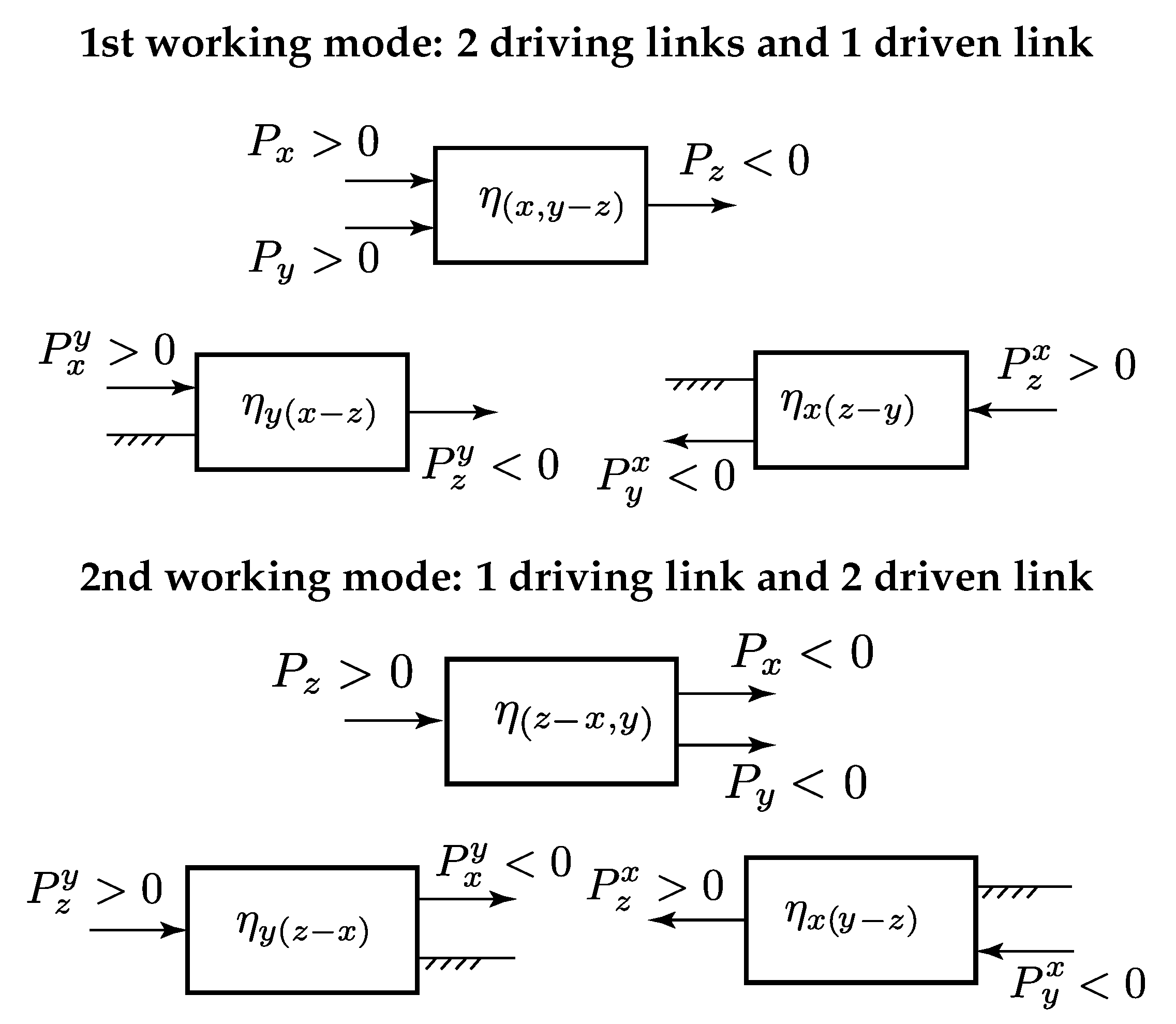
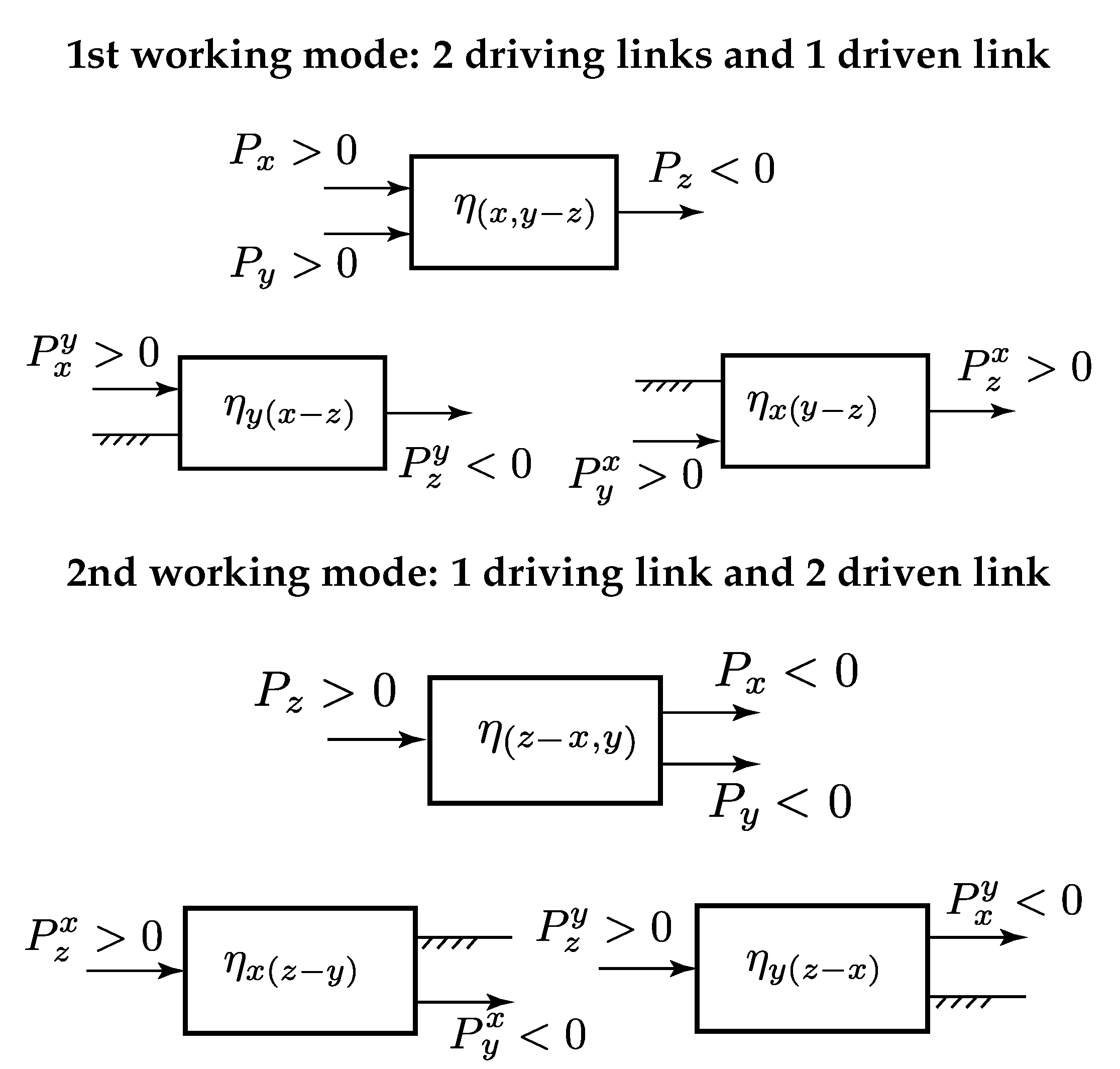
- When and do not have the same algebraic sign, the power ratios and will have simultaneously the same algebraic sign. For all the links, the direction of the virtual power-flow is the same as the actual power flow (see Figure 2).
- When and have the same algebraic sign, power ratios and cannot have simultaneously the same algebraic sign. In particular, the condition is fulfilled when (See Figure 3). Conversely, the condition is fulfilled when .
4. The Modified Radzimovsky Formulas
4.1. Case x and y as Driving Links and z Driven Link
4.2. Case x and y as Driven Links and z Driving Link
5. Numerical Example
6. Conclusions
Author Contributions
Funding
Institutional Review Board Statement
Informed Consent Statement
Data Availability Statement
Conflicts of Interest
Nomenclature
| dof | degree-of-freedom |
| Power of link , greater/less than zero when h is a driving/driven link in the absolute motion; | |
| Potential or virtual power of link x when link y is considered fixed; | |
| PGU | Planetary gear unit; |
| Planet gear ratio (+: internally meshing gears, −: externally meshing gears) | |
| Torque on link x | |
| Absolute angular velocity of link x | |
| Relative angular velocity of link x with respect to link y | |
| Mechanical efficiency of the one dof PGU when link x is fixed and links y and z are driving and driven links, respectively. | |
| Mechanical efficiency of the two dof PGU when operating with links x and y as driving links and z as driven. | |
| Mechanical efficiency of the two dof PGU when operating with links x and y as driven links and z as driving link. |
Appendix A
- and k: subscripts denoting the gears and gear carrier, respectively;
- : planet gear ratio;

| Case | Driving | Driven | Fixed | ||
|---|---|---|---|---|---|
| 1 | i | j | k | ||
| 2 | j | i | k | ||
| 3a | i | k | j | ||
| 3b | i | k | j | ||
| 4a | k | i | j | ||
| 4b | k | i | j | ||
| 5a | j | k | i | ||
| 5b | j | k | i | ||
| 6a | k | j | i | ||
| 6b | k | j | i |
References
- Pennestrì, E.; Mariti, L.; Valentini, P.P.; Mucino, V. Efficiency evaluation of gearboxes for parallel hybrid vehicles: Theory and applications. Mech. Mach. Theory 2012, 49, 157–176. [Google Scholar] [CrossRef]
- Zhang, X.; Mi, C. Vehicle Power Management—Modeling, Control and Optimization; Springer: Berlin/Heidelberg, Germany, 2011. [Google Scholar]
- Chen, C. Power flow analysis of compound epicyclic gear transmission: Simpson gear train. ASME J. Mech. Des. 2011, 133, 5. [Google Scholar] [CrossRef]
- Chen, C. Power flow and efficiency analysis of epicyclic gear transmission with split power. Mech. Mach. Theory 2013, 59, 96–106. [Google Scholar] [CrossRef]
- Esmail, E.L. Meshing efficiency analysis of two degree-of-freedom epicyclic gear trains. ASME J. Mech. Des. 2013, 138, 083301. [Google Scholar] [CrossRef]
- Jianying, L.; Qingchun, H. Power Analysis and Efficiency Calculation of the Complex and Closed Planetary Gears Transmission. Mech. Mach. Theory 2016, 100, 423–433. [Google Scholar] [CrossRef] [Green Version]
- Mohammadpour, M.; Theodossiades, S.; Rahnejat, H. Dynamics and efficiency of planetary gear sets for hybrid powertrains. Proc. IMechE Part C J. Mech. Sci. 2016, 230, 1359–1368. [Google Scholar] [CrossRef] [Green Version]
- Coaccioli, P. Pennestrì. Graph-Based Algorithm for the Evaluation of the Mechanical Efficiency of Epicyclic Gear Drive in Hybrid Scooters. In Graph-Based Modelling in Engineering. Mechanisms and Machine Science; Zawiślak, S., Rysiński, J., Eds.; Springer International Publishing: Berlin/Heidelberg, Germany, 2017; Volume 42, pp. 97–105. [Google Scholar]
- Yang, F.; Feng, J.; Zhang, H. Power flow and efficiency analysis of multi-flow planetary gear trains. Mech. Mach. Theory 2015, 92, 86–99. [Google Scholar] [CrossRef]
- Essam, E.L.; Juber, A.H.; Hussen, H.A. Power flow and efficiency analysis of multi-path transmission with planetary gear train. Int. J. Mech. Eng. Technol. 2018, 9, 412–423. [Google Scholar]
- Hussen, H.A.; Esmail, E.L.; Hussen, R.A. Power Flow Simulation for Two-Degree-of-Freedom Planetary Gear Transmissions with Experimental Validation. Model. Simul. Eng. 2020, 2020, 14. [Google Scholar] [CrossRef]
- De Carlo, M.; Mantriota, G. Electric vehicles with two motors combined via planetary gear train. Mech. Mach. Theory 2020, 148, 103789. [Google Scholar] [CrossRef]
- Ding, H.; Cai, C.; Chen, Z.; Ke, T.; Mao, B. Configuration Synthesis and Performance Analysis of 9-Speed Automatic Transmissions. Chin. J. Mech. Eng. 2020, 33, 21. [Google Scholar] [CrossRef]
- Mantriota, G.; Reina, G. Efficient Power-Split Powertrain for Full Electric Vehicles. In Mechanisms and Machine Science; Springer International Publishing: Berlin/Heidelberg, Germany, 2020; pp. 560–567. [Google Scholar] [CrossRef]
- Pennestrì, E.; Valentini, P.P. A review of formulas for the mechanical efficiency analysis of two degrees-of-freedom epicyclic gear trains. ASME J. Mech. Des. 2003, 125, 602–608. [Google Scholar] [CrossRef]
- Macmillan, R.H. Epicyclic gear efficiencies. Engineer 1949, 23, 727–728. [Google Scholar]
- Chen, C.; Angeles, J. Virtual-power flow and mechanical gear-mesh power losses of epicyclic gear trains. J. Mech. Des. Trans. ASME 2007, 129, 107–113. [Google Scholar] [CrossRef]
- Rotella, D.; Cammalleri, M. Power losses in power-split CVTs: A fast black-box approximate method. Mech. Mach. Theory 2018, 128, 528–543. [Google Scholar] [CrossRef]
- Esmail, E.L. Influence of the Operating Conditions of Two-Degree-of-Freedom Planetary Gear Trains on Tooth Friction Losses. ASME J. Mech. Des. 2018, 140, 054501. [Google Scholar] [CrossRef]
- Malashchenko, V.; Strilets, O.; Strilets, V.; Kłlysz, S. Investigation of the energy effectiveness of multistage differential gears when the speed is changed by the carrier. Diagnostyka 2019, 20, 57–64. [Google Scholar] [CrossRef]
- Cammalleri, M.; Castellano, A. Analysis of hybrid vehicle transmissions with any number of modes and planetary gearing: Kinematics, power flows, mechanical power losses. Mech. Mach. Theory 2021, 162, 104350. [Google Scholar] [CrossRef]
- Sun, Z.; Gao, B.; Sanada, K. Power Loss Evaluation of Automated Manual Transmission with Gearshift Assistant Mechanism. Int. J. Automot. Technol. 2021, 22, 441–454. [Google Scholar] [CrossRef]
- Chen, C.; Liang, T. Theoretic study of efficiency of two-DOFs of epicyclic gear transmission via virtual power. ASME J. Mech. Des. 2011, 133, 031007-1–031007-7. [Google Scholar] [CrossRef]
- Chen, C. Power analysis of epicyclic transmissions based on constraints. ASME J. Mech. Robot. 2012, 4, 041004-1–041004-11. [Google Scholar] [CrossRef]
- Radzimovsky, E.I. A Simplified Approach for Determing Power Losses and Efficiency of Planetary Gear Drives. Mach. Des. 1956, 28, 101–110. [Google Scholar]
- Radzimovsky, E.I. How to find efficiency, speed and power losses in planetary gear drives. Mach. Des. 1959, 31, 144–153. [Google Scholar]
- Pennestrì, E.; Freudenstein, F. The Mechanical Efficiency of Epicyclic Gear Trains. ASME J. Mech. Des. 1993, 115, 645–651. [Google Scholar] [CrossRef]
- Esmail, E.L.; Pennestrì, E.; Hussein Juber, A. Power Losses in Two-Degrees-of-Freedom Planetary Gear Trains: A Critical Analysis of Radzimovsky’s Formulas. Mech. Mach. Theory 2018, 128, 191–204. [Google Scholar] [CrossRef]
- Pennestrì, E.; Freudenstein, F. A Systematic Approach to Power-Flow and Static Force Analysis in Epicyclic Spur-Gear Trains. ASME J. Mech. Des. 1993, 115, 639–644. [Google Scholar] [CrossRef]
- Rabindran, D.; Tesar, D. Parametric design and power-flow analysis of parallel force/velocity actuators. ASME J. Mech. Robot. 2009, 1, 1–10. [Google Scholar] [CrossRef]


Publisher’s Note: MDPI stays neutral with regard to jurisdictional claims in published maps and institutional affiliations. |
© 2021 by the authors. Licensee MDPI, Basel, Switzerland. This article is an open access article distributed under the terms and conditions of the Creative Commons Attribution (CC BY) license (https://creativecommons.org/licenses/by/4.0/).
Share and Cite
Esmail, E.L.; Pennestrì, E.; Cirelli, M. Power-Flow and Mechanical Efficiency Computation in Two-Degrees-of-Freedom Planetary Gear Units: New Compact Formulas. Appl. Sci. 2021, 11, 5991. https://doi.org/10.3390/app11135991
Esmail EL, Pennestrì E, Cirelli M. Power-Flow and Mechanical Efficiency Computation in Two-Degrees-of-Freedom Planetary Gear Units: New Compact Formulas. Applied Sciences. 2021; 11(13):5991. https://doi.org/10.3390/app11135991
Chicago/Turabian StyleEsmail, Essam Lauibi, Ettore Pennestrì, and Marco Cirelli. 2021. "Power-Flow and Mechanical Efficiency Computation in Two-Degrees-of-Freedom Planetary Gear Units: New Compact Formulas" Applied Sciences 11, no. 13: 5991. https://doi.org/10.3390/app11135991
APA StyleEsmail, E. L., Pennestrì, E., & Cirelli, M. (2021). Power-Flow and Mechanical Efficiency Computation in Two-Degrees-of-Freedom Planetary Gear Units: New Compact Formulas. Applied Sciences, 11(13), 5991. https://doi.org/10.3390/app11135991