1. Introduction
In the last decades, stricter environmental policies undertaken against increasing global warming have encouraged the spreading uptake of hybrid electric vehicles. Besides the earliest and most popular series and parallel hybrid architectures, more and more automotive companies—first and foremost Toyota and General Motors—are developing the power-split hybrid electric powertrain [
1,
2,
3,
4,
5].
The power-split layout combines the benefits of both series and parallel hybrid, resulting in a highly flexible system where the internal combustion engine (ICE) is kinematically decoupled by the wheels due to the operation of the electric unit. Two electric machines act as an active continuously variable unit (CVU), which can provide additional power for vehicle propulsion or gather the ICE power in surplus for battery recharging. In addition, regenerative braking and full electric vehicle (FEV) operation are achievable. The power flows within the powertrain are handled by a power-split unit (PSU) made up of planetary gear sets (PGs) and ordinary gear sets (OGs). Multi-PG PSU enables the minimization of the electric machines’ power size by deploying a multi-mode power-split continuously variable transmission (PS-CVT), where some clutches operations lead to several constructive arrangements to select under the desired driving conditions [
6,
7,
8,
9,
10]. Nevertheless, the more complex the transmission constructive layout is, the trickiest the identification of the occurring power flows is [
11,
12,
13], as well as their management [
14,
15,
16,
17].
When implementing energy management strategies aimed at minimizing the powertrain power losses, the friction losses occurring in the transmission should be also considered. Nonetheless, because of the above-mentioned difficulties in multi-mode PS-CVTs analysis, their calculation is far from trivial [
18,
19,
20,
21]. Thus, mechanical power losses are considered in very simple one-PG transmission [
22,
23] or evaluated by using simplified approaches that avoid the analysis of the transmission power flows [
24,
25] or even more often neglected [
26,
27,
28,
29,
30,
31,
32].
The focus of this paper is to provide the global efficiency map of the multi-mode Chevrolet Volt hybrid electric powertrain by assessing all powertrain losses, not only those occurring in the propulsors but also the transmission mechanical power losses. This can be achieved by applying a unified parametric model [
33,
34,
35,
36] without convoluted or case-specific formulations. All the relationships of the model are ruled by few basic functional parameters which can be swiftly derived from any PS-CVT constructive arrangement, even multi-PG or multi-mode [
34,
36]. These enable the calculation of speed, torque, and power ratios in real conditions, by using a fast black-box method [
35,
36] to assess the PSU mechanical losses and then the actual power that the electric machines should provide to the PSU for given ICE power and required output. The whole procedure applies also to the FEV operation [
36].
This unified parametric model was first applied to the transmission of the Chevrolet Volt in [
34], where an alternative design was proposed but any power losses were neglected. Then, the mechanical losses occurring in the PSU were considered in the Chevrolet Volt dimensionless analysis carried out in [
35]. This article aims to consider also the power losses occurring in the propulsors, by moving from the dimensionless variables to those expressed in physical units of measurement. In addition, the analysis of the Chevrolet Volt in FEV operation is presented for the first time.
The utilization of dimensionless independent and dependent variables expressed as speeds, torques, or powers ratios results in utmost generality, which makes the model suitable for analyzing any PS-CVT. Nonetheless, the loss factors of the propulsors are strictly related to their operating point, therefore the brake specific fuel consumption (BSFC) map of the engine and the efficiency maps of the electric machines have to be introduced. By considering different combinations of input and output speeds and torques, it is possible to investigate the powertrain response in terms of the actual functioning point of the propulsors and related power losses, net power flow provided or gathered by the battery, and powertrain global efficiency. This approach outputs the results in some optimal operating maps collecting all data of interest, which allows the determination of the powertrain optimal functioning points based on the desired goal of the energy management strategy to implement. By way of example, this contribution proposes a simplified control strategy in steady-state driving by taking into consideration four possible state of charges (SOCs) of the battery. However, this approach is the ideal basis for the development of new control and energy management strategies, as it applies to any hybrid electric powertrain without requiring an in-deep knowledge of the behavior of each component of the powertrain, thanks to its generality. Therefore, it offers a neutral environment for engineers with different expertise.
The paper is organized as follows.
Section 2 includes the dimensionless PSU mechanical power losses and the dimensionless speeds and real powers of the electric machines in the Chevrolet Volt powertrain in power-split operation, which were previously calculated in [
35]. Then, the same variables are evaluated in FEV operation by using the procedure presented in [
36]. In
Section 3, the propulsors efficiency maps are introduced and the method for calculating and selecting the optimal operating points is described.
Section 4 provides and discusses the results of the application, while
Section 5 concludes the article by framing the new contribution in a broader context.
2. Dimensionless Parametric Approach for Voltec Analysis
The transmission system of the Chevrolet Volt, the so-called Voltec, is a PS-CVT with two PGs and three clutches which enable the multi-mode functioning. A third PG combined with a chain drive acts as a fixed-ratio OG in the final drive.
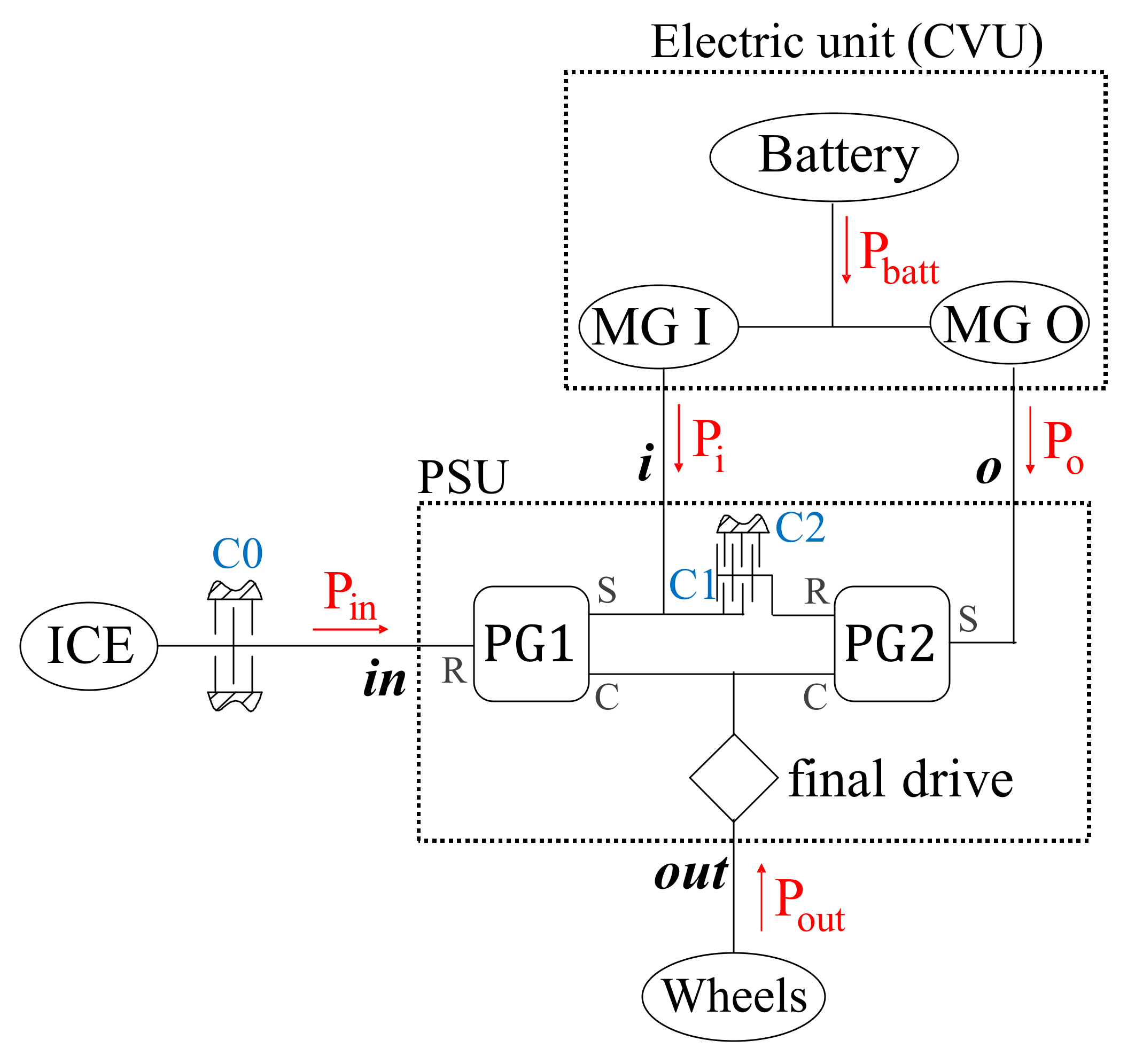
Figure 1 shows the Voltec functional layout derived from [
37] and previously described in [
34,
35]. The PGs and the final drive make up the PSU, which can be considered as a four-port device linked with the ICE (by the shaft
in), the wheels (by the shaft
out), and the electric motor-generator (MG) I (by the shaft
i) and MG O (by the shaft
o). The positive sign of the power flows is indicated by the arrows. The clutches C0, C1, and C2 are exploited to shift between different modes, as reported in
Table 1. By engaging the only C2 clutch, the PG2 ring gear is braked to the frame, thus only PG1 acts as an epicyclic gear unit with non-proportional speeds of its branches. This realizes an input-split mode, mainly exploited for lower vehicle speeds. At higher speeds, a compound-split mode is achieved, by engaging only the clutch C1 which connects the PG2 ring gear to the MG I and the PG1 sun gear. It should be noted that engaging C1 and C2 simultaneously realizes a fixed-ratio parallel mode, where only MG O can be active and the ICE speed is univocally coupled to the vehicle speed. Moreover, by additionally engaging the one-way clutch C0, which locks to the frame the ICE and the PG1 ring gear, two FEV modes can be performed. However, as shown in
Table 1, General Motors considers only the FEV operation derived from the input-split arrangement.
The schematization of any PSU as a four-port device is always valid, regardless of the actual PSU constructive layout. This enables the exploitation of some general relationships between speeds, torques, and powers of the main PSU external ports which can be applied to any PS-CVT [
33,
35,
36]. On the other hand, the PGs and OGs constructive parameters and their arrangement within the PSU lead to the definition of the basic functional parameters which rule the equations of the unified parametric model considered in this article. The constructive parameter here used for the definition of the planetary gear sets is the Willis’ ratio
, defined as the ratio between the rotational speed of the ring gear and the one of the sun gear while the carrier is still. The Willis’ ratios of the two PGs are
and
, the fixed-ratio of the final drive is
. The functional parameters of the Voltec input-split and compound-split modes were identified in [
34]. These are the mechanical points
and
and the corresponding speed ratios
and
, listed in
Table 2. The former are defined as the overall speed ratio
achieved when the
i or
o shaft is motionless, respectively. In general terms, the corresponding speed ratio
is the
j-th speed ratio
achieved when the shaft
k is motionless. The mechanical points often coincide with the overall speed ratio at which a mode shift occurs, since one of the two electric machines can be turned off. Therefore, a parallel hybrid functioning is achieved at the mechanical points.
Once known the parameters of
Table 2, the dimensionless approach addressed in [
35,
36] can be applied to the Voltec to analyze both the power-split and FEV operation in terms of speed, torque, and power ratios, by including the evaluation of the PSU mechanical power losses.
2.1. Dimensionless Speeds, Powers and Mechanical Losses in Voltec Power-Split Operation
The Voltec PS-CVT in power-split operation was previously analyzed in [
34,
35]. To avoid repetition, this section includes only the outcomes of these previous applications, not the procedure implemented to obtain them. The results are shown in
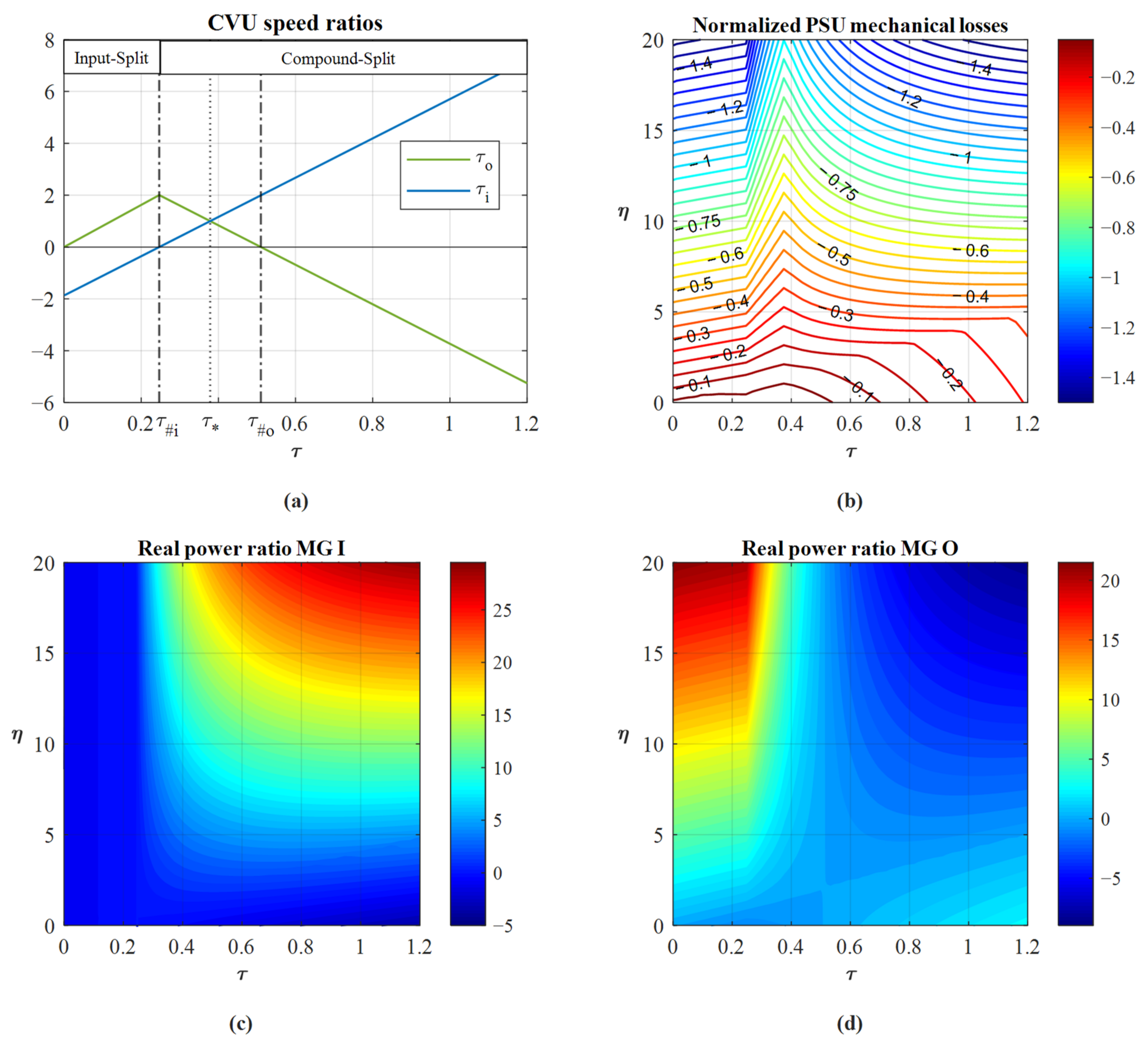
Figure 2. Starting from the functional parameters of
Table 2, the speed ratio
between MG I and the ICE was computed as a function of the overall speed ratio
, as well as the speed ratio
between MG O and the ICE. These are shown in
Figure 2a for both input- and compound-split mode. The shift between one mode to the other occurs at the mechanical point
. For
both electric machines rotate at the same speed, therefore both PGs work at their synchronous condition. At the PGs synchronism, the PSU mechanical power losses (
Figure 2b) show a minimum, because the absence of relative motion between PGs branches eliminates the PGs friction losses. The mechanical power losses of
Figure 2b were calculated as a fraction of the input power as a function of the overall speed ratio
and the opposite of the overall power ratio
. Note that
is not a global efficiency, but a variable exploited to model the possibility of the battery to provide or absorb power. Therefore, it can also be far higher than one, if the demanded output power is mainly provided by the battery rather than the ICE. The PSU losses enabled the calculation of the real power that the electric machines should provide to or collect from the PSU as a fraction of the input power (
Figure 2c,d).
2.2. Dimensionless Speeds, Powers and Mechanical Losses in Voltec Full-Electric Operation
The relationships exploited in [
34,
35] to analyze the power-split operation were rearranged in [
36] to model also the FEV functioning mode. These are exploited in this section to apply the unified parametric model to the Voltec in FEV operation for the first time. Nonetheless, to find the best balance between brevity and self-consistency of the paper, this section presents the only implementation of formulas that were introduced and explained in the previous works [
33,
34,
35,
36], to which we refer the reader for more information. However,
Appendix A outlines the major features of the model to facilitate the understanding of the content of this section.
As the engine is inactive in FEV driving (clutch C0 is engaged), speeds and power can be more conveniently normalized to the output ones. Since the shaft
in is motionless, the speed ratio between every electric machine and the shaft
out is univocally defined as:
The functional parameters used in Equation (1) are those related to the input-split mode, since it is the only mode exploited by General Motors to perform the FEV operation.
The dimensionless PSU power losses can be computed by the fast black-box method proposed in [
35] adapted to the FEV analysis, as described in [
36] and summarized in
Appendix A. The considered efficiencies of the final drive (
) and of the PGs in fixed-carrier functioning (
) are the same as those assumed in [
35]. The total mechanical power losses are the sum of those occurring in the final drive, calculated as:
and those occurring in the PGs:
The parameters used in Equations (3) and (4) are indicated in
Table 3, while in Equation (3)
is the portion of
flowing in PG1, which can be computed as the difference between the power flowing into the final drive (
) and its portion flowing in PG2 (
, see Equation (A4) in
Appendix A for its calculation), as follows:
Note that
by definition. By considering
as the independent variable, the total power losses
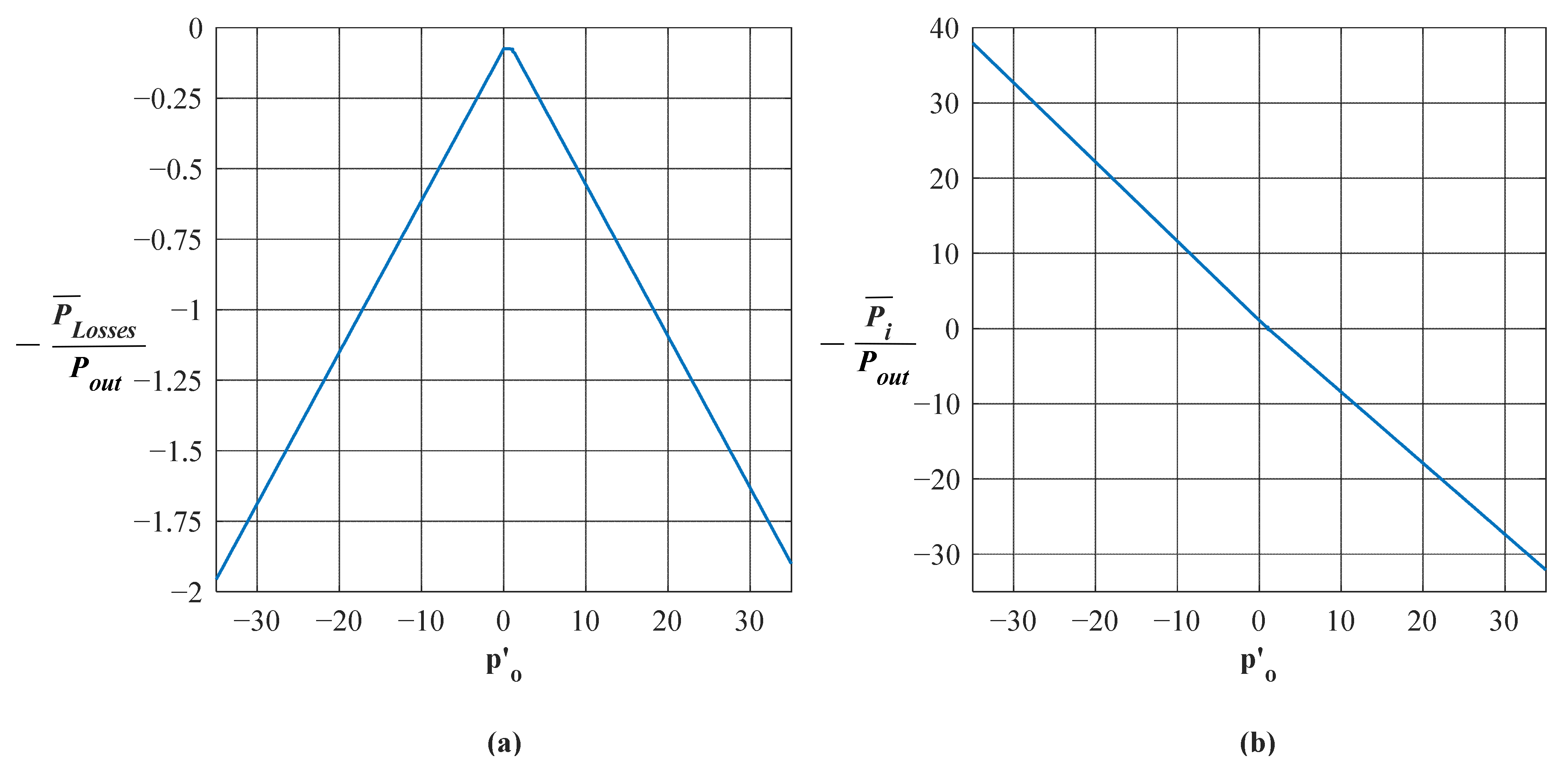
can be swiftly computed by summing Equations (2)–(4). The dimensionless power flowing in the other electric machines can be calculated by the PSU real power balance:
The results of the dimensionless analysis to FEV operation are shown in
Figure 3.
3. Identification of the Optimal Operating Maps
To carry out the analysis addressed in
Section 2, it is sufficient to know only the constructive and functional layout of the PS-CVT. This allows the calculation of the PSU speed ratios as well as the dimensionless mechanical power that electric machines should provide or absorb, by considering the PSU friction losses. More specifically, in power-split operation, the dependent variables, which are normalized to ICE speed or power, can be assessed by freely assigning the speed ratio and the power ratio between the output and the input port (
Figure 2). On the other hand, in FEV operation, the speed ratios are univocally defined, thus the dependent variables, which are normalized to the output power, can be determined by freely supposing the power ratio between one PSU port connected to an electric machine and the output port (
Figure 3). In other words, for a given vehicle speed (directly related to
) and for a given demanded torque, it is necessary to assume a specific functioning point of the ICE (in PS operation) or of one electric machine (in FEV operation) to univocally determine speeds and powers (and thus torques) on each PSU port.
Obviously, the output torque and the wheels’ speed can be considered independently one from the other, but if the output torque is higher or lower than the driving resistance, the powertrain work in dynamic operations, and the inertia of the vehicle and the propulsors should be considered in the analysis. In this article, for computational simplicity, the steady-state operation is analyzed, whereby the output torque is a function of the vehicle speed (
), thus the power delivered by the powertrain is:
where
,
,
,
are the Chevrolet Volt parameters reported in
Table 4,
is the road slope in radians,
is the gravitational acceleration, and
is the air density. It is worth noting that
is the sum of the unladen vehicle mass
and the mass of passengers, fuel, or any other additional load. Therefore,
and
depend on the driving conditions. Nonetheless, it is sufficient to modify these values upstream of the procedure described in this section so as to obtain data referred to any steady-state driving condition.
Once fixed a vehicle speed, the functioning point of the ICE in power-split operation or of one electric machine in FEV operation has to be selected so as to determine
and
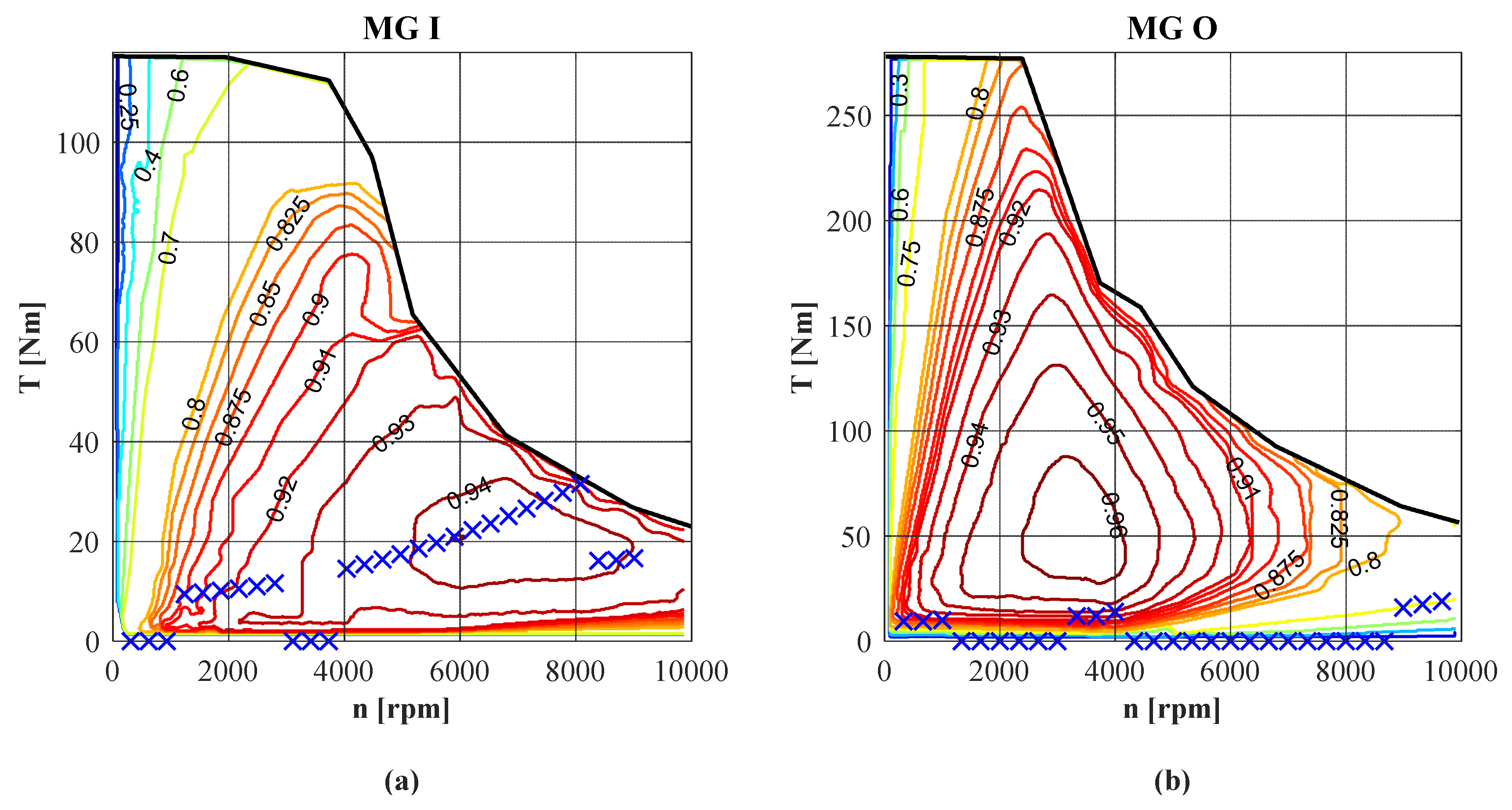
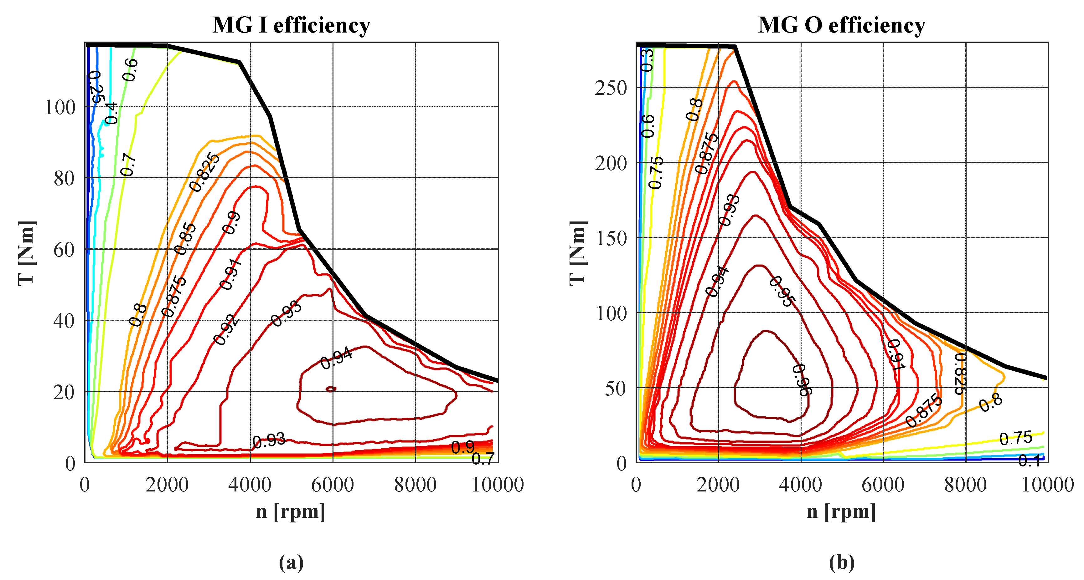
, or
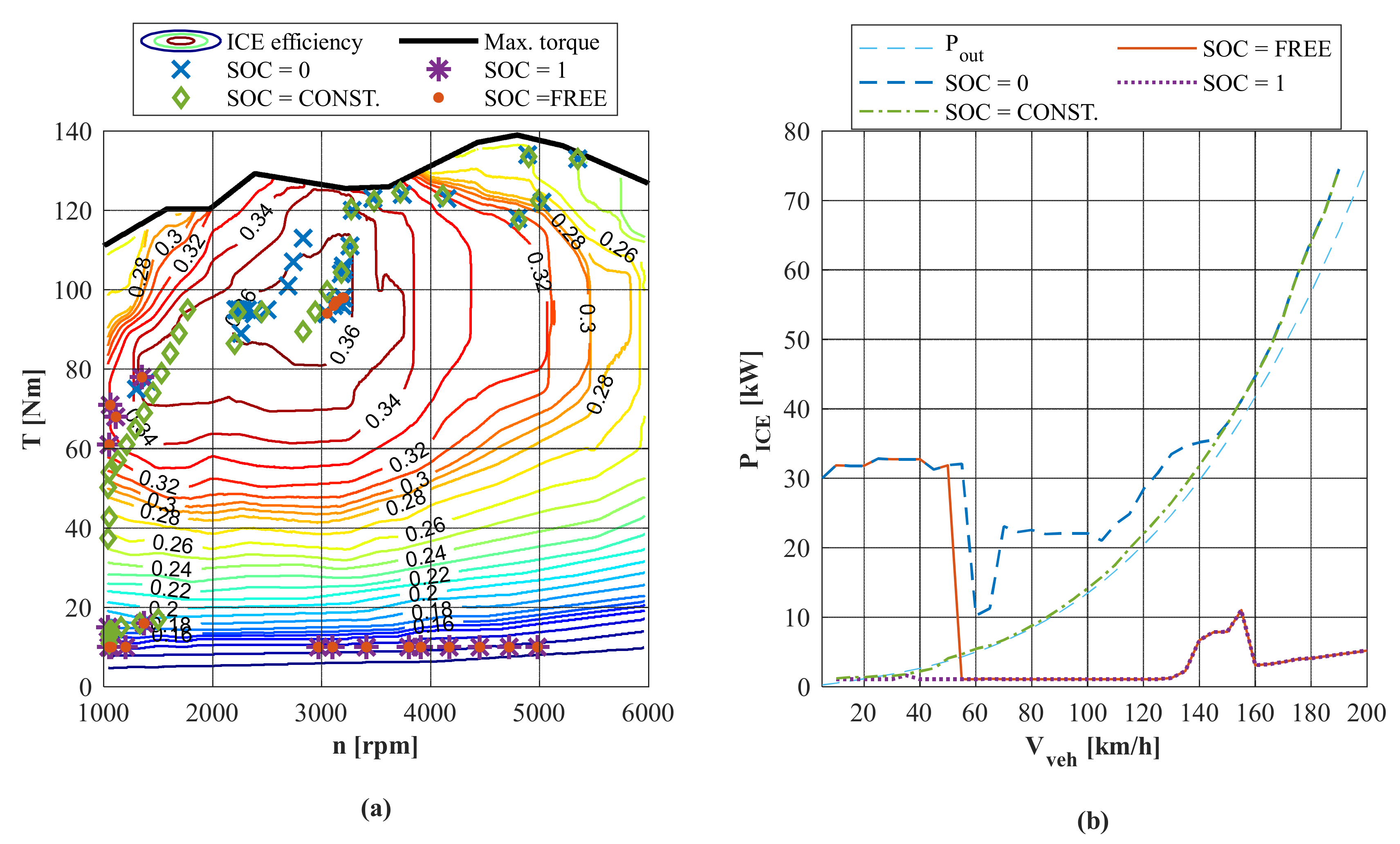
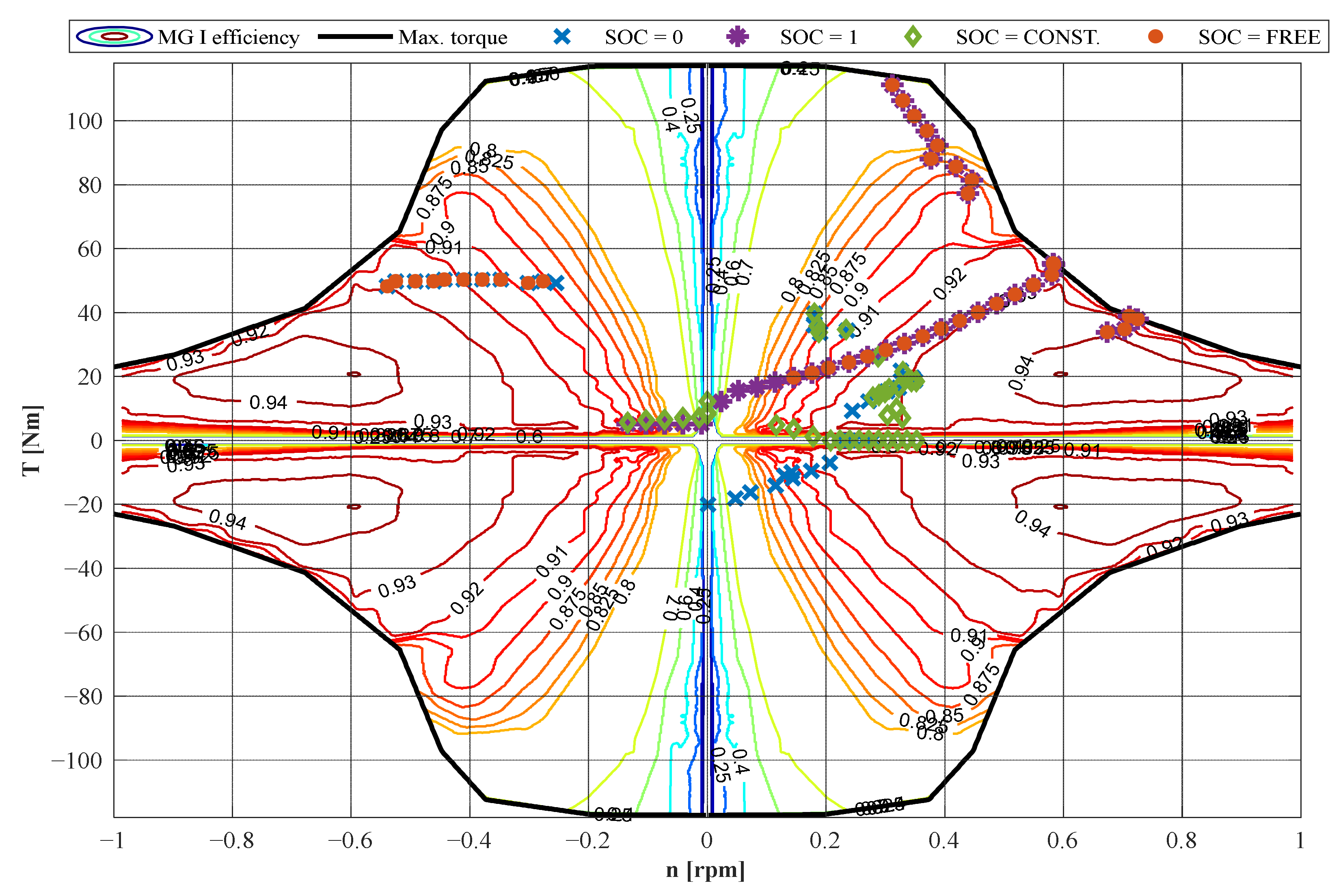
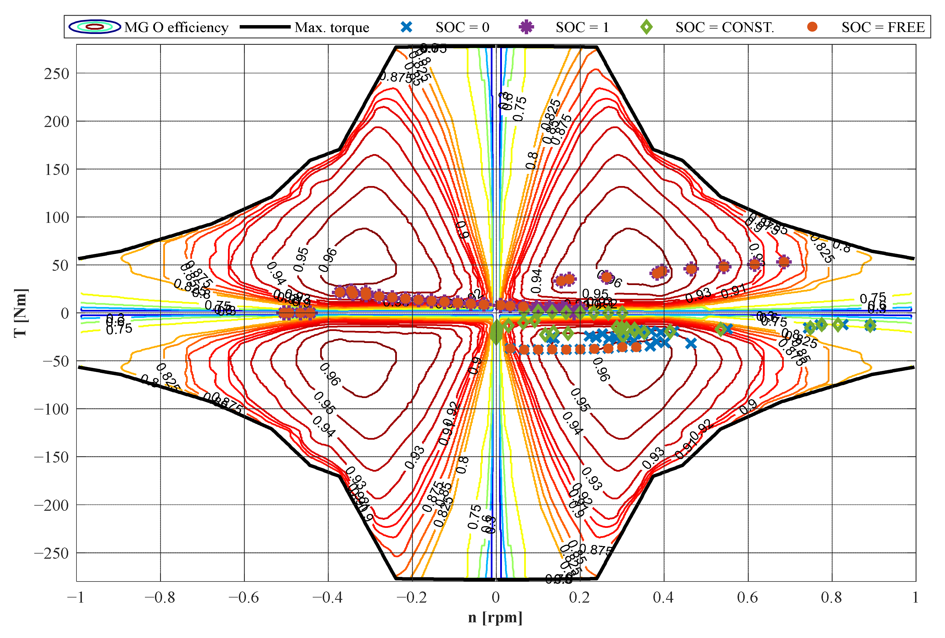
, respectively. To investigate all the viable powertrain functioning points for given vehicle speed, the whole range of operation of the ICE or MG O has to be explored. Therefore, the efficiency maps of the propulsors are needed (
Figure 4 and
Figure 5). These are necessary also for evaluating the propulsors efficiency in each achievable working point.
3.1. Calculation of Optimal Operating Maps in Power-Split Operations
For a given vehicle speed
and subsequent output power
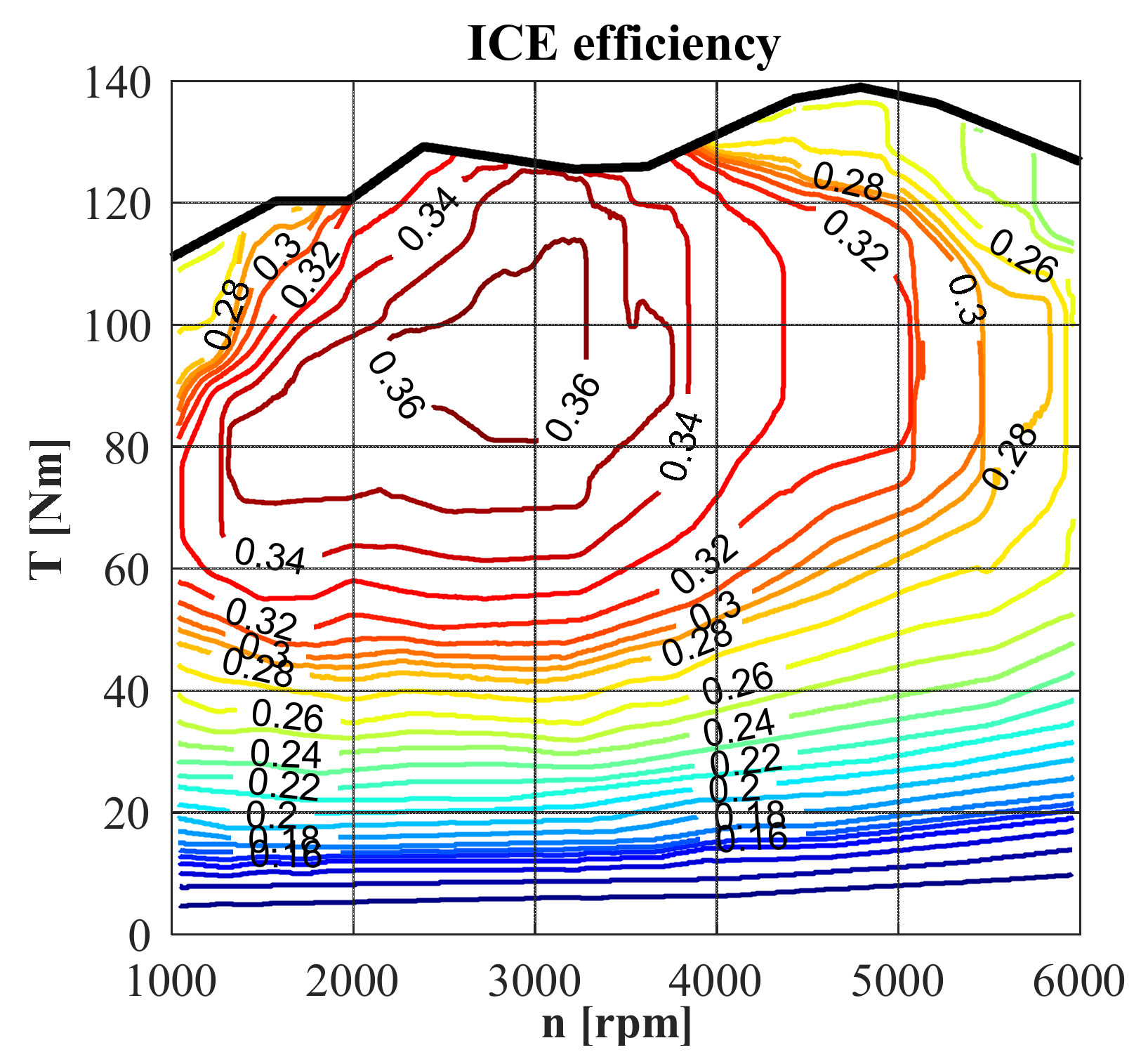
, the powertrain operation can be analyzed by considering each couple of ICE speed and torque (
,
) ranging from their minimum and maximum values within the ICE operation range of
Figure 4. This leads to the calculation of an overall speed ratio matrix, having the same dimension of the ICE efficiency map, where each element is
. A corresponding overall power ratio matrix containing
can be obtained, too. Hence, these matrices can be used to interpolate the dimensionless results of
Figure 2, in order to identify the speed and power ratios of the electric machines for each combination of
and
. Then, these ratios can be multiplied by the corresponding
and
to assess the dimensional rotational speed of the electric machines (
,
) and their mechanical power (
,
). In this way, the operating point of both electric machines is univocally determined, as is their efficiency which enables the calculation of the net electric power flowing to or from the battery as follows:
The positive sign of the power flows is shown in
Figure 1.
Hence, by the simple procedure herein addressed, it is possible to obtain a set of matrices containing all data describing the powertrain steady-state operation, which can be exploited as a basis of the desired energy management strategy. As an example, in this paper, a procedure for pursuing maximum global efficiency is proposed. According to the direction of the battery power,
can be an output or input power in the powertrain. Therefore, if
the battery supports the ICE in the vehicle propulsion, and the global efficiency is:
where
is the power provided by fuel combustion.
can be derived for each combination of
and
from
Figure 4. If
the ICE delivers power in surplus which can be used to recharge the battery, and the global efficiency is:
Eventually, it is possible to extract the maximum value from the matrix for a given vehicle speed and find the related ICE and electric machines operation resulting in the most efficient driving.
Nevertheless, the working points which violate a constructive constraint of propulsors, power converters, or batteries should not be included among the potential optimal ones. Therefore, the final operating maps do not include the functioning points whereby the ICE or electric machines operation is not included within the maps of
Figure 4 and
Figure 5, or the electric powers overcome their respective maximum limits of power converters or batteries (
Table 5).
In fact, the real constraint on
depends on the battery state of charge (SOC):
and
should be evaluated instantaneously by a deeper dynamic analysis. However, a simplified approach is exploited in the following to swiftly analyze four different scenarios, summarized in
Table 6:
SOC comprised between its lower and higher thresholds (SOC = FREE);
Battery completely discharged (SOC = 0);
Battery completely charged (SOC = 1);
Maintaining-charge driving (SOC = CONSTANT).
Table 6.
Adjusted constraints on battery power according to the SOC.
Table 6.
Adjusted constraints on battery power according to the SOC.
| SOC | [kW]
| [kW]
|
|---|
| FREE | −120 | 120 |
| 0 | −120 | 0 |
| 1 | 0 | 120 |
| CONSTANT | 0 | 0 |
3.2. Calculation of Optimal Operating Maps in FEV Operations
For given vehicle speed, in FEV driving the rotational speeds of the electric machines are univocally determined by Equation (1), therefore the only degree of freedom is the torque of one electric machine. As stated in
Section 2, by choosing as the independent variable the torque of MG O, which can range from its minimum to maximum value corresponding to each rotational speed (
Figure 5), it is possible to consider an array with different values of
. This can be used to interpolate the dimensionless results of
Figure 3b and find the potential operating points of MG I for given
and
. Then, similarly to
Section 3.1,
can be calculated by Equation (8) and the global efficiency in FEV operation is simply:
In FEV operation, the battery SOC is supposed to be always sufficient to provide the demanded power.
5. Conclusions
This article is an advancement of the previous contributions [
33,
34,
35,
36] addressing a unified parametric model for the analysis of PS-CVT. Herein it was applied to the Chevrolet Volt by introducing the propulsors efficiency maps to move from a dimensionless approach to a dimensional one. The final aim was to provide a complete and general tool to comprehensively analyze any power-split transmission, even multi-PG and multi-mode as Voltec is, by assessing also the mechanical power losses which are often neglected owing to the difficulty of their calculation. The FEV operation can also be swiftly analyzed.
As described in
Section 3 and
Section 4, this method enables the investigation of the powertrain response for given vehicle speed and demanded torque. All the viable operating points are available as a set of operating maps containing the propulsors functioning points, their efficiency, the mechanical power losses in the transmission, the battery power, and the global efficiency. These data can be exploited for the development of the desired energy management strategy.
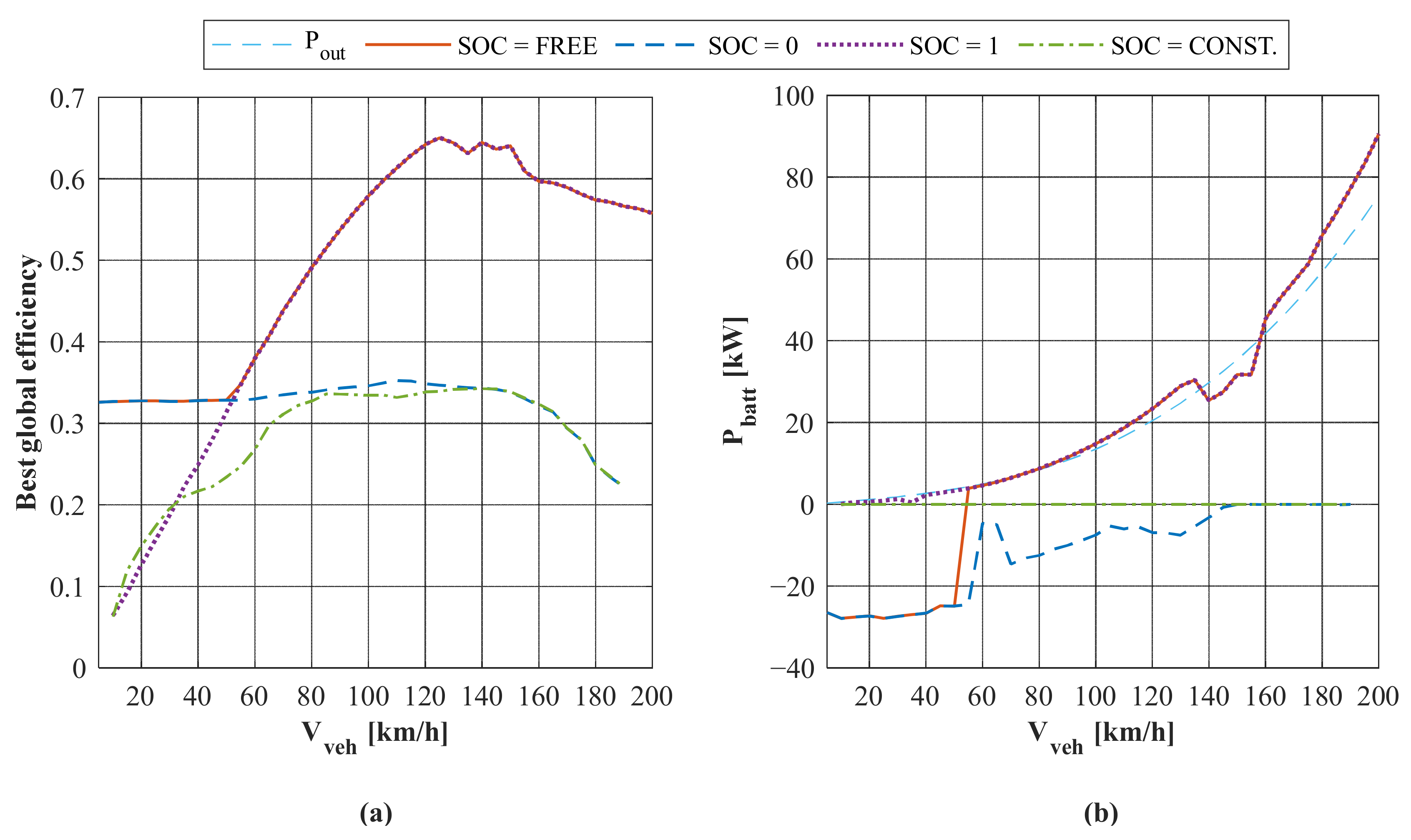
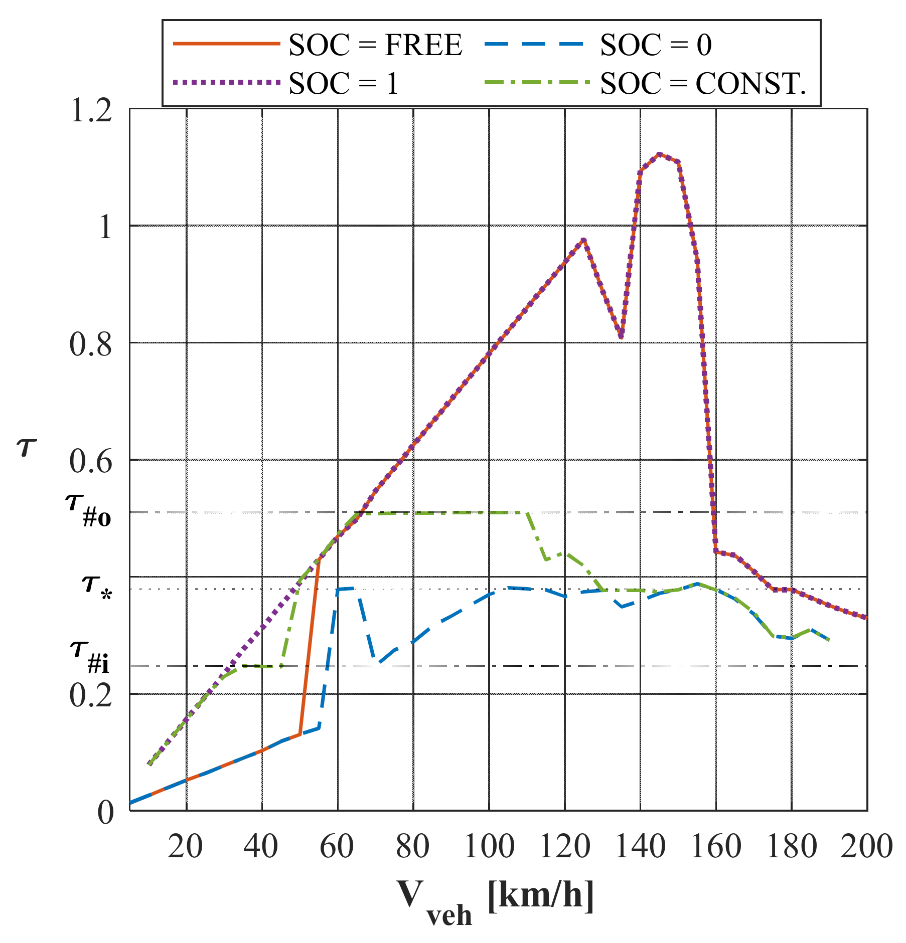
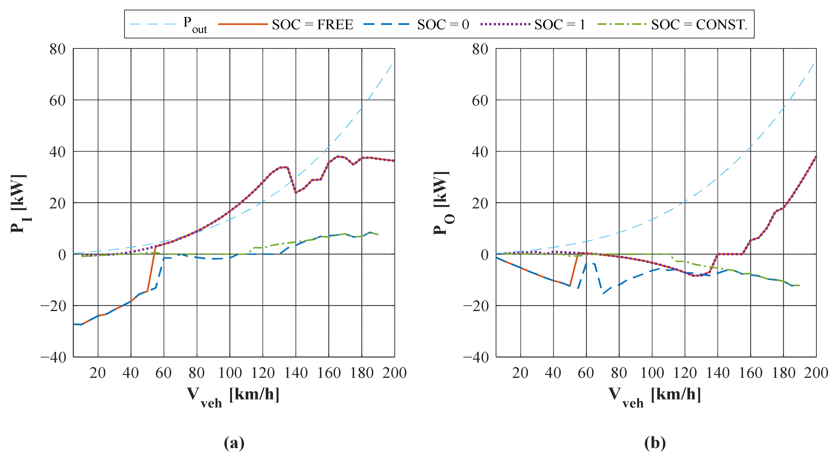
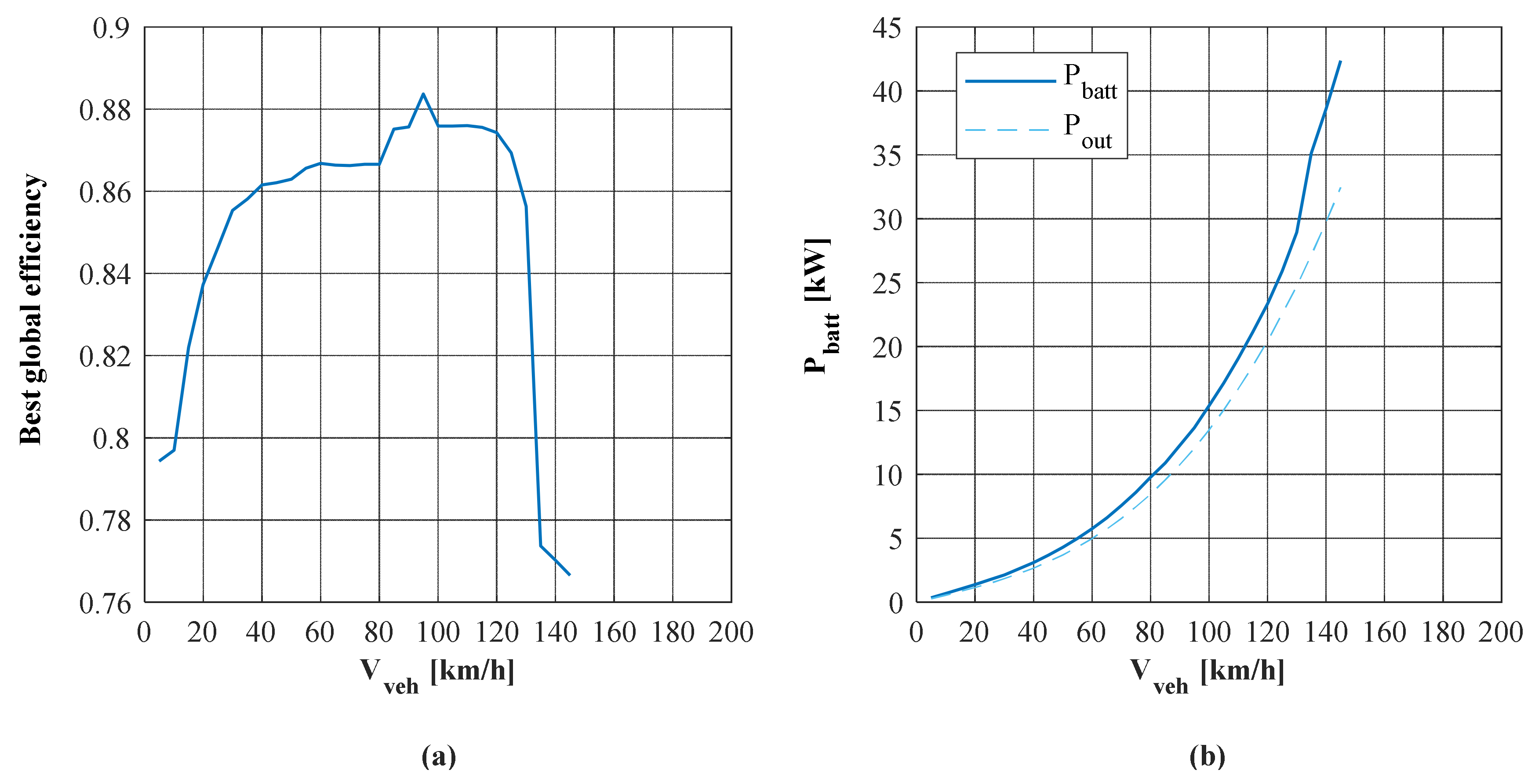
As an example, far from presenting it as an exhaustive control strategy, this paper proposes a procedure for selecting the optimal operating points which maximize the powertrain global efficiency in steady-state power-split and FEV driving. The results showed the importance of properly handling the batteries SOC to ensure the possibility of exploiting them as an energy exchanger, as well as the benefit of PGs synchronism to reduce the friction losses. Nonetheless, it seems that the MG O appears to be under-exploited in steady-state driving (
Figure 9). This can be due to the fact that the surplus power of MG O could be used to provide an acceleration boost, thus it might be exploited more in dynamic operation, which was not analyzed here.
Therefore, future research could be aimed at extending the model in this very direction. Indeed, its basic relationships between PSU speed, torque, and power ratios proposed in [
33,
35,
36] would be still valid in dynamic operation, being based on the principle of power conservation. However, the correspondence between torques developed at the PSU main ports and those provided by the propulsors would be missing because of inertial effects caused by acceleration or deceleration of the vehicle and the propulsors themselves. The extension of the model to the dynamic condition would enable a more in-depth simulation of the powertrain operation which could instantaneously consider the actual battery SOC or the power converters’ efficiency. After collecting the results of this sort of simulation, they can be used to develop the most robust energy management strategies available in the literature to optimize the desired objective function, which can be even the minimization of the mechanical power losses.


