
Bounded Attitude Control with Active Disturbance Rejection Capabilities for Multirotor UAVs

 , ,
, ,  , ,
, ,  , , and
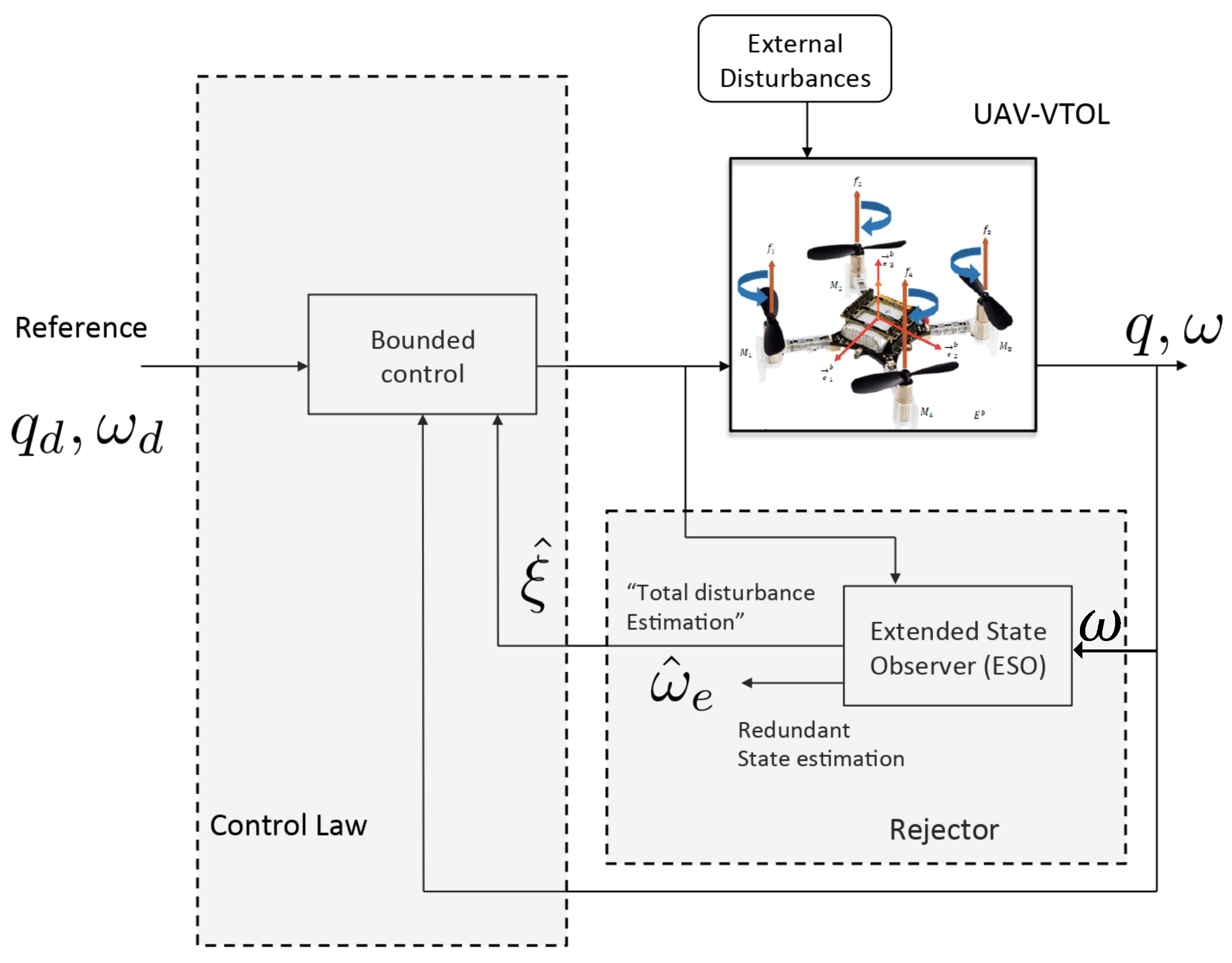
Abstract
:1. Introduction
1.1. Motivations and Background
1.2. Contributions
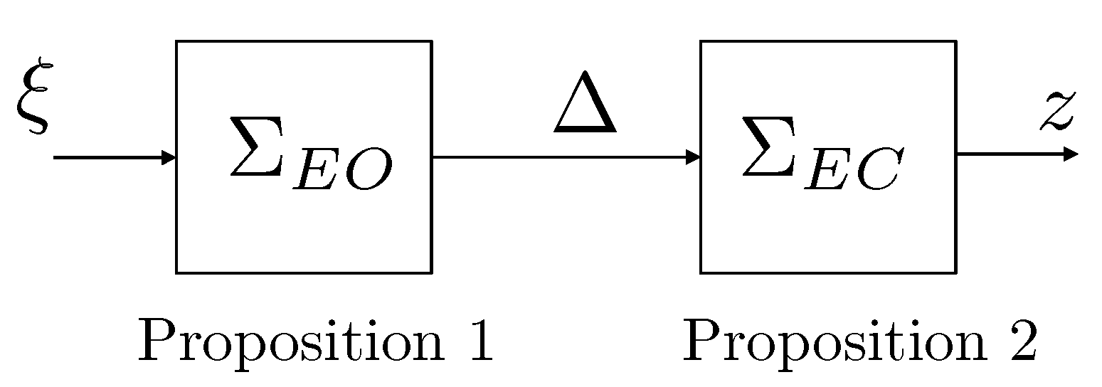
2. Preliminaries
- 1.
- It is ISS.
- 2.
- It admits an ISS-Lyapunov function.
- 3.
- It is robustly stable.
3. System Modeling and Problem Statement
3.1. Attitude Representation
3.2. Motion Equations of the Multirotor UAVs
3.3. Problem Statement
4. ADRC Design for Attitude Tracking
- and are measured, such that is always available;
- The inertia matrix is diagonal, i.e., with , and its nominal value is known;
- The perturbation function is a uniformly absolutely bounded disturbance, i.e., .
4.1. ESO Design for the Attitude Dynamics
4.2. Active Disturbance Rejection Bounded Attitude Control
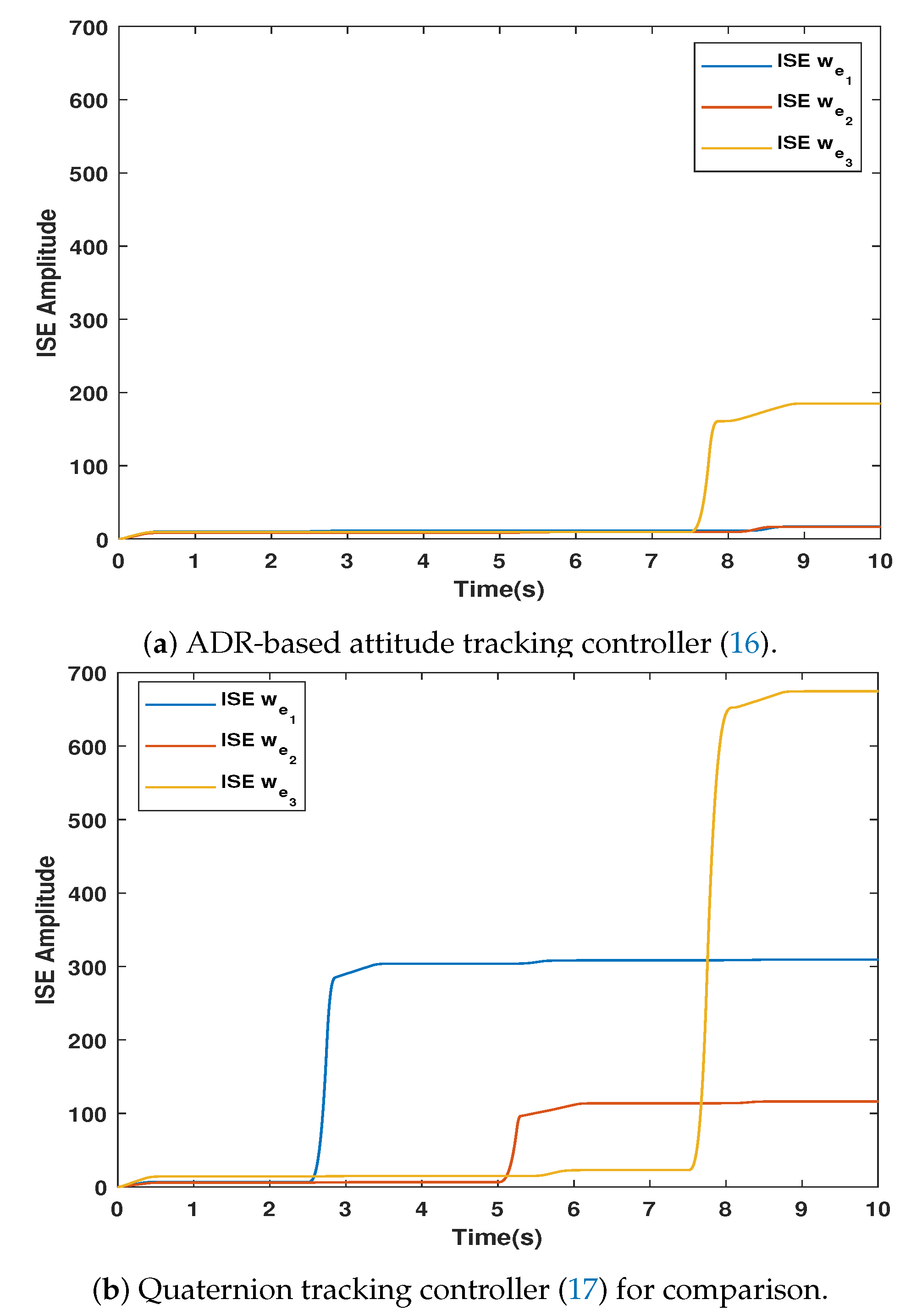
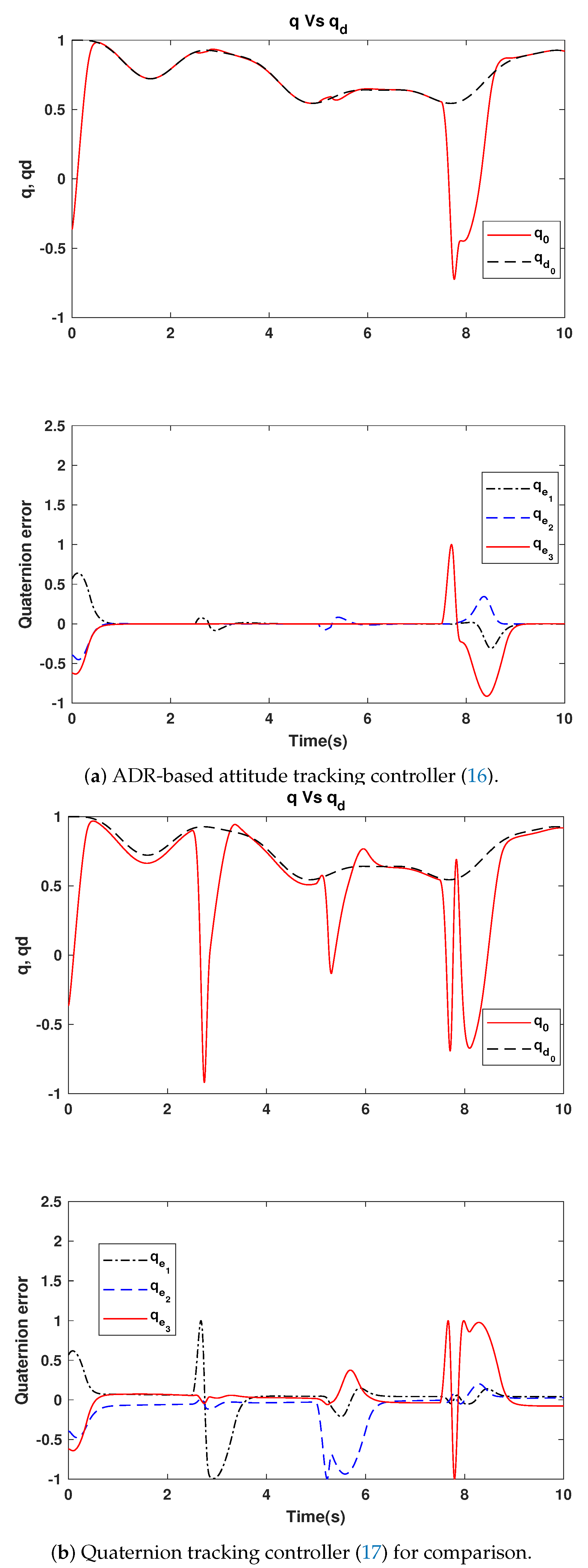
5. Simulation Results
5.1. Scenario Description
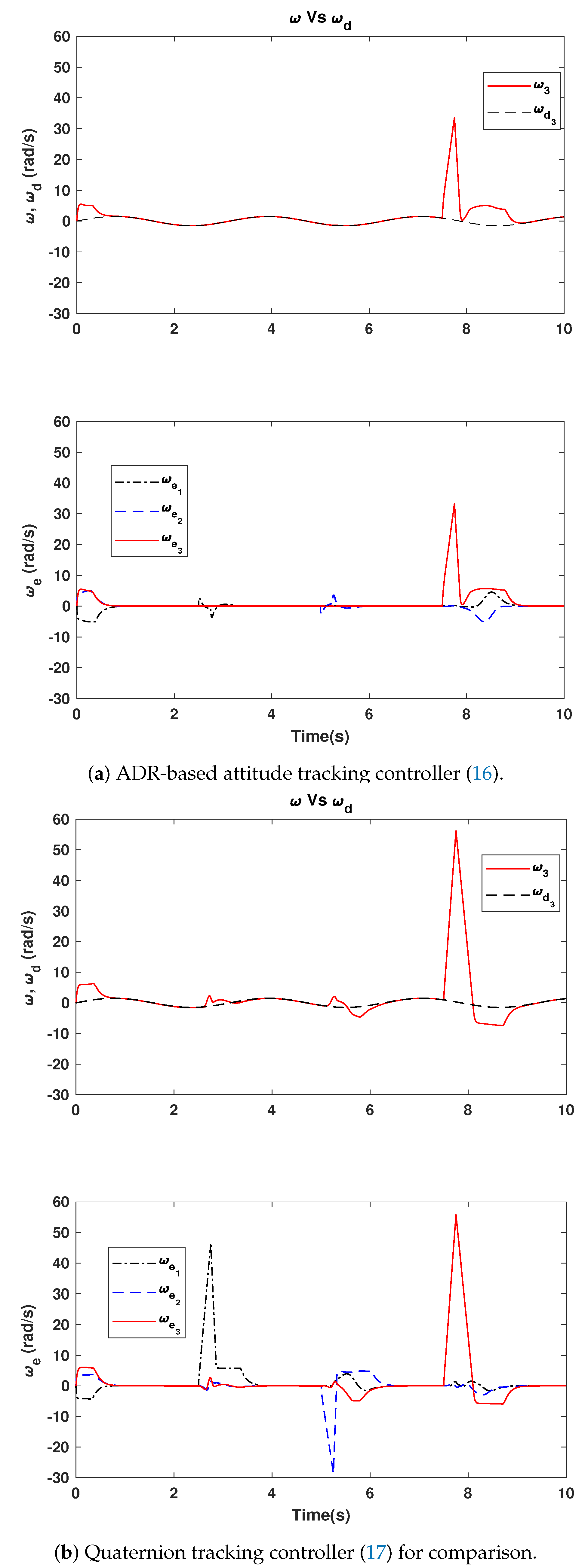
5.2. Quaternion and Angular Velocity Evolution
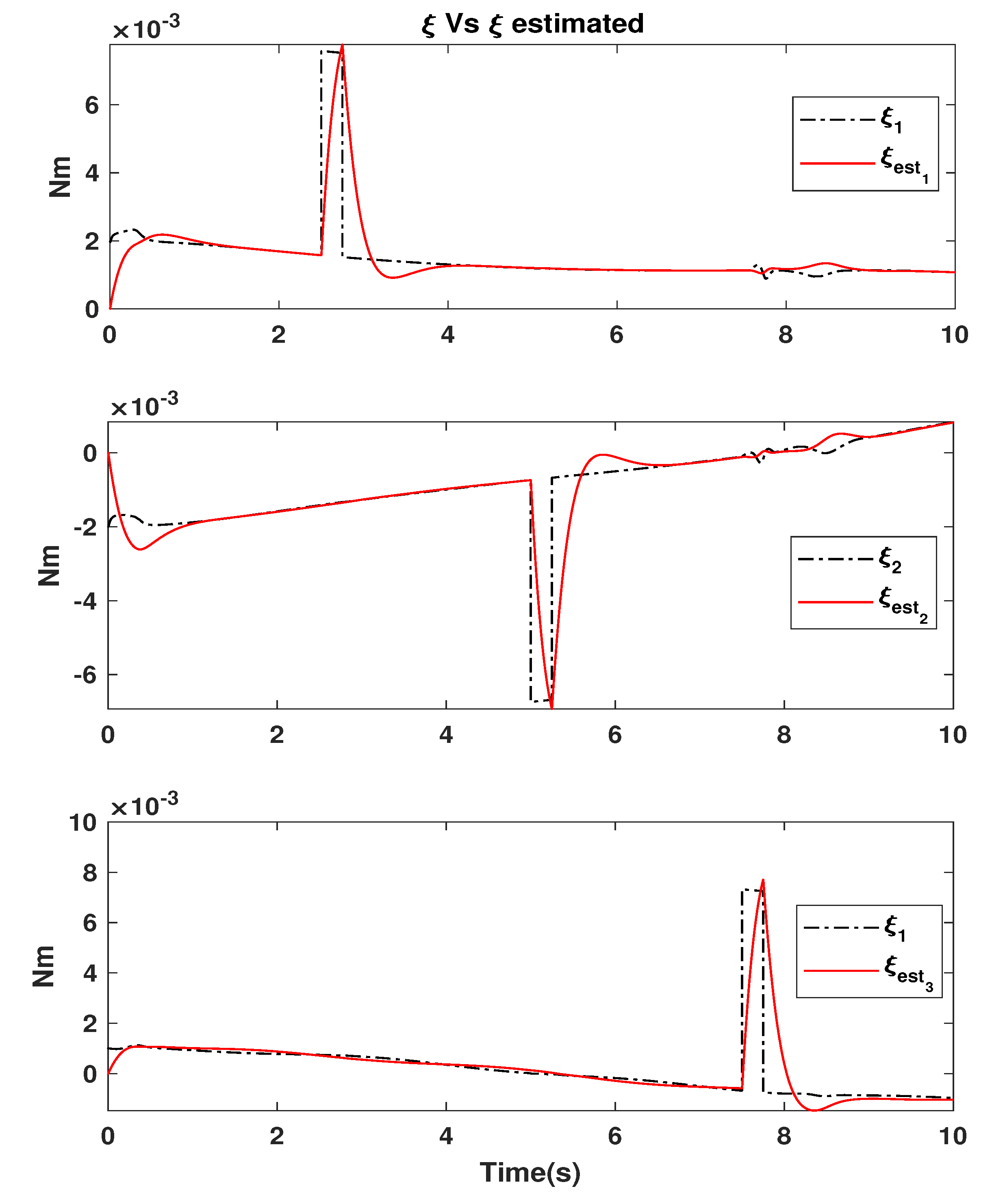
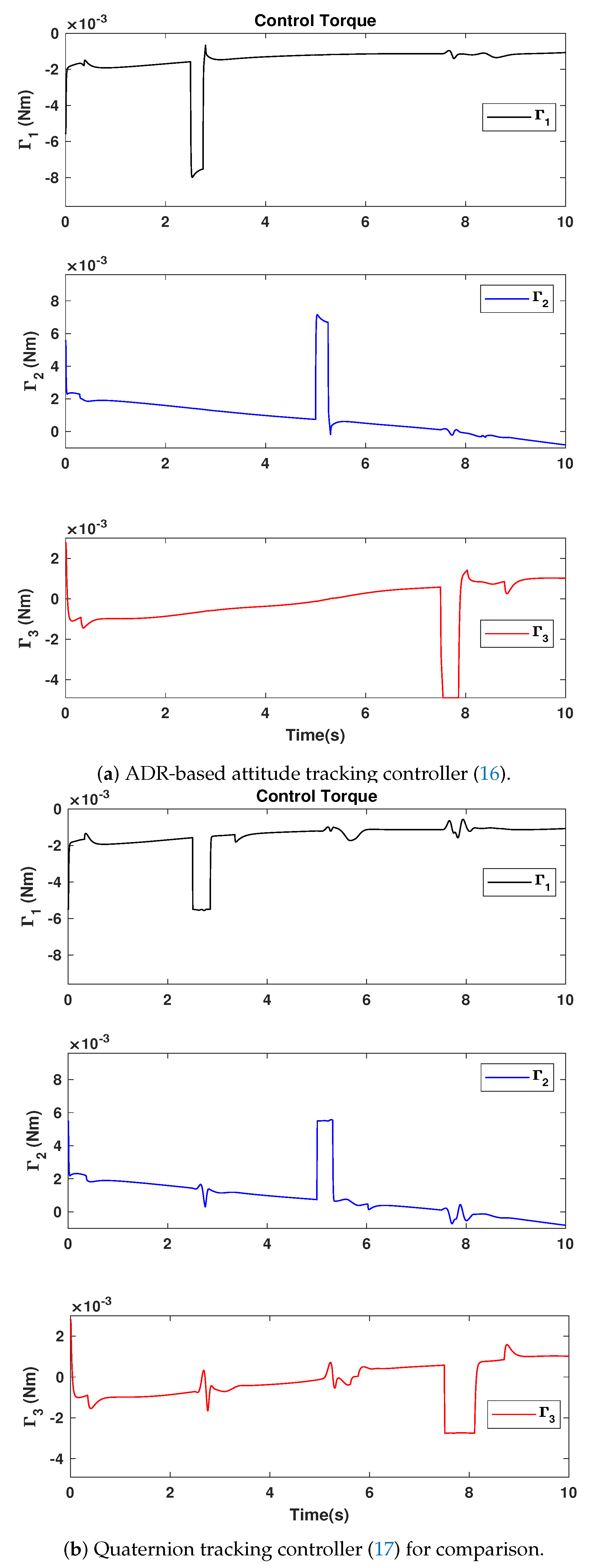
5.3. Disturbance Estimation and Rejection
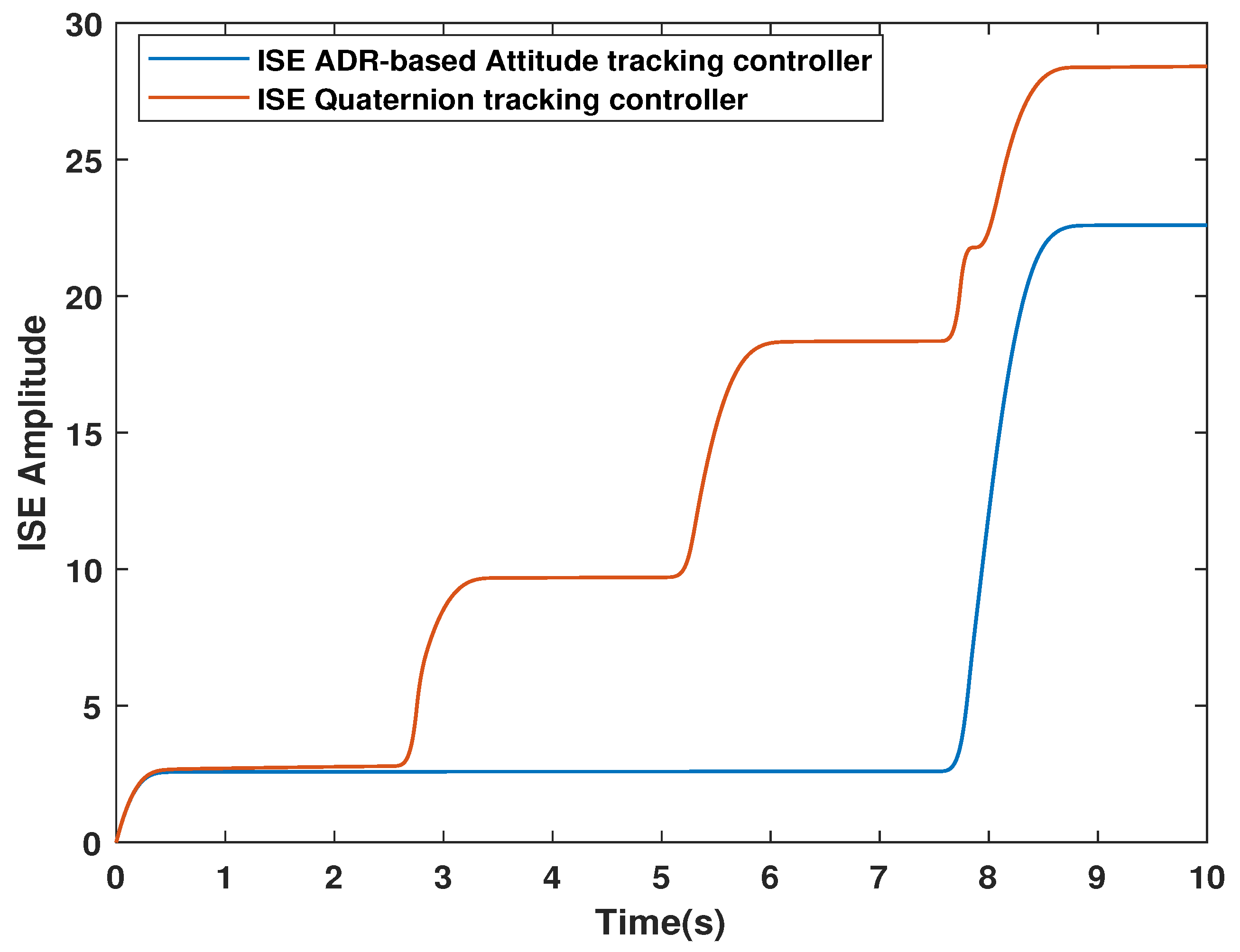
5.4. Performance Analysis
6. Conclusions
Author Contributions
Funding
Institutional Review Board Statement
Informed Consent Statement
Data Availability Statement
Conflicts of Interest
Appendix A. Proof of Proposition 1
Appendix B. Proof of Proposition 2
References
- Castillo, P.; Lozano, R.; Dzul, A. Stabilization of a mini rotorcraft with four rotors. IEEE Control Syst. Mag. 2005, 25, 45–55. [Google Scholar]
- Tayebi, A.; McGilvray, S. Attitude stabilization of a VTOL quadrotor aircraft. IEEE Trans. Control Syst. Technol. 2006, 14, 562–571. [Google Scholar] [CrossRef] [Green Version]
- Guerrero-Castellanos, J.F.; Marchand, N.; Hably, A.; Lesecq, S.; Delamare, J. Bounded attitude control of rigid bodies: Real-time experimentation to a quadrotor mini-helicopter. Control Eng. Pract. 2011, 19, 790–797. [Google Scholar] [CrossRef] [Green Version]
- The-Robot Report. Unmanned Aerial Systems/Drones. 2021. Available online: https://www.therobotreport.com (accessed on 28 April 2021).
- Mahony, R.; Kumar, V.; Corke, P. Multirotor Aerial Vehicles: Modeling, Estimation, and Control of Quadrotor. IEEE Robot. Autom. Mag. 2012, 19, 20–32. [Google Scholar] [CrossRef]
- Hua, M.D.; Hamel, T.; Morin, P.; Samson, C. Introduction to feedback control of underactuated VTOLvehicles: A review of basic control design ideas and principles. IEEE Control Syst. Mag. 2013, 33, 61–75. [Google Scholar]
- Aström, K.; Murray, R. Feedback Systems: An Introduction for Scientists and Engineers; Princeton University Press: Princeton, NJ, USA; Oxford, UK, 2008. [Google Scholar]
- Demirhan, M.; Premachandra, C. Development of an Automated Camera-Based Drone Landing System. IEEE Access 2020, 8, 202111–202121. [Google Scholar] [CrossRef]
- Premachandra, C.; Thanh, D.N.H.; Kimura, T.; Kawanaka, H. A study on hovering control of small aerial robot by sensing existing floor features. IEEE/CAA J. Autom. Sin. 2020, 7, 1016–1025. [Google Scholar] [CrossRef]
- Shehzad, M.F.; Bilal, A.; Ahmad, H. Position Attitude Control of an Aerial Robot (Quadrotor) With Intelligent PID and State feedback LQR Controller: A Comparative Approach. In Proceedings of the 2019 16th International Bhurban Conference on Applied Sciences and Technology (IBCAST), Islamabad, Pakistan, 8–12 January 2019; pp. 340–346. [Google Scholar] [CrossRef]
- Chen, Y.; Zhao, Y. The design of the four rotor unmanned aircraft control algorithm. In Proceedings of the 2017 29th Chinese Control And Decision Conference (CCDC), Chongqing, China, 28–30 May 2017; pp. 5146–5150. [Google Scholar] [CrossRef]
- Han, J. From PID to Active Disturbance Rejection Control. Trans. Ind. Electron. 2009, 56, 900–906. [Google Scholar] [CrossRef]
- Peng, X.; Guo, K.; Geng, Z. Full State Tracking and Formation Control for Under-Actuated VTOL UAVs. IEEE Access 2019, 7, 3755–3766. [Google Scholar] [CrossRef]
- Du, H.; Zhu, W.; Wen, G.; Duan, Z.; Lü, J. Distributed Formation Control of Multiple Quadrotor Aircraft Based on Nonsmooth Consensus Algorithms. IEEE Trans. Cybern. 2019, 49, 342–353. [Google Scholar] [CrossRef] [PubMed]
- Guerrero-Castellanos, J.; Vega-Alonzo, A.; Durand, S.; Marchand, N.; Gonzalez-Diaz, V.; Castañeda-Camacho, J.; Guerrero-Sánchez, W. Leader-Following Consensus and Formation Control of VTOL-UAVs with Event-Triggered Communications. Sensors 2019, 19, 5498. [Google Scholar] [CrossRef] [Green Version]
- Alvarez-Munoz, J.; Marchand, N.; Guerrero-Castellanos, J.F.; Tellez-Guzman, J.J.; Escareno, J.; Rakotondrabe, M. Rotorcraft with a 3DOF Rigid Manipulator: Quaternion-based Modeling and Real-time Control Tolerant to Multi-body Couplings. Int. J. Autom. Comput. 2018, 15, 547–558. [Google Scholar] [CrossRef] [Green Version]
- Mohammadi, K.; Jafarinasab, M.; Sirouspour, S.; Dyer, E. Decentralized Motion Control in a Cabled-based Multi-drone Load Transport System. In Proceedings of the 2018 IEEE/RSJ International Conference on Intelligent Robots and Systems (IROS), Madrid, Spain, 1–5 October 2018; pp. 4198–4203. [Google Scholar]
- Bandala, A.A.; Chua, A.G.; Dajay, R.R.; Rabacca, R.D.; So, E.C.; Martin, Z.; Maningo, J.; Fernando, A.H.; Rhay, P.; Vicerra, R. Payload Lift and Transport Using Decentralized Unmanned Aerial Vehicle Quadcopter Teams. In Proceedings of the TENCON 2018—2018 IEEE Region 10 Conference, Jeju, Korea, 28–31 October 2018; pp. 1695–1700. [Google Scholar]
- Klausen, K.; Meissen, C.; Fossen, T.I.; Arcak, M.; Johansen, T.A. Cooperative Control for Multirotors Transporting an Unknown Suspended Load Under Environmental Disturbances. IEEE Trans. Control Syst. Technol. 2020, 28, 653–660. [Google Scholar] [CrossRef] [Green Version]
- Leonard, F.; Martini, A.; Abba, G. Robust Nonlinear Controls of Model-Scale Helicopters Under Lateral and Vertical Wind Gusts. IEEE Trans. Control Syst. Technol. 2012, 20, 154–163. [Google Scholar] [CrossRef]
- Escareño, J.; Salazar, S.; Romero, H.; Lozano, R. Trajectory Control of a Quadrotor Subject to 2D Wind Disturbances. J. Intell. Robot. Syst. 2013, 70, 51–63. [Google Scholar] [CrossRef] [Green Version]
- Naldi, R.; Furci, M.; Sanfelice, R.G.; Marconi, L. Robust Global Trajectory Tracking for Underactuated VTOL Aerial Vehicles Using Inner-Outer Loop Control Paradigms. IEEE Trans. Autom. Control 2017, 62, 97–112. [Google Scholar] [CrossRef] [Green Version]
- Li, S.; Yang, J.; Chen, W.H.; Chen, X. Disturbance Observer-Based Control: Methods and Applications; CRC Press: Boca Raton, FL, USA; London, UK; New York, NY, USA, 2014. [Google Scholar]
- Chen, W.H.; Yang, J.; Guo, L.; Li, S. Disturbance-Observer-Based Control and Related Methods—An Overview. IEEE Trans. Ind. Electron. 2016, 63, 1083–1095. [Google Scholar] [CrossRef] [Green Version]
- Mohammadi, A.; Marquez, H.J.; Tavakoli, M. Nonlinear Disturbance Observers: Design and Applications to Euler-Lagrange Systems. IEEE Control Syst. Mag. 2017, 37, 50–72. [Google Scholar]
- Chen, Z.; Huang, J. Attitude Tracking and Disturbance Rejection of Rigid Spacecraft by Adaptive Control. IEEE Trans. Autom. Control 2009, 54, 600–605. [Google Scholar] [CrossRef]
- Liu, H.; Wang, X. Quaternion-based robust attitude control for quadrotors. In Proceedings of the 2015 International Conference on Unmanned Aircraft Systems (ICUAS), Denver, CO, USA, 9–12 June 2015; pp. 920–925. [Google Scholar]
- Wang, X.; Shirinzadeh, B.; Ang, M.H. Nonlinear Double-Integral Observer and Application to Quadrotor Aircraft. IEEE Trans. Ind. Electron. 2015, 62, 1189–1200. [Google Scholar] [CrossRef]
- Sanz, R.; Garcia, P.; Zhong, Q.C.; Albertos, P. Robust Control of Quadrotors Based on an Uncertainty and Disturbance Estimator. J. Dyn. Syst. Meas. Control 2016, 138, 071006. [Google Scholar] [CrossRef]
- Liu, H.; Zhao, W.; Zuo, Z.; Zhong, Y. Robust Control for Quadrotors With Multiple Time-Varying Uncertainties and Delays. IEEE Trans. Ind. Electron. 2017, 64, 1303–1312. [Google Scholar] [CrossRef]
- Castillo, A.; Sanz, R.; Garcia, P.; Qiu, W.; Wang, H.; Xu, C. Disturbance observer-based quadrotor attitude tracking control for aggressive maneuvers. Control Eng. Pract. 2019, 82, 14–23. [Google Scholar] [CrossRef]
- Zhang, J.; Zhao, W.; Shen, G.; Xia, Y. Disturbance Observer-Based Adaptive Finite-Time Attitude Tracking Control for Rigid Spacecraft. IEEE Trans. Syst. Man Cybern. Syst. 2020, 1–8. [Google Scholar] [CrossRef]
- McKinnon, C.D.; Schoellig, A.P. Estimating and reacting to forces and torques resulting from common aerodynamic disturbances acting on quadrotors. Robot. Auton. Syst. 2020, 123, 103314. [Google Scholar] [CrossRef]
- Freidovich, L.B.; Khalil, H.K. Performance recovery of feedback-linearization-based designs. IEEE Trans. Autom. Control 2008, 53, 2324–2334. [Google Scholar] [CrossRef]
- Guo, B.Z.; Zhao, Z.L. Active Disturbance Rejection Control for Nonlinear Systems: An Introduction; John Wiley & Sons (Asia) Pte Ltd.: Singapore, 2016. [Google Scholar] [CrossRef]
- Orozco-Soto, S.M.; Ibarra-Zannatha, J.M. Motion control of humanoid robots using sliding mode observer-based active disturbance rejection control. In Proceedings of the IEEE Colombian Conference on Automatic Control (CCAC), Cartagena, Colombia, 18–20 October 2017; pp. 1–8. [Google Scholar]
- Chalawane, H.; Essadki, A.; Nasser, T.; Arbaoui, M. A new robust control based on active disturbance rejection controller for speed sensorless induction motor. In Proceedings of the 2017 International Conference on Electrical and Information Technologies (ICEIT), Rabat, Morocco, 15–18 November 2017; pp. 1–6. [Google Scholar] [CrossRef]
- Yin, Z.; Wang, P. Methods to suppress voltage ripple of fast charging of electric vehicle based on active disturbance rejection control technique. In Proceedings of the 2017 3rd IEEE International Conference on Control Science and Systems Engineering (ICCSSE), Beijing, China, 17–19 August 2017; pp. 760–765. [Google Scholar] [CrossRef]
- Hernandez-Méndez, A.; Linares-Flores, J.; Sira-Ramírez, H.; Guerrero-Castellanos, J.; Mino-Aguilar, G. A Backstepping Approach to Decentralized Active Disturbance Rejection Control of Interacting Boost Converters. Trans. Ind. Appl. 2017, 53, 4063–4072. [Google Scholar] [CrossRef]
- Sira-Ramírez, H.; Luviano-Juárez, A.; Ramírez-Neria, M.; Zurita-Bustamante, E.W. Active Disturbance Rejection Control of Dynamic Systems: A Flatness-Based Approach; Butterworth-Heinemann: Oxford, UK, 2017. [Google Scholar]
- Zhu, G.; Qi, J.; Wu, C. Landing Control of Fixed-wing UAV Based on ADRC. In Proceedings of the 2019 Chinese Control Conference (CCC), Guangzhou, China, 27–30 July 2019; pp. 8020–8025. [Google Scholar] [CrossRef]
- Xu, Y.; Luo, W.; Zhang, L. Research on control system of quadrotor based on ADRC. In Proceedings of the 2018 Chinese Control And Decision Conference (CCDC), Shenyang, China, 9–11 June 2018; pp. 2966–2971. [Google Scholar] [CrossRef]
- Ma, Z.; Jiao, S.M. Research on the attitude control of quad-rotor UAV based on active disturbance rejection control. In Proceedings of the 2017 3rd IEEE International Conference on Control Science and Systems Engineering (ICCSSE), Beijing, China, 17–19 August 2017; pp. 45–49. [Google Scholar] [CrossRef]
- Qin, L.; Zhou, W.; Li, L.; Jiang, W. Active disturbance rejection control system design for quadrotor. In Proceedings of the 2017 36th Chinese Control Conference (CCC), Dalian, China, 26–28 July 2017. [Google Scholar]
- Chang, K.; Xia, Y.; Huang, K.; Ma, D. Obstacle avoidance and active disturbance rejection control for a quadrotor. Neurocomputing 2016, 190, 60–69. [Google Scholar] [CrossRef]
- Castillo, A.; Sanz, R.; Garcia, P.; Albertos, P. A quaternion-based and active disturbance rejection attitude control for quadrotor. In Proceedings of the 2016 IEEE International Conference on Information and Automation (ICIA), Ningbo, China, 1–3 August 2016; pp. 240–245. [Google Scholar]
- Song, Z.; Wang, Y.; Liu, L.; Cheng, Z.; Yang, Y. Research on Attitude Control of Quadrotor UAV Based on Active Disturbance Rejection Control. In Proceedings of the 2020 Chinese Control And Decision Conference (CCDC), Hefei, China, 22–24 August 2020; pp. 5051–5056. [Google Scholar]
- Zhang, Y.; Chen, Z.; Sun, M. Trajectory tracking control for a quadrotor unmanned aerial vehicle based on dynamic surface active disturbance rejection control. Trans. Inst. Meas. Control 2020, 42, 2198–2205. [Google Scholar] [CrossRef]
- Xiong, H.; Yi, J.q.; Fan, G.l.; Jing, F.s.; Yuan, R.y. Autolanding of unmanned aerial vehicles based on Active Disturbance Rejection Control. In Proceedings of the IEEE International Conference on Intelligent Computing and Intelligent Systems (ICIS 2009), Shanghai, China, 20–22 November 2009; Volume 2, pp. 772–776. [Google Scholar]
- Ping, Y.; Qi, J.; Wu, C. Quadrotor Transporting Cable Suspended Load using ADRC. In Proceedings of the 2019 Chinese Control Conference (CCC), Guangzhou, China, 27–30 July 2019; pp. 8008–8013. [Google Scholar] [CrossRef]
- Ma, D.; Xia, Y.; Li, T.; Chang, K. Active disturbance rejection and predictive control strategy for a quadrotor helicopter. IET Control Theory Appl. 2016, 10, 2213–2222. [Google Scholar] [CrossRef]
- Sontag, E.D. Input to State Stability: Basic Concepts and Results. In Nonlinear and Optimal Control Theory: Lectures Given at the C.I.M.E. Summer School held in Cetraro, Italy, 19–29 June 2004; Nistri, P., Stefani, G., Eds.; Springer: Berlin/Heidelberg, Germany, 2008; pp. 163–220. [Google Scholar] [CrossRef]
- Nicotra, M.M.; Garone, E.; Naldi, R.; Marconi, L. Nested saturation control of an UAV carrying a suspended load. In Proceedings of the 2014 American Control Conference, Portland, OR, USA, 4–6 June 2014; pp. 3585–3590. [Google Scholar] [CrossRef]
- Sontag, E.; Wang, Y. On characterizations of the input-to-state stability property. Syst. Control Lett. 1995, 24, 351–359. [Google Scholar] [CrossRef]
- Shuster, M.D. A survey of attitude representations. Navigation 1993, 8, 439–517. [Google Scholar]
- Schlanbusch, R.; Loria, A.; Nicklasson, P.J. On the stability and stabilization of quaternion equilibria of rigid bodies. Automatica 2012, 48, 3135–3141. [Google Scholar] [CrossRef] [Green Version]
- Garone, E.; Nicotra, M.M. Explicit Reference Governor for Constrained Nonlinear Systems. IEEE Trans. Autom. Control 2016, 61, 1379–1384. [Google Scholar] [CrossRef]
- Clark, R. Integral of the error squared as a performance index for automatic control systems. Trans. Am. Inst. Electr. Eng. Part II Appl. Ind. 1961, 79, 467–471. [Google Scholar] [CrossRef]
- Marchand, N.; Durand, S.; Guerrero-Castellanos, J.F. A general formula for event-based stabilization of nonlinear systems. Trans. Autom. Control 2012, 58, 1332–1337. [Google Scholar] [CrossRef] [Green Version]
- Guerrero-Castellanos, J.F.; Téllez-Guzmán, J.J.; Durand, S.; Marchand, N.; Alvarez-Muñoz, J.U.; González-Díaz, V.R. Attitude Stabilization of a Quadrotor by Means of Event-Triggered Nonlinear Control. J. Intell. Robot. Syst. 2014, 73, 123–135. [Google Scholar] [CrossRef] [Green Version]
- Kia, S.S.; Van Scoy, B.; Cortes, J.; Freeman, R.A.; Lynch, K.M.; Martinez, S. Tutorial on Dynamic Average Consensus: The Problem, Its Applications, and the Algorithms. IEEE Control Syst. Mag. 2019, 39, 40–72. [Google Scholar] [CrossRef] [Green Version]


Publisher’s Note: MDPI stays neutral with regard to jurisdictional claims in published maps and institutional affiliations. |
© 2021 by the authors. Licensee MDPI, Basel, Switzerland. This article is an open access article distributed under the terms and conditions of the Creative Commons Attribution (CC BY) license (https://creativecommons.org/licenses/by/4.0/).
Share and Cite
Guerrero-Castellanos, J.F.; Durand, S.; Munoz-Hernandez, G.A.; Marchand, N.; Romeo, L.L.G.; Linares-Flores, J.; Mino-Aguilar, G.; Guerrero-Sánchez, W.F. Bounded Attitude Control with Active Disturbance Rejection Capabilities for Multirotor UAVs. Appl. Sci. 2021, 11, 5960. https://doi.org/10.3390/app11135960
Guerrero-Castellanos JF, Durand S, Munoz-Hernandez GA, Marchand N, Romeo LLG, Linares-Flores J, Mino-Aguilar G, Guerrero-Sánchez WF. Bounded Attitude Control with Active Disturbance Rejection Capabilities for Multirotor UAVs. Applied Sciences. 2021; 11(13):5960. https://doi.org/10.3390/app11135960
Chicago/Turabian StyleGuerrero-Castellanos, José Fermi, Sylvain Durand, German Ardul Munoz-Hernandez, Nicolas Marchand, Lorenzo L. González Romeo, Jesús Linares-Flores, Gerardo Mino-Aguilar, and Wuiyevaldo F. Guerrero-Sánchez. 2021. "Bounded Attitude Control with Active Disturbance Rejection Capabilities for Multirotor UAVs" Applied Sciences 11, no. 13: 5960. https://doi.org/10.3390/app11135960
APA StyleGuerrero-Castellanos, J. F., Durand, S., Munoz-Hernandez, G. A., Marchand, N., Romeo, L. L. G., Linares-Flores, J., Mino-Aguilar, G., & Guerrero-Sánchez, W. F. (2021). Bounded Attitude Control with Active Disturbance Rejection Capabilities for Multirotor UAVs. Applied Sciences, 11(13), 5960. https://doi.org/10.3390/app11135960