Abstract
Aiming at addressing the problem that the joints are easily destroyed by the impact torque during the process of space robot on-orbit capturing a non-cooperative spacecraft, a reinforcement learning control algorithm combined with a compliant mechanism is proposed to achieve buffer compliance control. The compliant mechanism can not only absorb the impact energy through the deformation of its internal spring, but also limit the impact torque to a safe range by combining with the compliance control strategy. First of all, the dynamic models of the space robot and the target spacecraft before capture are obtained by using the Lagrange approach and Newton-Euler method. After that, based on the law of conservation of momentum, the constraints of kinematics and velocity, the integrated dynamic model of the post-capture hybrid system is derived. Considering the unstable hybrid system, a buffer compliance control based on reinforcement learning is proposed for the stable control. The associative search network is employed to approximate unknown nonlinear functions, an adaptive critic network is utilized to construct reinforcement signal to tune the associative search network. The numerical simulation shows that the proposed control scheme can reduce the impact torque acting on joints by 76.6% at the maximum and 58.7% at the minimum in the capturing operation phase. And in the stable control phase, the impact torque acting on the joints were limited within the safety threshold, which can avoid overload and damage of the joint actuators.
1. Introduction
With the development of space technology, the number of spacecraft launched every year is increasing, thereby generating a series of high-intensity and high-risk space missions, such as on-orbit fuel refueling, on-orbit maintenance, recovery of failed spacecraft, space debris removal [1,2,3,4], etc. As outer space is a harsh environment with high pressure, extreme temperatures, high vacuum and strong electromagnetic radiation, it is very hazardous for astronauts to out of the module to carry out the above mission operations. Giordano et al. [5] proposed a dynamics decomposition that decouples the end-effector task from the base force actuator and reduces the use of thrusters. Qin et al. [6] proposed a fuzzy adaptive robust control (FARC) strategy which is adaptive to these model variations for trajectory tracking control of space robots. Virgili-Llop et al. [7] presented an optimization-based guidance algorithm for onboard implementation and real-time use suitable for space robots. Ai and Chen [8] considered the process of capturing spacecraft by dual-arm clamping and the force/position control of its post-stabilization movement and proposed a fuzzy control scheme based on the passivity theory. Therefore, it is a better choice to use space robots to replace astronauts to complete on-orbit services (OOS) missions. Because the capture and operation ability of space robots is the basic and key technology to realize OOS missions. Liu et al. [9] studied the on-orbit services space robot considering joint friction, based on the Jourdain’s velocity variation principle and the single direction recursive construction method derived the dynamic equation of the system. Lim and Chung [10] analyzed the dynamic behavior of a tethered satellite system for space debris capture, by using the absolute nodal coordinate formulation established the equations of motion of the tethered satellite system. Shah et al. [11] presented strategies for point-to-point reactionless manipulation of a satellite- mounted dual-arm robotic system for capturing tumbling orbiting objects. Uyama et al. [12] studied an impedance-based contact control of a free-flying space robot with respect to the coefficient of restitution Therefore, the research on capturing operation technology of space robots has become a hot topic in the aerospace field in recent years.
The operation process of space robot capturing a non-cooperative spacecraft can be divided into four phases: (1) the observation phase, in this phase, the position and attitude of the target spacecraft are observed; (2) the approaching phase, through trajectory planning and motion control of space robot to reaching the capture area; (3) the capturing operation phase, the space robot uses the end-effector to capture the target spacecraft; (4) stable control phase, considering the post-capture unstable motion which is caused by the collision and impact of the capturing operation phase, design the stability control strategy of the hybrid system formed by the space robot and the target spacecraft. Considering that the space robot will inevitably experience a violent contact and collision with the target spacecraft during phase 3 of the capturing operation process, in this process, the joint of the manipulator arm will be subjected to a great impact moment [13]. If the impact torque affecting the joint is too large, it could cause the impact damage to the joints and lead to the failure of the space mission. At present, there is no effective way to solve the problem except using the minimum relative approaching velocity. Although this method is feasible for cooperative spacecraft, it is basically not applicable to non-cooperative spacecraft. Therefore, in the phases 3 and 4 of the capture of a non- cooperative spacecraft, it is of great exploratory value and significance to take certain measures to avoid the damage to joint actuators caused by such impact and collision.
Recently, the dynamics and control of space robots capturing a spacecraft have become the focus of aerospace technicians, and some research results have emerged. It is worth mentioning that the studies mainly focus on pre-capture motion planning and post-capture attitude control. For the motion planning and trajectory tracking control of space robots, Jiang et al. [14] investigated the finite-time control problem associated with attitude stabilization of a rigid spacecraft subject to external disturbances, actuator faults, and input saturation, and proposed an adaptive fixed-time-based finite-time attitude controller designed to guarantee finite-time reachability of the attitude orientation in a small neighborhood of the equilibrium point. Liu et al. [15] studied the effect of payload collisions on the dynamics and control of a flexible dual-arm space robot capturing an object, proposed a method for the determination of initial conditions for post-impact dynamic simulation of the system and proposed a PD controller to maintain stabilization of the robot system after the capture of the object. Walker et al. [16] presented an adaptive control method that achieves globally stable trajectory tracking in the presence of uncertainties in the inertial parameters of the system. Yi and Ge [17] studied an indirect Legendre pseudospectral method for attitude motion tracking control of an asymmetric underactuated rigid spacecraft equipped with only two pairs of jet thrusters. Sands [18] proposed a novel optimization whiplash compensation method to realize automatic control of flexible space robotics. Stolfi [19] focused on the issue of maintaining a stable first contact between the arms end-effectors and a target satellite before the grasp is performed, investigates the application of the Impedance + PD control approach to a two-arm space manipulator used to capture a non-cooperative target. Zhang and Zhu [20] presented the notion that the planning task does not need to solve the inverse kinematics, investigating a novel motion planning algorithm based on rapidly-exploring random trees (RRTs) for an free-floating space robots from an initial configuration to a goal end-effector pose. Cocuzza [21] aimed at locally minimizing the dynamic disturbances transferred to the spacecraft during trajectory tracking maneuvers, based on a constrained least-squares approach, proposed a novel solution for the inverse kinematics of redundant space manipulators. Du et al. [22] based on the continuous finite-time control technique, studied the attitude stabilization of spacecraft, a finite-time attitude tracking control law has been designed for a single spacecraft and a distributed finite-time attitude synchronization algorithm has also been developed for a group spacecraft. Aghili [23] presented a combined prediction and motion-planning scheme for robotic capturing of a drifting and tumbling object with unknown dynamics using visual feedback, and used the estimated states, parameters, and predicted motion trajectories to plan the trajectory of the robot’s end-effector to intercept a grapple fixture on the object with zero relative velocity in an optimal way. In order to realize the attitude stabilization and joint tracking control of the space robot with flexible links and elastic base, Yu [24] proposed a terminal sliding mode controller based on desired trajectory to control the free-flying space manipulator when parametric uncertainties and modeling errors exist.
For the post-capture attitude stable control of space robots, Cheng [25] studied the attitude management of space robots after capturing a satellite, the control of the auxiliary docking operation and presented an adaptive control scheme based on extreme learning machine to achieve the coordinated control of the target. Wang et al. [26] considered identifying the mass properties and eliminating the unknown angular momentum of space robotic systems after capturing a non-cooperative target, designing an integrated control framework which includes a detumbling strategy, coordination control and parameter identification, and proposed a coordination control scheme for stabilizing both the base and end-effector based on impedance control implemented considering the target’s parameter uncertainty. Zhang et al. [27] proposed a modified adaptive sliding mode control algorithm to reduce the momentum, which can reduce the unknown angular momentum of a target, and uses a new signum function and time-delay estimation to assure fast convergence and achieve good performance with a small chattering effect. Wu et al. [28] developed a generic frictional contact model which can represent the contact forces between the robot’s end-effector and the target object and designed a resolved motion admittance control method based on the frictional contact model. Rekleitis [29] developed a planning and control methodology for manipulating passive objects by cooperating orbital free-flying servicers in zero gravity. Although the above control algorithms focus on the dynamics and control of space robots capturing a spacecraft, the protection of the joint actuators of the space robot under the impact torque is not considered. Since a space robot’s joints are easily destroyed by the impact torque during the process of space robot on-orbit capturing a non-cooperative spacecraft, therefore, the studies on compliance control of space robots during the capturing process need to be improved.
For the series elastic actuator (SEA) in the ground robot, Gu et al. [30] presented a modularized series elastic actuator aimed to improve the compliance of the robotic arm. Calanca and Fiorini [31] refined and improved the stability analysis of the environment-adaptive force control of SEAs. Wang et al. [32] presented a practical control approach for series elastic actuators which can work well even in the presence of unknown payload parameters and external disturbances. Considering that SEA devices play a key role in protecting the robot’s joints from impact damage when the ground robot collides with the outside environment, therefore, this paper designs a rotary series elastic actuator (RSEA) device suitable for space robots, and at the same time, designs an active controller strategy which can timely control the opening and closing of joint actuators to achieve buffer compliance control. The RSEA also leads to joint flexibility due to the presence of a buffer spring inside the system. Since the system meets the law of conservation of linear momentum and law of conservation of angular momentum, its orbital dynamics and base attitude are coupled, which make its links’ locomotion leads to the base’s reactions, and consequently a variation of the end-effector position. At the same time, momentum, momentum moment and energy transfer change also exist in the pre-contact and post-capture phase of systems consisting of a space robot and spacecraft. In addition, due to the high velocity and rotation characteristics of the non-cooperative target spacecraft, the dynamic parameters of the post-capture hybrid system are difficult to obtain accurately. The above multiple complex situations make research on the dynamic modeling and control of the on-orbit capturing process of space robots equipped with RSEA devices very complicated.
In an effort to address the various aforementioned drawbacks, this work investigates the dynamic modeling, buffer compliance control and vibration suppression of a space robot capturing a non-cooperative spacecraft. First of all, dynamic models of the space robot and the target spacecraft before capture are obtained by using the Lagrange approach and Newton-Euler method. Second, based on singular perturbation theory, the post-capture hybrid system was transformed into two subsystems, a slow rigid motion subsystem, and a fast flexible-joint subsystem. For the fast subsystem, the velocity difference feedback controller is used to actively suppress the elastic vibration of the joints’ flexibility. For the slow subsystem, a buffer compliance control scheme based on reinforcement learning (RL) is proposed. The proposed reinforcement learning consists of two modules: associative search network (ASN) and adaptive critic network (ACN). ASN is used to approximate unknown nonlinear terms of mixed systems; the ACN adopts the online learning method. The learning strategy of RL obtains the original error evaluation signal through the performance evaluation unit, this error evaluation signal is coupled with ACN to generate the reinforcement signal. Then, the updated result is used as the learning rule of the neural network to train the neural network weight adaptive law of ASN and ACN, which can adjust and optimize the control strategy in real time. For the reinforcement learning strategy, Liu et al. [33] obtained the system dynamics model of space robota by reinforcement learning, by comparison with the traditional PD control method, that shows the self-learning ability of the reinforcement learning strategy. Sands [34] proposed deterministic artificial intelligence that can applied to both unmanned underwater vehicles and space robotics. Tang and Liu [35] studied the control and stability issues of a trajectory tracking of an n-link rigid robot manipulator, and obtained an optimal control signal by a reinforcement learning strategy. Cui et al. [36] proposed a reinforcement learning strategy to investigate the trajectory tracking problem for a fully actuated autonomous underwater vehicle with external disturbances, control input nonlinearities and model uncertainties. On this basis, the proposed control scheme can absorb the impact energy generated in the collision process through the stretching and compression of the built-in spring in the collision capture phase. In the stable control phase, the control strategy based on reinforcement learning is used to actively turn on and off the joints’ actuators to ensure that the joints’ actuators will not be overloaded and damaged. In addition, the reinforcement learning strategy has the advantage of not needing the precise dynamics model of the hybrid system and can effectively improve the intelligence and reliability of the on-orbit acquisition operation of the space robot. The numerical simulation shows that the proposed control scheme can not only effectively absorb the impact energy generated by the on-orbit capture, but also open and close the joint actuators in a timely way when the impact energy is too large, which can avoid overload and damage to the joint actuators.
The paper is organized as follows: in Section 2, the compliant mechanism and buffer compliance strategy are introduced. In Section 3, the dynamic model of the space robot capturing a non-cooperative target spacecraft is established. In the same section, the impact effect during the capturing operation phase is discussed. In Section 4, a reinforcement learning control algorithm combined with a compliant mechanism is proposed to achieve buffer compliance control and its stability is verified by introducing the suitable Lyapunov function. In Section 5, numerical simulations are carried out to validate the proposed buffer compliance control strategy. Finally, the conclusions are given in Section 6.
2. Buffer Compliance Strategy
The RSEA consists of five modules: input disk, sweeping arm, support axis, springs, block. The RSEA device of the space robot system is installed between the actuators and the manipulator and is connected to the actuators through its input disk. The block is firmly connected to the input disk. The hollow shaft of the sweeping arm is connected with the support axis fixed on the input disk through a bearing. When the motor rotates it drives the input disk to rotate. Through the block compression spring, the spring transfers the force to the sweeping arm. The hollow shaft of the sweeping arm is directly connected with the manipulator, so as to complete the smooth transfer of motion and force. The general structure diagram of the space manipulator is shown in Figure 1, and the structure of the designed RSEA device is shown in Figure 2. In Figure 2, R is the effective radius of sweeping arm and r is the radius of spring.
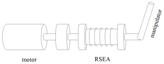
Figure 1.
Structure of space manipulator.
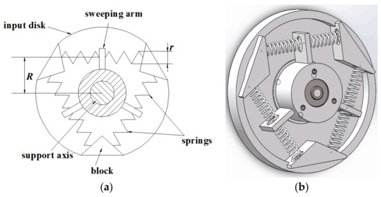
Figure 2.
Structure of the proposed rotary series elastic actuator. (a) Planar model. (b) Graphic model.
In the capture phase, the end-effector of the manipulator contacts and collides with the spacecraft, whereupon the joint of the manipulator will be subjected to a huge impact torque. The impact torque acts on the output sweeping arm of the RSEA device first, and then is transferred to the spring group. The impact energy generated by the collision is stored in the spring through the deformation of the spring group, so as to realize the protection of the joint. In the stable control phase, the joints are also affected by the impact torque due to the impact of the capture collision. If the torque exceeds the limit that the joint actuators can withstand and the actuators do not turn off, the actuators will be damaged. Therefore, it is necessary to set a shutdown torque threshold to turn off the actuators according to the torque limit that the joint can withstand. When the impact torque on the joints is detected to exceed the shutdown torque threshold value, all actuators turn off. In this time, the internal spring assembly of the RSEA device provides an elastic force to reduce the impact torque on the joints. In addition, in practical operation, if only the shutdown torque threshold is set, the actuators will be switched on and off frequently, thus affecting the actuators performance. On this basis, the control strategy proposed also sets a startup torque threshold value of actuators, when the joint torque exceeds the shutdown torque threshold, the actuators turn off, and when the joint torque is below the startup torque threshold, the actuators turn on again.
3. Dynamics Modeling and Impact Effect Analysis
The structure of a space robot with RSEA and target spacecraft systems is shown in Figure 3. The space robot consists of a rigid base B0, rigid links Bi (i = 1,2), and rigid target spacecraft B3. We build the inertial coordinate system XOY, while at the same time, the local coordinate system xiOiyi (i = 0,1,2) of each component Bi (i = 1,2) is established; O0 is the rotation center of the base, Oi is the rotation center of Bi (i = 1,2); m0 is the mass of the base, ms is the mass of the non-cooperative spacecraft, mi is the mass of Bi (i = 1,2). I0 is inertial moment of the base with respect to its mass center, Is is the inertial moment of the non-cooperative spacecraft with respect to its mass center, Ii (i = 1,2) is the inertial moment of Bi (i = 1,2) with respect to their mass center. I0 represents the distance from point O0 to O1, li (i = 1,2) represents length of Bi along the xi axis. di (i = 1,2) is the distance from the mass center of Bi to Oi. Iim (i = 1,2) is inertial moment of the i-h actuator. kim (i = 1,2) is the spring stiffness of the RSEA device. rc is the position vector of the mass center of the entire system in inertial coordinate system (XOY). ri (i = 1,2) is position vector of the mass center of Bi in the inertial coordinate system (XOY).
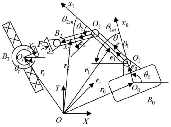
Figure 3.
Space robot with RSEA and target spacecraft systems.
Regarding the target spacecraft as a homogeneous rigid body, its dynamic equation can be obtained by the Newton-Euler method:
where the generalized coordinates of the target spacecraft system; , are the position vectors of the mass center of , is the attitude angle of the spacecraft system. are the inertia positive definite matrices, is its impact contact point corresponding to the motion Jacobi matrix. is the force acting on the spacecraft.
According to the position vector relation in Figure 2, the position vectors of the mass center of in the pre-contact phase are:
where , are the position vector of the mass center of base , is the unit vector along the xi axis in the frame.
Differentiating Equation (2) with respect to time t, then the total kinetic energy of the space robot with RSEA is:
where is the angular velocity of the rotation center , is the angular velocity of the actuator.
Neglecting the micro-gravity in space, the potential energy of the system only comes from the RSEA device, so the total potential energy of the system is:
where , , . is the deformation of the spring on the block of the RSEA device, is the angular difference between the sweeping arm and the input disk.
Based on Equations (3) and (4), and combing with the Lagrange equations, the dynamic equations of the space robot of pre-capture phase are as follows
where are the generalized coordinates of the system, is the attitude angle displacement of the base, is the attitude angle displacement of the i-th link, is the attitude angle displacement of the i-th actuator. are the inertia positive definite matrices, is the Coriolis/centrifugal matrix. , . , is the position control torque of the base, is the attitude control torque of base. is the joint torque/force delivered by actuators. , is the equivalent stiffness of joints, and its calculation formula is given in Equation (46). is its end-effector impact contact point corresponding motion Jacobi matrix, is the force acting on the end-effector.
In the capturing operation phase, the space robot contacts and collides with the target spacecraft, and the interaction force at the end is satisfied:
Based on Equation (6), and combining it with Equations (1) and (5), we can obtain that:
The actuators will be turned off during the capture phase, which is . Integrating Equation (7) over the momentary period of collision [13]:
The space robot and spacecraft satisfy the velocity constraint in the post-capture phase. Based on this, the following generalized velocity of the post-capture hybrid system can be obtained:
where .
Integrating first item of Equation (5), we have:
where is the impact impulse during the capture phase. Invoking Equations (9), and (10), we can obtain that:
where is the Moore-Penrose pseudo-inverse of . The period of contact is transient: , then the collision force can be approximated as:
After the space robot capturing the target spacecraft, a hybrid system is formed. Consider the velocity constraint relationship of arm and target, we can obtain that:
Differentiating Equation (13), we have:
Invoking Equations (1), (5) and (14), we can obtain that:
where ; .
In order to facilitate the design of subsequent control strategies, the first item of Equation (15) of the hybrid system can be expressed in the form of block matrices as follows, so as to obtain the fully controllable formal dynamics model:
where , , . , , , the submatrices of , , , , the submatrices of , and , are zero matrix. Equation (16) can be decomposed into:
From Equation (17), we have:
Invoking Equations (18) and (19), we can obtain that:
where , . And is an antisymmetric matrix.
4. Two-Time Scale Control
4.1. Fast Subsystem and the Corresponding Controller
In order to actively suppress the flexible vibration of the joint caused by the RSEA device, based on singular perturbation theory, the post-capture hybrid system was transformed into two subsystems, a slow rigid motion subsystem, and a fast flexible-joint subsystem. This controller consists of a slow sub-controller and a fast flexible-joint sub-controller:
where is the fast flexible-joint sub-controller, is the slow sub-controller.
Defining the positive proportional factor and the positive definite diagonal matrix , it satisfies:
Invoking Equation (22), the flexible-joint fast subsystem is:
In order to suppress the elastic vibration of the system, the following speed difference feedback controller is designed to control the fast subsystem:
where , is a positive definite diagonal matrix.
Substituting Equations (21), (24) into Equation (23), we have:
It can be shown that while , the equivalent stiffness of joints . At this point, the hybrid system is equivalent to a rigid model. Then the dynamic equation of the slow subsystem can be obtained from first item of Equations (20) and (21)
where , . is the corresponding matrix of when , .
4.2. Slow Subsystem and the Corresponding Controller
The buffer compliance control based on reinforcement learning is shown in Figure 4, Where ASN is used to approximate the unknown nonlinear term of the system, ACN is used to construct reinforcement signals to optimize ASN.
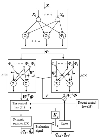
Figure 4.
The buffer compliance control block diagram based on Reinforcement Learning.
Define the trajectory tracking error as:
where are desired trajectories of the hybrid system.
At the same time, the error evaluation signal is defined as:
where is a positive definite diagonal matrix.
Invoking Equations (27) and (28), the dynamic equation of the slow subsystem can be written as:
where is the unknown nonlinear term of the system. Considering that it cannot be obtained directly, it can be approximated by the ASN:
where is the ideal weight matrix of a radial basis function neural network (RBFNN), is the optimal approximation error. The radial basis kernel functions are represented by a Gaussian radial basis function (GRBF) as:
where , and are the variance and the centre vector of the GRBF.
On this basis, the slow rigid motion subsystem control law is given as:
where is the estimate of the ideal weight . Defining the estimation error , it satisfies . is a positive definite diagonal matrix. is a robust control law, which is defined as:
where is a positive definite diagonal matrix.
Substituting Equations (32) and (33) into Equation (29), we have:
In order to optimize ASN, reinforcement learning signals are defined by CAN:
where is the estimate of the ideal weight .
Assumption 1.
The ideal weights , are bounded and satisfy:
where, is an unknown positive constant.
Assumption 2.
The optimal approximation error is bounded and satisfies:
whereis an unknown positive constant.
Next, the weight adaptive law of neural network can be further designed as:
where , are positive definite diagonal matrix. is a positive constant. Defining estimation error as , and it satisfied .
Theorem 1.
For the dynamic equation of the slow subsystem (26) with unknown nonlinear terms, supposing that Assumptions 1 and 2 hold and adopting the weight adaptive law (36) and (37), the control law (32) based on reinforcement learning signals (35) can ensure that the trajectory tracking errorconverges to zero asymptotically.
Proof of Theorem 1.
Introducing the Lyapunov function:
Differentiating Equation (13), we have:
Substituting Equations (34)–(37) into Equation (39) yields:
Combining Assumption 1, we have:
and combing Assumption 2, Equation (40) is rewritten as:
Considering the regression vector is bounded, it can be set . is minimum eigenvalue of . Equation (41) satisfies:
where , . To assure , we only require one of the following conditions:
Based on the analysis results of the above steps, and combing with the Lyapunov stability theorem, which implies that the whole closed-loop system is stable the trajectory tracking error converges to zero asymptotically from the stability analysis in Theorem 1. The proof is thus completed. □
5. Simulation Results
5.1. Impact Resistance Performance Simulation in the Capture Phase
To show the performance of the proposed controller, simulations are carried out on a planar space robot with the RSEA and target spacecraft systems shown in Figure 3. The actual parameters of the system are as follows: , , , ; , , , , , ; ; , , .
The equivalent stiffness of joints [30] is as follows:
where , , . is the angle of sweeping arm when the force acting on the end of the space manipulator, select .
In order to verify impact resistance performance simulation in the capture phase, the space robot system with/without RSEA device was used to carry out acquisition simulation tests on spacecraft with different velocity. The simulation results are shown in Table 1.

Table 1.
RSEA impact resistance at different initial velocities of spacecraft.
In Table 1, the first column of velocity terms, the first two are linear velocities, and the third is angular velocities. In the second and third columns, the preceding and the following items are the impact torques of joints without and with RSEA devices respectively. The fourth column has the maximum percentage reduction in joint impact torque with the RSEA device. As can be seen from Table 1, for the capture phase of spacecraft at different initial velocities, the configuration of RSEA device can effectively reduce the impact torque acting on joints, and effectively realize the protection of the joint.
5.2. Buffer Compliance Control Performance Simulation in Stable Control Phase
To show the buffer compliance control performance of the proposed controller, simulations are carried out for stable control phase. The actual parameters of the system are as follows: K2 = diag(5,5), Λ = diag(5,5,5), Kz = diag(400,400,400), ε = 0.5, Ka = diag(20,20,20), Kb = diag(50,50,50), η = 1, Kc = diag(10,10,10). In pre-impact phase , assuming that the space robot system capturing a non-cooperative spacecraft at . At this time, the velocity of the spacecraft is , the desired trajectory of post-capture hybrid system is . Assume that when the joint actuators running, the limit of the impact torque it can bear is . In order to protect the joint actuators, the buffer compliance control strategy of active opening and closing actuators (named switching strategy) is adopted. The shutdown torque threshold is , and the startup torque threshold is . The simulation results are shown in Figure 5, Figure 6, Figure 7, Figure 8, Figure 9 and Figure 10.
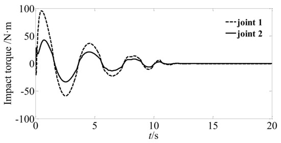
Figure 5.
Joints’ impact torque without switching strategy.

Figure 6.
Joints’ impact torque with switching strategy.
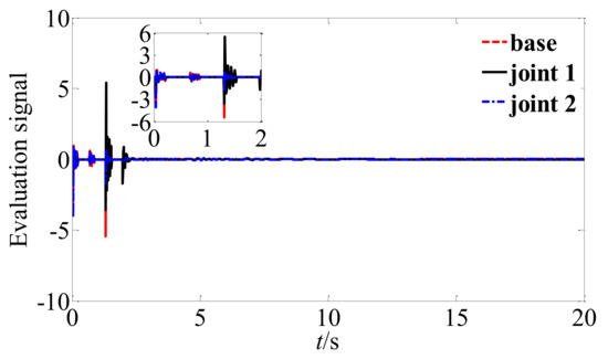
Figure 7.
The evaluation signal.
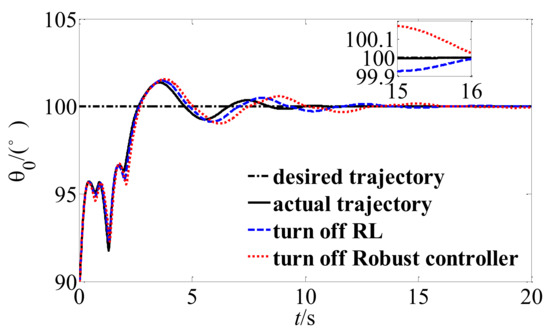
Figure 8.
Trajectory tracking of base attitude.
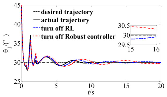
Figure 9.
Trajectory tracking of joint angle 1.
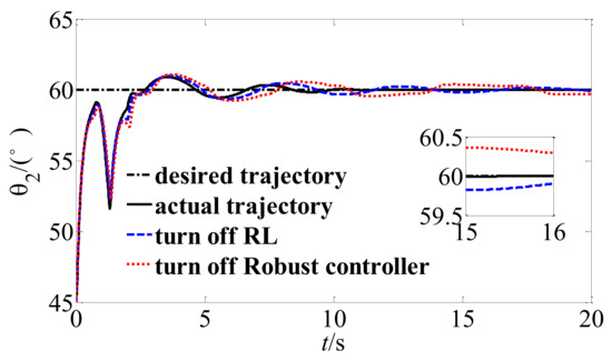
Figure 10.
Trajectory tracking of joint angle 2.
Figure 5 shows the impact torque acting on the joints when not adopting the switching strategy, where it can be found that the impact torque still exceeds the safety threshold of the joint at this time. Figure 6 shows the impact torque acting on the joints when adopting a switching strategy. By comparing Figure 5 and Figure 6, it can be seen that the impact torque acting on the joints can be limited within a safe range by combining with the buffer compliance control, which ensures the protection of the joint motor during the stable control phase. Figure 7 shows the evaluation factor signal. It can be found that the ACN is optimized through the interaction with the environment and the reward signal is obtained, and finally reaches the stable state.
To show the effectiveness of the defined reinforcement signal, the tracking accuracy is quantitatively analyzed by comparison of the trajectory tracking error of the proposed RL control scheme, RL with robust controller off and neural network control strategy without reinforcement signal (turn off RL). The mean absolute error MAE = was used to evaluate the tracking accuracy, the simulation results are shown in Table 2. It can be seen in Table 2 the mean absolute error of proposed RL is smaller than the other control strategies, which shown that the proposed control method has high tracking accuracy and good tracking performance.

Table 2.
The mean absolute error of trajectory tracking.
Figure 8, Figure 9 and Figure 10 shows the stabilization of the hybrid system when the proposed buffer compliance controller is adopted. The solid line is the trajectory tracking curve of the system when the control algorithm based on reinforcement learning is adopted, the dotted line is the trajectory tracking curve when turn off the robust term , the double line is the trajectory tracking curve when turn off RL. By comparing them, it can be found that the unstable hybrid system finally reaches the stable and expected state, and the proposed RL control scheme has faster convergence speed and higher tracking accuracy.
If the fast subsystem controller of the system is turned off, the system trajectory tracking curve shown in Figure 11, Figure 12 and Figure 13 can be obtained. By comparing Figure 8, Figure 9 and Figure 10 with Figure 11, Figure 12 and Figure 13, it can be seen that if the fast subsystem is turned off, the elastic vibration of the unstable hybrid system will continue to increase and eventually lead to the divergence of the system. Therefore, the proposed velocity difference feedback controller can actively suppress the elastic vibration of the system joint, and then achieve stable track of the trajectory.
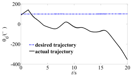
Figure 11.
Trajectory of the base attitude without a fast controller.
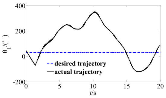
Figure 12.
Trajectory of the joint angle 1 without a fast controller.
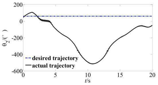
Figure 13.
Trajectory of the joint angle 2 without a fast controller.
6. Conclusions
In this paper a space robot with a RSEA device to protect the joint of the robot under impact torque during the satellite capture process is designed. The timely opening and closing of joint actuators was proposed to achieve buffer compliance control. The dynamic model of the post-capture hybrid system was derived from the Lagrange equations, law of conservation of momentum and the constraints of kinematics and velocity. Then, based on singular perturbation theory, the hybrid system was decomposed into a slow subsystem and a fast subsystem. A buffer compliance control based on a reinforcement learning algorithm was applied to control the slow subsystem with unknown unknown nonlinear disturbances term. The fast control was designed with speed difference feedback controller. The simulation results show that the proposed strategy can reduce the impact torque by 76.6% at the maximum and 58.7% at the minimum during the capture phase, which reflects a good anti-impact performance. In the stable control phase, the impact torque acting on the joint is guaranteed to be limited within the safety threshold, so as to avoid the overload and damage of the joint actuators. In addition, the proposed reinforcement learning strategy has strong online adaptability and autonomous learning ability under complex conditions and can be continuously optimized through real-time interaction with the complex space environment, so as to ensure the accuracy and stability of the system stabilization motion.
Note that this paper only considers that space manipulators mounted on their spacecraft are rigid. For future research, the buffer compliance control of space robot with a flexible-link capturing a non-cooperative spacecraft control problem will be studied, and the control scheme extended to practical applications.
Author Contributions
Conceptualization, H.A.; methodology, H.A. and X.Y.; software A.Z. and J.W.; investigation, H.A. and A.Z.; writing original-draft preparation, H.A.; writing—review and editing, H.A. and X.Y.; supervision, H.A. and L.C.; funding acquisition, H.A. and X.Y. All authors have read and agreed to the published version of the manuscript.
Funding
This work was supported by the National Natural Science Foundation of China (Grant No. 51741502, 11372073), Science and Technology Project of the Education Department of Jiangxi Province (Grant No. GJJ200864), Jiangxi University of Science and Technology PhD Research Initiation Fund (Grant No. 205200100514).
Informed Consent Statement
Informed consent was obtained from all subjects involved in the study.
Conflicts of Interest
The authors declare no conflict of interest.
References
- Flores-Abad, A.; Ma, O.; Pham, K.; Ulrich, S. A review of space robotics technologies for on-orbit servicing. Prog. Aerosp. Sci. 2014, 68, 1–26. [Google Scholar] [CrossRef]
- Yu, X.; Chen, L. Observer-based two-time scale robust control of free-flying flexible-joint space manipulators with external disturbances. Robotica 2017, 35, 2201–2217. [Google Scholar] [CrossRef]
- Meng, Q.L.; Liang, J.X.; Ma, O. Identification of all the inertial parameters of a non-cooperative object in orbit. Aerosp. Sci. Technol. 2019, 91, 571–582. [Google Scholar] [CrossRef]
- Boning, P.; Dubosky, S. A kinematic approach to determining the optimal actuator sensor architecture for space robots. Int. J. Robot. Res. 2011, 30, 1194–1204. [Google Scholar] [CrossRef][Green Version]
- Giordano, A.M.; Ott, C.; Albu, A. Coordinated control of spacecraft’s attitude and end-effector for space robots. IEEE Robot. Autom. Lett. 2019, 4, 2108–2115. [Google Scholar] [CrossRef]
- Qin, L.; Liu, F.C.; Liang, L.H.; Gao, J.F. Fuzzy adaptive robust control for space robot considering the effect of the gravity. Chin. J. Aeronaut. 2014, 27, 1562–1570. [Google Scholar] [CrossRef][Green Version]
- Virgili-Llop, J.; Zagaris, C.; Zappulla, I.R.; Bradstreet, A.; Romano, M. A convex-programming-based guidance algorithm to capture a tumbling object on orbit using a spacecraft equipped with a robotic manipulator. Int. J. Robot. Res. 2019, 38, 40–72. [Google Scholar] [CrossRef]
- Ai, H.P.; Chen, L. Force/position fuzzy control of space robot capturing spacecraft by dual-arm clamping. J. Harbin Eng. Univ. 2020, 41, 1847–1853. [Google Scholar]
- Liu, X.; Li, H.; Wang, J.; Cai, G. Dynamics analysis of flexible space robot with joint friction. Aerosp. Sci. Technol. 2015, 47, 164–176. [Google Scholar] [CrossRef]
- Lim, J.; Chung, J. Dynamic analysis of a tethered satellite system for space debris capture. Nonlinear Dyn. 2018, 94, 1–18. [Google Scholar] [CrossRef]
- Shah, S.V.; Sharf, I.; Misra, A. Reactionless path planning strategies for capture of tumbling objects in space using a dual-arm robotic system. In Proceedings of the AIAA Guidance, Navigation, and Control Conference, Boston, MA, USA, 15 August 2013; p. 4521. [Google Scholar]
- Uyama, N.; Hirano, D.; Nakanishi, H.; Nagaoka, K.; Yoshida, K. Impedance-based contact control of a free-flying space robot with respect to coefficient of restitution. In Proceedings of the IEEE/SICE International Symposium on System Integration, Kyoto, Japan, 9 February 2012; pp. 1196–1201. [Google Scholar]
- Jing, C.; Li, C. Mechanical analysis and calm control of dual-arm space robot for capturing a satellite. Chin. J. Theor. Appl. Mech. 2016, 48, 832–842. (In Chinese) [Google Scholar]
- Jiang, B.; Hu, Q.; Friswell, M.I. Fixed-time attitude control for rigid spacecraft with actuator saturation and faults. IEEE Trans. Control Syst. Technol. 2016, 24, 1892–1898. [Google Scholar] [CrossRef]
- Liu, S.P.; Wu, L.C.; Lu, Z. Impact dynamics and control of a flexible dual-arm space robot capturing an object. Appl. Math. Comput. 2007, 185, 1149–1159. [Google Scholar] [CrossRef]
- Walker, M.W.; Wee, L.-B. Adaptive control of space-based robot manipulators. IEEE Trans. Robot. Autom. 1991, 7, 828–835. [Google Scholar] [CrossRef][Green Version]
- Yi, Z.G.; Ge, X.S. Attitude motion trajectory tracking for underactuated spacecraft based on indirect legendre pesudospectral method. J. Astronaut. 2018, 39, 648–655. (In Chinese) [Google Scholar]
- Sands, T. Optimization Provenance of Whiplash Compensation for Flexible Space Robotics. Aerospace 2019, 6, 93. [Google Scholar] [CrossRef]
- Stolfi, A.; Gasbarri, P.; Sabatini, M. A combined impedance-PD approach for controlling a dual-arm space manipulator in the capture of a non-cooperative target. Acta Astronaut. 2017, 139, 243–253. [Google Scholar] [CrossRef]
- Zhang, H.W.; Zhu, Z.X. Sampling-Based Motion Planning for Free-Floating Space Robot without Inverse Kinematics. Appl. Sci. 2020, 10, 9137. [Google Scholar] [CrossRef]
- Cocuzza, S.; Pretto, I.; Debei, S. Least-Squares-Based Reaction Control of Space Manipulators. J. Guid. Control Dyn. 2012, 35, 976–986. [Google Scholar] [CrossRef]
- Du, H.; Li, S.; Qian, C. Finite-Time Attitude Tracking Control of Spacecraft with Application to Attitude Synchronization. IEEE Trans. Autom. Control 2011, 56, 2711–2717. [Google Scholar] [CrossRef]
- Aghili, F. A prediction and motion-planning scheme for visually guided robotic capturing of free-floating tumbling objects with uncertain dynamics. IEEE Trans. Robot. 2012, 28, 634–649. [Google Scholar] [CrossRef]
- Yu, X. Hybrid-Trajectory Based Terminal Sliding Mode Control of a Flexible Space Manipulator with an Elastic Base. Robotica 2019, 38, 550–563. [Google Scholar] [CrossRef]
- Cheng, J.; Chen, L. Elm neural network control of attitude management and auxiliary docking maneuver after dual-arm space robot capturing spacecraft. Robotica 2017, 39, 724–732. (In Chinese) [Google Scholar]
- Wang, M.; Luo, J.; Yuan, J.; Walter, U. An integrated control scheme for space robot after capturing non-cooperative target. Acta Astronaut. 2018, 147, 350–363. [Google Scholar] [CrossRef]
- Zhang, B.; Liang, B.; Wang, Z.; Mi, Y.; Zhang, Y.; Chen, Z. Coordinated stabilization for space robot after capturing a noncooperative target with large inertia. Acta Astronaut. 2017, 134, 75–84. [Google Scholar] [CrossRef]
- Wu, S.; Mou, F.; Liu, Q.; Cheng, J. Contact dynamics and control of a space robot capturing a tumbling object. Acta Astronaut. 2018, 151, 532–542. [Google Scholar] [CrossRef]
- Rekleitis, G.; Papadopoulos, E. On-orbit cooperating space robotic servicers handling a passive object. IEEE Trans. Aerosp. Electron. Syst. 2015, 51, 802–814. [Google Scholar] [CrossRef]
- Gu, X.; Wang, K.; Cheng, T.; Zhang, X. Mechanical design of a 3-DOF humanoid soft arm based on modularized series elastic actuator. In Proceedings of the IEEE International Conference on Mechatronics and Automation, Beijing, China, 3 September 2015; pp. 1127–1131. [Google Scholar]
- Calanca, A.; Fiorini, P. Understanding environment-adaptive force control of series elastic actuators. IEEE ASME Trans. Mechatron. 2018, 23, 413–423. [Google Scholar] [CrossRef]
- Wang, M.; Sun, L.; Yin, W.; Dong, S.; Liu, J. Nonlinear disturbance observer based torque control for series elastic actuator. In Proceedings of the IEEE/RSJ International Conference on Intelligent Robots and Systems, Daejeon, Korea, 1 December 2016; pp. 286–291. [Google Scholar]
- Liu, S.; Wu, S.; Liu, Y.; Wu, Z.G.; Mao, Z.M. Autonomous reinforcement learning control for space robot to capture non-cooperative targets. Sci. Sin. Phys. Mech. Astron. 2019, 49, 113–122. [Google Scholar] [CrossRef]
- Sands, T. Development of Deterministic Artificial Intelligence for Unmanned Underwater Vehicles (UUV). J. Mar. Sci. Eng. 2020, 8, 578. [Google Scholar] [CrossRef]
- Tang, L.; Liu, Y.J. Adaptive neural network control of robot manipulator using reinforcement learning. J. Vib. Control 2014, 20, 2162–2171. [Google Scholar] [CrossRef]
- Cui, R.; Yang, C.; Li, Y.; Sharma, S. Adaptive Neural Network Control of AUVs With Control Input Nonlinearities Using Reinforcement Learning. IEEE Trans. Syst. Man Cybern. Syst. 2017, 47, 1019–1029. [Google Scholar] [CrossRef]
Publisher’s Note: MDPI stays neutral with regard to jurisdictional claims in published maps and institutional affiliations. |
© 2021 by the authors. Licensee MDPI, Basel, Switzerland. This article is an open access article distributed under the terms and conditions of the Creative Commons Attribution (CC BY) license (https://creativecommons.org/licenses/by/4.0/).