
A Robot-Centered Path-Planning Algorithm for Multidirectional Additive Manufacturing for WAAM Processes and Pure Object Manipulation

 , , , , and
Abstract
:1. Introduction
2. Multidirectional Additive Manufacturing
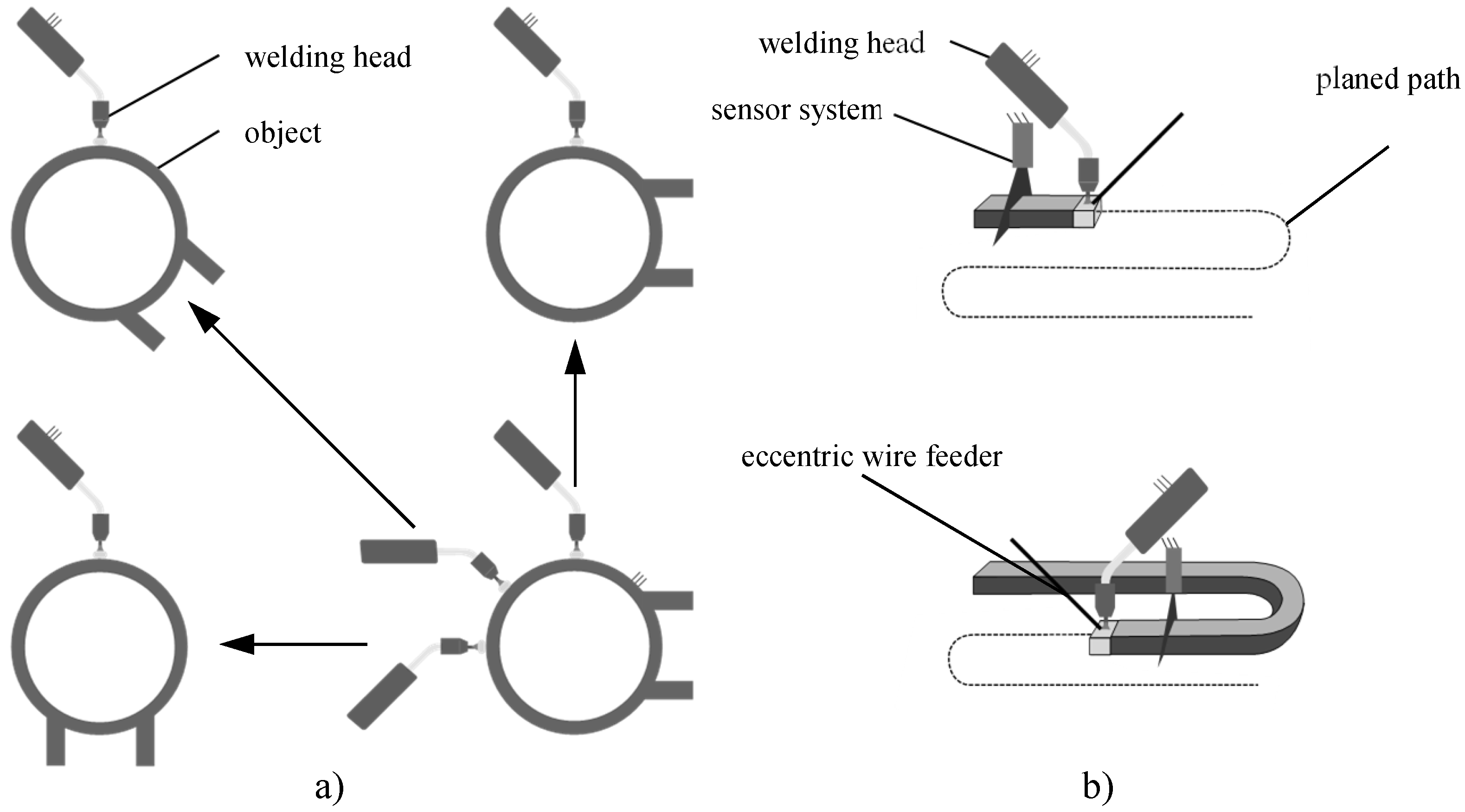
2.1. General Concept
- A wire feed must mainly be fed from the front, or at least from a defined direction in relation to the direction of movement, because the geometry of the deposited material is highly dependent on the relative alignment of the wire.
- Sensors used for monitoring and controlling the process should continuously analyze the weld seam and must therefore always be aligned with the welding process.
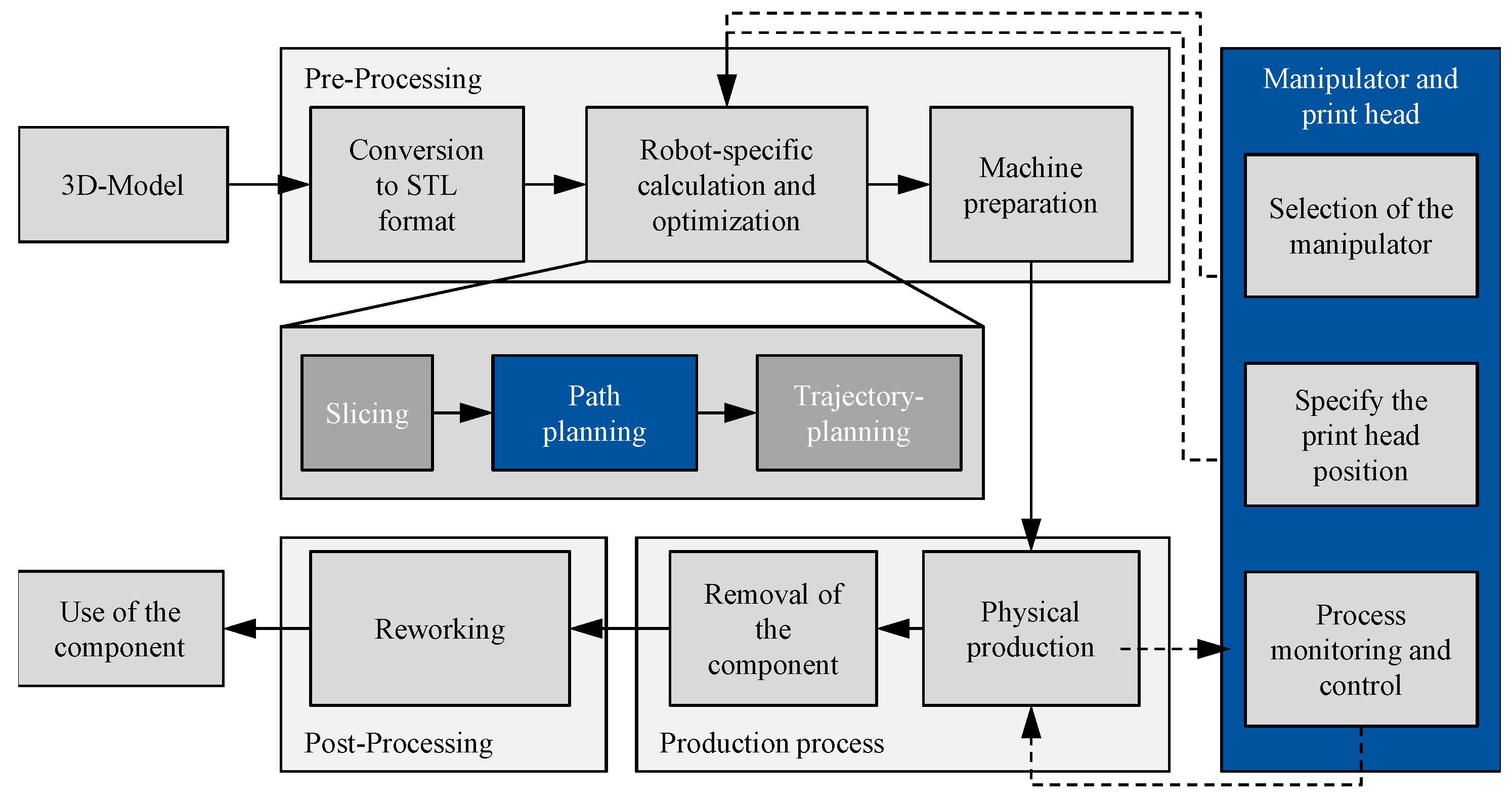
2.2. Process Chain
2.3. Major Challenges
3. Path Planning in Robotics and Additive Manufacturing
3.1. Path Planning in Additive Manufacturing
3.2. Path Planning in Robotics
3.3. Requirements on New Path Planning Algorithm
- Process slices in any spatial orientation.
- Consideration of robot kinematics, joint limits and corresponding assurance of feasibility.
- Geometrical outward approximation of the cross-section.
- Search for the best possible overall path based on defined criteria (from robotics and welding process).
- Minimize calculation time.
- Cover the entire slice without gaps.
- Include path elements that favor continuous and uniform trajectory execution by the robot.
- Modular implementation (extensibility and interchangeability of components).
4. Concept of Manipulator-Specific Path Planning
5. Methods and Algorithms
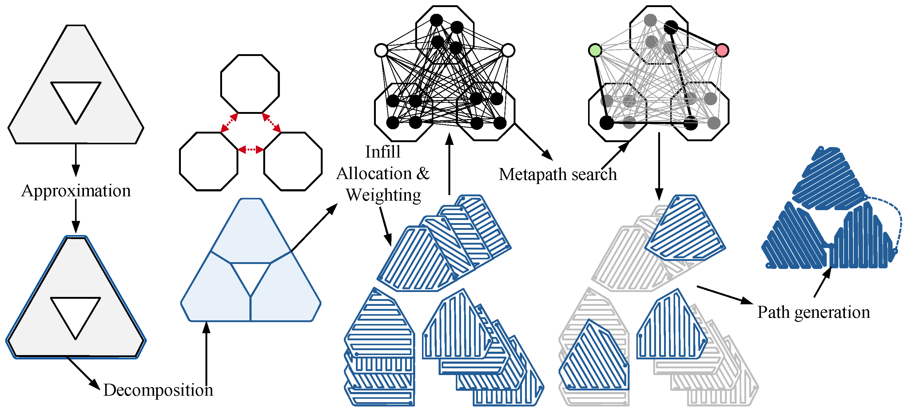
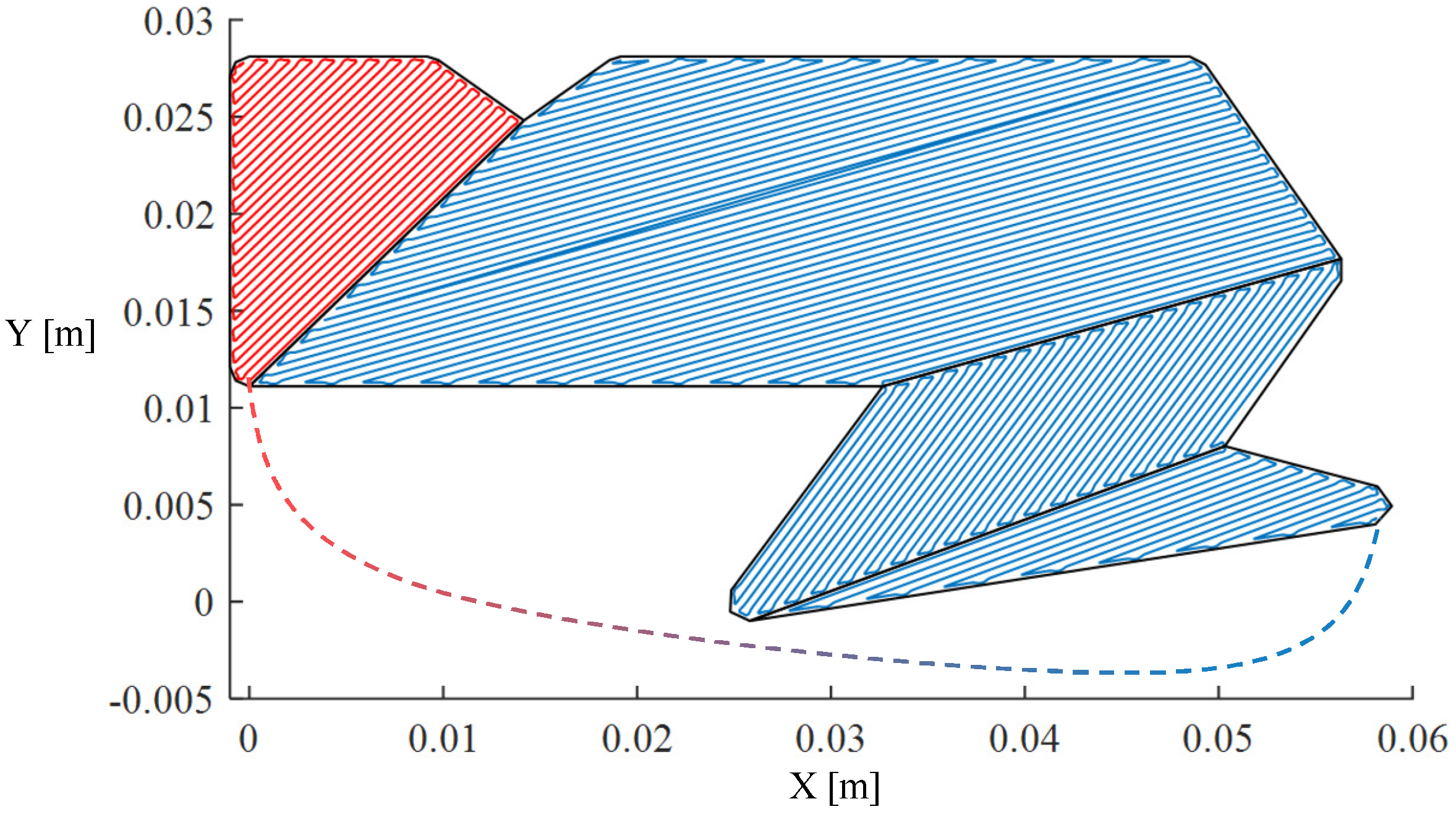
5.1. Slice Decomposition
- Identify external (outer contour) and internal (holes) polygons.
- Sort the vertices of external polygons clockwise and the vertices of internal polygons counter-clockwise.
- Calculate the angles between the incoming and outgoing edges of each polygon vertex .
- Identify notches. A notch is defined as a vertex whose associated angle from the previous step is greater than 0. A polygon with at least one notch is not convex.
- Eliminate notches.
- Notch-line () decomposition, see ;
- Notch-vertex () decomposition, see ; and
- Notch-notch () decomposition, see .
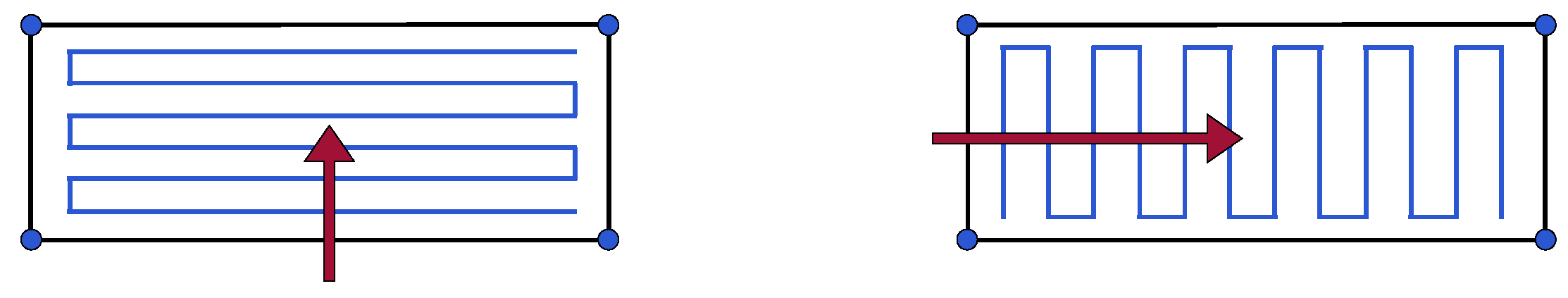
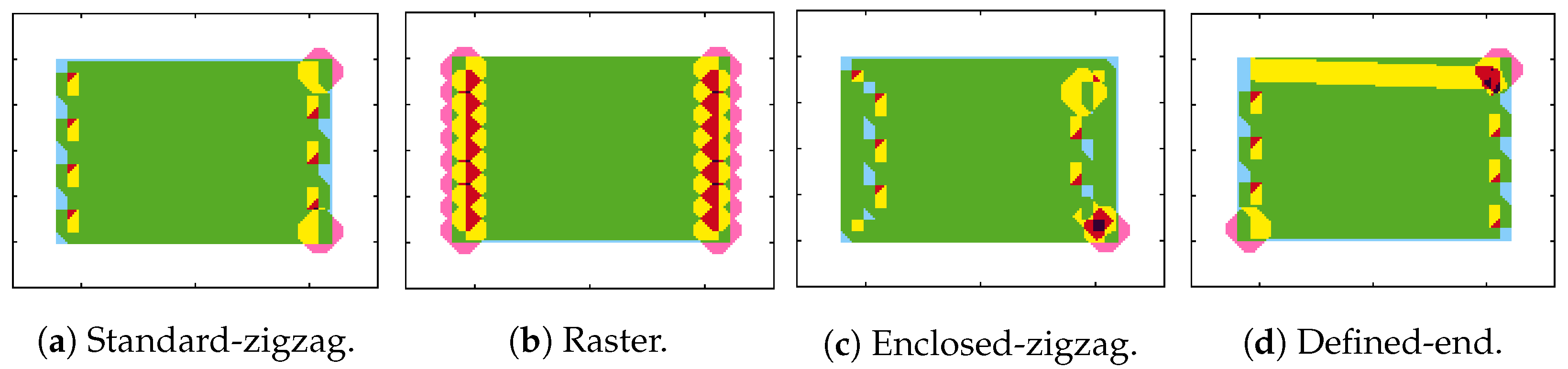
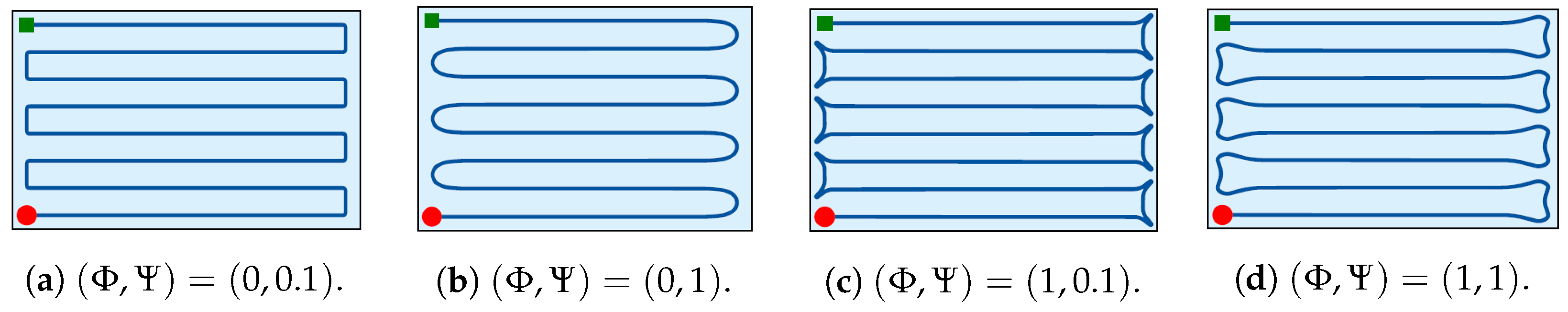
5.2. Infill Strategies
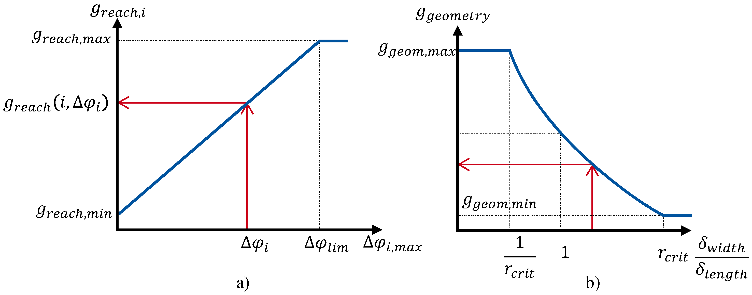
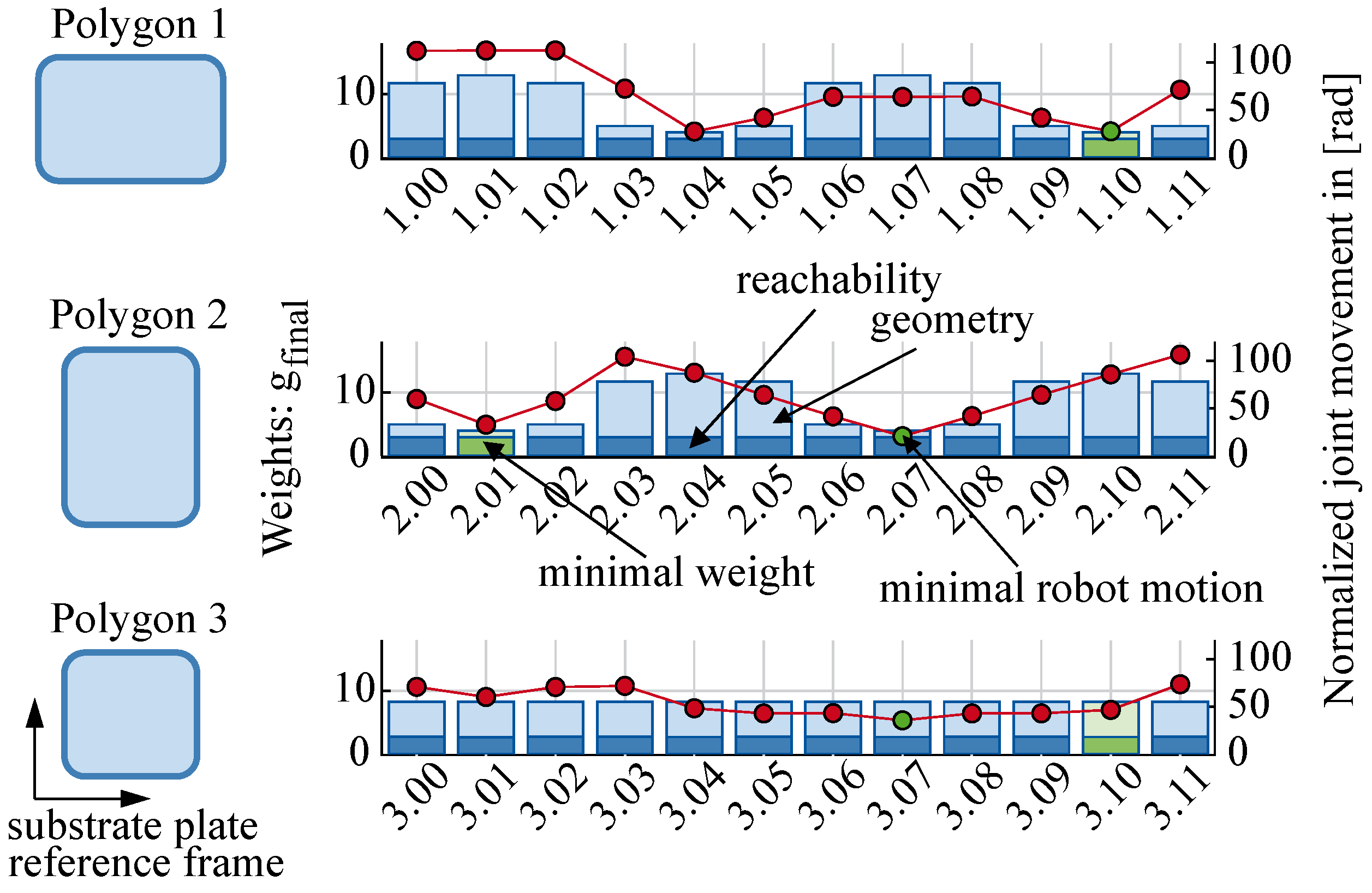
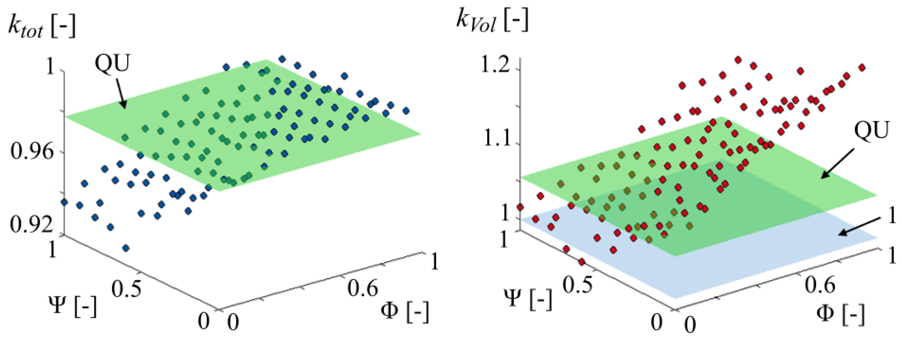
5.3. Infill Strategy Weighting
- The x-axis corresponds to the main infill direction to be analyzed.
- The z-axis corresponds to the layer normal vector.
- The y-axis completes the right-handed coordinate system.
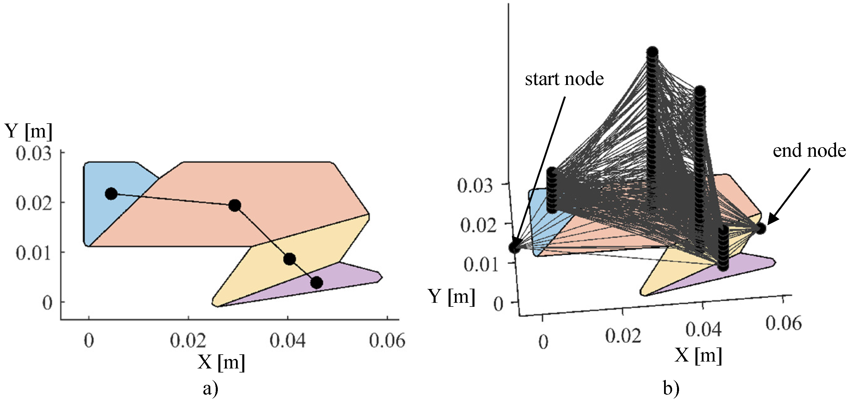
5.4. Meta Path Search
5.5. Path Planning and Trajectory-Pre-Processing
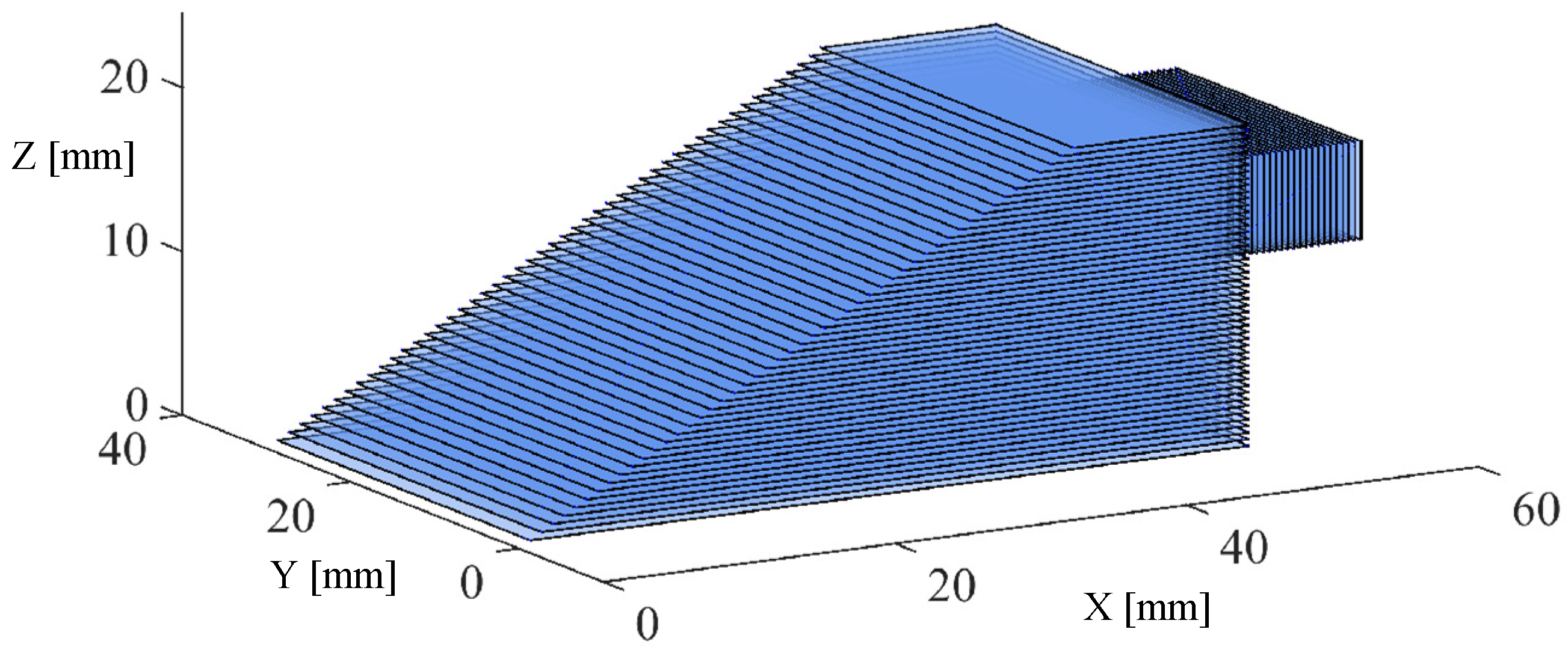
6. Results
6.1. Analysis of Manipulability Weighted Graph Search
6.2. Analysis of Path Smoothing
7. Discussion
Author Contributions
Funding
Informed Consent Statement
Data Availability Statement
Acknowledgments
Conflicts of Interest
References
- Reisgen, U.; Sharma, R.; Oster, L. Plasma multiwire technology with alternating wire feed for tailor-made material properties in wire and arc additive manufacturing. Metals 2019, 9, 745. [Google Scholar] [CrossRef] [Green Version]
- Detert, T.; Lorenz, M.; Schmitz, M.; Hüsing, M.; Corves, B. Robotergeführte Objektmanipulation für die generative Fertigung. IFToMM Tagungsband 2017. [Google Scholar] [CrossRef]
- Ding, D.; Pan, Z.; Cuiuri, D.; Li, H.; Larkin, N.; van Duin, S. Multi-direction slicing of STL models for robotic wire-feed additive manufacturing. In Solid Freeform Fabrication Symposium; The University of Texas at Austin: Austin, TX, USA, 2015; pp. 1059–1069. Available online: http://utw10945.utweb.utexas.edu/sites/default/files/2015/2015-88-Ding.pdf (accessed on 20 June 2021).
- Corves, B.; Hüsing, M.; Bezrucav, S.; Detert, T.; Lauwigi, J.; Lorenz, M.; Mandischer, N.; Schmitz, M.; Shahidi, A. Robotik 4.0. In Handbuch Industrie 4.0: Recht, Technik, Gesellschaft; Springer: Berlin/Heidelberg, Germany, 2020; pp. 569–589. ISBN 978-3-662-58474-3. [Google Scholar]
- Schmitz, M.; Weidemann, C.; Corves, B.; Hüsing, M. Trajectory Planning Strategy for Multidirectional Wire-Arc Additive Manufacturing. In ROMANSY 23—Robot Design, Dynamics and Control; Springer: Berlin/Heidelberg, Germany, 2020; pp. 467–475. [Google Scholar] [CrossRef]
- Schmitz, M.; Corves, B.; Hüsing, M. Multidirektionale Additive Fertigung: Motivation, Problemstellung und Strategien im Kontext des Schweißens mit Drahtzuführung. In Proceedings of the Sixth IFToMM D-A-CH Conference 2020, Lienz, Austria, 27–28 February 2020. [Google Scholar] [CrossRef]
- Zhang, G.Q.; Mondesir, W.; Martinez, C.; Li, X.; Fuhlbrigge, T.A.; Bheda, H. Robotic additive manufacturing along curved surface—A step towards free-form fabrication. In Proceedings of the 2015 IEEE International Conference on Robotics and Biomimetics (ROBIO), Zhuhai, China, 6–9 December 2015; pp. 721–726. [Google Scholar]
- Fang, H.; Ong, S.; Nee, A. Robot path planning optimization for welding complex joints. Int. J. Adv. Manuf. Technol. 2017, 90, 3829–3839. [Google Scholar] [CrossRef]
- Technikmensch. Simplify3D—Alles über den Premium-Slicer für den 3D-Druck. 2019. Available online: https://technikmensch.de/simplify-3d/ (accessed on 20 June 2021).
- Dunlavey, M.R. Efficient polygon-filling algorithms for raster displays. ACM Trans. Graph. (Tog) 1983, 2, 264–273. [Google Scholar] [CrossRef]
- Park, S.C.; Choi, B.K. Tool-path planning for direction-parallel area milling. Comput.-Aided Des. 2000, 32, 17–25. [Google Scholar] [CrossRef]
- Huang, W.H. Optimal line-sweep-based decompositions for coverage algorithms. In Proceedings of the 2001 ICRA. IEEE International Conference on Robotics and Automation (Cat. No. 01CH37164), Seoul, Korea, 21–26 May 2001; Volume 1, pp. 27–32. [Google Scholar]
- Farouki, R.; Koenig, T.; Tarabanis, K.; Korein, J.; Batchelder, J. Path planning with offset curves for layered fabrication processes. J. Manuf. Syst. 1995, 14, 355–368. [Google Scholar] [CrossRef]
- Wang, H.; Stori, J.A. A metric-based approach to 2D tool-path optimization for high-speed machining. In Proceedings of the 2002 ASME International Mechanical Engineering Congress and Exposition, New Orleans, LA, USA, 17–22 November 2002; Volume 3641, pp. 139–148. [Google Scholar]
- Zhang, J.; Liou, F. Adaptive slicing for a multi-axis laser aided manufacturing process. J. Mech. Des. 2004, 126, 254–261. [Google Scholar] [CrossRef]
- Jin, G.; Li, W.D.; Gao, L. An adaptive process planning approach of rapid prototyping and manufacturing. Robot. Comput.-Integr. Manuf. 2013, 29, 23–38. [Google Scholar] [CrossRef]
- Bertoldi, M.; Yardimci, M.; Pistor, C.; Guceri, S. Domain decomposition and space filling curves in toolpath planning and generation. In 1998 International Solid Freeform Fabrication Symposium; The University of Texas in Austin: Austin, TX, USA, 1998. [Google Scholar]
- Ding, D.; Pan, Z.; Cuiuri, D.; Li, H. Wire-feed additive manufacturing of metal components: Technologies, developments and future interests. Int. J. Adv. Manuf. Technol. 2015, 81, 465–481. [Google Scholar] [CrossRef]
- Wasser, T.; Jayal, A.D.; Pistor, C. Implementation and evaluation of novel buildstyles in fused deposition modeling (FDM). In 1999 International Solid Freeform Fabrication Symposium; The University of Texas at Austin: Austin, TX, USA, 1999. [Google Scholar]
- Dwivedi, R.; Kovacevic, R. Process planning for multi-directional laser-based direct metal deposition. Proc. Inst. Mech. Eng. Part C J. Mech. Eng. Sci. 2005, 219, 695–707. [Google Scholar] [CrossRef]
- Ding, D.; Pan, Z.S.; Cuiuri, D.; Li, H. A tool-path generation strategy for wire and arc additive manufacturing. Int. J. Adv. Manuf. Technol. 2014, 73, 173–183. [Google Scholar] [CrossRef] [Green Version]
- Lin, S.; Xia, L.; Ma, G.; Zhou, S.; Xie, Y.M. A maze-like path generation scheme for fused deposition modeling. Int. J. Adv. Manuf. Technol. 2019, 104, 1509–1519. [Google Scholar] [CrossRef]
- Webpage of Simplify3d. Available online: https://www.simplify3d.com/. (accessed on 20 June 2021).
- Biagiotti, L.; Melchiorri, C. Trajectory Planning for Automatic Machines and Robots; Springer Science & Business Media: Berlin/Heidelberg, Germany, 2008. [Google Scholar]
- Craig, J.J. Introduction to Robotics; Pearson Education International: London, UK, 2005. [Google Scholar]
- Atkar, P.N.; Greenfield, A.; Conner, D.C.; Choset, H.; Rizzi, A.A. Uniform coverage of automotive surface patches. Int. J. Robot. Res. 2005, 24, 883–898. [Google Scholar] [CrossRef]
- Ding, D.; Pan, Z.; Cuiuri, D.; Li, H. A practical path planning methodology for wire and arc additive manufacturing of thin-walled structures. Robot. Comput.-Integr. Manuf. 2015, 34, 8–19. [Google Scholar] [CrossRef] [Green Version]
- Martina, F.; Mehnen, J.; Williams, S.W.; Colegrove, P.; Wang, F. Investigation of the benefits of plasma deposition for the additive layer manufacture of Ti–6Al–4V. J. Mater. Process. Technol. 2012, 212, 1377–1386. [Google Scholar] [CrossRef] [Green Version]
- Mehnen, J.; Ding, J.; Lockett, H.; Kazanas, P. Design for wire and arc additive layer manufacture. In Global Product Development; Springer: Berlin/Heidelberg, Germany, 2011; pp. 721–727. [Google Scholar]
- Livesu, M.; Ellero, S.; Martínez, J.; Lefebvre, S.; Attene, M. From 3D models to 3D prints: An overview of the processing pipeline. In Computer Graphics Forum; Wiley Online Library: Hoboken, NJ, USA, 2017; Volume 36, pp. 537–564. [Google Scholar]
- Keil, J.M. Polygon Decomposition. Handb. Comput. Geom. 2000, 2, 491–518. [Google Scholar]
- Corves, B.; Hüsing, M.; Wiartalla, J.; Schmitz, M. 7. IFToMM D-A-CH Konferenz 2021, 18./19. Februar 2021. Online-Konferenz. Manipulatorspezifische Pfadplanung für die Multidirektionale Additive Fertigung. Siebte IFToMM D-A-CH Konferenz 2021: 18./19. Februar 2021, Online-Konferenz 2021. Available online: https://doi.org/10.17185/duepublico/74042 (accessed on 20 June 2021).
- Reisgen, U.; Mann, S.; Oster, L.; Lozano, P.; Sharma, R. Study on Workpiece and Welding Torch Height Control for Polydirectional WAAM by Means of Image Processing. In Proceedings of the 2019 IEEE 15th International Conference on Automation Science and Engineering (CASE), Vancouver, BC, Canada, 22–26 August 2019; pp. 6–11. [Google Scholar] [CrossRef]
- Quigley, M.; Conley, K.; Gerkey, B.; Faust, J.; Foote, T.; Leibs, J.; Wheeler, R.; Ng, A.Y. ROS: An open-source Robot Operating System. In Proceedings of the ICRA Workshop on Open Source Software, Kobe, Japan, 12–17 May 2009; Volume 3, p. 5. Available online: http://www.cim.mcgill.ca/~dudek/417/Papers/quigley-icra2009-ros.pdf (accessed on 20 June 2021).
- Rahman, M.S.; Kaykobad, M.; Firoz, J.S. New sufficient conditions for Hamiltonian paths. In Proceedings of the 2012 IEEE 15th International Conference on Computer and Information Technology (ICCIT), Chittagong, Bangladesh, 22–24 December 2012; pp. 21–25. [Google Scholar]
- Farin, G.E.; Farin, G. Curves and Surfaces for CAGD: A Practical Guide; Morgan Kaufmann: Burlington, MA, USA, 2002. [Google Scholar]


| Reference | Relevant Developments | Advantages | Disadvantages |
|---|---|---|---|
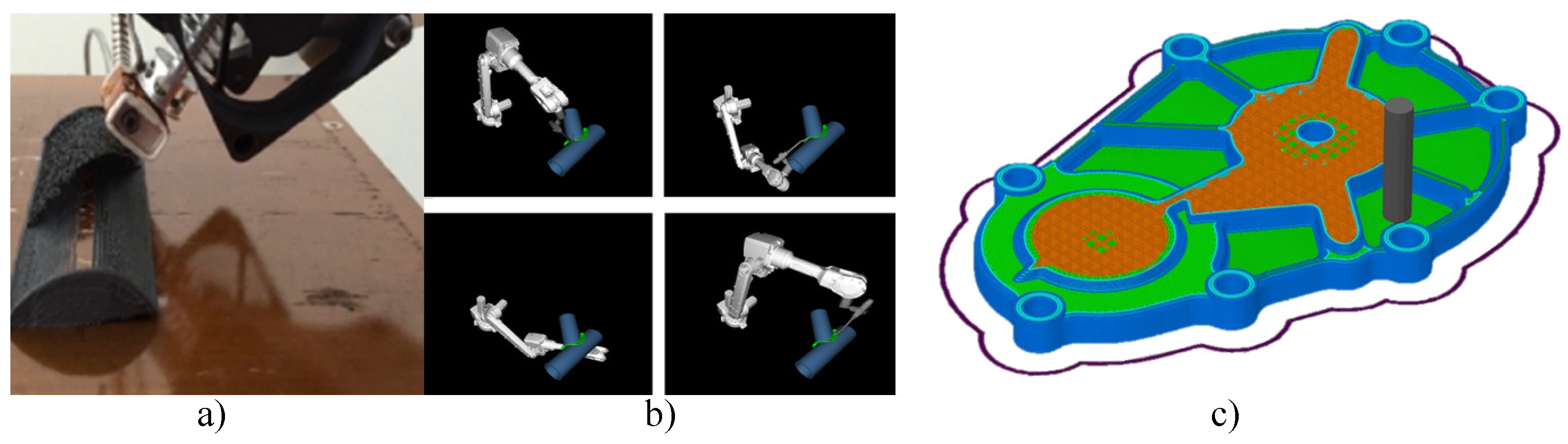
| Zhang et al. [7] | change of building direction and curves surfaces/slices (cf. Figure 5a) | necessary subvolumization approach | restricted range for building direction |
| Fang et al. [8] | segmented consideration of paths (cf. Figure 5b) | include process parameter into optimization, optimize robot motion | use of rotational degree of freedom around the welding head |
| Simplify3D [9] (cf. Figure 5c) | subdivision of objects to be printed into an outer shell and an infill structure | - | 2.5D Slicer without any optimization |
| Dunlavey et al. [10] | raster infill strategy | easy process handling | 2.5D Slicer |
| Park et al. [11] | zigzag infill strategy | continuous path, reduced number of sub-paths, fewer transition movements | many changes in printing direction |
| Huang [12] | dividing slices into many convex polygons, optimization algorithm generates optimal zigzag infill orientation | minimal number of changes in direction | - |
| Farouki et al. [13] | contour infill strategy (Figure 4) | reduce mistakes near the contour | orientation changes more then 180 deg |
| Wang et al. [14] | spiral infill strategy | used in 5D numerically controlled (NC) machining, solve the limitations of zigzag infill | only suitable for special geometric model, orientation changes more then 180 deg |
| Zhang et al. [15] | hybrid infill structure, zigzag+contour | combine the advantages of several strategies | orientation changes more then 180 deg |
| Jin et al. [16] | hybrid infill structure, zigzag+contour | combine the advantages of several strategies | orientation changes more than 180 deg |
| Bertoldi et al. [17] | Hilbert infill structure | cover complex polygons, reducing shrinkage in AM processes | large number of path orientation changes, not suitable for WAAM processes [18] |
| Wasser et al. [19] | fractal-like path planning using a simulated annealing algorithm, area to be deposited is broken down into nodes | possible path optimization | for large areas and high accuracy requirements, the processing time required is unacceptably long |
| Dwivedi and Kovacevic [20] | hybrid infill structure, zigzag + continuous path strategies, decomposed into a set of monotone polygons | reduces the number of welding paths | - |
| Ding et al. [21] | hybrid infill structure, zigzag + contour + continuous path patterns | continuous path pattern is suitable for WAAM of solid structures | orientation changes more than 180 deg |
| Lin et al. [22] | maze-like structure, decompose slice and map volumes in weighted graph, find optimal path by backtracking algorithm | increase the isotropy of the mechanical properties in the component | many orientation changes, not suitable for WAAM processes [18] |
| Schmitz et al. [6] | Hamilton graph search, decompose slice and map pixels in weighted graph, find optimal path using a backtracking algorithm | evaluate robot motion along printing path | many orientation changes, calculation effort not suitable, hard to find a single Hamilton path |
| Rectangle | Triangle | U | |||||||
|---|---|---|---|---|---|---|---|---|---|
| Infill Strategy | |||||||||
| Standard-zigzag | 0.96 | 0.98 | 1.05 | 0.86 | 0.95 | 1.14 | 0.80 | 0.81 | 0.93 |
| Raster | 0.99 | 1.08 | 1.37 | 0.56 | 0.64 | 0.86 | 0.73 | 0.79 | 1.06 |
| Enclosed-zigzag | 0.96 | 0.97 | 1.06 | 0.93 | 0.97 | 1.41 | 0.91 | 0.94 | 1.72 |
| Defined-end-zigzag | 0.95 | 0.97 | 1.15 | 0.82 | 0.90 | 1.17 | 0.85 | 0.88 | 1.23 |
| QU | 18.5 | 31.5 | 8.15 | 0.05 | 11.0 | 21.8 |
| 1.85 | 3.13 | 0.82 | 0.01 | 1.09 | 2.17 | |
| 0.38 | 0.56 | 0.14 | 0.00 | 0.19 | 0.38 | |
| 11.4 | 10.1 | 2.58 | 0.03 | 4.03 | 9.82 | |
| 0.70 | 1.09 | 0.33 | 0.00 | 0.34 | 0.70 |
| Mean | SD | |
|---|---|---|
| Reachability | 24.71 | 18.01 |
| Polygon-Shape | 3.93 | 5.76 |
| Cable | 5.29 | 1.31 |
Publisher’s Note: MDPI stays neutral with regard to jurisdictional claims in published maps and institutional affiliations. |
© 2021 by the authors. Licensee MDPI, Basel, Switzerland. This article is an open access article distributed under the terms and conditions of the Creative Commons Attribution (CC BY) license (https://creativecommons.org/licenses/by/4.0/).
Share and Cite
Schmitz, M.; Wiartalla, J.; Gelfgren, M.; Mann, S.; Corves, B.; Hüsing, M. A Robot-Centered Path-Planning Algorithm for Multidirectional Additive Manufacturing for WAAM Processes and Pure Object Manipulation. Appl. Sci. 2021, 11, 5759. https://doi.org/10.3390/app11135759
Schmitz M, Wiartalla J, Gelfgren M, Mann S, Corves B, Hüsing M. A Robot-Centered Path-Planning Algorithm for Multidirectional Additive Manufacturing for WAAM Processes and Pure Object Manipulation. Applied Sciences. 2021; 11(13):5759. https://doi.org/10.3390/app11135759
Chicago/Turabian StyleSchmitz, Markus, Jan Wiartalla, Markus Gelfgren, Samuel Mann, Burkhard Corves, and Mathias Hüsing. 2021. "A Robot-Centered Path-Planning Algorithm for Multidirectional Additive Manufacturing for WAAM Processes and Pure Object Manipulation" Applied Sciences 11, no. 13: 5759. https://doi.org/10.3390/app11135759
APA StyleSchmitz, M., Wiartalla, J., Gelfgren, M., Mann, S., Corves, B., & Hüsing, M. (2021). A Robot-Centered Path-Planning Algorithm for Multidirectional Additive Manufacturing for WAAM Processes and Pure Object Manipulation. Applied Sciences, 11(13), 5759. https://doi.org/10.3390/app11135759