Article

Numerical Study of Pressure Attenuation Effect on Tunnel Structures Subjected to Blast Loads

1
Department of Civil Engineering and Resource Management, Dahan Institute of Technology, No.1, Shuren 5 St., Dahan Village, Sincheng Township, Hualien County 97145, Taiwan
2
Department of Environmental Information and Engineering, Chung Cheng Institute of Technology, 8 National Defense University, 75, Shiyuan Rd., Daxi Dist., Taoyuan 33551, Taiwan
3
Department of Harbor and River Engineering, National Taiwan Ocean University, No. 2, Pei-Ning Rd., Zhongzheng Dist., Keelung City 202301, Taiwan
4
Department of Civil Engineering, R.O.C. Military Academy, No.1, Wei-Wu Rd., Fengshan Dist, Kaohsiung 83059, Taiwan
5
Graduate School of Technological and Vocational Education, National Yunlin University of Science and Technology, 123, University Road, Section 3, Douliou, Yunlin 64002, Taiwan
6
Department of Power Vehicle and Systems Engineering, Chung Cheng Institute of Technology, 8 National Defense University, 75, Shiyuan Rd., Daxi Dist., Taoyuan 33551, Taiwan
*
Author to whom correspondence should be addressed.
Appl. Sci. 2021, 11(12), 5646; https://doi.org/10.3390/app11125646
Submission received: 28 May 2021 / Revised: 14 June 2021 / Accepted: 15 June 2021 / Published: 18 June 2021
(This article belongs to the Special Issue Blast and Impact Engineering on Structures and Materials)

Abstract

:
This study used experimental and numerical simulation methods to discuss the attenuation mechanism of a blast inside a tunnel for different forms of a tunnel pressure reduction module under the condition of a tunnel near-field explosion. In terms of the experiment, a small-scale model was used for the explosion experiments of a tunnel pressure reduction module (expansion chamber, one-pressure relief orifice plate, double-pressure relief orifice plate). In the numerical simulation, the pressure transfer effect was evaluated using the ALE fluid–solid coupling and mapping technique. The findings showed that the pressure attenuation model changed the tunnel section to diffuse, reduce, or detour the pressure transfer, indicating the blast attenuation effect. In terms of the effect of blast attenuation, the double-pressure relief orifice plate was better than the one-pressure relief orifice plate, and the single-pressure relief orifice plate was better than the expansion chamber. The expansion chamber attenuated the blast by 30%, the one-pressure relief orifice plate attenuated the blast by 51%, and the double-pressure relief orifice plate attenuated the blast by 82%. The blast attenuation trend of the numerical simulation result generally matched that of the experimental result. The results of this study can provide a reference for future protective designs and reinforce the U.S. Force regulations.

1. Introduction

Tunnels are usually concealed and sheltered by landforms and ground objects to prevent a direct hit from enemy weapons, meaning the transfer of a blast is obstructed and attenuated by orifice plate attenuators, expansion chambers, explosion doors, and tunnel branches.
Studying the dynamic response of structures subjected to air blast loading has received a lot of attention in the last few decades [1,2,3,4,5,6,7,8,9,10]. In terms of studies regarding tunnel explosion protection, in 1992, Song et al. [11] used a reduced specimen of a steel ammunition storage magazine, with the internal dimensions of 100 × 50 × 23 cm and loading density of 16.7 kg/m3; detonated 1.9 kg of C-4 explosives inside the specimen; and then discussed the influence of Straight, Elbow, and Dead-End channels on the blast transfer. In 1993, Scheklinski-Glück [12] used a round-section of a full-scaled tunnel with a diameter of 3.6 m, and 4000 kg, 2000 kg, and 1000 kg cylindrical RDX explosives in a model scale tunnel with a diameter of 9 cm and cylindrical RDX charge weights of 64, 32, and 16 g. The explosives stand outside the entrance in distances from one to five times the tunnel diameters. The direction is from 0° (tunnel axis) to 90° (charge touching the wall) in steps of 30°. The result showed that the blast inside the tunnel attenuated as the distance increased. In 2004, McMahon et al. [13] used a circular tunnel with a diameter of 0.298 m and 54.3 m in length and placed 0.177 kg and 1.77 kg spherical B explosives at the tunnel portal, as well as 60, 30, and 15 cm outside the tunnel portal, in order to perform explosion experiments. The result showed that the blast inside the tunnel attenuated as the distance increased, and the detonation wave impulse inside the tunnel could be regarded as a constant. In the WES (TM 5-855-1, 1998) [5] equation, according to the position of the explosive source, explosions outside a tunnel are divided into end-on and side-on. In the EMI equation (TM 5-855-1, 1998) [14], the proposed empirical equation can be used to estimate the blast inside a tunnel from an explosion outside the tunnel. As proposed by Welch et al., in 2005 [15], the empirical equation can be used for estimating the blast inside a tunnel, as resulted from an explosion outside the tunnel.
In 2006, Cheng et al. [16] used LS-DYNA software to simulate a strip and a bent channel type ammunition storage magazine and analyzed the internal explosion. The simulation result showed that the bent channel was more effective at attenuating the blast than the strip channel. An appropriate channel design could reduce the lethal area of an explosion inside the ammunition storage magazine. In 2007, Ishikawa and Beppu [17] compiled the protective structure explosion experiment results of Johoji et al. from 1965 to 1981. They analyzed the blast transfer attenuation in vertical bar, branch, and mesh tunnels. According to the experimental document review, the aforesaid experiments mainly discussed detonation waves inside the tunnel after an explosion outside the tunnel. This paper discusses the transfer mechanism of a blast resulting from a near-field explosion inside a tunnel. The near-ground and variable tunnel explosion experiments were performed, the numerical simulations and U.S. Force empirical equations were used for analysis and validation, and related empirical equations were established, which are intended to establish a tunnel blast protection evaluation and improvement mechanism to provide a reference for subsequent tunnel building and renovation.

2. Experiment

The aim was to reduce and avoid explosion pressure directly jeopardizing the safety of personnel inside a tunnel structure. This study designed three pressure attenuation models by changing the tunnel’s cross-section, namely, an expansion chamber, single-orifice-plate attenuator, and double-orifice-plate attenuator, to investigate the attenuation effect, wave propagation pattern, and pressure distribution. When a blast wave passes through the tunnel, the pressure is expected to be attenuated by diffusion and detour due to the tunnels’ cross section change.
In this study, a small-sized rectangular section tunnel specimen was used to demonstrate an underground tunnel structure subjected to external explosions. The tunnel specimen was made of steel plate with a thickness of 0.5 cm, and the size of its cross-section was 30 × 30 cm. The charge used in the explosion test was C-4 explosive. Its appearance is gray to light yellow. The density was between 1.59 and 1.60 g / c m 2 , and the detonation speed can reach 8193 m/s.
Two types of pressure transducer produced by PCB company were used in the field test. The first type was pencil type sensor (models: 137A21 and 137A23), and the measuring range was from 345 to 345 MPa. This type of sensor is used to measure the explosion pressure near the ground in the free field; the second type is high-frequency pressure gauge (models: 113B23, 113B27, and 113B28), and the measuring range was from 345 kPa to 69 MPa, which were used to measure the pressure in the rectangular tunnel specimens. The maximum bandwidth of the oscilloscope was 100 MHz, and the maximum sampling rate was 2 × 10 9   s 1 .

2.1. Explosion Experiment on the Pressure Reduction Module Effect

2.1.1. Linear Tunnel with Expansion Chamber

A linear tunnel 140 cm long with a square cross-section of 30 × 30 cm was combined with a 60 × 60 × 60 cm expansion chamber for an explosion experiment. The cross-section dimension of the expansion chamber was four times the section of the linear tunnel. The pressure transducers were mounted on the specimen sidewall at 2, 30, 90, and 170 cm away from the tunnel portal. In order to investigate the pressure reduction effects under different quantities of explosives, we used five quantities of C-4 explosives (100, 150, 200, 250, and 350 g), and the C-4 explosive was hung at 30 cm aboveground and detonated at 60 cm away from the tunnel portal. The experimental configuration is shown in Figure 1. In order to know the blast attenuation characteristic of the expansion chamber, as designed by expanding the cross-section, we analyzed and discussed the transfer of the blast inside the tunnel and the pure linear tunnel explosion experiment.

2.1.2. Linear Tunnel with One-Pressure Relief Orifice Plate

The linear tunnel was a square-section tunnel with a side length of 30 cm—the total length was 200 cm, and the orifice plate (circular orifice in diameter of 12 cm) was mounted at 127 cm away from the tunnel portal. The orifice plate specimen was designed by reducing the scale of U.S. Force regulation UFC 3-340-01 [13] by 2.5 times. The pressure transducers were mounted on the specimen sidewall and at 2, 30, 90, and 170 cm away from the tunnel portal. In order to know the pressure reduction effects under different quantities of explosives, we used five quantities of C-4 explosive (100, 150, 200, 250, and 350 g), and the explosive was hung at 30 cm aboveground and detonated at 60 cm away from the tunnel portal. The experimental configuration and specimen are shown in Figure 2.

2.1.3. Linear Tunnel with Double-Pressure Relief Orifice Plate

The linear tunnel was a square-section tunnel with a side length of 30 cm—the total length was 300 cm, and the orifice plates (circular orifice in diameter of 12 cm) were diagonally mounted at 127 cm and 134 cm away from the tunnel portal inside the linear tunnel. The pressure transducers were mounted on the specimen sidewall at 2, 30, 90, and 170 cm away from the tunnel portal. In order to know the pressure reduction effects under different quantities of explosives, we used five quantities of C-4 explosive (100, 150, 200, 250, and 350 g), and the explosive was hung at 30 cm aboveground and detonated at 60 cm away from the tunnel portal. The experimental configuration and specimen are shown in Figure 3.

3. Numerical Simulation

There are three main numerical models in the LS-DYNA program: the Lagrangian numerical model, the Eulerian numerical model, and the ALE (arbitrary Lagrangian–Eulerian) numerical model. As the ALE numerical model has the characteristics of the Lagrangian and Eulerian numerical models, it was used for numerical simulation in this study. It can overcome the problem in that the operation stops as the numerical calculation becomes difficult when the mesh element deformation is too large compared to the Lagrangian system. Eulerian describes the fluid and Lagrangian describes the solid, and it can effectively control and track the motion behavior of the structural boundary. Thus, it is applicable to the dynamic real-time analysis of fluid–solid coupling and it has better computational accuracy than the Eulerian system. However, as the number of grids increases, the analysis model and grid size are limited. In order to solve this problem, we used the LS-DYNA mapping technology to break through the limit.

3.1. Numerical Models

Regarding the building methods of the various pressure reduction modules, as the linear tunnel with expansion chamber was symmetrical, the 1/2 symmetrical simplified numerical model was used for analysis. The linear tunnel with a single-pressure relief orifice plate and the linear tunnel with double-pressure relief orifice plate models were analyzed using full models. The models are shown in Figure 4. Regarding the orifice plate model, as the shell element had coupling directivity in the fluid–solid coupling, this study considered the vortex of the blast through the orifice plate or reflected blast, and in order to avoid analytical errors, the orifice plate was built using entity elements.

3.2. Constitutive Models and Equation of State

Numerical simulation was performed to investigate the pressure attenuation effect on the tunnel models. The constitutive model and material parameters of the air, explosives, and steel plates are described as follows:

3.2.1. Air

Regarding the air part of the numerical model, MAT_NULL material model was provided with the EOS_LINEAR_POLYNOMIAL condition equation, as shown in the following equation:
P = C 0 + C 1 μ + C 2 μ 2 + C 3 μ 3 + ( C 4 + C 5 μ + C 6 μ 2 ) E 0
where P is the pressure composed of initial internal energy, and E 0 is the ratio of current density to initial density, μ , and material parameters, C 0 to C 6 . In the present study, because air was assumed to be an ideal gas, C 1 , C 2 , C 3 , and C 6 were set to zero, and C 4 and C 5 were set to 0.4.

3.2.2. Explosive

For explosive material, MAT_HIGH_EXPLOSIVE_BURN material model was applied with the JWL (Jones–Wikens–Lee) equation of state to model TNT explosive with the pressure defined as
P = A ( 1 ω R 1 V r ) e R 1 V r + B ( 1 ω R 2 V r ) e R 2 V r + ω E 0 V r
where P is the hydrostatic pressure, and V r is the relative volume. A, B, R 1 , R 2 , and ω are material parameters used for the explosives, which can be experimentally determined.

3.2.3. Steel Plate

The MAT_PLASTIC_KINEMATIC material model was used to simulate the steel plate structure, which was the tunnel part of the numerical model. For simplified and conservative operations, the idealized stress–strain curve was used, and the strain hardening behavior of the material after plasticization can be controlled by parameter β . If β = 0 , it represents a dynamic plastic hardening material. If β = 1 , it is an isotropic strain hardening material. When unloading occurs, the dynamic plastic hardening curve and isotropic plastic hardening curve unload according to the original slope, the yield stress value of the isotropic plastic hardening curve will increase during reverse loading, and the yield point of the dynamic plastic hardening curve remains. The isotropic plastic hardening curve ( β = 1 ) is more suitable for large deformation of the material, as resulted from the explosion. The present study assumed β = 0 .

4. Results

4.1. Pressure Reduction Module Effect Analysis

4.1.1. Linear Tunnel with Expansion Chamber Explosion

The variation of blast attenuation inside the tunnel of this experiment is shown in Figure 5. Due to the nature of explosion characteristics, the pressure decayed extremely rapidly with time and space. As a result, for different charge weights, a larger scattering of the pressures could be found at the measurement point P1 compared to P4. According to the experimental results, the transfer of the blast inside the tunnel decreased as the distance increased. In order to know the blast attenuation characteristic of the expansion chamber, as designed by enlarging the section, we analyzed and discussed the blast transfer rate and variation rate of the expansion chamber. In terms of the blast transfer rate, the linear tunnel with expansion chamber was tested, and when the blast was transferred from the smaller tunnel section (pressure transducer P3 position) to the expansion chamber with a larger section (pressure transducer P4 position), the blast transfer attenuation in P3 and P4 was analyzed. In terms of pressure attenuation rate, the linear tunnel with expansion chamber and the pure linear tunnel was tested, and the pressure attenuation in the P4 position was analyzed and discussed.
The effect of the expansion chamber on the pressure transfer rate was described using the pressure transducers in positions P3 and P4. When the quantity of C-4 explosive was 100 g, and the blast had not been transferred to the expansion chamber, the measured blast value (P3) was 282.81 kPa. When the blast was transferred to the expansion chamber (P4), the measured blast value was 189.52 kPa. Therefore, the blast transfer rate in pressure transducer position P4 was 0.67; in other words, when the blast was transferred from position P3 with the smaller tunnel section (side length 30 cm) to position P4 with the larger tunnel section (side length 60 cm), the blast was diffusively attenuated by enlarging the section, and the blast attenuation amplitude was 33%. The blast transfer rate ( R t r a n s f e r ) was expressed as follows:
R t r a n s f e r _ e x p a n s i o n = P 4 e x p a n s i o n P 3 e x p a n s i o n
where P 3 e x p a n s i o n and P 4 e x p a n s i o n are the measured blast at the pressure transducer positions, P 3 and P 4 , respectively.
When the quantity was changed (150~350 g), the blast was transferred from the smaller tunnel section (position P3) to the expansion chamber (position P4), and the range of blast transfer rate was 0.57 to 0.82.
When the quantity of the explosive was ≤350 g, the expansion chamber design mode could reduce the blast transfer rate to 0.7, meaning the blast was transferred from P3 to P4, and the blast could be attenuated by 30% by enlarging the tunnel section.
The effect of the expansion chamber on the pressure attenuation rate was tested using a pure linear tunnel and the linear tunnel with an expansion chamber. The pressure attenuation in position P4 was analyzed and discussed. When the quantity of C-4 explosive was 100 kg, the measured blast value of the expansion chamber (P4) was 189.52 kPa, and the measured blast value of the pure linear tunnel (P4) was 271.77 kPa. Therefore, in pressure transducer position P4, the pressure attenuation rate of the expansion chamber was 0.70, as compared with the pure linear tunnel. The blast attenuation rate ( R a t t e n u a t e ) is expressed as follows:
R a t t e n u a t e _ e x p a n s i o n = P 4 e x p a n s i o n P 4 l i n e a r
where P 4 l i n e a r is the measured blast at the pressure transducer positon, P 4 , in the linear tunnel.
When the quantity of the explosive was ≤350 g, the pressure attenuation rate in P4 was 0.77, meaning with the expansion chamber, the blast in P4 was attenuated by 23%, as compared with the pure linear tunnel (without an expansion chamber). In addition, according to the comprehensive comparison of pressure transducer positions P1 to P3, before the blast was transferred to the expansion chamber, as the tunnel specimen model was consistent, the blast transfer of the pure linear tunnel was approximate to that of the linear tunnel with an expansion chamber (pressure attenuation rate was 0.95 to 1.06), which matched the estimated result.
Generally speaking, the expansion chamber designed by enlarging the section was very effective on blast attenuation. In terms of the blast transfer rate, the blast was transferred from the smaller section (P3) to the expansion chamber with a larger section (P4), and the transfer rate was 0.70; thus, the blast can be attenuated by 30% by enlarging the section. In terms of the pressure attenuation rate, the pressure attenuation in P4 was discussed according to the experiments on the pure linear tunnel and the linear tunnel with expansion chamber. The findings show that the pressure attenuation rate was 0.77, meaning with the expansion chamber, the blast in P4 could be attenuated by 23%, as compared with the pure linear tunnel (without an expansion chamber).
In terms of numerical simulation, the numerical simulation result of the linear tunnel with expansion chamber and the experimental blast are compared in Table 1. The simulation result shows that the blast inside the tunnel attenuated as the transfer distance increased, and the blast attenuation trend of numerical simulation was similar to that of the experiment; however, the experimental result was a little lower than the numerical simulation. The transfer of the blast inside the tunnel is shown in Figure 6.

4.1.2. Linear Tunnel with Single-Pressure Relief Orifice Plate Explosion

The variation of blast attenuation inside the tunnel of this experiment is shown in Figure 7. According to the experimental results, the transfer of the blast inside the tunnel will decrease as the distance increases. In order to know the blast attenuation characteristic of the pressure relief orifice plate, as designed by reducing the section, we analyzed and discussed the blast transfer rate and variation rate of the pressure relief orifice plate. In terms of the blast transfer rate, the linear tunnel with a single-pressure relief orifice plate was tested; when the blast was transferred from the larger tunnel section (pressure transducer position P3) to the pressure relief orifice plate with the smaller section (pressure transducer position P4), the blast transfer attenuation in P3 and P4 was analyzed. In terms of the pressure attenuation rate, the linear tunnel with a single-pressure relief orifice plate and the pure linear tunnel were tested, and the pressure attenuation in position P4 was analyzed and discussed. The blast transfer rate ( R t r a n s f e r ) is expressed as follows:
R t r a n s f e r _ s i n g l e _ o r i f i c e = P 4 s i g l e _ o r i f i c e P 3 s i g l e _ o r i f i c e
where P 3 s i g l e _ o r i f i c e and P 4 s i g l e _ o r i f i c e are the measured blast at the pressure transducer positon, P 3 and P 4 , in the linear tunnel with single orifice plate attenuator, respectively.
When the quantity of the explosive was ≤350 g, the one-pressure relief orifice plate design mode can reduce the blast transfer rate to 0.49, meaning the blast was transferred from P3 to P4, and the blast could be attenuated by 51% by reducing the tunnel section.
The effect of the one-pressure relief orifice plate on the pressure attenuation rate was tested using the pure linear tunnel and the linear tunnel with one-pressure relief orifice plate, and the pressure attenuation in position P4 was analyzed and discussed. When the quantity of C-4 explosive was 100 g, the measured blast value of the one-pressure relief orifice plate (P4) was 123.89 kPa, and the measured blast value of the pure linear tunnel (P4) was 271.77 kPa. Therefore, in pressure transducer position P4, the pressure attenuation rate of the one-pressure relief orifice plate was 0.46, as compared with the pure linear tunnel. The blast attenuation rate ( R a t t e n u a t e ) is expressed as follows:
R a t t e n u a t e _ s i n g l e _ o r i f i c e = P 4 s i g l e _ o r i f i c e P 4 l i n e a r
According to Table 2, when the quantity of explosive was ≤350 g, the pressure attenuation rate in P4 was 0.56, meaning with the one-pressure relief orifice plate, the blast in P4 was attenuated by 44%, as compared with the pure linear tunnel (without pressure relief orifice plate). In addition, according to a comprehensive comparison of pressure transducer positions P1 to P3, before the blast was transferred to the single-pressure relief orifice plate, as the cross-section was consistent, the blast transfer of the pure linear tunnel was approximate to that of the linear tunnel with one-pressure relief orifice plate (pressure attenuation rate was 0.98 to 1.08), which matched the estimated result.
In terms of numerical simulation, the numerical simulation result of the linear tunnel with a single-pressure relief orifice plate and the experimental blast are compared in Table 2. According to this numerical simulation, when the quantity of explosive was ≤350 g, the blast was transferred from position P3 to position P4, and the blast transfer rate of the one-pressure relief orifice plate was 0.24. Therefore, as predicted by numerical simulation using tunnel section reduction, the blast attenuation amplitude can be 76%. In terms of the blast transfer rates of the experiment and numerical simulation, the blast transfer rate of the one-pressure relief orifice plate (position P4) obtained by experimental analysis was 0.49 (blast was attenuated by 51%). Thus, the blast transfer rate predicted by numerical simulation was 0.24 (blast is attenuated by 76%). In contrast, the blast attenuation predicted by numerical simulation was larger. Both the experimental and numerical simulation results showed that the one-pressure relief orifice plate, as designed by reducing the tunnel section, was surely effective on blast attenuation. The transfer of the blast inside the tunnel is shown in Figure 8.

4.1.3. Linear Tunnel with Double-Pressure Relief Orifice Plate Explosion

The variation of blast attenuation inside the tunnel of this experiment is shown in Figure 9. According to the experimental results, the transfer of the blast inside the tunnel will decrease as the distance increases. In order to know the blast attenuation characteristic of the double-pressure relief orifice plate, as designed by reducing the section, we analyzed and discussed the blast transfer rate and variation rate of the double-pressure relief orifice plate. In terms of the blast transfer rate, the linear tunnel with a double-pressure relief orifice plate was tested, and when the blast was transferred from the larger tunnel section (pressure transducer position P3) to the double-pressure relief orifice plate (pressure transducer position P4), the blast transfer attenuation in P3 and P4 was analyzed. In terms of the pressure attenuation rate, the linear tunnel with a single-pressure relief orifice plate and the pure linear tunnel were tested, and the pressure attenuation in position P4 was analyzed and discussed.
The pressure transducer positions P3 and P4 were taken as examples to describe the effect of a double-pressure relief orifice plate on the blast transfer rate. When the quantity of C-4 explosive was 100 g, before the blast was transferred to the double-pressure relief orifice plate, the measured blast value in pressure transducer position P3 was 272.79 kPa. When the blast was transferred through the double-pressure relief orifice plate (pressure transducer position P4), the measured blast value was 38.18 kPa. Therefore, the blast transfer rate in pressure transducer position P4 was 0.14. In other words, when the blast was transferred from position P3 of the larger tunnel section (side length 30 cm) to position P4 of the smaller tunnel section after the path was changed, the double-pressure relief orifice plate reflected the blast, reducing and detouring the throughput, and the blast attenuation amplitude was 86%. The blast transfer rate ( R t r a n s f e r ) is expressed as follows:
R t r a n s f e r _ d o u b l e _ o r i f i c e = P 4 d o u b l e _ o r i f i c e P 3 d o u b l e _ o r i f i c e
where P 3 d o u b l e _ o r i f i c e and P 4 d o u b l e _ o r i f i c e are the measured blast at the pressure transducer position, P 3 and P 4 , in the linear tunnel with single orifice plate attenuator, respectively.
When the quantity was changed (150~350 g), the blast was transferred from the larger tunnel section (P3) and through the double-pressure relief orifice plate (P4); thus, the range of the blast transfer rate of the double-pressure relief orifice plate was 0.16 to 0.24.
According to this study, when the quantity of explosive was ≤350 g, the double-pressure relief orifice plate design mode could reduce the blast transfer rate to 0.18, meaning the blast was transferred from P3 to P4, and the blast could be attenuated by 82% by reducing the tunnel section and changing the path.
The effect of the double-pressure relief orifice plate on the pressure attenuation rate was tested by using the pure linear tunnel and the linear tunnel with a double-pressure relief orifice plate. The pressure attenuation in position P4 was analyzed and discussed. When the quantity of C-4 explosive was 100 g, the measured blast value of the double-pressure relief orifice plate (P4) was 38.18 kPa, and the measured blast value of the pure linear tunnel was 271.77 kPa. Therefore, in pressure transducer position P4, the pressure attenuation rate of the double-pressure relief orifice plate was 0.14, as compared with the pure linear tunnel. The blast attenuation rate ( R a t t e n u a t e ) is expressed as follows:
R a t t e n u a t e _ d o u b l e _ o r i f i c e = P 4 d o u b l e _ o r i f i c e P 4 l i n e a r
According to Table 3, when the quantity of explosive was ≤350 g, the pressure attenuation rate in P4 was 0.20; in other words, when the pure linear tunnel was equipped with the double-pressure relief orifice plate, the blast in P4 was attenuated by 80%, as compared with the pure linear tunnel (without the pressure relief orifice plate). In addition, according to a comprehensive comparison of pressure transducer positions P1 to P3, before the blast was transferred to the double-pressure relief orifice plate, as the tunnel specimen model was consistent, the blast transfer of the pure linear tunnel was approximate to that of the linear tunnel with double-pressure relief orifice plate (pressure attenuation rate was 0.86 to 0.94), which matched the estimated result.
In terms of numerical simulation, the numerical simulation result of the linear tunnel with a double-pressure relief orifice plate and the experimental blast are compared in Table 3. According to this numerical simulation, when the quantity of explosive was ≤350 g, the blast was transferred from position P3 to position P4, and the blast transfer rate of the double-pressure relief orifice plate was 0.15. Therefore, the blast attenuation amplitude, as predicted by numerical simulation using tunnel section reduction and blast transfer path detour, could be 85%. In terms of the blast transfer rates of the experiment and numerical simulation, the blast transfer rate of the double-pressure relief orifice plate obtained by experimental analysis was 0.18 (blast was attenuated by 82%), and the blast transfer rate predicted by numerical simulation was 0.15 (blast is attenuated by 85%); thus, the blast predicted by numerical simulation was approximate to the experimental result. The transfer of the blast inside the tunnel is shown in Figure 10.
Table 4 shows the percentage error between the experimental and numerical results of the three models. Although significant difference was observed in some cases, especially the double-orifice plate at P3, most cases agreed with the test results. It is worth noting that it is challenging to simulate a perfect match with the field test, especially in an explosion test, where highly nonlinear dynamic loading exists. The quality and density variation of explosive charge could also cause inconsistency. In addition, the inherent limitation of the continuum FE model may also cause variation. The results might be improved by upgrading the data acquisition system or further investigating the material parameters used in the model. It can be concluded that the agreement of the trend of the pressure attenuation rate is good, and the model gives reasonable predictions for different tunnel blast attenuation designs.

5. Conclusions

(1)
The pressure reduction module (expansion chamber, one-pressure relief orifice plate, double-pressure relief orifice plate) changes the tunnel section to diffuse the blast and reduce or detour the transfer; thus, the aforesaid design modes have a blast attenuation effect.
(2)
The pressure reduction modules are designed inside the tunnel, and the findings show that the double-pressure relief orifice plate has better blast attenuation effect than the one-pressure relief orifice plate, and the one-pressure relief orifice plate is better than the expansion chamber. The expansion chamber can attenuate the blast by 30%. The one-pressure relief orifice plate can attenuate the blast by 51%. The double-pressure relief orifice plate can attenuate the blast by 82%.
(3)
The overall blast attenuation trend in the numerical simulation result of the pressure reduction module matches the experimental result. The results of this study can provide a reference for future protective designs.

Author Contributions

Conceptualization, C.-W.H. and P.-W.W.; data curation, C.-W.H. and Y.-K.T.; formal analysis, C.-W.H. and H.-H.L.; investigation, C.-W.H., Y.-K.T., T.-A.C. and H.-H.L.; methodology, C.-W.H., Y.-K.T. and T.-A.C.; supervision, C.-W.H. and H.-H.L.; writing—original draft, C.-W.H.; writing—review and editing, T.-A.C. All authors have read and agreed to the published version of the manuscript.

Funding

This research received no external funding.

Institutional Review Board Statement

Not applicable.

Informed Consent Statement

Not applicable.

Acknowledgments

The authors would like to thank Sheng-Rong Pi for assistance.

Conflicts of Interest

The authors declare no conflict of interest.

References

  1. Smith, P.D.; Vismeg, P.; Teo, L.C.; Tingey, L. Blast wave transmission along rough-walled tunnels. Int. J. Impact Eng. 1998, 24, 419–432. [Google Scholar] [CrossRef]
  2. Yu, W.F.; Hung, C.W.; Cheng, D.S. E_ect of Subdividing Stacks on Blast Overpressure from Explosion inside Ammunition Storage Magazine. J. Explos. Propellants 2008, 24, 25–40. [Google Scholar]
  3. Luccioni, B.; Ambrosini, D.; Nurick, G.; Snyman, I. Craters produced by underground explosions. Comput. Struct. 2009, 87, 1366–1373. [Google Scholar] [CrossRef] [Green Version]
  4. Yu, W.F.; Hung, C.W.; Cheng, D.S. Effect of Blast wall on Safety Distance of Ammunition Storage Magazine Subjected to Internal Explosion. J. Chung Cheng Inst. Technol. 2010, 39, 131–145. [Google Scholar]
  5. Cheng, D.S.; Hung, C.W. Experiment and Numerical Simulation of Peak Overpressure of C4 Explosives in the Airblast. J. Explos. Propellants 2010, 26, 75–96. [Google Scholar]
  6. Pi, S.J.; Cheng, D.S.; Cheng, H.L.; Li, W.C.; Hung, C.W. Fluid-Structure- Interaction for a Steel Plate subjected to Non-Contact Explosion. Theor. Appl. Fract. Mech. 2012, 59, 1–7. [Google Scholar] [CrossRef]
  7. Zakrisson, B.; Wikman, B.; Häggblad, H.Å. Numerical simulations of blast loads and structural deformation from near-field explosions in air. Int. J. Impact Eng. 2011, 38, 597–612. [Google Scholar] [CrossRef] [Green Version]
  8. Hung, C.W.; Tsai, Y.K.; Chen, T.A.; Wu, P.W. An experimentally validated numerical model for the near-field explosion of an ammunition storage magazine. Appl. Sci. 2020, 19, 6849. [Google Scholar] [CrossRef]
  9. Hung, C.W.; Lai, H.H.; Shen, B.C.; Wu, P.W.; Chen, T.A. Development and Validation of Overpressure Response Model in Steel Tunnels Subjected to External Explosion. Appl. Sci. 2020, 18, 6166. [Google Scholar] [CrossRef]
  10. Lai, H.H. Applicability of a Design Assessment and Management for the Current Ammunition Depots in Taiwan. Appl. Sci. 2020, 10, 1041. [Google Scholar] [CrossRef] [Green Version]
  11. Son, S.Y.; Lee, J.; Ahn, W.; Kim, H.W.; Choi, J.S. Effect of Blast Traps on Air-blast Propagation in Underground Storage. In Proceedings of the 25th Explosives Safety Seminar, 25th DoD Explosives Safety Seminar, Anaheim, CL, USA, 8 August 1992; pp. 85–98. [Google Scholar]
  12. Scheklinski-Gluck, G. Blast in Tunnels and Rooms from Cylindrical HE-Charges Outside the Tunnel Entrance. In Proceedings of the Sixth International Symposium on Interaction of Nonnuclear Munitions with Structures, Panama City, FL, USA, 3–7 May 1993; pp. 68–73. [Google Scholar]
  13. McMahon, G.W.; Britt, J.R.; Patterson, B.C. Airblast Propagation within Tunnels from Portal Detonations; MABS 18: Bad Reichenhall, Germany, 2004; Available online: https://www.mabs.ch/spiez-base/mabs-16-to-20/mabs-18/ (accessed on 17 June 2021).
  14. Technical Manual TM5-855-1. Fundamental of Protective Design for Conventional Weapons; Department of the Army: Washington DC, USA, 1998. Available online: https://www.nrc.gov/docs/ML1019/ML101970069.pdf (accessed on 17 June 2021).
  15. Welch, B.; McMahon, G.W.; Davis, K. Transportation Tunnels and Terrorist Attacks; ERDC: Vicksburg, MS, USA, 2005. [Google Scholar]
  16. Cheng, D.S.; Chang, Y.L.; Yu, W.F.; Yen, C.P.; Lee, K.H.; Wu, K.H. Simulation of explosions inside ammunition storage magazines of strip and bent channels. In Proceedings of the 16th Seminar on National Defence Science and Technology, Taoyuan, Taiwan, 2008; pp. 1–6. [Google Scholar]
  17. Ishikawa, N.; Beppu, M. Lessons from past explosive tests on protective structures in Japan. Int. J. Impact Eng. 2007, 34, 1535–1545. [Google Scholar] [CrossRef]
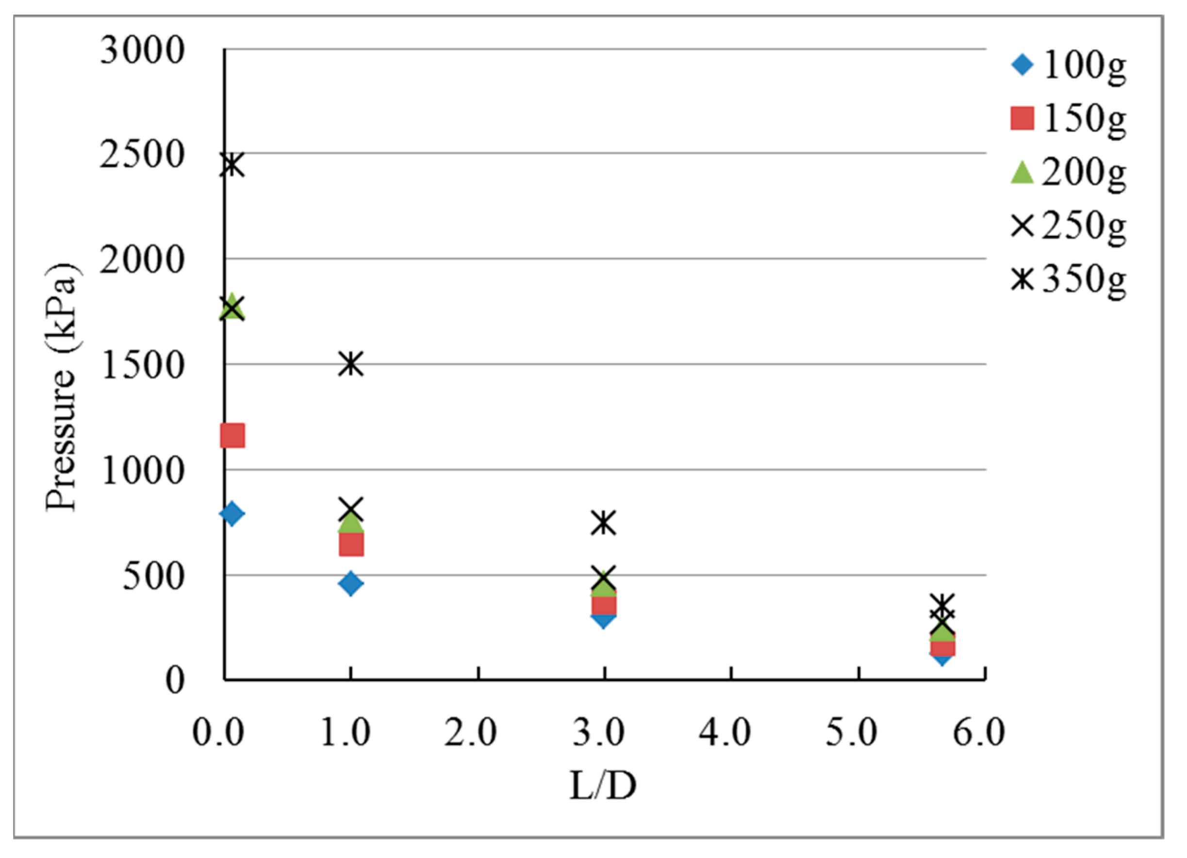
Figure 1. Experimental configuration and specimen of the linear tunnel with expansion chamber.
Applsci 11 05646 g001
Figure 2. Experimental configuration and specimen of linear tunnel with single-pressure relief orifice plate.
Applsci 11 05646 g002
Figure 3. Experimental configuration and specimen of the linear tunnel with double-pressure relief orifice plate.
Applsci 11 05646 g003
Figure 4. Schematic diagram of numerical models of pressure reduction modules.
Applsci 11 05646 g004
Figure 5. Comparison diagram of explosion experiment results of linear tunnel with expansion chamber.
Applsci 11 05646 g005
Figure 6. Blast transfer in numerical simulation of linear tunnel with expansion chamber explosion (100 g C-4).
Applsci 11 05646 g006
Figure 7. Comparison diagram of explosion experiment results of linear tunnel with single-pressure relief orifice plate.
Applsci 11 05646 g007
Figure 8. Blast transfer of numerical simulation of linear tunnel with single-pressure relief orifice plate explosion (100 g C-4).
Applsci 11 05646 g008
Figure 9. Comparison diagram of double-pressure relief orifice plate explosion experiment results.
Applsci 11 05646 g009
Figure 10. Blast transfer in numerical simulation of linear tunnel with double-pressure relief orifice plate explosion (100 g C-4).
Applsci 11 05646 g010
Table 1. Comparison of experiment and numerical results of linear tunnel with expansion chamber.
Weight of C-4 (g)100150200250350
PositionP1
(L/D = 0.07)
ExperimentExplosion pressure (kPa)999.271276.141327.741834.182873.28
Simulation889.321207.761553.811725.412281.28
P2
(L/D = 1.00)
ExperimentExplosion pressure (kPa)492.06600.50593.31766.601158.69
Simulation591.04747.45872.07967.591133.06
P3
(L/D = 3.00)
ExperimentExplosion pressure (kPa)282.81417.29427.71468.46664.85
Simulation449.52554.88639.48700.86816.89
P4
(L/D = 5.67)
ExperimentExplosion pressure (kPa)189.52237.99332.31384.24443.45
Blast transfer rate ( R t r a n s f e r )0.670.570.780.820.67
Average: 0.7
SimulationExplosion pressure (kPa)244.00304.74354.77391.55462.05
Blast transfer rate ( R t r a n s f e r )0.540.550.550.560.57
Average: 0.55
Table 2. Comparison of experiment and numerical results of steel tunnel with single-pressure relief orifice plate.
Weight of C-4 (g)100150200250350
PositionP1
(L/D = 0.07)
ExperimentExplosion pressure (kPa)784.671164.001777.001763.022443.99
Simulation792.961006.731623.961721.412175.51
P2
(L/D = 1.00)
ExperimentExplosion pressure (kPa)457.43642.93760.66908.141502.18
Simulation584.15739.17863.49960.171126.15
P3
(L/D = 3.00)
ExperimentExplosion pressure (kPa)300.49367.77454.65482.50747.77
Simulation568.95617.27655.25702.23837.73
P4
(L/D = 5.67)
ExperimentExplosion pressure (kPa)123.89170.62242.00272.76348.09
Blast transfer rate ( R t r a n s f e r )0.410.460.530.570.47
Average: 0.49
SimulationExplosion pressure (kPa)117.91144.36166.38182.05211.96
Blast transfer rate ( R t r a n s f e r )0.210.230.250.260.25
Average: 0.24
Table 3. Comparison of experiment and numerical results of steel tunnel with double-pressure relief orifice plate.
Weight of C-4 (g)100150200250350
PositionP1
(L/D = 0.07)
ExperimentExplosion pressure (kPa)711.49779.041568.81950.372294.61
Simulation792.961006.731523.111786.342204.64
P2
(L/D = 1.00)
ExperimentExplosion pressure (kPa)379.33454.14686.29782.28986.88
Simulation584.15739.17863.49960.171126.15
P3
(L/D = 3.00)
ExperimentExplosion pressure (kPa)272.79306.57450.01544.88703.04
Simulation651.38780.52739.47787.03843.57
P4
(L/D = 5.67)
ExperimentExplosion pressure (kPa)38.1852.3371.64108.96166.3
Blast transfer rate ( R t r a n s f e r )0.140.170.160.200.24
Average: 0.18
SimulationExplosion pressure (kPa)65.40101.19116.50128.89151.12
Blast transfer rate ( R t r a n s f e r )0.100.130.160.160.18
Average: 0.15
Table 4. Percentage error of different pressure attenuation models.
Weight of C-4100 g150 g200 g250 g350 g
Expansion chamberP111%5.4%17%5.9%20.6%
P220%24%46%26.2%2.21%
P359%33%49%49.6%22.8%
P429%28%6.8%1.9%4.2%
Single-orifice plateP11%13.5%8.6%2.3%10.9%
P227.7%14.9%13.5%5.7%25%
P389.3%67.9%44.1%45.5%12%
P44.8%15.4%31.2%33.3%39.1%
Double-orifice plateP111.4%29.3%2.9%8.4%3.9%
P253.9%62.7%25.8%22.7%14.1%
P3138%154%64.3%44.4%19%
P471.2%93.3%62.6%18.3%9.12%
Publisher’s Note: MDPI stays neutral with regard to jurisdictional claims in published maps and institutional affiliations.

