Article

Fabrication of a Simultaneous Highly Transparent and Highly Hydrophobic Fibrous Films

New Materials Research Group, Electronics and Telecommunications Research Institute, 218 Gajeong-ro, Yuseong-gu, Daejeon 34129, Korea
*
Author to whom correspondence should be addressed.
Appl. Sci. 2021, 11(12), 5565; https://doi.org/10.3390/app11125565
Submission received: 27 April 2021 / Revised: 31 May 2021 / Accepted: 7 June 2021 / Published: 16 June 2021
(This article belongs to the Special Issue Advances of Electrospun Nanofibers, Nanocomposites and Microparticles)

Abstract

:
This paper discusses the fabrication and characterization of electrospun nanofiber scaffolds made of polystyrene (PS). The scaffolds were characterized in terms of their basis material molecular weight, fiber diameter distribution, contact angles, contact angle hysteresis, and transmittance. We propose an aligned electrospun fiber scaffold using an alignment tool (alignment jig) for the fabrication of highly hydrophobic (θW > 125°) and highly transparent (T > 80.0%) films. We fabricated the alignment jig to align the electrospun fibers parallel to each other. The correlation between the water contact angles and surface roughness of the aligned electrospun fibers was investigated. We found that the water contact angle increased as the surface roughness was increased. Therefore, the hydrophobic properties of the aligned electrospun fibers were enhanced by increasing the surface roughness. With the change in the electrospinning mode to produce aligned fibers rather than randomly distributed fibers, the transmittance of the aligned electrospun fibers increased. The increase in the porous area, leading to better light transmittance in comparison to randomly distributed light scattering through the aligned electrospun fibers increased with the fibers. Through the above investigation of electrospinning parameters, we obtained the simultaneous transparent (>80%) and hydrophobic (θW > 140°) electrospun fiber scaffold. The aligned electrospun fibers of PS had a maximum transmittance of 91.8% at the electrospinning time of 10 s. The water contact angle (WCA) of the aligned electrospun fibers increased from 77° to 141° as the deposition time increased from 10 s to 40 s. The aligned fibers deposited at 40 s showed highly hydrophobic characteristics (θW > 140°).

Graphical Abstract

1. Introduction

Recently, building integrated photovoltaics (BIPV) have received great attention as a renewable and non-polluting energy, and together with energy efficiency, zero energy and zero emission buildings are ever increasing. To become a zero energy or zero emission building, solar cells are integrated within the climate envelopes of buildings and utilizing solar radiation to produce electricity. BIPV offer an economical and technical solution to integrate solar cells harvesting solar radiation to produce electricity within the climate envelopes of buildings. Self-cleaning property receives attention in applications such as building walls. The most commonly used concepts for self-cleaning surfaces are hydrophobicity. The hydrophobicity for self-cleaning comes from the assumption that rolling water droplets down the hydrophobic surface will pick up dirt and become washed away. One of the tools to realize self-cleaning includes textiles and fabrics. Electrospinning is an effective process for fabrication of high surface-to-volume ratio and the generation of rough surface. Several researches have been able to produce electrospun surfaces with hydrophobicity. Such property comes about from a combination of surface texture and material used [1,2,3,4,5,6,7,8,9,10,11,12]. The rough surfaces composed of electrospun textiles with contact angle greater than 90° defines as hydrophobic surface [13]. Additionally, high-hydrophobic surfaces with high contact angles (>120°) exhibited self-cleaning due to their non-adhesive and non-wetting features [14,15,16]. Recently, many researches on highly hydrophobic surfaces with high water contact angle (WCA) of the electrospun fibers have been published [17,18,19]. The various application of the electrospun fibers such as transparent conducting film, stretchable electrode, and gas sensing material have been demonstrated [20,21,22]. In this study, we examined the influences of electrospun fiber alignment on the optical transmittance and water contact angle to obtain transparent and self-cleaning solar cells (TSC). The uniaxially oriented electrospun polystyrene (PS) fiber scaffolds were produced by employing our two dimensionally aligning jigs as the collector in electrospinning [21]. The transmission characteristics of the randomly distributed fibers and the aligned fibers were measured using UV-Visible transmission spectroscopy. Surface roughness of the randomly distributed fibers and the aligned fibers were analyzed based on atomic force microscope (AFM) images. The distributions in the fiber diameter of the randomly distributed fibers and the aligned fibers were investigated with scanning electron microscopy (SEM) micrographs.

2. Materials and Methods

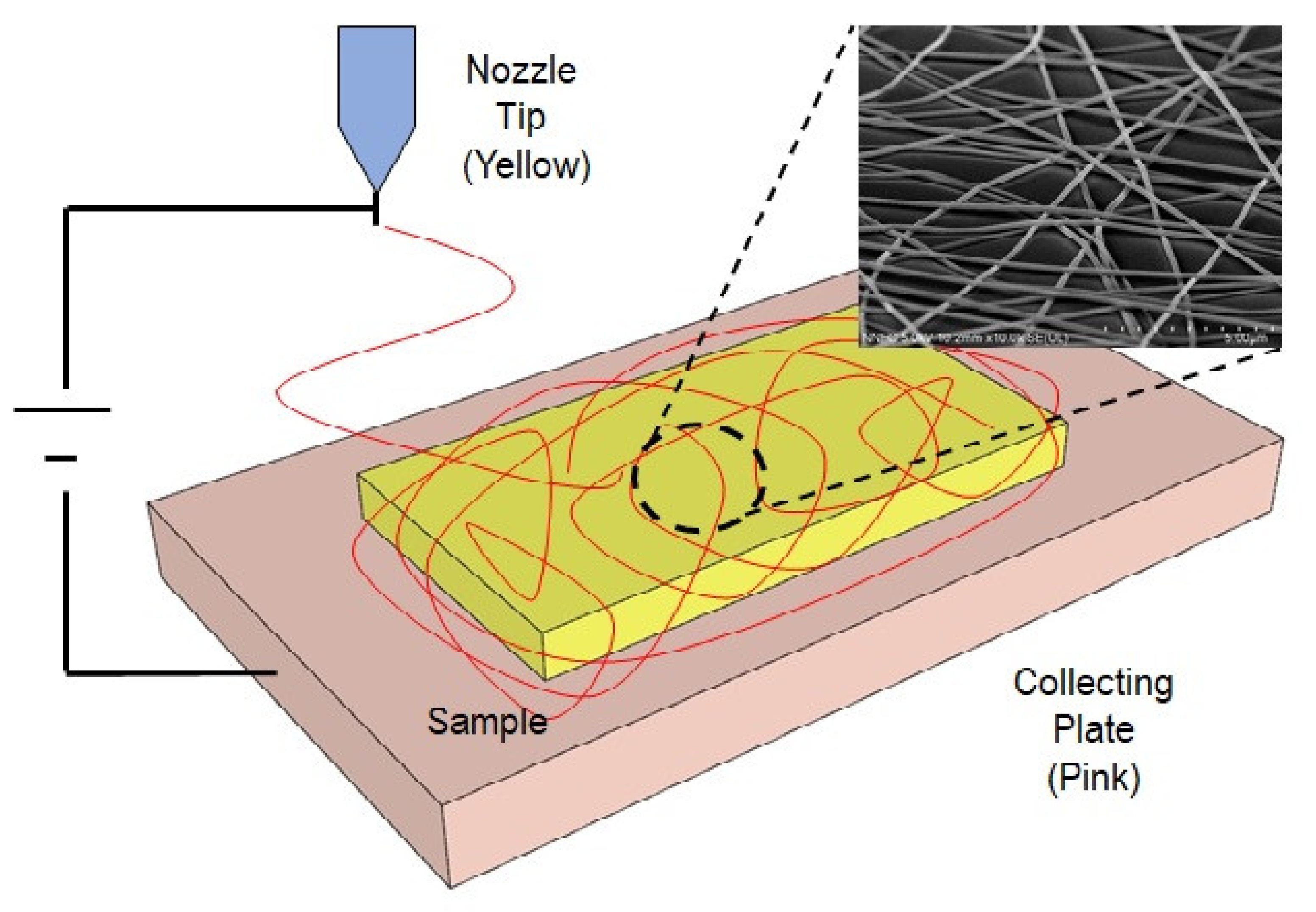
2.1. Production of Randomly Distributed Fibers

Figure 1 shows a compositional diagram of electrospinning equipment. It consists of the solution fluid component (top syringe feeder), the fiber-collecting component (bottom collector), and the power supplier between the nozzle tip and collector. High electric field strength is generated between the fluid control component contained in the glass syringe and the metallic collector. The PS was dissolved in a solution of dimethylformamide (DMF) solvents, and N-N-dimethylformamide (DMF)) was mixed with de-ionized water in a ratio of 100 to 10 by weight (10 w%). A voltage of 25 kV was applied between the nozzle tip (blue) and the collector (pink). The randomly distributed fiber scaffold was collected on the surface of the collecting plate (Figure 1).

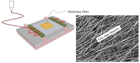
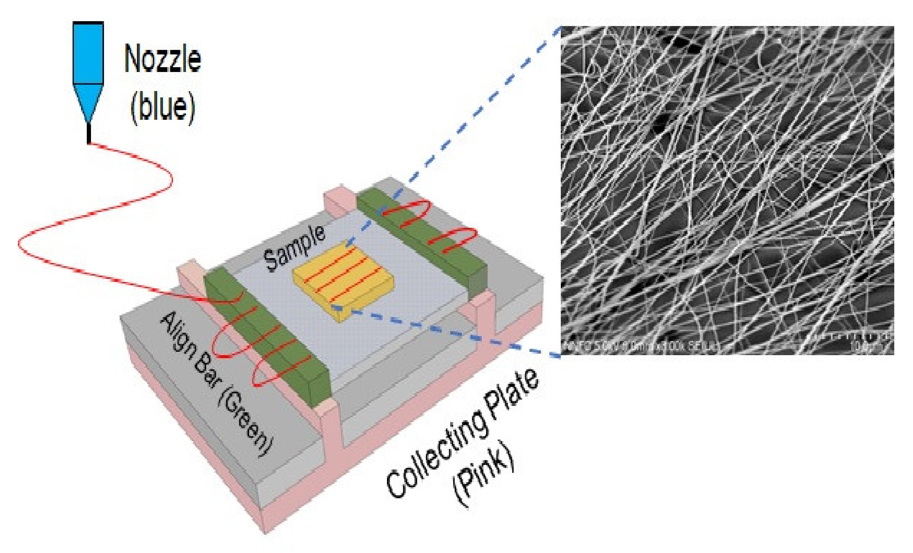
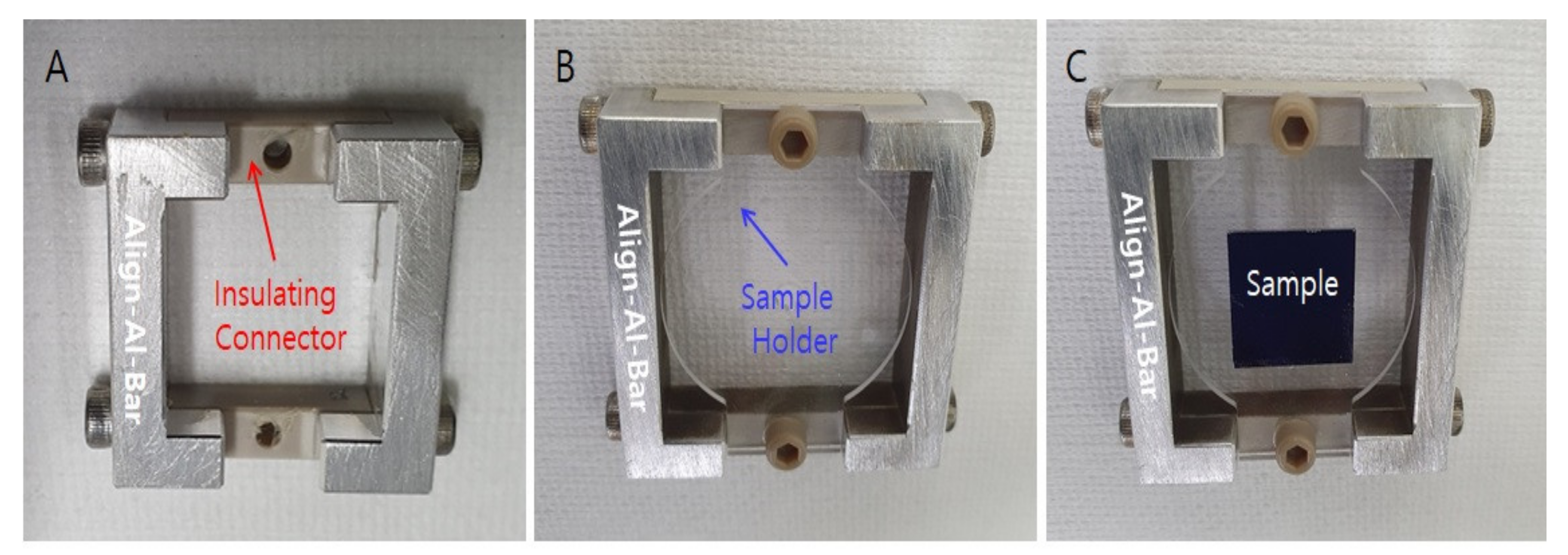
2.2. Fabrication of the Aligned Fibers

To increase the transmittance of the electrospun fibers, we aligned them parallel to each other. The alignment jig comprises two alignment bars which are located at two green bars (left and right) on the two protruded locations of collecting plate (pink). The fibers ejected from the nozzle tip point from the left alignment part (green) to the right alignment part (SEM image of Figure 2). Details of the alignment process are summarized in [9]. During electrospinning, a silicon substrate (yellow) is inserted into the sample holder (gray). The fibers ejected from the nozzle tip are collected on the surface of the substrate as shown in Figure 3.
The alignment bars and the protruding electrodes of the collecting plate bite each other as shown in Figure 3.
The steps in the alignment process are carried out as follows. First, an electrical isolation (insulating) gap (connector) is inserted between the two aluminum bars of the alignment jig (Figure 3A). Second, a sample holder is connected to the alignment jig (Figure 3B), Third, a sample is placed on the sample holder (Figure 3C). Finally, an electric field is applied between the nozzle tip and the collecting plate. The fibers ejected from the nozzle tip are aligned from the left alignment bar to the right alignment bar. Then, the electrospun fibers are annealed at 120 °C for 10 min. The number of electrospun fibers was increased as the electrospinning time increased.

2.3. Measurements and Characteristics

2.3.1. Materials and Solution Synthesis

PS with a molecular weight of 104.1 g/mol and density of 1060 kg/m3 was purchased from Aldrich. The PS was dissolved in a solution of DMF solvents. N-N-DMF mixed with de-ionized water in a ratio of 100 to 10 by weight (10 w%) produced consistent electrospun nanofiber scaffolds. The solvents were purchased from Aldrich. The solution was strongly stirred to ensure uniformity. A voltage of 25 kV was applied between the nozzle tip (blue) and the collecting plate (pink). PS powder was dissolved using a 10 wt% DMF solution. The solution feed rate was maintained at 0.1 mL/h for stable electrospinning. The thickness of the electrospun fibers was controlled by increasing the deposition time from 10 s to 40 s.

2.3.2. Contact-Angle Measurements

The water contact angle of electrospun fibers was measured by using a contact-angle meter (Drop Shape Analyzer DSA 25E, Kruss, Hamburg, Germany) at room temperature (22–25 °C). The volume of the droplets on the surface of the electrospun scaffolds was 15 µL. The contact-angle measurements were carried out over a 1 min period with a 1 or 2 s step to capture the time-dependent shaping of the drop. Advancing contact angles on the electrospun fibers and polymer films were measured by pipetting droplets of 3 µL volume on the surfaces using deionized (DI) water. Experiments were carried out at 22 °C and 50% humidity. Immediately after liquid deposition, images of the droplets were taken.

2.3.3. Scanning Electron Microscopy

Samples with the size of 9 mm × 9 mm were installed on the stage of a scanning electron microscope (SEM). Before scanning, platinum (Pt) was coated onto the samples with the thickness of 30 nm using an Eiko IB3 sputter coater (Tokyo, Japan). The surface morphology of the electrospun fibers was analyzed using a Hitachi TM3000 (Tokyo, Japan) at a 15 kV accelerating voltage.

2.3.4. Atomic Force Microscopy

The nanofibers’ topography was further identified by AFM workshop’s atomic force microscopes (Hilton head island, USA) with intermittent tapping of a 10 μm × 10 μm area with the back-side of an aluminum-coated rectangular cantilever. The acquired topography AFM images were then subjected to post-analysis of surface roughness. Within the 10 μm × 10 μm area, we measured five points to obtain the root-mean-square (Rq, RMS) roughness.

2.3.5. Optical Transmittance Measurement

The light transmittance transparency of the nanofiber scaffold samples was measured by UV-Visible transmission spectroscopy (Lambda 750 model). The electrospun fiber scaffold samples produced with various electrospinning times of 10, 20, 30, and 40 s were examined. The light transmission area was 5 mm × 25 mm, and the scanned sample area of the electrospun fibers on glass was 25 mm by 30 mm.

3. Results

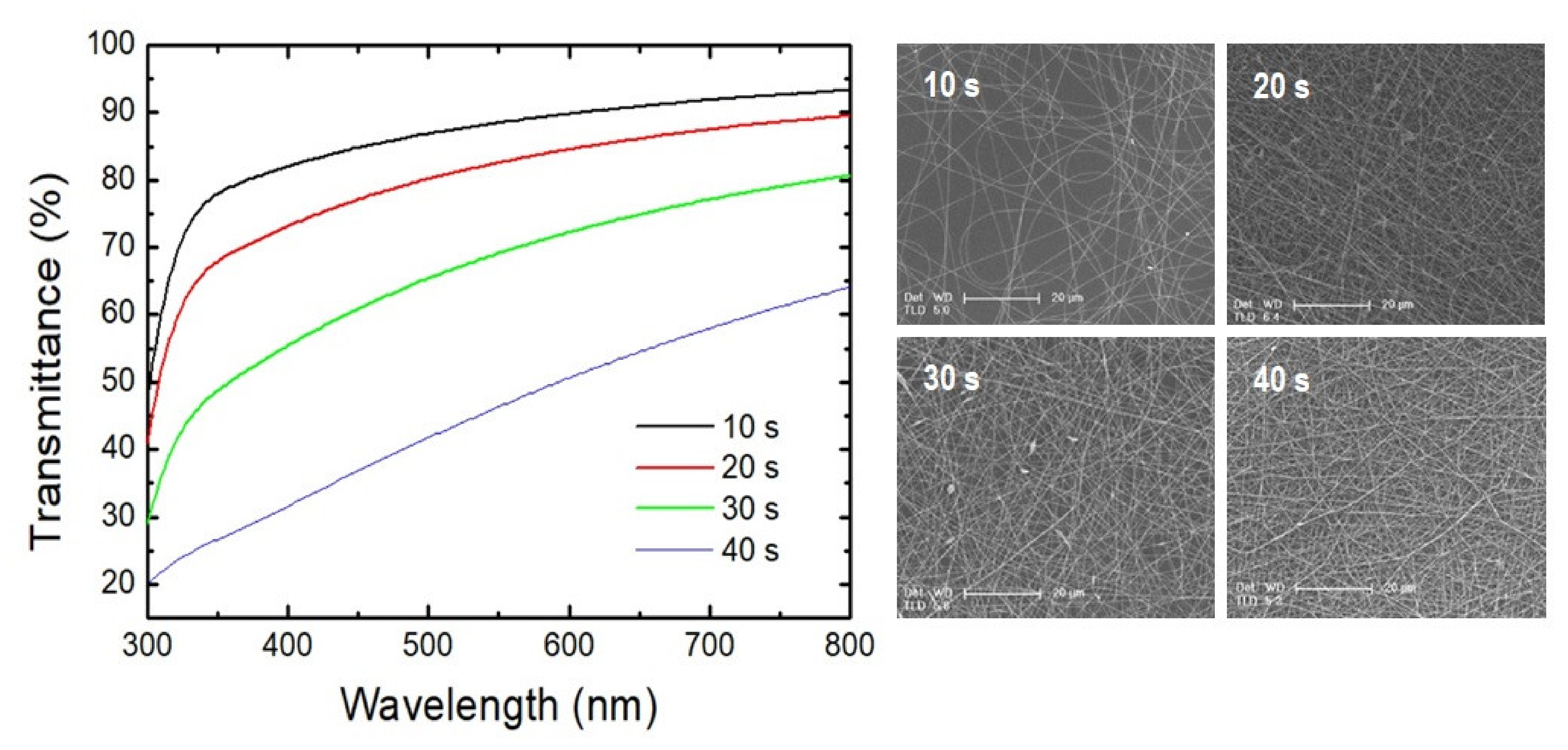
3.1. Transmission Characteristics of Randomly Distributed Fibers

The optical transmittance of the electrospun fiber samples decreased as the electrospinning time increased from 10 s to 40 s at 550 nm. Figure 4 shows the optical transmittance spectra of random networks of PS electrospun fibers. The measured transmittances of the random networks of PS fibers measured at 550 nm were 89.1% at deposition time of 10 s, 82.6% at 20 s, 69.2% at 30 s, and 46.4% at 40 s. The transmittance of the glass substrate was about 9.3%.

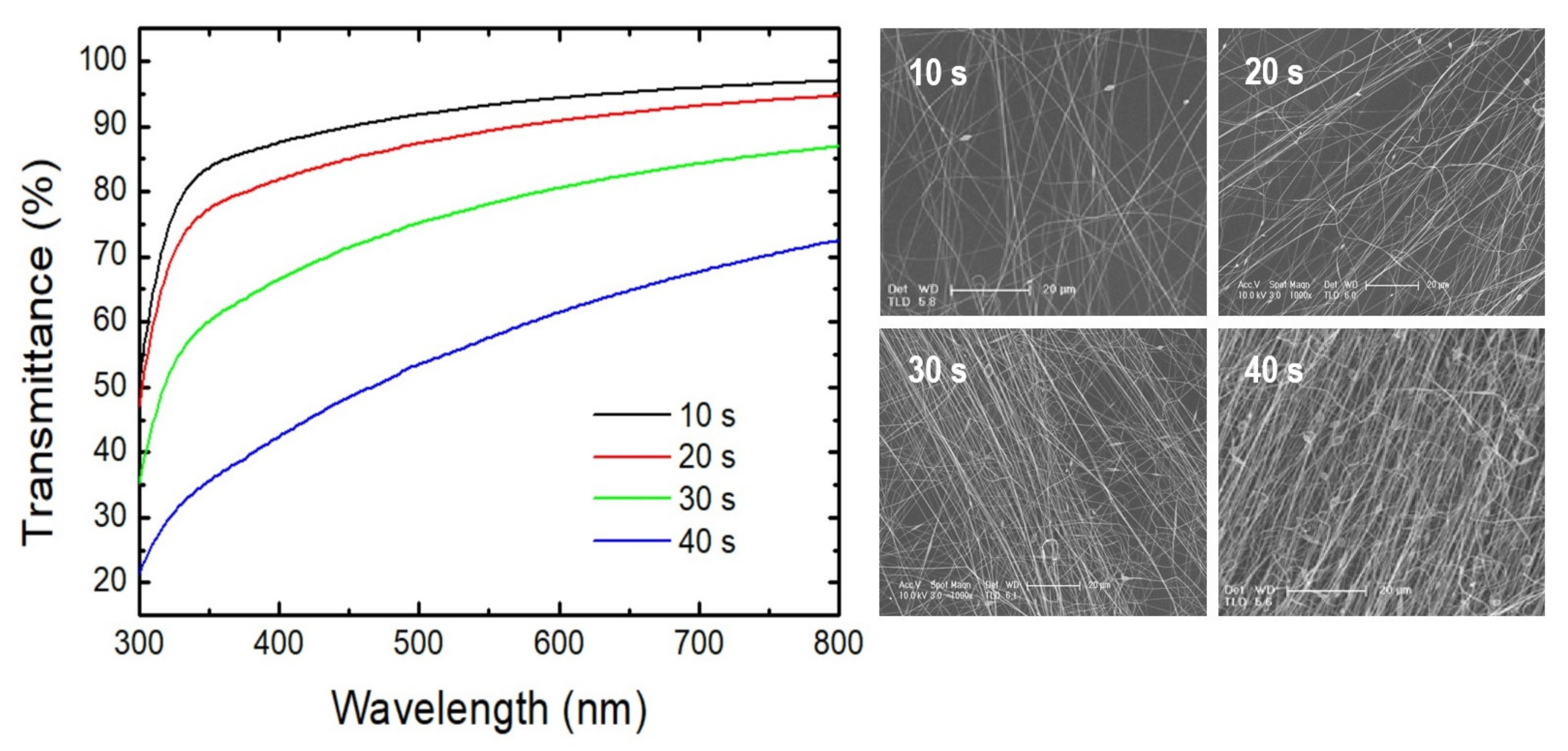
3.2. Transmission Characteristics of Aligned Fiber

Figure 5 shows the optical transmittance of the aligned fibers. The transmittance of the randomly distributed fibers was measured at 550 nm. The measured transmittances were 93.2% at a deposition time of 10 s, 89.2% at 20 s, 78.0% at 30 s, and 57.6% at 40 s. The transmittance of the bare glass substrate was 9.3%. As the density of PS fibers increased, the transparency decreased because of increased light scattering [22]. The transmittance decreased as the film thickness increased due to increasing reflection.

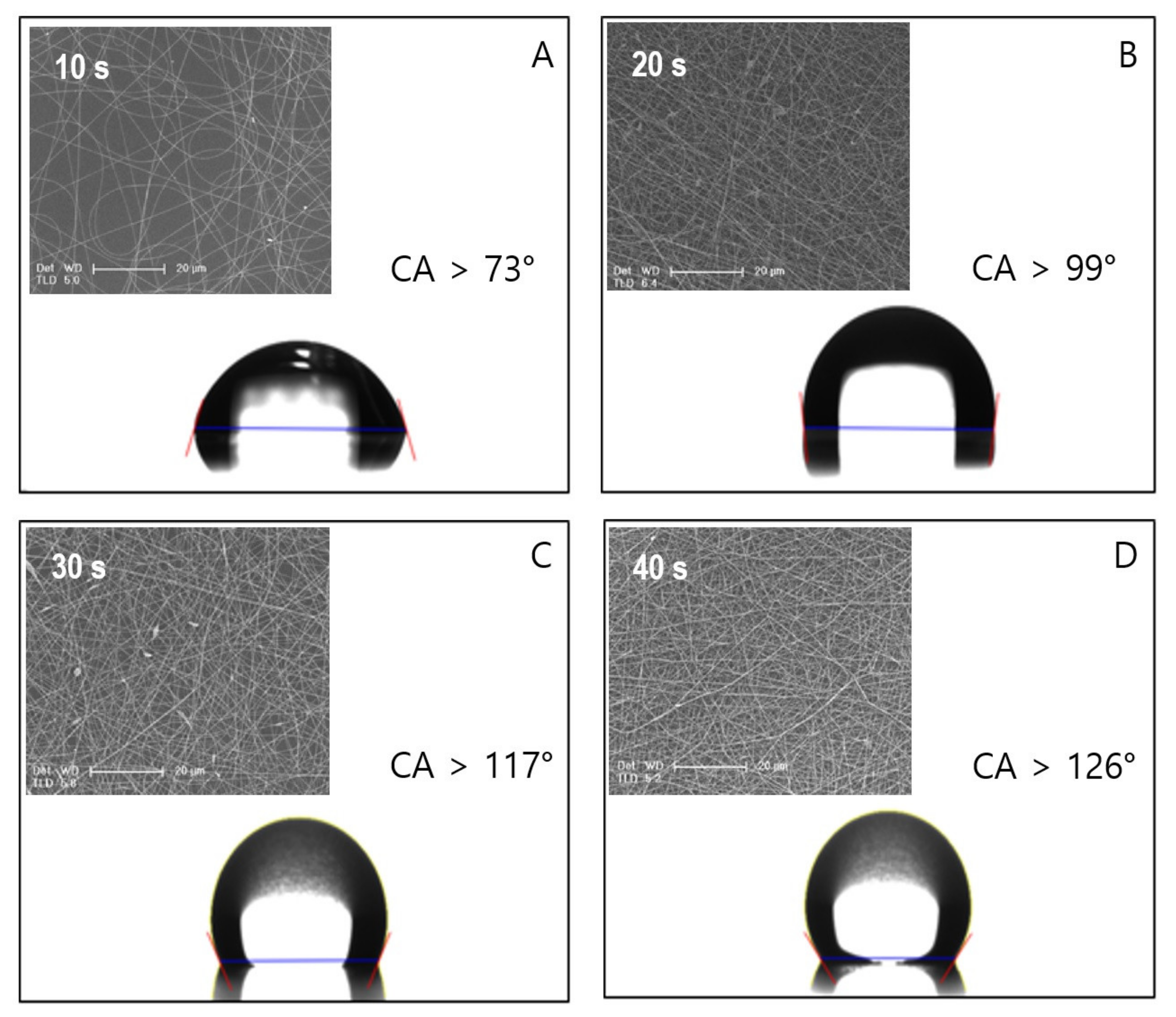
3.3. Hydrophobicity of the Randomly Distributed Fibers

Figure 6A–D show the WCAs of the random networks of electrospun PS fibers spun with deposition times of 10 s, 20 s, 30 s, and 40 s. The WCAs of the as-spun fibers depended on the duration of electrospinning. The WCA increased from 73° to 126° as the electrospinning time increased. Details of WCA measurement conditions and results are summarized in Tables S1 and S2 (Supplementary Materials). The scanning electron microscope (SEM) images of aligned electrospun fibers showed a rough and three-dimensional distribution as seen in Figure S1. However, the SEM images of the randomly distributed fibers showed a flat and two-dimensional distribution (Figure S2). Szewczyk et al., found that the water contact angle of electrospun fiber meshes increased as the surface roughness increased, while surface roughness increased as the electrospinning time increased. Surface roughness is the key parameter in the analysis of WCAs on electrospun meshes [23].

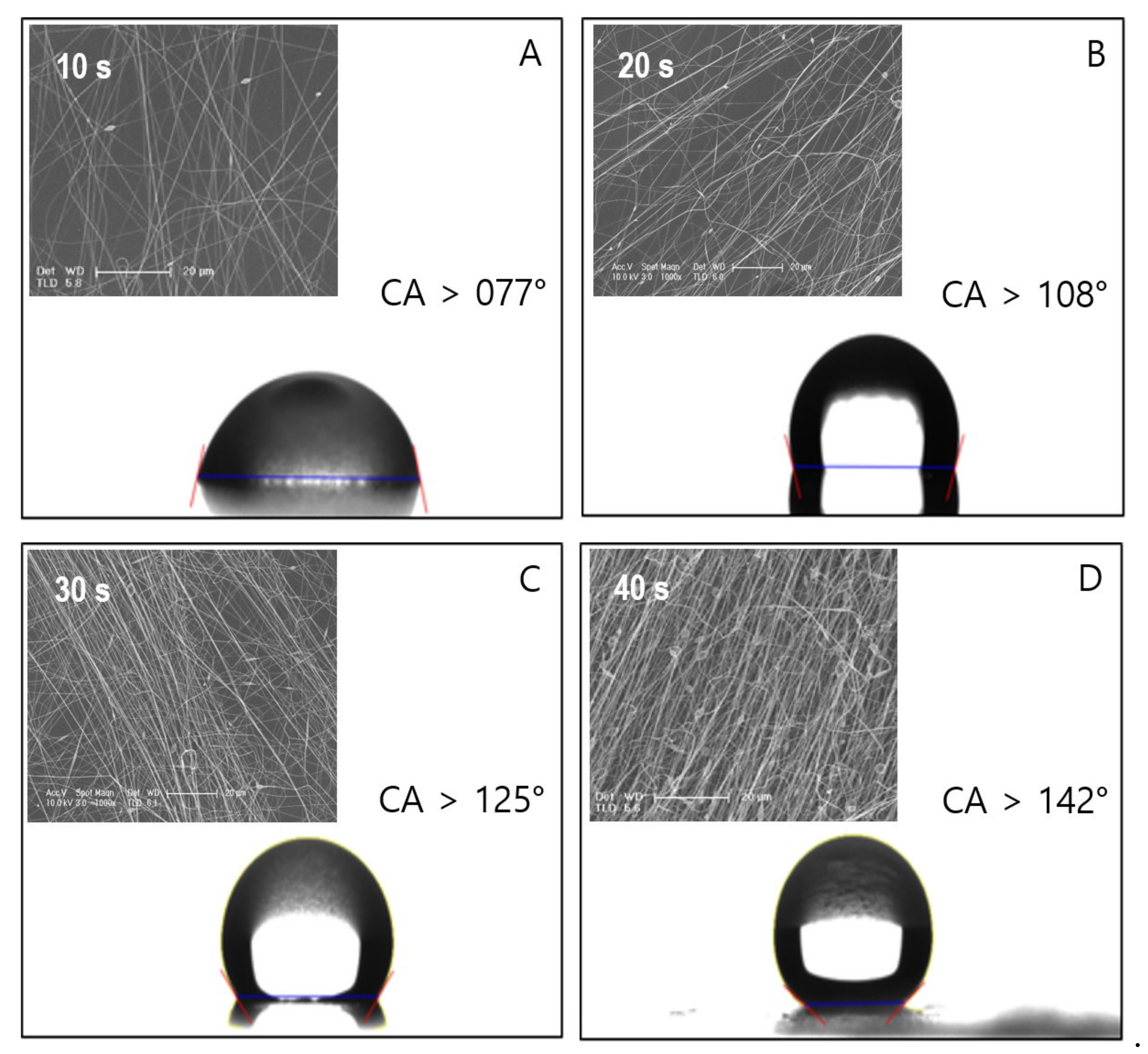
3.4. Hydrophobic Characteristics of Aligned Fibers

Figure 7A–D show the WCA plots of the aligned networks of electrospun PS fibers spun for durations ranging from 10 s to 40 s. The WCAs of the as-spun fibers depended on deposition time. The WCA increased from 77° to 142° as the electrospinning time increased, and the fiber density increased as the deposition time increased. Bagrov et al., reported that if the density of the electrospun fibers (surface coverage) is low and the distance (d) between the fibers is larger than the critical distance (dcrit) that allows a drop to penetrate down to the bottom of the sample (d > dcrit), the drop easily penetrates between the fibers and spreads onto the surface (surface contact). This “surface contact” state forms a smaller contact angle of less than 90° (hydrophilic) and follows the Wenzel model, which describes the contact between a drop and a surface. However, if the distance between the fibers is smaller than the critical distance (d < dcrit), the drop does not penetrate into the top layer of the fibers and floats on the fibers (surface float). This “surface float” state forms larger contact angle of more than 90° (hydrophobic) and follows the Cassie–Baxter model, which describes the contact between a drop and a floating fiber. Therefore, the increase in WCA is due to increased fiber density [24]. Details of the WCA measurement conditions and results are summarized in Table S2 (Supplementary Materials).

4. Discussion

4.1. High Transparency of the Aligned Fiber

In this study, we used two approaches to produce transparent hydrophobic surfaces. First, we decreased the diameter of the electrospun fibers. The light scattering was reduced by applying an electric field ranging from 15 kV (the applied voltage for the conventional electrospinning) to 25 kV (the applied voltage for the aligned electrospinning). Therefore, the thickness of the electrospun fibers decreased from micrometers to nanometers as the applied electric field decreased. Second, we aligned the electrospun fibers parallel to each other as shown in Figure 8A. However, the conventional randomly distributed electrospun fibers were cross-linked as shown in Figure 8B. The porous area where the light transmittance of the aligned electrospun fibers was higher than that of the randomly distributed electrospun fibers is shown in Figure 8. Therefore, the light scattering through the aligned electrospun fibers increased because of the increase in the porous area compared to that of the randomly distributed fibers. The specular transmittance spectrum of the aligned network was higher than that of the random network of PS electrospun fibers.

4.2. High Hydrophobicity of the Aligned Fibers

Figure 9 shows AFM images that reveal the surface morphology. The mean roughness values of the aligned fibers ranged from 360 ± 35 nm to 560 ± 130 nm; the mean roughness values of the randomly distributed fibers ranged from 175 ± 15 nm to 262 ± 90 nm. The average fiber diameter of the aligned fibers was 178 ± 25 nm as shown in Figure S1 (Supplementary Materials); the average fiber diameter of the randomly distributed fibers was 250 ± 50 nm as shown in Figure S2 (Supplementary Materials). The roughness values of the aligned fibers were higher than that of the randomly distributed fibers. Recently, Ura et al., observed that the water contact angle depends on the surface roughness [25,26,27,28,29]. In addition, Stachewicz et al., reported that when air is trapped inside the rough surface in grooves underneath a liquid drop, heterogeneous wetting occurs. This is described by the Cassie–Baxter contact model. The volume of air pockets underneath a liquid drop increases as the surface roughness increases. Therefore, the contact angles (hydrophobicity) of aligned fibers increased because of the increase in the surface roughness. The contact angle of the aligned fiber was higher than that of the randomly distributed fibers due to the higher surface roughness [30,31,32].

5. Conclusions

In this study, we demonstrated an aligned electrospun fiber scaffold. UV-Visible transmission spectroscopy showed an increased transmittance of up to 91.8% of aligned electrospun PS scaffolds, which is the key to enhancing the light absorption of a solar cell. Water contact angle (WCA) measurement by a contact angle meter showed an increased contact angle from 126° (randomly distributed fibers) to 142° (aligned fibers) at the same deposition time. Scanning electron microscope (SEM) images showed that the average fiber diameter of the aligned fibers was 178 ± 25 nm; the average fiber diameter of the randomly distributed fibers was 250 ± 50 nm. The atomic force microscope (AFM) images showed that the mean roughness values of the aligned fibers ranged from 360 ± 35 nm to 560 ± 130 nm; the mean roughness values of the randomly distributed fibers ranged from 175 ± 15 nm to 262 ± 90 nm. In summary, we obtained simultaneously highly hydrophobic (θW > 120°) and highly transparent (T > 80%) films with the electrospinning time of 30 s using the aligned electrospun fiber scaffolds. The aligned electrospun fibers enabled the production of PS scaffolds on the top of a glass substrate that were more transparent and more hydrophobic than the conventional randomly distributed electrospun fibers. The increased transmittance of aligned electrospun fibers leads to increased light absorption, and their hydrophobicity is likely to provide self-cleaning surfaces. The hydrophobicity and transparency of aligned electrospun fibers can play an important role in improving the efficiency of solar cells, such as transparent building integrated photovoltaics, known as BIPV.

Supplementary Materials

The following are available online at https://www.mdpi.com/article/10.3390/app11125565/s1, Table S1: Water contact angle obtained for randomly distributed electrospun fibers. Table S2: Water contact angle obtained for aligned electrospun fibers. Figure S1: Scanning electron microscope (SEM) image of randomly distributed electrospun fibers. The inset is the enlarged image of the fiber diameter. Figure S2: Scanning electron microscope (SEM) image of randomly distributed electrospun fibers. The inset is the enlarged image of the fiber diameter.

Author Contributions

Conceptualization, K.-S.L. and D.-H.Y.; methodology, S.-K.J.; validation, M.K.; writing—original draft preparation, D.-H.Y. All authors have read and agreed to the published version of the manuscript.

Funding

This work was supported by the ‘New & Renewable Energy’ of a Korea Institute of Energy Technology Evaluation and Planning (KETEP) grant funded by the Ministry of Trade, Industry & Energy (grant number 20193010014830).

Institutional Review Board Statement

Not applicable.

Informed Consent Statement

Not applicable.

Data Availability Statement

Not applicable.

Acknowledgments

The authors would like to thank Jang-Ung Park for the consultation of the electrospinning process at Nano Science Technology Institute, Department of Materials Science and Engineering, Yonsei University, Seoul 03722, Korea. Also thank Suck-Gil Han, Sung-Tae Park, Sang-Chul Hyun, and Jin-Young Oh for their cooperation in alignment jig designing at Tera Leader Co.

Conflicts of Interest

The authors declare no conflict of interest.

References

  1. Wu, R.; Chao, G.; Jiang, H.; Hu, Y.; Pan, A. The superhydrophobic aluminum surface prepared by diferent methods. Mater. Lett. 2015, 142, 176–179. [Google Scholar] [CrossRef]
  2. Hardman, S.J.; Muhamad-Sarih, N.; Riggs, H.J.; Thompson, R.L.; Rigby, J.; Bergius, W.N.A.; Hutchings, L.R. Electrospinning superhydrophobic fibers using surface segregating end functionalized polymer additives. Macromolecules 2011, 44, 6461–6470. [Google Scholar] [CrossRef] [Green Version]
  3. Meikandan, M.; Malarmohan, K.; Velraj, R. Development of superhydrophobic surface through facile dip coating method. Dig. J. Nanomater. Biostructures 2016, 11, 945–951. [Google Scholar]
  4. Diaa, B.M.; Jaafar, H.T. Superhydrophobic nanocomposites coating using electrospinning technique on different materials. Int. J. Appl. Eng. Res. 2017, 12, 16032–16038. [Google Scholar]
  5. Ding, Y.; Hou, H.; Zhao, Y.; Zhu, Z.; Fong, H. Electrospun polyimide nanofibers and their applications. Prog. Polym. Sci. 2016, 61, 67–103. [Google Scholar] [CrossRef]
  6. Ding, B.; Li, C.; Hota, Y.; Kim, J.; Kuwaki, O.; Shiratori, S. Conversion of an electrospun nanoibrous cellulose acetate mat from a super-hydrophilic to super-hydrophobic surface. Nanotechnology 2006, 17, 4332–4339. [Google Scholar] [CrossRef]
  7. Ogawa, T.; Ding, B.; Sone, Y.; Shiratori, S. Super-hydrophobic surfaces of layer-by-layer structured film-coated electrospun nanoibrous membranes. Nanotechnology 2007, 18, 165607. [Google Scholar] [CrossRef]
  8. Guo, Z.; Yang, F. Surfaces and Interfaces of Biomimetic Superhydrophobic Materials; John Wiley & Sons: Hoboken, NJ, USA, 2017; Chapter 5. [Google Scholar]
  9. Ahmed, B.; Mohamed, A.M.A.; Aboubakr, A.; Mariam, A.A.-M. Corrosion protection of electrospun PVDF-ZnO superhydrophobic coating. Surf. Coat. Technol. 2015, 285, 946–957. [Google Scholar]
  10. Huang, Z.M.; Zhang, Y.Z.; Kotaki, M.; Ramakrishna, S. A review on polymer nanofibers by electrospinning and their applications in nanocomposites. Compos. Sci. Technol. 2003, 63, 2223–2253. [Google Scholar] [CrossRef]
  11. Dzenis, Y. Material science: Spinning continuous fibers for nanotechnology. Science 2004, 304, 1917–1919. [Google Scholar] [CrossRef] [PubMed]
  12. Jin, S.; Park, Y.; Park, C.H. Preparation of breathable and superhydrophobic polyurethaneelectrospun webs with silica nanoparticles. Text. Res. J. 2016, 86, 124–129. [Google Scholar] [CrossRef]
  13. Nurxat, N.; Waseem, S.K.; Yu, L.; Muhammet, C.; Ramazan, A. Hydrophobic electrospun nanofibers. J. Mater. Chem. A 2013, 1, 1929–1946. [Google Scholar]
  14. Iurii, S.; Russell, E.G.; Jeff, A.J.; Kristin, A.T. Literature Review on Superhydrophobic Self-Cleaning Surfaces Produced by Electrospinning. J. Poly. Sci. 2012, 50, 824–845. [Google Scholar]
  15. Xue, C.H.; Jia, S.T.; Zhang, J.; Ma, J.Z. Large-area fabrication of superhydrophobic surfaces for practical applications: An overview. Sci. Technol. Adv. Mater. 2010, 11, 033002–033017. [Google Scholar] [CrossRef]
  16. Ma, M.; Hill, R.M.; Rutledge, G.C. A review of recent results on superhydrophobic materials based on micro-and nanofibers. J. Adhes. Sci. Technol. 2008, 22, 1799–1817. [Google Scholar] [CrossRef]
  17. Feng, X.J.; Jiang, L. Design and creation of superwetting/Antiwetting surfaces. Adv. Mater. 2006, 18, 3063–3078. [Google Scholar] [CrossRef]
  18. Ma, M.; Hill, R.M.; Lowery, J.L.; Fridrikh, S.V.; Rutledge, G.C. Electrospun Poly(Styrene-block-dimethylsiloxane) Block Copolymer Fibers Exhibiting Superhydrophobicity. Langmuir 2005, 21, 5549–5554. [Google Scholar] [CrossRef] [PubMed]
  19. Asmatulu, R.; Ceylan, M.; Nuraje, N. Study of Superhydrophobic Electrospun Nanocomposite Fibers for Energy Systems. Langmuir 2010, 27, 504–507. [Google Scholar] [CrossRef]
  20. Youn, D.-H.; Yu, Y.J.; Choi, J.S.; Park, N.M.; Yun, S.J.; Lee, I.; Kim, G.H. Transparent conducting films of silver hybrid films formed by near-field electrospinning. Mater. Lett. 2016, 185, 139–142. [Google Scholar] [CrossRef]
  21. Youn, D.-H.; Yeon, C.; Choi, J.S.; Park, N.M.; Lee, I.; Kim, G.H.; Yun, S.J. Arbitrary alignment-angle control method of the electrospun fibers: Potential for a stretchable electrode material. RSC Adv. 2017, 7, 44945–44953. [Google Scholar] [CrossRef] [Green Version]
  22. Youn, D.-H.; Kim, B.-J.; Yun, S.J. Synthesis and gas sensing properties of WS2 nanocrystallites assembled hierarchical WS2 fibers by electrospinning. Nanotechnology 2020, 31, 105602–105614. [Google Scholar] [CrossRef] [PubMed]
  23. Piotr, K.S.; Daniel, P.U.; Sara, M.; Joanna, K.-K.; Marcin, G.; Mateusz, M.M.; Andrzej, B.; Urszula, S. Roughness and Fiber Fraction Dominated Wetting of Electrospun Fiber-Based Porous Meshes. Polymers 2019, 11, 1–17. [Google Scholar]
  24. Bagrov, D.; Perunova, S.; Pavlova, E.; Klinov, D. Wetting of electrospun nylon-11 fibers and mats. RSC Adv. 2021, 11, 11373–11379. [Google Scholar] [CrossRef]
  25. Daniel, P.U.; Joanna, E.K.; Piotr, K.S.; Sara, M.; Mateusz, K.; Urszula, S. Cell Integration with Electrospun PMMA Nanofibers, Microfibers, Ribbons, and Films: A Microscopy Study. Bioengineering 2019, 6, 41–53. [Google Scholar]
  26. Koysuren, O.; Koysuren, H.N. Characterization of poly(methyl methacrylate) nanofiber scaffolds by electrospinning process. J. Macromol. Sci. Part A Pure Appl. Chem. 2016, 53, 691–698. [Google Scholar] [CrossRef]
  27. Konosu, Y.; Scaffoldsumoto, H.; Tsuboi, K.; Minagawa, M.; Tanioka, A. Enhancing the Effect of the Nanofiber Network Structure on Thermoresponsive Wettability Switching. Langmuir 2011, 27, 14716–14720. [Google Scholar] [CrossRef]
  28. Busolo, T.; Ura, D.P.; Kim, S.K.; Marzec, M.M.; Bernasik, A.; Stachewicz, U.; Kar-Narayan, S. Surface potential tailoring of PMMA fibers by electrospinning for enhanced triboelectric performance. Nano Energy 2019, 57, 500–506. [Google Scholar] [CrossRef]
  29. Szewczyk, P.K.; Knapczyk-Korczak, J.; Ura, D.P.; Metwally, S.; Gruszczyński, A.; Stachewicz, U. Biomimicking wetting properties of spider web from Linothele megatheloides with electrospun fibers. Mater. Lett. 2018, 233, 211–214. [Google Scholar] [CrossRef]
  30. Stachewicz, U.; Bailey, R.J.; Zhang, H.; Stone, C.A.; Willis, C.R.; Barber, A.H. Wetting Hierarchy in Oleophobic 3D Electrospun Nanofiber Networks: ACS Appl. Mater. Interfaces 2015, 7, 16645–16652. [Google Scholar]
  31. Vincent, M.; Thomas, H.; Heike, H.; Viola, V.; Daniel, E. Influence of the fiber diameter and surface roughness of electrospun vascular grafts on blood activation. Acta Biomater. 2012, 8, 4349–4356. [Google Scholar]
  32. Rasoul, M.; Javad, K.; Mojtaba, S.N.; Mohammad, A.K. Preparation and Characterization of Polyvinylidene Fluoride/Graphene hydrophobic Fibrous Films. Polymers 2015, 7, 1444–1463. [Google Scholar]
Figure 1. Schematic diagram of the electrospinning process to produce randomly distributed electrospun fibers.
Applsci 11 05565 g001
Figure 2. Diagram of the electrospinning system for parallel alignment of electrospun fibers.
Applsci 11 05565 g002
Figure 3. Alignment jig used in the electrospinning process for parallel (uniaxial) alignment of electrospun fibers. (A) Optical image of the alignment jig without sample and sample holder. (B) Optical image of the alignment jig with sample holder. (C) Optical image of the alignment jig with sample and sample holder.
Applsci 11 05565 g003
Figure 4. (Left) Transmittance spectra of randomly distributed PS fibers deposited with deposition times of 10 s, 20 s, 30 s, and 40 s. (Right) SEM images of the random networks of PS fibers.
Applsci 11 05565 g004
Figure 5. (Left) Transmittance spectra of the aligned PS fibers deposited with deposition times ranging from 10 s to 40 s. (Right) SEM images of the aligned networks of PS fibers.
Applsci 11 05565 g005
Figure 6. Water contact angle and SEM images of random networks of PS electrospun fibers deposited at (A) 10, (B) 20, (C) 30, and (D) 40 s. The applied voltage was 10 kV, and the working distance was 15 cm.
Applsci 11 05565 g006
Figure 7. Water contact angle and SEM images of the aligned network of PS electrospun fibers deposited with deposition times of (A) 10, (B) 20, (C) 30, and (D) 40 s. The applied voltage is 10 kV and the working distance is 15 cm.
Applsci 11 05565 g007
Figure 8. Cross-sections (dark area) of light scattering for both aligned fibers (A) and randomly distributed fibers (B).
Applsci 11 05565 g008
Figure 9. AFM images and the surface roughness for samples with aligned electrospun fibers (a,b) and samples with randomly distributed fibers (c,d). The inserted line (white and red) indicated the measured region.
Applsci 11 05565 g009
Publisher’s Note: MDPI stays neutral with regard to jurisdictional claims in published maps and institutional affiliations.

