
Effect of Cut-Off, Evaluation Length, and Measurement Area in Profile and Areal Surface Texture Characterization of As-Built Metal Additive Manufactured Components


Abstract
1. Introduction
- (1)
- Challenges in measuring as-built AM component surface (issues in selecting the appropriate cut-off wavelength and evaluation length). What proper evaluation length and cut-off filter to use for measurement in case of insufficient measurement length?
- (2)
- Will the results be affected by using different measurement cut-off and evaluation lengths than suggested under ISO 4288?
- (3)
- How to interpret the resulting surface roughness obtained by using cut-off and evaluation length suggested by ISO?
- (4)
- What is the deviation in the resulting roughness values obtained by selecting non-recommended cut-off, evaluation length, and nesting index values contrary to ISO standards?
- (5)
- Is it possible to obtain useful measurable information from scanning electron microscope (SEM) analysis on the as-built AM surfaces?
2. Manufacturing and Measurement Techniques
2.1. Manufacturing Method and Materials
2.2. Qualitative Analysis
2.3. Quantitative Analysis
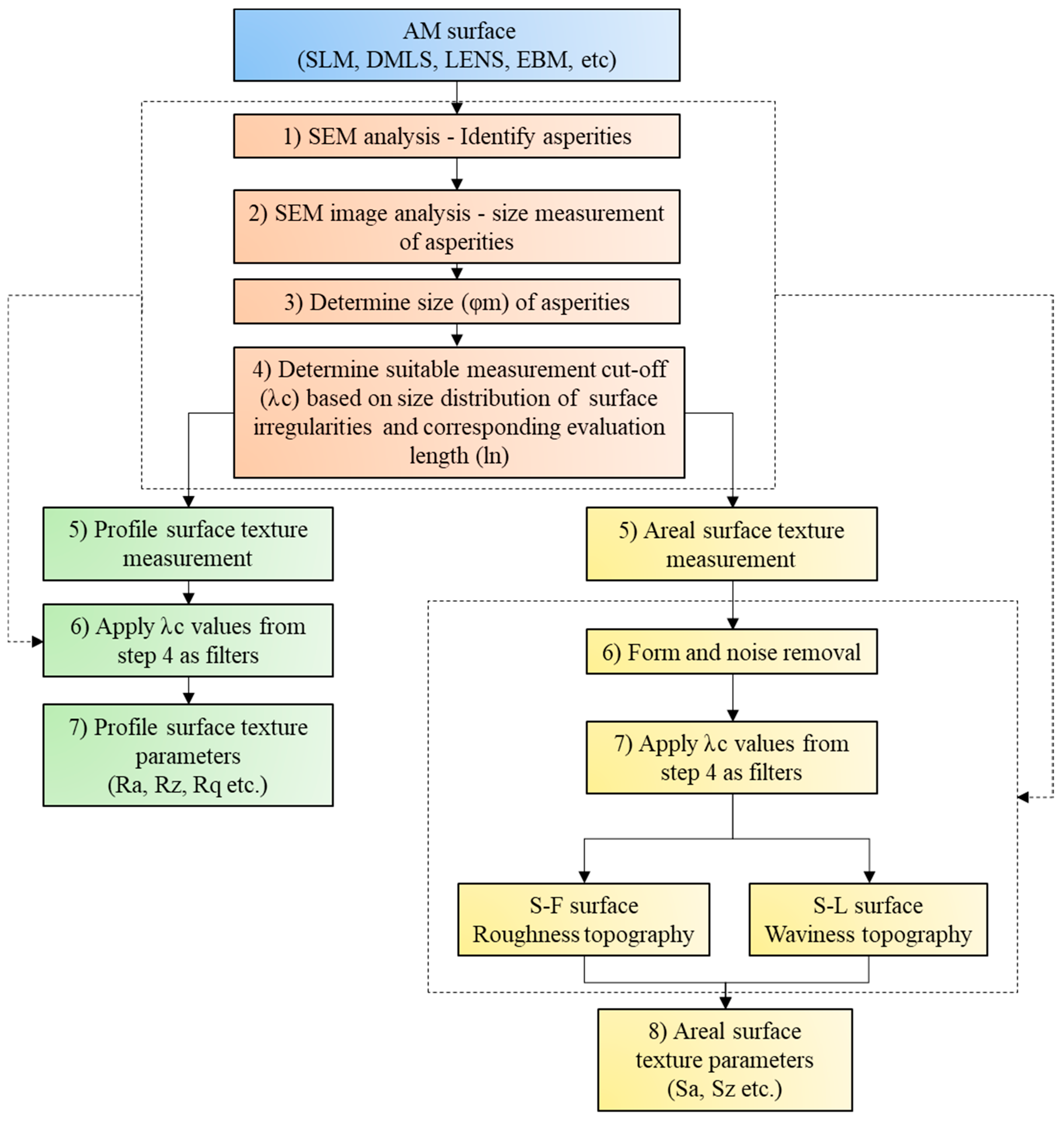
2.4. Investigative Measurement Framework
3. Results and Discussion
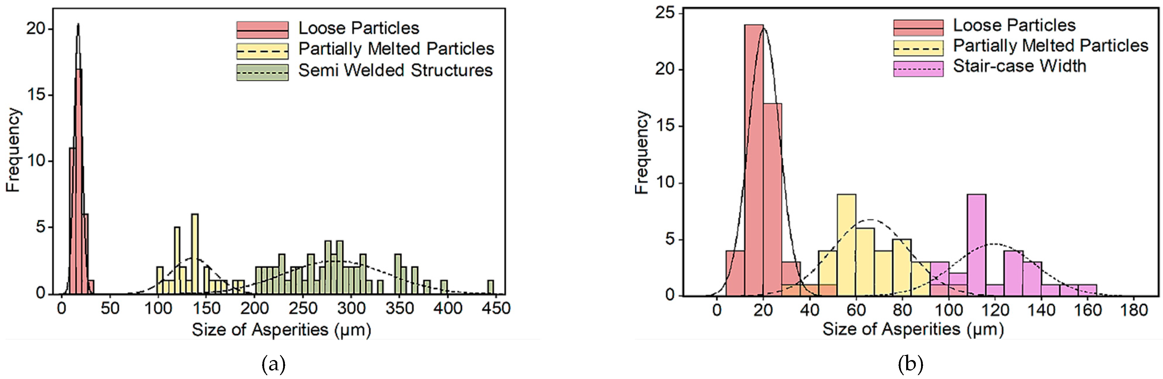
3.1. Scanning Electron Microscope (SEM) Analysis
Size Distribution of Surface Irregularities
3.2. Profile Surface Texture Analysis
3.2.1. Profile Surface Measurements—Effect of Various Cut-Off Wavelength and Evaluation Length
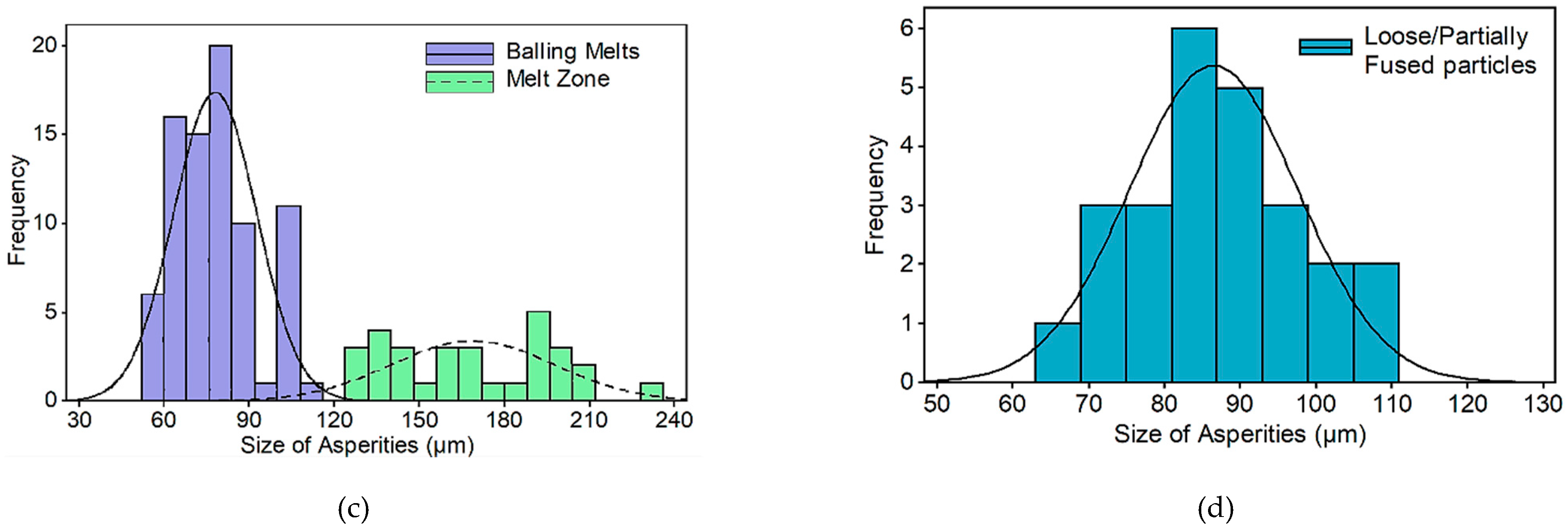
3.2.2. Percentage Deviation from the Reference Value
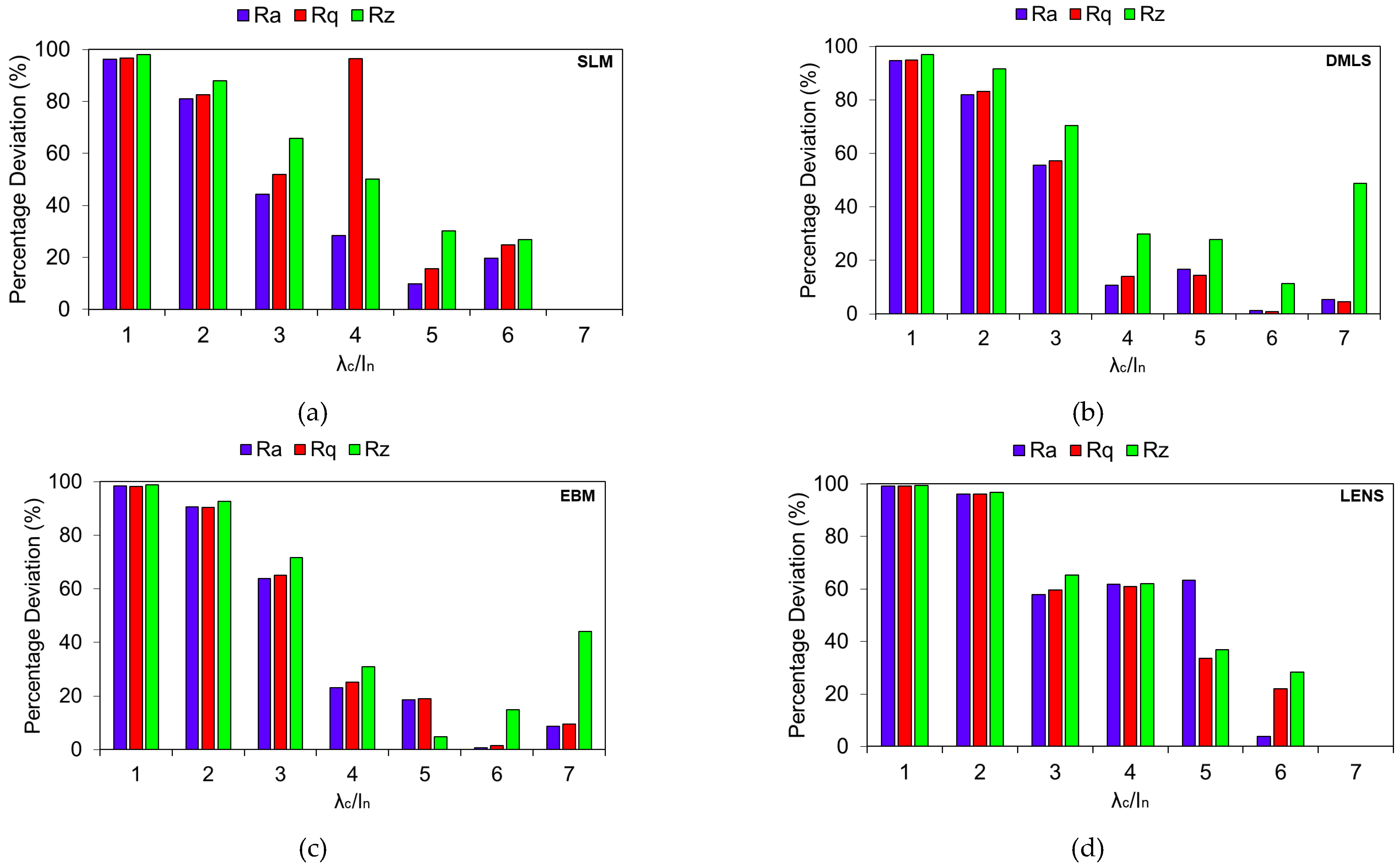
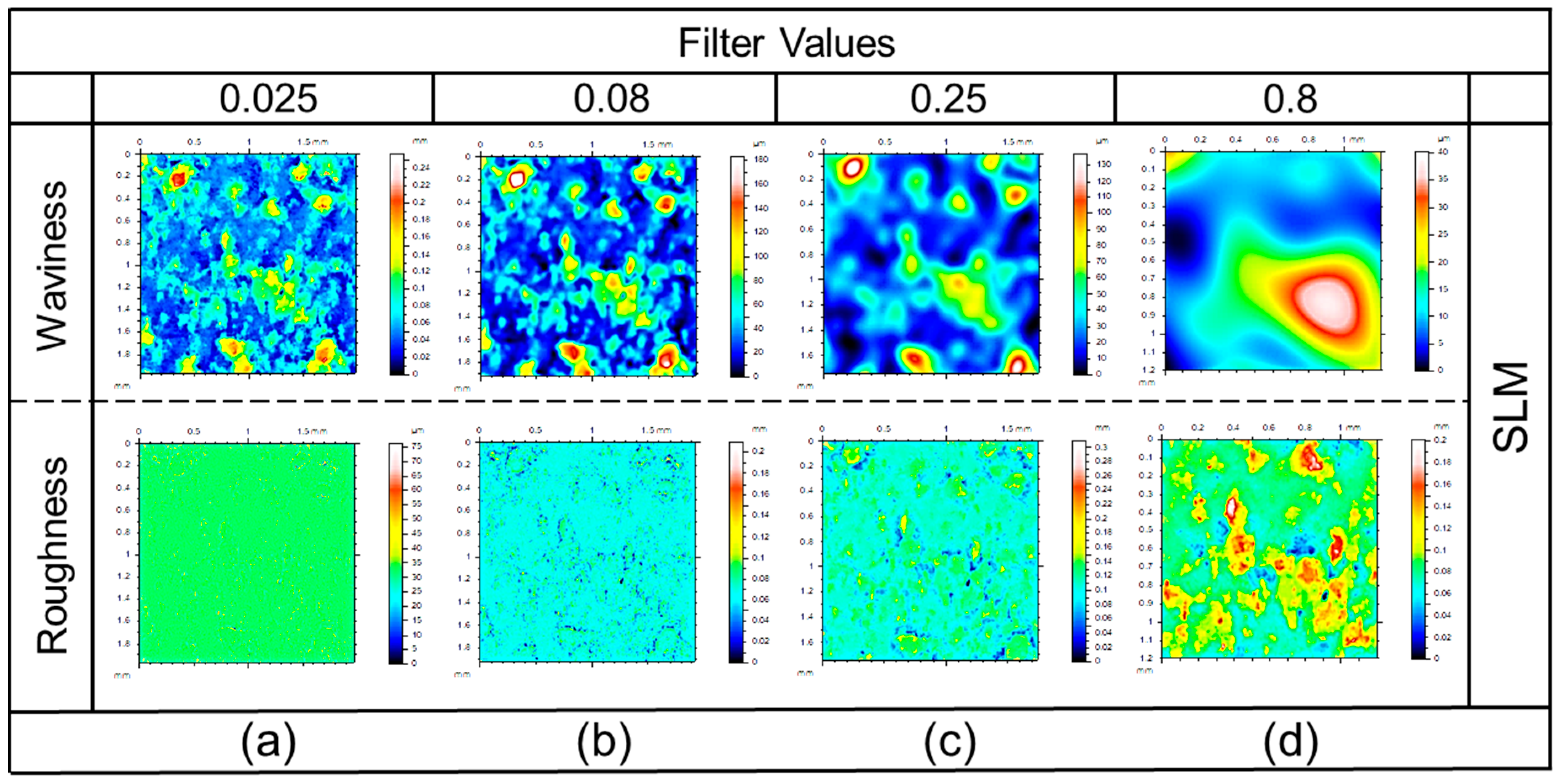
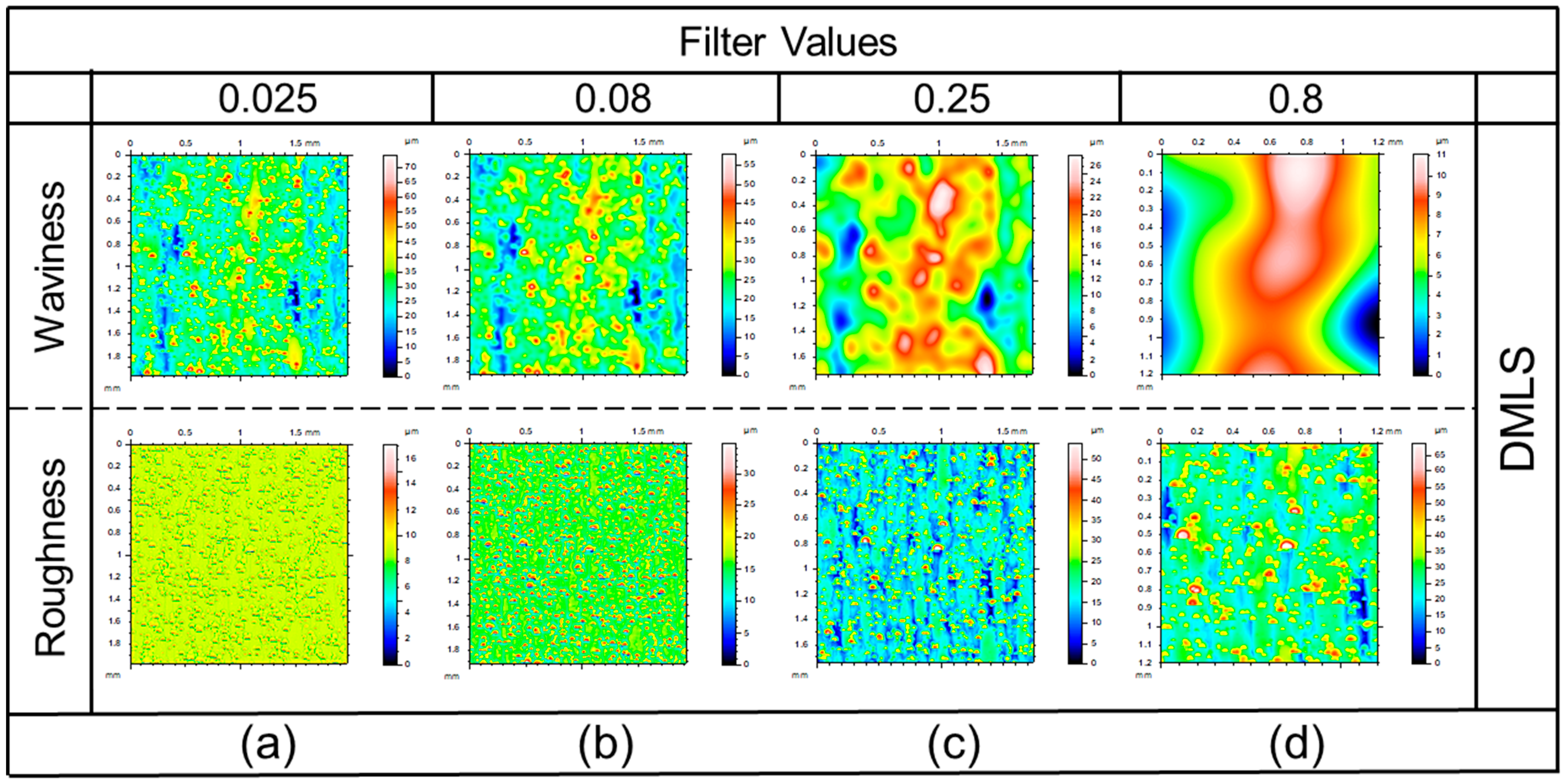
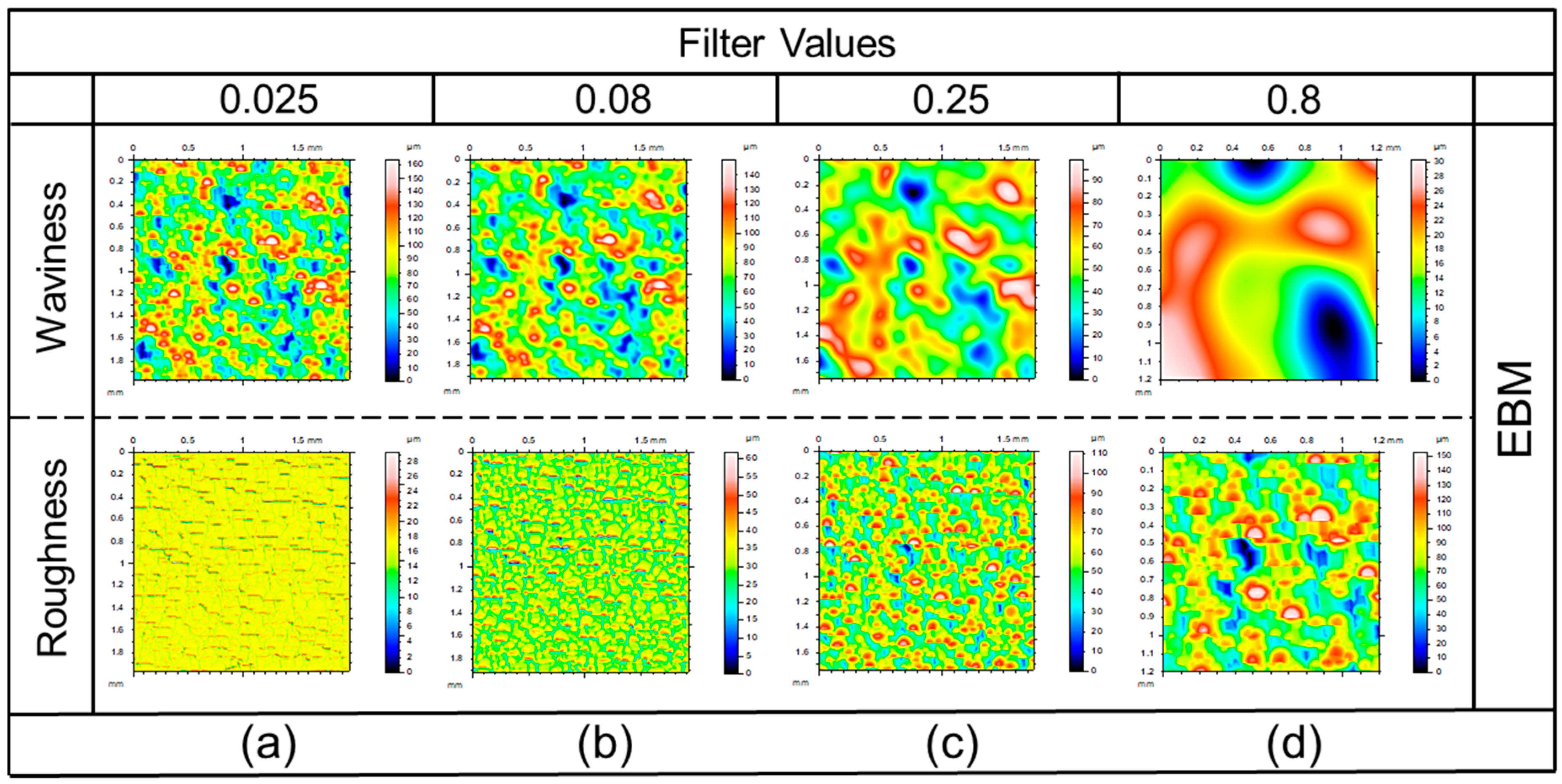
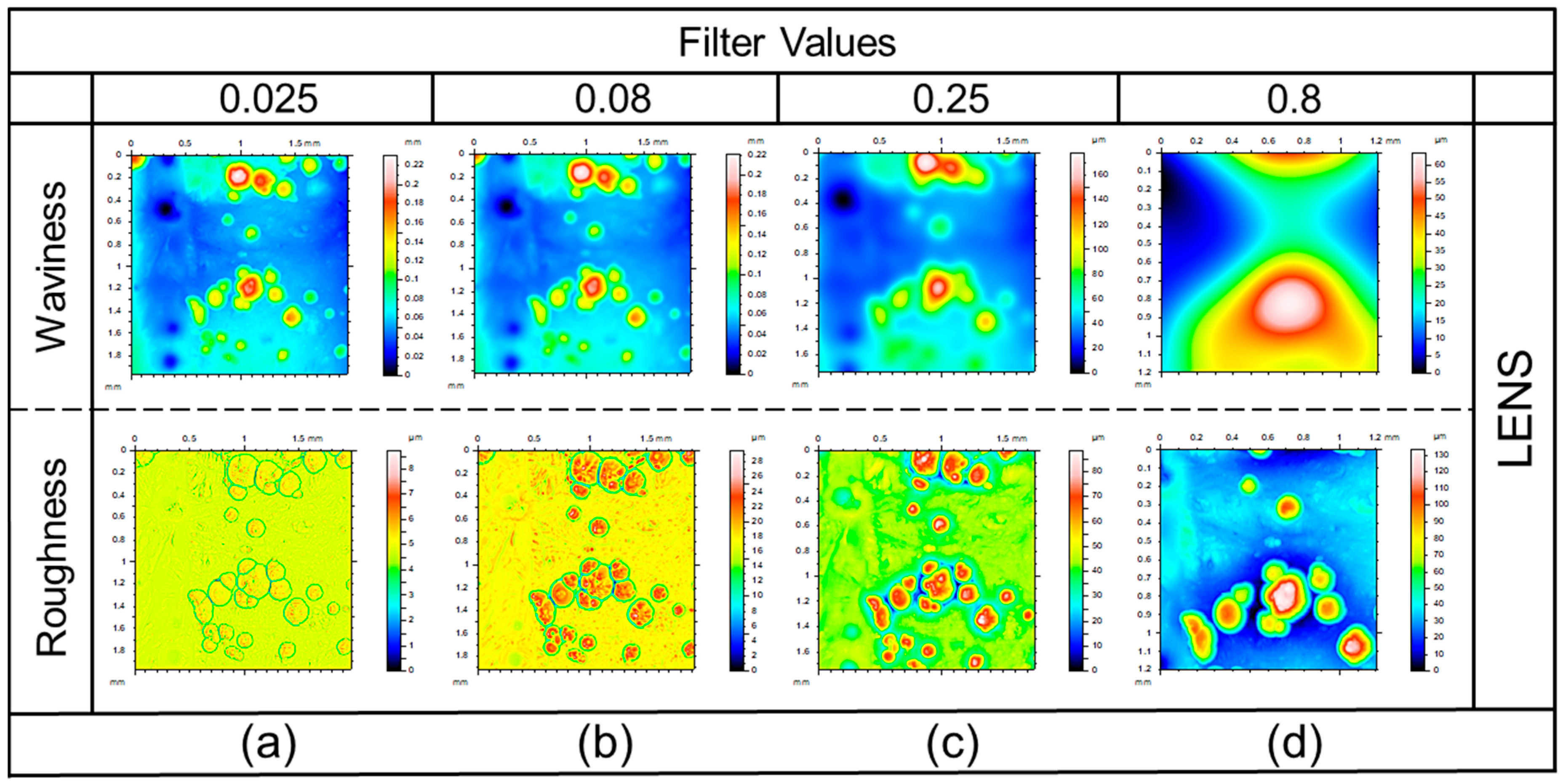
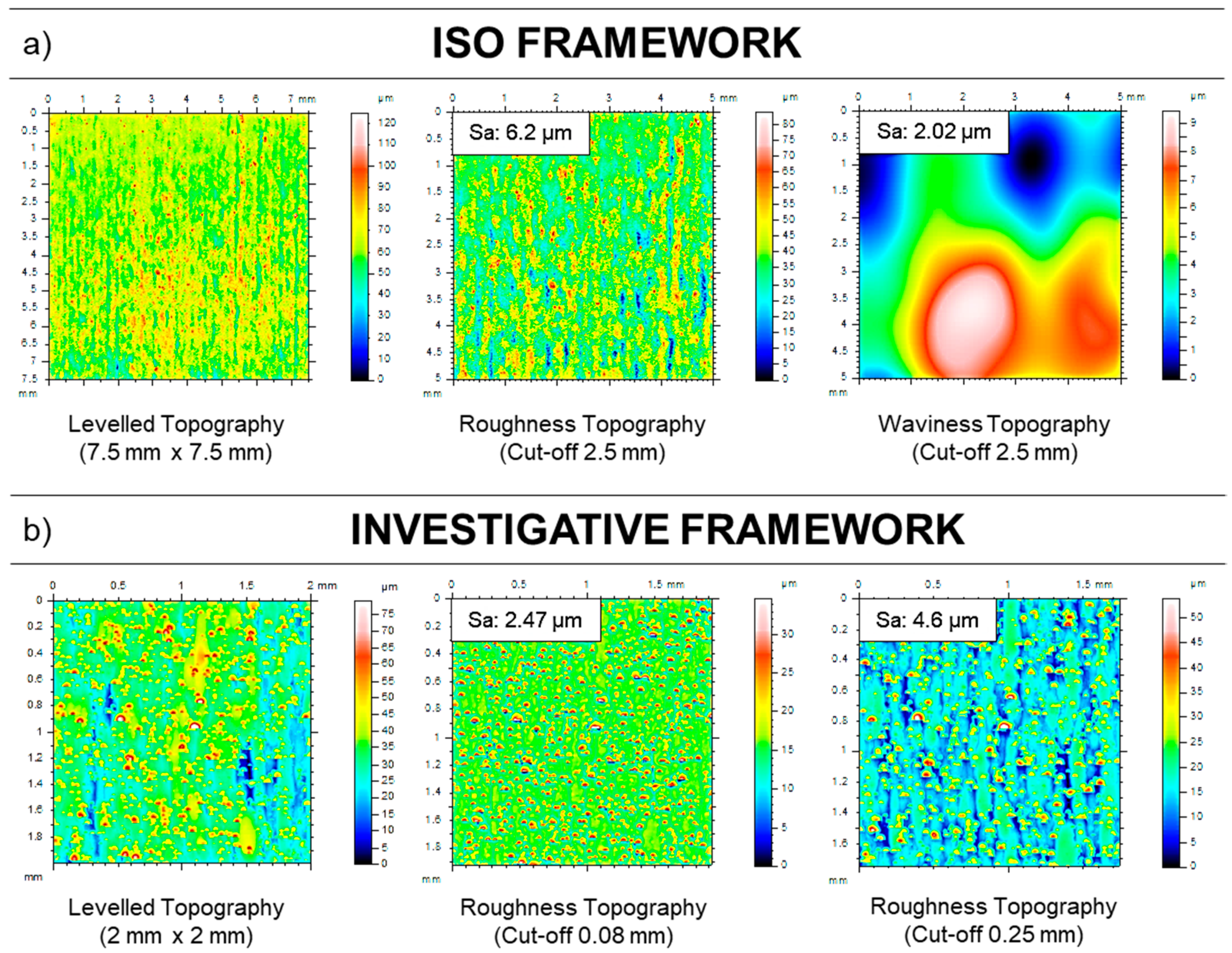
3.3. Areal Surface Texture Analysis
Areal Surface Measurements—Effect of Various Filtering Conditions
4. Comparison of Surface Texture Results from the Investigated Framework with Standard ISO Results
5. Conclusions
- (1)
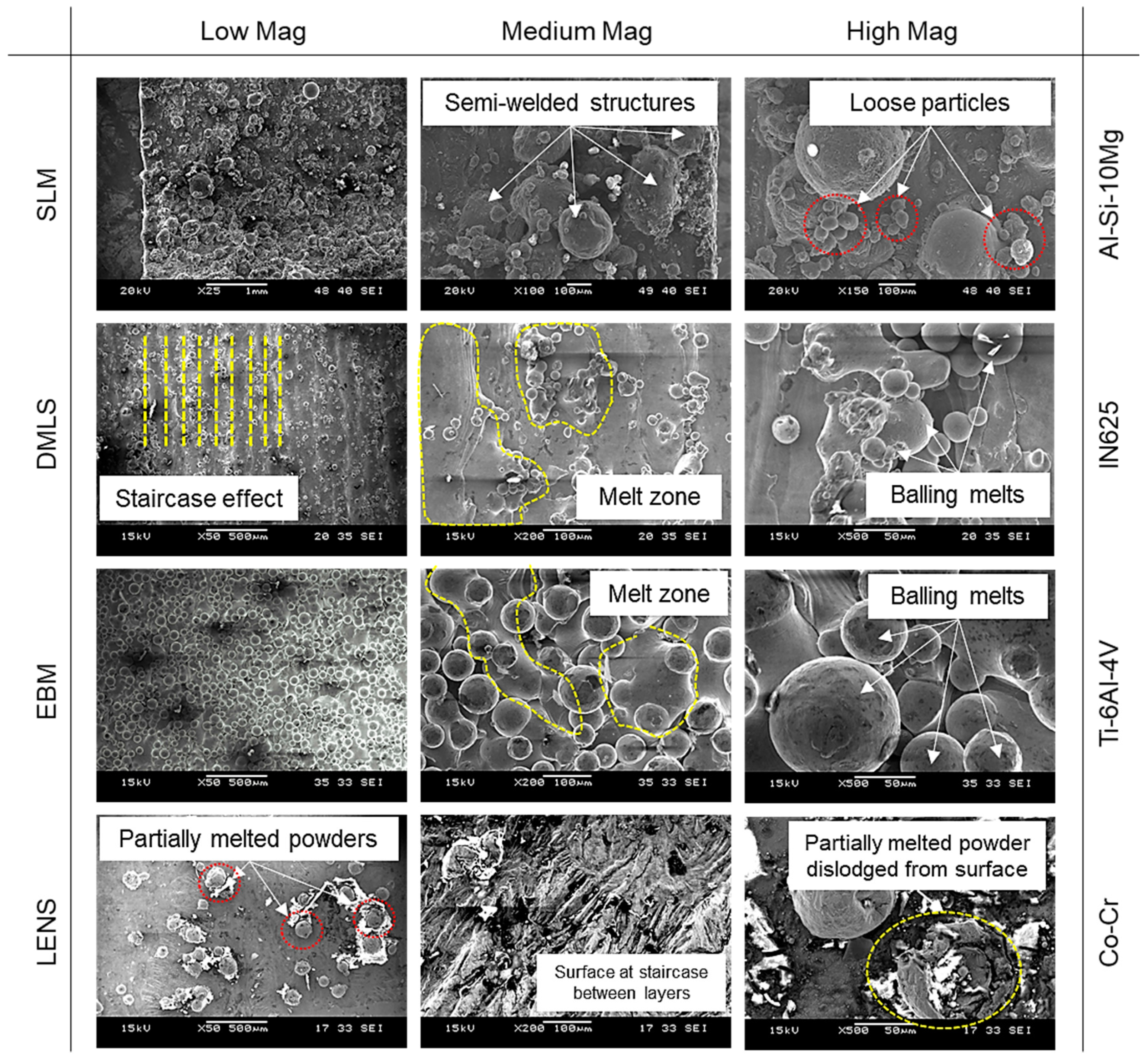
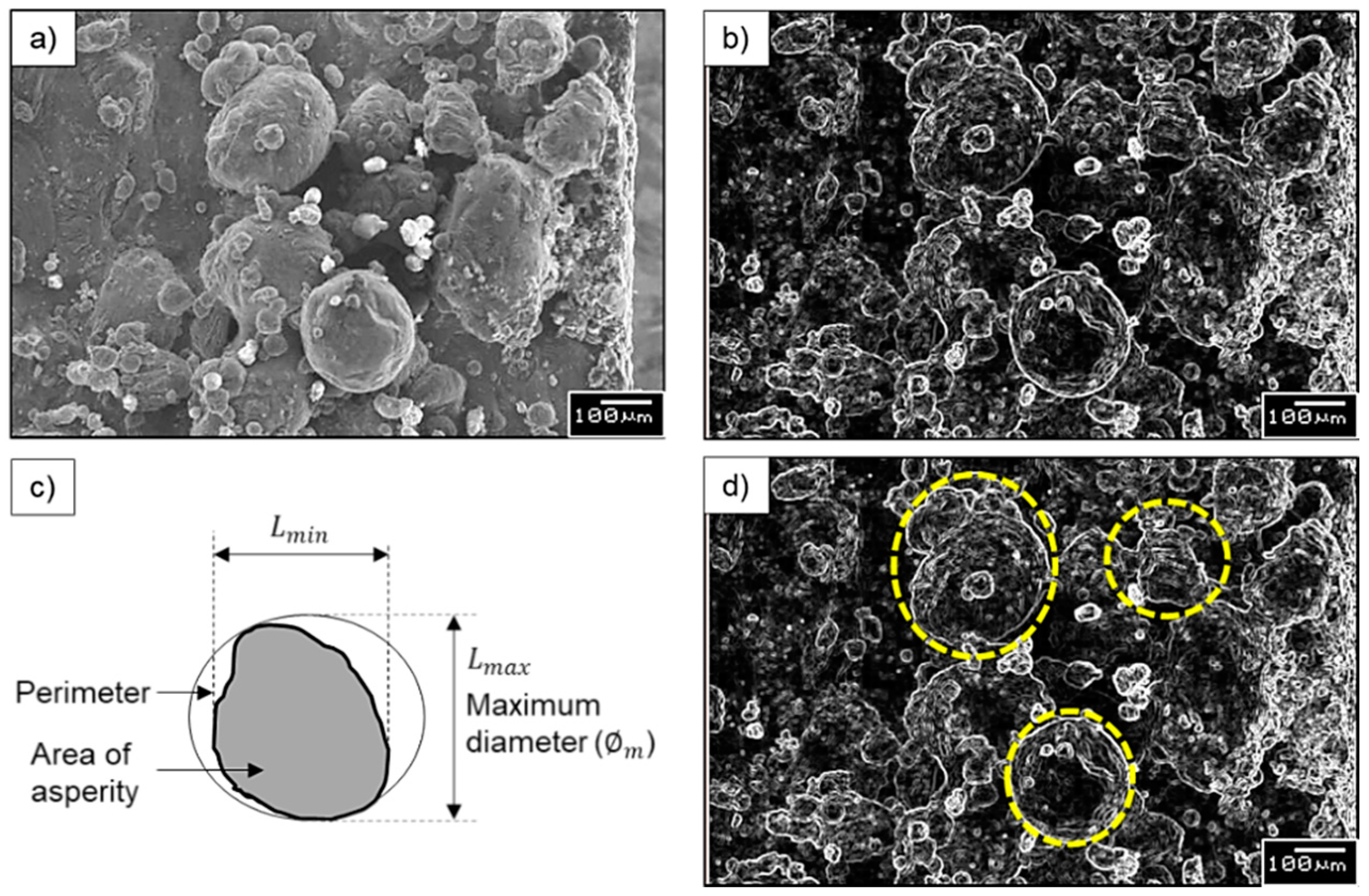
- Scanning electron microscope analysis provided a better understanding of the type of surface asperities present in an AM component.
- (2)
- The maximum diameter (φm) of each type of asperity can be used as a cut-off value for profile and areal surface texture characterization.
- (3)
- Changing the λc values used for profile surface texture leads to significant percentage deviations in the resulting profile surface texture parameters. Minimum deviations were noticed by reducing the evaluation length. Therefore, if the users experience insufficient sample length for measurement, it is recommended to maintain the λc suggested by ISO and compromise the evaluation length.
- (4)
- The length and width of the evaluation area for the areal surface texture analysis of AM surface should be five times the selected λc. If there is an insufficient area to measure, select the length and width of the area to be at least twice the λc selected.
- (5)
- To characterize the AM surface texture, smaller measurement areas (2 mm × 2 mm or even less, but not below the size of large irregularities present) are sufficient.
- (6)
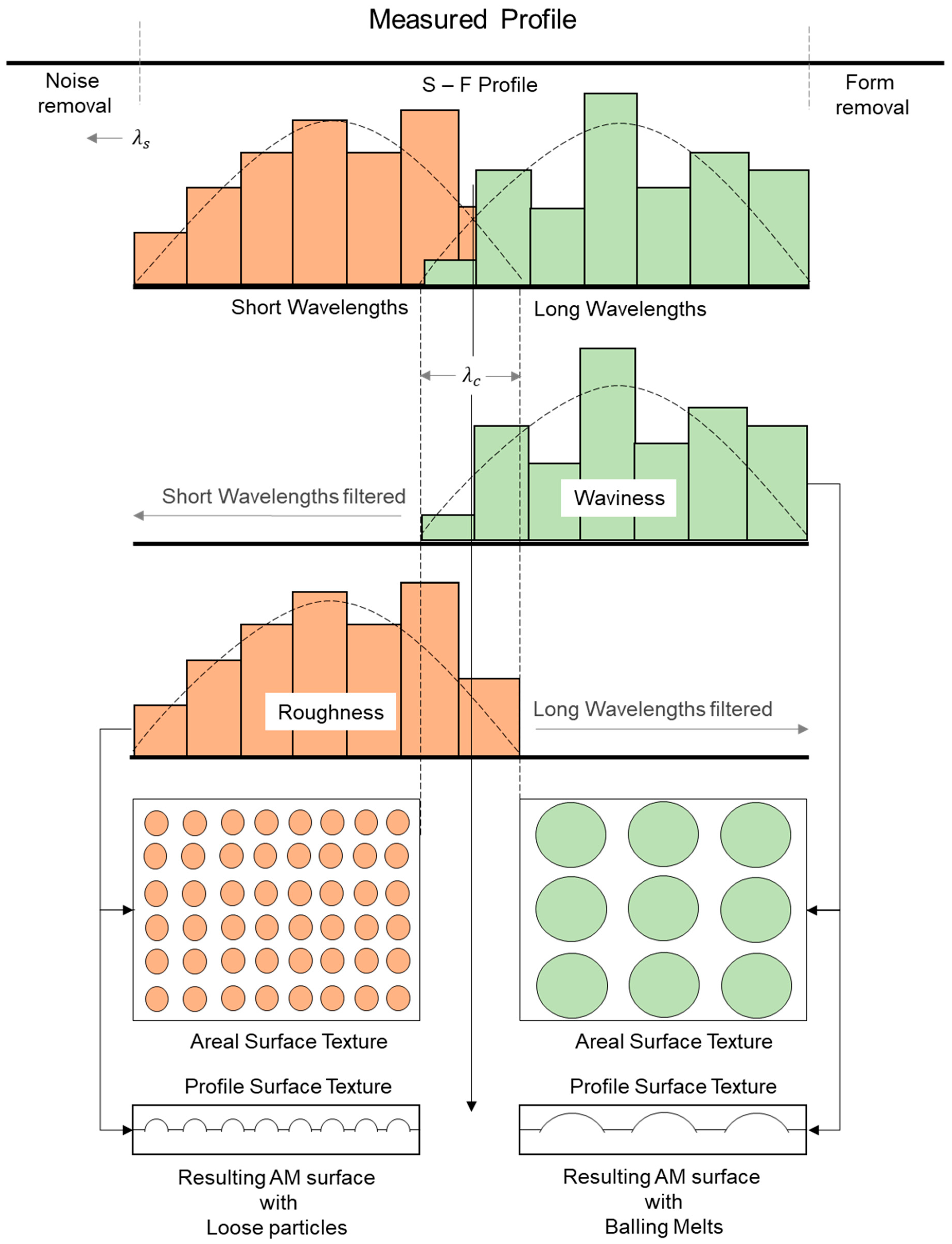
- By measuring the size of asperities present on the surface and applying them as λc, it is possible to analyze the surface texture from short wavelengths (loose particles, partially melted particles) and long wavelengths (balling melts, semi-welded structures, and staircase effect) separately.
Author Contributions
Funding
Acknowledgments
Conflicts of Interest
Nomenclature
| Profile Surface Texture Parameters | General Terms | ||
| Ra | Arithmetic mean deviation of the assessed profile | φm | Maximum diameter |
| Rq | Root mean square deviation of the assessed profile | SEM | Scanning Electron Microscope |
| Rz | Maximum height of the profile | DMLS | Direct Metal Laser Sintering |
| λc | Cut-off wavelength | SLM | Selective Laser Melting |
| ln | Evaluation length | EBM | Electron Beam Melting |
| lt | Transverse length | LENS | Laser Engineered Net Shaping |
| Vs | Stylus velocity | AM | Additive Manufacturing |
| Spre | Stylus pre-travel length | ||
| Spost | Stylus post-travel length | ||
| Areal Surface Texture Parameters | |||
| Sa | Arithmetical mean height of the scale limited surface | ||
| Sz | Maximum height of the scale-limited surface | ||
References
- Gao, W.; Zhang, Y.; Ramanujan, D.; Ramani, K.; Chen, Y.; Williams, C.B.; Wang, C.C.L.; Shin, Y.C.; Zhang, S.; Zavattieri, P.D. The status, challenges, and future of additive manufacturing in engineering. Comput. Aided Des. 2015, 69, 65–89. [Google Scholar] [CrossRef]
- Tofail, S.A.M.; Koumoulos, E.P.; Bandyopadhyay, A.; Bose, S.; O’Donoghue, L.; Charitidis, C. Additive manufacturing: Scientific and technological challenges, market uptake and opportunities. Mater. Today 2018, 21, 22–37. [Google Scholar] [CrossRef]
- Lee, J.-Y.; Nagalingam, A.P.; Yeo, S.H. A review on the state-of-the-art of surface finishing processes and related ISO/ASTM standards for metal additive manufactured components. Virtual Phys. Prototyp. 2021, 16, 68–96. [Google Scholar] [CrossRef]
- Thompson, A.; Senin, N.; Maskery, I.; Körner, L.; Lawes, S.; Leach, R. Internal surface measurement of metal powder bed fusion parts. Addit. Manuf. 2018, 20, 126–133. [Google Scholar] [CrossRef]
- Grimm, T.; Wiora, G.; Witt, G. Characterization of typical surface effects in additive manufacturing with confocal microscopy. Surf. Topogr. Metrol. Prop. 2015, 3, 014001. [Google Scholar] [CrossRef]
- Jamshidinia, M.; Kovacevic, R. The influence of heat accumulation on the surface roughness in powder-bed additive manufacturing. Surf. Topogr. Metrol. Prop. 2015, 3, 014003. [Google Scholar] [CrossRef]
- Triantaphyllou, A.; Giusca, C.L.; Macaulay, G.D.; Roerig, F.; Hoebel, M.; Leach, R.K.; Tomita, B.; Milne, K.A. Surface texture measurement for additive manufacturing. Surf. Topogr. Metrol. Prop. 2015, 3. [Google Scholar] [CrossRef]
- Pyka, G.; Kerckhofs, G.; Papantoniou, I.; Speirs, M.; Schrooten, J.; Wevers, M. Surface Roughness and Morphology Customization of Additive Manufactured Open Porous Ti6Al4V Structures. Materials 2013, 6, 4737. [Google Scholar] [CrossRef] [PubMed]
- Olakanmi, E.O. Selective laser sintering/melting (SLS/SLM) of pure Al, Al–Mg, and Al–Si powders: Effect of processing conditions and powder properties. J. Mater. Process. Technol. 2013, 213, 1387–1405. [Google Scholar] [CrossRef]
- Yasa, E.; Poyraz, O.; Solakoglu, E.U.; Akbulut, G.; Oren, S. A Study on the Stair Stepping Effect in Direct Metal Laser Sintering of a Nickel-based Superalloy. Procedia CIRP 2016, 45, 175–178. [Google Scholar] [CrossRef]
- Gu, D.; Dai, D.; Chen, W.; Chen, H. Selective Laser Melting Additive Manufacturing of Hard-to-Process Tungsten-Based Alloy Parts With Novel Crystalline Growth Morphology and Enhanced Performance. J. Manuf. Sci. Eng. 2016, 138. [Google Scholar] [CrossRef]
- ISO 4288 BE. BS EN ISO 4288. Geometric Product Specification (GPS): Surface Texture: Profile Method: Rules and Procedures for the Assessment Ofsurface Texture; British Standards Institute: London, UK, 1988. [Google Scholar]
- ISO 25178-3 BE. BS EN ISO 25178-3. Geometrical Product Specifications(GPS): Surface Texture: Areal: Part 3: Specification Operators; British Standards Institute: London, UK, 2012. [Google Scholar]
- ISO 25178-2 BE. BS EN ISO 25178-2. Geometrical Product Specifications(GPS): Surface Texture: Areal 2: Terms, Definitions and Surface Texture Parameters; British Standards Institute: London, UK, 2012. [Google Scholar]
- Heinl, M.; Greiner, S.; Wudy, K.; Pobel, C.; Rasch, M.; Huber, F.; Papke, T.; Merklein, M.; Schmidt, M.; Körner, C.; et al. Measuring procedures for surface evaluation of additively manufactured powder bed-based polymer and metal parts. Meas. Sci. Technol. 2020, 31, 095202. [Google Scholar] [CrossRef]
- Nagalingam, A.P.; Yuvaraj, H.K.; Santhanam, V.; Yeo, S.H. Multiphase hydrodynamic flow finishing for surface integrity enhancement of additive manufactured internal channels. J. Mater. Process. Technol. 2020, 283, 116692. [Google Scholar] [CrossRef]
- Nagalingam, A.P.; Lee, J.-Y.; Yeo, S.H. Multi-jet hydrodynamic surface finishing and X-ray computed tomography (X-CT) inspection of laser powder bed fused Inconel 625 fuel injection/spray nozzles. J. Mater. Process. Technol. 2021, 291, 117018. [Google Scholar] [CrossRef]
- Nagalingam, A.P.; Yeo, S.H. Surface finishing of additively manufactured Inconel 625 complex internal channels: A case study using a multi-jet hydrodynamic approach. Addit. Manuf. 2020, 36, 101428. [Google Scholar] [CrossRef]
- Mumtaz, K.; Hopkinson, N. Top surface and side roughness of Inconel 625 parts processed using selective laser melting. Rapid Prototyp. J. 2009, 15, 96–103. [Google Scholar] [CrossRef]
- Fox, J.C.; Moylan, S.P.; Lane, B.M. Effect of Process Parameters on the Surface Roughness of Overhanging Structures in Laser Powder Bed Fusion Additive Manufacturing. Procedia CIRP 2016, 45, 131–134. [Google Scholar] [CrossRef]
- Nagalingam, A.P.; Yeo, S.H. Controlled hydrodynamic cavitation erosion with abrasive particles for internal surface modification of additive manufactured components. Wear 2018, 414–415, 89–110. [Google Scholar] [CrossRef]
- Cabanettes, F.; Joubert, A.; Chardon, G.; Dumas, V.; Rech, J.; Grosjean, C.; Dimkovski, Z. Topography of as built surfaces generated in metal additive manufacturing: A multi scale analysis from form to roughness. Precis. Eng. 2018, 52, 249–265. [Google Scholar] [CrossRef]
- Todhunter, L.D.; Leach, R.K.; Lawes, S.D.A.; Blateyron, F. Industrial survey of ISO surface texture parameters. CIRP J. Manuf. Sci. Technol. 2017, 19, 84–92. [Google Scholar] [CrossRef]
- ISO 4287 BE. BS EN ISO 4287. Geometrical Product Specification (GPS): Surface Texture: Profile Method: Terms, Definitions and Surface Texture Parameters; British Standards Institute: London, UK, 2000. [Google Scholar]
- Muralikrishnan, B.; Raja, J. Chapter-5, Computational Surface and Roundness Metrology; Springer: London, UK, 2008. [Google Scholar]


| AM Technique | Material | Process Parameters | Post-Processing Technique |
|---|---|---|---|
| SLM | Al-Si-10Mg | Power: 200 W Layer thickness: 25 µm Powder size: 10 µm H:15 × W:15 × T:3 mm | NIL |
| DMLS | IN625 | Power: 200 W Layer thickness: 50 µm Powder size: 10–55 µm H:25 × W:25 × T:3 mm | Heat-treated (1 h; 870 °C) |
| EBM | Ti-6Al-4V | Power: 750 W Layer thickness: 50 µm Powder size: 25–50 µm H:25 × W:25 × T:3 mm | Heat-treated (1 h; 930 °C) |
| LENS | Co-Cr alloy | Power: 1000 W Layer thickness: 250 µm Powder size: 25–100 µm H:15 × W:15 × T:3 mm | NIL |
| Asperity Type | Loose Particles | Partial Melts | Balling Melts/Semi-Welds |
|---|---|---|---|
| Technique | Arithmetic Mean ± SD (µm) | ||
| SLM | 17.17 ± 4.11 | 135.75 ± 22.24 | 283.85 ± 53.10 |
| DMLS | 20.26 ± 6.74 | 66.11 ± 16.51 | 119.88 ± 17.35 |
| EBM | NA | NA | 78.10 ± 14.69 |
| LENS | NA | 86.54 ± 11.14 | NA |
| Profile Surface Texture Parameters | Ra | Rq | Rz | |
|---|---|---|---|---|
| Technique | ΛC/ln (mm) | Arithmetic Mean ± SD (µm) | ||
| SLM | 2.5/12.5 | 16.24 ± 1.40 | 23.31 ± 1.88 | 123.24 ± 9.23 |
| DMLS | 2.5/12.5 | 6.94 ± 0.24 | 9.29 ± 0.67 | 54.32 ± 5.69 |
| EBM | 2.5/12.5 | 20.48 ± 0.64 | 25.46 ± 0.80 | 120.63 ± 6.67 |
| LENS | 2.5/12.5 | 11.48 ± 0.69 | 14.77 ± 0.81 | 65.58 ± 9.82 |
| S. No | Profile Surface Texture Parameters | Ra | Rq | Rz | |
|---|---|---|---|---|---|
| Technique | ΛC/Ln Mm | Arithmetic Mean ± SD (µm) | |||
| 1 | SLM | 0.025/0.125 | 0.62 ± 0.28 | 0.75 ± 0.31 | 2.41 ± 1.00 |
| 2 | 0.08/0.4 | 3.08 ± 0.62 | 4.05 ± 0.87 | 14.86 ± 4.28 | |
| 3 | 0.25/1.25 | 9.05 ± 2.54 | 11.22 ± 3.09 | 42.12 ± 10.71 | |
| 4 | 0.8/4 | 11.64 ± 1.71 | 0.82 ± 2.56 | 61.4 ± 13.31 | |
| 5 | 0.8/12.5 | 14.65 ± 1.51 | 19.65 ± 2.50 | 160.50 ± 20.17 | |
| 6 | 2.5/4 | 19.44 ± 3.08 | 29.09 ± 4.95 | 156.39 ± 31.45 | |
| 7 | 8/12.5 | NA | NA | NA | |
| 1 | DMLS | 0.025/0.125 | 0.36 ± 0.20 | 0.47 ± 0.25 | 1.61 ± 0.89 |
| 2 | 0.08/0.4 | 1.25 ± 0.34 | 1.56 ± 0.42 | 4.56 ± 2.37 | |
| 3 | 0.25/1.25 | 3.08 ± 0.57 | 3.97 ± 0.84 | 16.02 ± 3.19 | |
| 4 | 0.8/4 | 6.19 ± 0.68 | 7.98 ± 0.97 | 38.12 ± 4.95 | |
| 5 | 0.8/12.5 | 5.78 ± 0.60 | 7.95 ± 0.94 | 69.45 ± 9.68 | |
| 6 | 2.5/4 | 6.85 ± 0.71 | 9.22 ± 1.62 | 60.51 ± 17.62 | |
| 7 | 8/12.5 | 7.32 ± 0.39 | 9.71 ± 0.55 | 80.88 ± 11.67 | |
| 1 | EBM | 0.025/0.125 | 0.33 ± 0.06 | 0.42 ± 0.10 | 1.36 ± 0.27 |
| 2 | 0.08/0.4 | 1.93 ± 0.38 | 2.44 ± 0.36 | 8.85 ± 1.05 | |
| 3 | 0.25/1.25 | 7.40 ± 1.41 | 8.95 ± 1.50 | 34.30 ± 6.12 | |
| 4 | 0.8/4 | 15.74 ± 0.67 | 19.06 ± 0.58 | 83.25 ± 4.68 | |
| 5 | 0.8/12.5 | 16.68 ± 0.62 | 20.65 ± 0.69 | 126.29 ± 8.08 | |
| 6 | 2.5/4 | 20.34 ± 1.37 | 25.84 ± 1.48 | 138.55 ± 9.11 | |
| 7 | 8/12.5 | 22.28 ± 0.63 | 27.88 ± 0.80 | 173.75 ± 16.61 | |
| 1 | LENS | 0.025/0.125 | 0.095 ± 0.02 | 0.131 ± 0.04 | 0.396 ± 0.13 |
| 2 | 0.08/0.4 | 0.44 ± 0.14 | 0.58 ± 0.18 | 2.16 ± 0.95 | |
| 3 | 0.25/1.25 | 4.83 ± 4.29 | 5.98 ± 5.24 | 22.74 ± 19.13 | |
| 4 | 0.8/4 | 4.38 ± 0.72 | 5.76 ± 0.94 | 24.97 ± 4.25 | |
| 5 | 0.8/12.5 | 4.22 ± 0.85 | 9.80 ± 1.27 | 89.79 ± 17.11 | |
| 6 | 2.5/4 | 11.91 ± 2.15 | 18.03 ± 1.71 | 84.20 ± 26.36 | |
| 7 | 8/12.5 | NA | NA | NA | |
| S. No | Technique | λc (mm) | Sa (µm) | Sz (µm) | ||
|---|---|---|---|---|---|---|
| Arithmetic Mean | ||||||
| Waviness | Roughness | Waviness | Roughness | |||
| 1 | SLM | 0.025 | 22.9 | 1.25 | 212 | 58.9 |
| 2 | 0.08 | 20.9 | 4.89 | 143 | 157 | |
| 3 | 0.25 | 15.7 | 11.7 | 50.6 | 210 | |
| 4 | 0.8 | 6.78 | 18 | 0 | 162 | |
| 1 | DMLS | 0.025 | 5.96 | 0.576 | 61.7 | 16.2 |
| 2 | 0.08 | 4.93 | 2.47 | 31.7 | 33.3 | |
| 3 | 0.25 | 3.52 | 4.6 | 12.8 | 47.8 | |
| 4 | 0.8 | 1.99 | 5.71 | 0 | 58.6 | |
| 1 | EBM | 0.025 | 20.2 | 0.767 | 128 | 27.5 |
| 2 | 0.08 | 18.5 | 4.01 | 102 | 59 | |
| 3 | 0.25 | 13.3 | 11.6 | 39.9 | 99.4 | |
| 4 | 0.8 | 5.71 | 18.9 | 0 | 145 | |
| 1 | LENS | 0.025 | 19.1 | 0.226 | 125 | 7.73 |
| 2 | 0.08 | 18.8 | 1.22 | 108 | 27 | |
| 3 | 0.25 | 17.8 | 5.24 | 0 | 80.3 | |
| 4 | 0.8 | 12.7 | 13.4 | 0 | 127 | |
| Profile Surface Texture Parameter | Ra | Rq | Rz | |
|---|---|---|---|---|
| Technique | λc/ln mm | Arithmetic Mean ± SD (µm) | ||
| DMLS (ISO framework) | 2.5/12.5 | 6.94 ± 0.24 | 9.29 ± 0.67 | 54.32 ± 5.69 |
| DMLS (investigative framework) | 0.08/0.4 | 1.25 ± 0.34 | 1.56 ± 0.42 | 4.56 ± 2.37 |
| 0.25/1.25 | 3.08 ± 0.57 | 3.97 ± 0.84 | 16.02 ± 3.19 | |
Publisher’s Note: MDPI stays neutral with regard to jurisdictional claims in published maps and institutional affiliations. |
© 2021 by the authors. Licensee MDPI, Basel, Switzerland. This article is an open access article distributed under the terms and conditions of the Creative Commons Attribution (CC BY) license (https://creativecommons.org/licenses/by/4.0/).
Share and Cite
Nagalingam, A.P.; Vohra, M.S.; Kapur, P.; Yeo, S.H. Effect of Cut-Off, Evaluation Length, and Measurement Area in Profile and Areal Surface Texture Characterization of As-Built Metal Additive Manufactured Components. Appl. Sci. 2021, 11, 5089. https://doi.org/10.3390/app11115089
Nagalingam AP, Vohra MS, Kapur P, Yeo SH. Effect of Cut-Off, Evaluation Length, and Measurement Area in Profile and Areal Surface Texture Characterization of As-Built Metal Additive Manufactured Components. Applied Sciences. 2021; 11(11):5089. https://doi.org/10.3390/app11115089
Chicago/Turabian StyleNagalingam, Arun Prasanth, Moiz Sabbir Vohra, Pulkit Kapur, and Swee Hock Yeo. 2021. "Effect of Cut-Off, Evaluation Length, and Measurement Area in Profile and Areal Surface Texture Characterization of As-Built Metal Additive Manufactured Components" Applied Sciences 11, no. 11: 5089. https://doi.org/10.3390/app11115089
APA StyleNagalingam, A. P., Vohra, M. S., Kapur, P., & Yeo, S. H. (2021). Effect of Cut-Off, Evaluation Length, and Measurement Area in Profile and Areal Surface Texture Characterization of As-Built Metal Additive Manufactured Components. Applied Sciences, 11(11), 5089. https://doi.org/10.3390/app11115089