
Roto-Translational Control of Spacecraft in Low Earth Orbit Using Environmental Forces and Torques


Abstract
1. Introduction
- Design and verification through numerical simulation of an adaptive controller capable of simultaneously achieving three-axis attitude stabilization and in-plane relative maneuvering.
- Compensation for physical and environmental uncertainties such as drag/lift coefficients, atmospheric density and CoM location.
- Guaranteed ultimately bounded stability through Lyapunov-based analysis in the presence of uncertainties and perturbations.
2. Spacecraft Dynamics
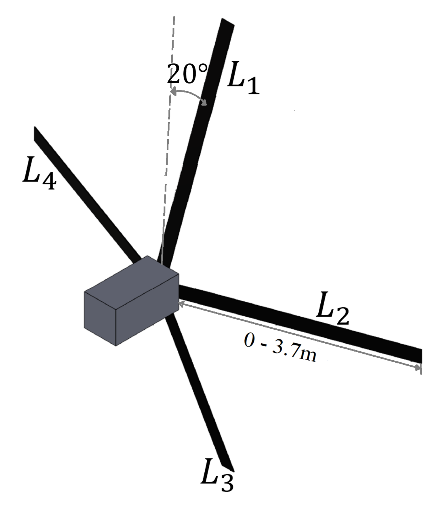
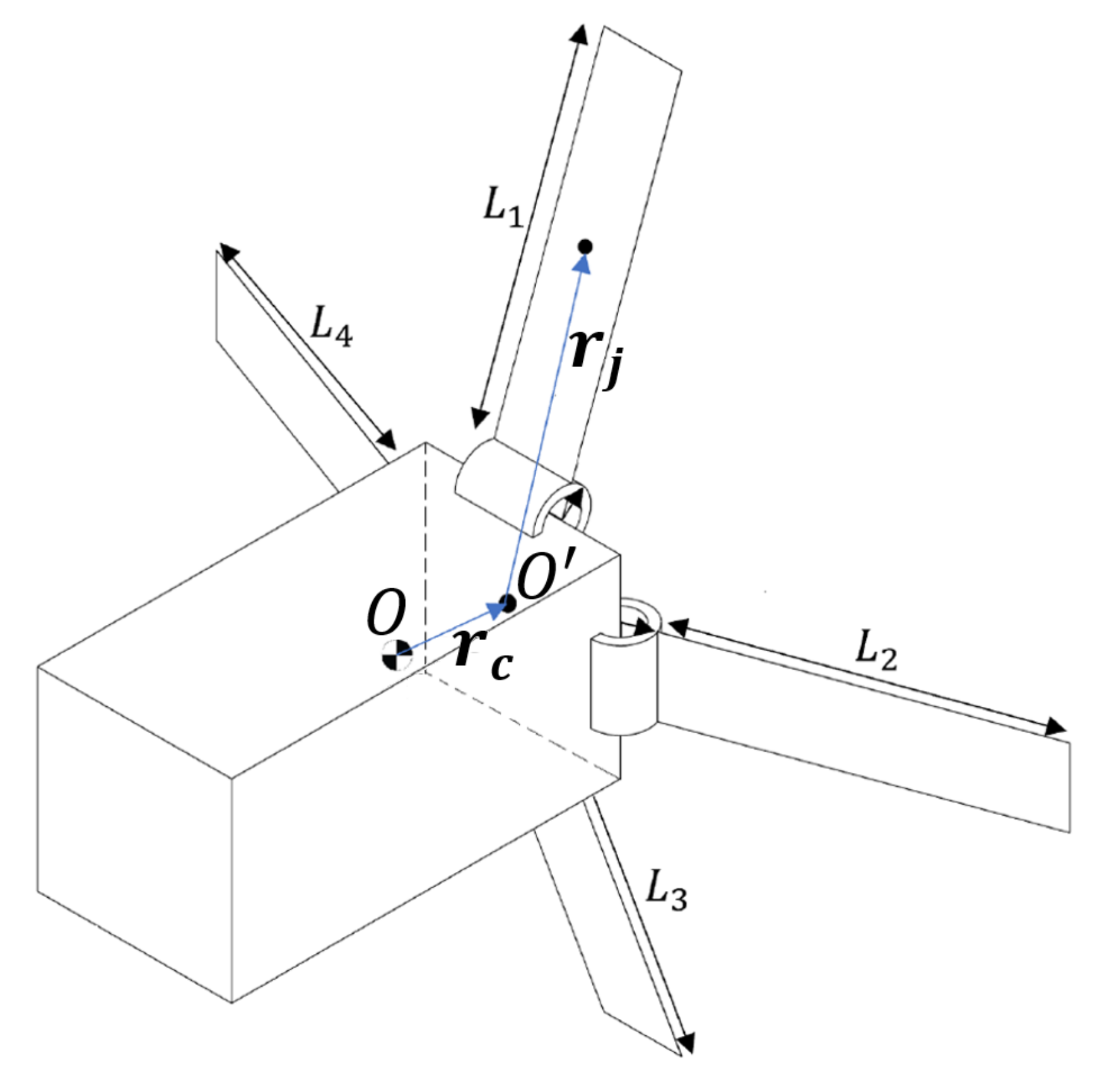
2.1. The Drag Maneuvering Device (DMD)
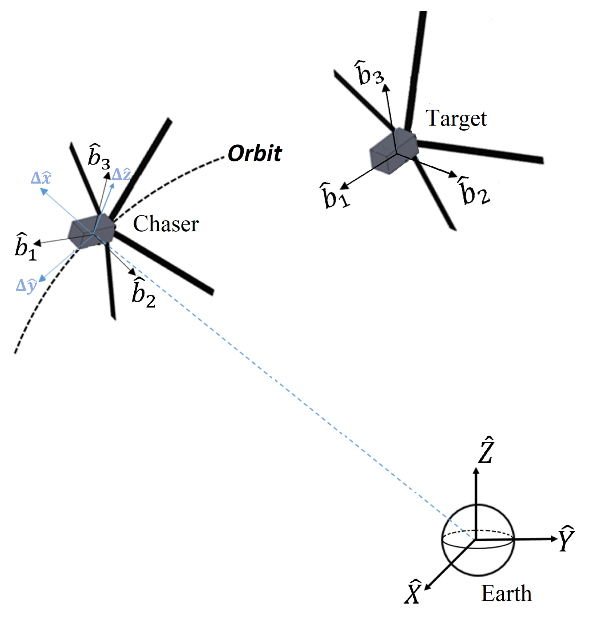
2.2. Coordinate Systems
2.2.1. Earth-Centered Inertial Reference Frame
2.2.2. Local Vertical-Local Horizontal
2.2.3. Body Reference Frame
2.3. Translational Dynamics
2.4. Attitude Dynamics
2.5. Aerodynamic Forces and Torques
2.6. Gravity Gradient Torque
3. Controller Design
3.1. Control Objective
3.2. Control Development
3.3. Stability Analysis
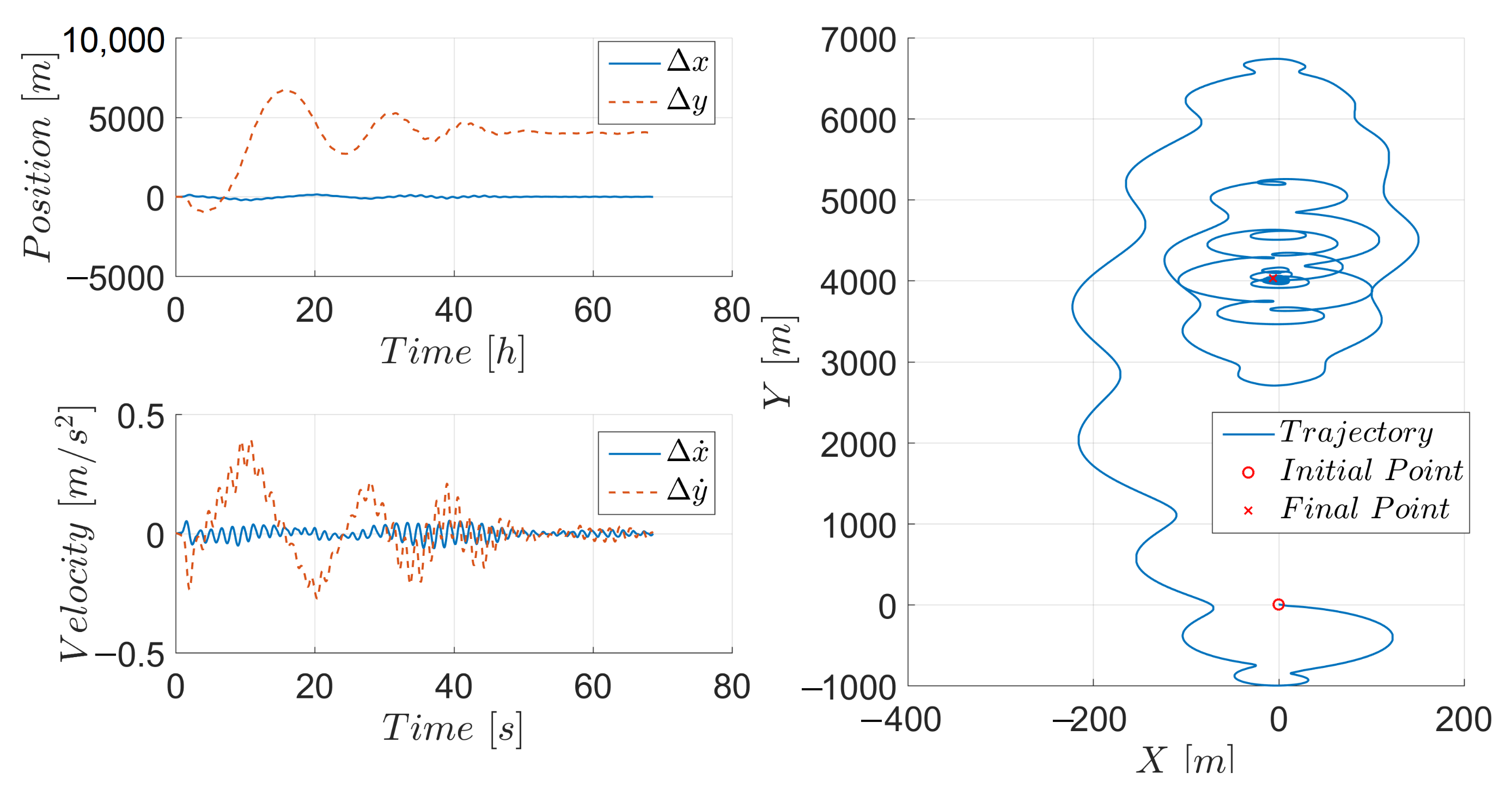
4. Simulation Results and Discussion
5. Conclusions
Author Contributions
Funding
Conflicts of Interest
References
- Heidt, H.; Puig-Suari, J.; Moore, A.; Nakasuka, S.; Twiggs, R. CubeSat: A new generation of picosatellite for education and industry low-cost space experimentation. In Proceedings of the 14TH Annual/USU Conference on Small Satellites, Logan, UT, USA, 21–24 August 2000. [Google Scholar]
- Cappelletti, C.; Battistini, S.; Malphrus, B. CubeSat Handbook. In Mission Design to Operations; Academic Press: New York, NY, USA, 2020. [Google Scholar]
- Poghosyan, A.; Golkar, A. CubeSat evolution: Analyzing CubeSat capabilities for conducting science missions. Prog. Aerosp. Sci. 2017, 88, 59–83. [Google Scholar] [CrossRef]
- Schoolcraft, J.; Klesh, A.; Werne, T. MarCO: Interplanetary Mission Development on a CubeSat Scale. In Proceedings of the AIAA SpaceOps 2016 Conference, Daejeon, Korea, 16–20 May 2016. [Google Scholar] [CrossRef]
- Leonard, C.L.; Hollister, W.M.; Bergman, E.V. Orbital formation keeping with differential drag. J. Guid. Control Dyn. 1989, 12, 108–113. [Google Scholar] [CrossRef]
- Bevilacqua, R.; Romano, M. Rendezvous maneuvers of multiple spacecraft by differential drag under J2 perturbation. J. Guid. Control Dyn. 2008, 31, 1595–1607. [Google Scholar] [CrossRef]
- Horlsey, M.; Nikolaev, S.; Pertica, A. Rendezvous maneuvers of small spacecraft using differential lift and drag. J. Guid. Control Dyn. 2011, 36, 445–453. [Google Scholar]
- Perez, D.; Bevilacqua, R. Differential drag spacecraft rendezvous using an adaptive Lyapunov control strategy. Acta Astronaut. 2012, 83, 196–207. [Google Scholar] [CrossRef]
- Ivanov, D.; Kushniruk, M.; Ovchinnikov, M. Study of satellite formation flying control using differential lift and drag. Acta Astronaut. 2018, 152, 88–100. [Google Scholar] [CrossRef]
- Varma, S.; Kumar, K.D. Multiple satellite formation flying using differential aerodynamic drag. J. Spacecr. Rocket. 2012, 49, 325–336. [Google Scholar] [CrossRef]
- Riano-Rios, C.; Bevilacqua, R.; Dixon, W.E. Relative maneuvering for multiple spacecraft via differential drag using lqr and constrained least squares. In Proceedings of the 29th AAS/AIAA Space Flight Mechanics Meeting, Ka’anapali, HI, USA, 13–17 January 2019. [Google Scholar]
- Maclay, T.D.; Tuttle, C. Satellite station keeping of the orbcomm constellation via active control of atmospheric drag: Operations, constraints and performance. Adv. Astronaut. Sci. 2005, 120, 763–774. [Google Scholar]
- Foster, C.; Mason, J.; Vittaldev, V.; Beukelaers, L.; Stepan, L.; Zimmerman, R. Constellation phasing with differential drag on planet labs satellites. J. Spacecr. Rocket. 2018, 55, 473–483. [Google Scholar] [CrossRef]
- Omar, S.; Riano-Rios, C.; Bevilacqua, R. Semi-passive three axis attitude stabilization for earth observation satellites using the drag maneuvering device. In Proceedings of the 12th Symposium on Small Satellite for Earth Observation, Berlin, Germany, 6–10 May 2019. [Google Scholar]
- Sun, R.; Riano-Rios, C.; Bevilacqua, R.; Fitz-Coy, N.G.; Dixon, W.E. Cubesat adaptive attitude control with uncertain drag coefficient and atmospheric density. J. Guid. Control Dyn. 2021, 44, 379–389. [Google Scholar] [CrossRef]
- Fedele, A.; Carannante, S.; Grassi, M.; Savino, R. Aerodynamic control system for a deployable re-entry capsule. Acta Astronaut. 2021, 181, 707–716. [Google Scholar] [CrossRef]
- Omar, S.R.; Bevilacqua, R. Guidance, navigation, and control solutions for spacecraft re-entry point targeting using aerodynamic drag. Acta Astronaut. 2019, 155, 389–405. [Google Scholar] [CrossRef]
- Fedele, A.; Omar, S.; Cantoni, S.; Savino, R.; Bevilacqua, R. Precise Re-Entry and Landing of Propellantless Low Earth Orbit Spacecraft. In Proceedings of the 2nd IAA Conference on Space Situational Awareness (ICSSA), Washington, DC, USA, 14–16 January 2020. [Google Scholar]
- Fedele, A.; Gardi, R.; Pezzella, G. Aerothermodynamics and thermal design for on-ground and in-flight testing of a deployable heat shield capsule. CEAS Space J. 2020, 12, 411–428. [Google Scholar] [CrossRef]
- Fedele, A.; Mungiguerra, S. Aerodynamics and flight mechanics activities for a suborbital flight test of a deployable heat shield capsule. Acta Astronaut. 2018, 151, 324–333. [Google Scholar] [CrossRef]
- Guglielmo, D.; Omar, S.; Bevilacqua, R.; Fineberg, L.; Treptow, J.; Poffenberger, B.; Johnson, Y. Drag deorbit device: A new standard reentry actuator for CubeSats. J. Spacecr. Rocket. 2019, 56, 129–145. [Google Scholar] [CrossRef]
- The CubeSat Program. CubeSat Design Specification Rev. 13; The CubeSat Program, CalPoly: San Luis Obispo, CA, USA, 2015. [Google Scholar]
- Schweighart, S.A.; Sedwick, R.J. High-Fidelity Linearized J2 Model for Satellite Formation Flight. J. Guid. Contro Dyn. 2002, 25, 1073–1080. [Google Scholar] [CrossRef]
- Hughes, P.C. Spacecraft Attitude Dynamics. In Dover Books on Aeronautical Engineering; Dover Publications: New York, NY, USA, 2012. [Google Scholar]
- Schaub, H.; Junkins, J.L. Analytical Mechanics of Space Systems; AIAA Education Series: Reston, VA, USA, 2014. [Google Scholar]
- Picone, J.M.; Hedin, A.E.; Drob, D.P.; Aikin, A.C. NRLMSISE-00 empirical model of the atmosphere: Statistical comparisons and scientific issues. J. Geophys. Res. 2002, 107, 15-1–15-16. [Google Scholar] [CrossRef]
- Montenbruck, O.; Gill, E. Satellite Orbits: Models, Methods and Applications; Springer: Berlin, Germany, 2000. [Google Scholar]
- Riano-Rios, C.; Bevilacqua, R.; Dixon, W.E. Adaptive control for differential drag-based rendezvous maneuvers with an unknown target. Acta Astronaut. 2021, 181, 733–740. [Google Scholar] [CrossRef]
- Riano-Rios, C.; Bevilacqua, R.; Dixon, W.E. Differential drag-based multiple spacecraft maneuvering and on-line parameter estimation using integral concurrent learning. Acta Astronaut. 2020, 174, 189–203. [Google Scholar] [CrossRef]
- Riano-Rios, C.; Sun, R.; Bevilacqua, R.; Dixon, W.E. Aerodynamic and gravity gradient based attitude control for CubeSats in the presence of environmental and spacecraft uncertainties. Acta Astronaut. 2021, 180, 439–450. [Google Scholar] [CrossRef]
- Cai, Z.; de Queiroz, M.S.; Dawson, D.M. A sufficiently smooth projection operator. IEEE Trans. Automat. Control 2006, 51, 135–139. [Google Scholar] [CrossRef]
- Khalil, H.K. Nonlinear Systems, 3rd ed.; Prentice Hall: Upper Saddle River, NJ, USA, 2002. [Google Scholar]
- Pilinski, M. Dynamic Gas-Surface Interaction Modeling for Satellite Aerodynamic Computations. Ph.D. Thesis, University of Colorado Boulder, Boulder, CO, USA, 2011. [Google Scholar]


| [m] | [kg] | [m] | [m] |
|---|---|---|---|
| 0.2 | 3 | 0.5 | 0.01 |
| Parameter | Value |
|---|---|
| [deg] | 13.5 |
| [deg] | −12 |
| [deg] | 10 |
| [deg/s] | |
| [deg/s] | |
| [deg/s] |
| Parameter | Value |
|---|---|
| [deg] | −25 |
| [deg] | 0 |
| [deg] | 15 |
| [deg] | 30 |
| [deg] | 0 |
| [deg] | −10 |
| Parameter | Value |
|---|---|
| Semi-Major Axis [km] | 6778 |
| Eccentricity | 0 |
| Inclination [deg] | 51.94 |
| RAAN [deg] | 206.26 |
| Arg. of perigee [deg] | 201.07 |
| True Anomaly [deg] | 108.08 |
| Parameter | Value |
|---|---|
| 1 | |
| 3.2 | |
| Q | |
| R | 6 |
| Freq. Mode 1 | Freq. Mode 2 | Freq. Mode 3 | Freq. Mode 4 | Freq. Mode 5 |
|---|---|---|---|---|
| 0.1396 Hz | 0.1624 Hz | 0.2310 Hz | 0.4040 Hz | 0.6597Hz |
Publisher’s Note: MDPI stays neutral with regard to jurisdictional claims in published maps and institutional affiliations. |
© 2021 by the authors. Licensee MDPI, Basel, Switzerland. This article is an open access article distributed under the terms and conditions of the Creative Commons Attribution (CC BY) license (https://creativecommons.org/licenses/by/4.0/).
Share and Cite
Riano-Rios, C.; Fedele, A.; Bevilacqua, R. Roto-Translational Control of Spacecraft in Low Earth Orbit Using Environmental Forces and Torques. Appl. Sci. 2021, 11, 4606. https://doi.org/10.3390/app11104606
Riano-Rios C, Fedele A, Bevilacqua R. Roto-Translational Control of Spacecraft in Low Earth Orbit Using Environmental Forces and Torques. Applied Sciences. 2021; 11(10):4606. https://doi.org/10.3390/app11104606
Chicago/Turabian StyleRiano-Rios, Camilo, Alberto Fedele, and Riccardo Bevilacqua. 2021. "Roto-Translational Control of Spacecraft in Low Earth Orbit Using Environmental Forces and Torques" Applied Sciences 11, no. 10: 4606. https://doi.org/10.3390/app11104606
APA StyleRiano-Rios, C., Fedele, A., & Bevilacqua, R. (2021). Roto-Translational Control of Spacecraft in Low Earth Orbit Using Environmental Forces and Torques. Applied Sciences, 11(10), 4606. https://doi.org/10.3390/app11104606