Abstract
This study investigates the potential application of Stateflow (SF) to design an energy management strategy (EMS) for a renewable-based hybrid energy system (HES). The SF is an extended finite state machine; it provides a platform to design, model, and execute complex event-driven systems using an interactive graphical environment. The HES comprises photovoltaics (PV), energy storage units (ESU) and a diesel generator (Gen), integrated with the power grid that experiences a regular load shedding condition (scheduled power outages). The EMS optimizes the energy production and utilization during both modes of HES operation, i.e., grid-connected mode and the islanded mode. For islanded operation mode, a resilient power delivery is ensured when the system is subjected to intermittent renewable supply and grid vulnerability. The contributions of this paper are twofold: first is to propose an integrated framework of HES to address the problem of load shedding, and second is to design and implement a resilient EMS in the SF environment. The validation of the proposed EMS demonstrates its feasibility to serve the load for various operating scenarios. The latter include operations under seasonal variation, abnormal weather conditions, and different load shedding patterns. The simulation results reveal that the proposed EMS not only ensures uninterrupted power supply during load shedding but also reduces grid burden by maximizing the use of PV energy. In addition, the SF-based adopted methodology is envisaged to be a useful alternative to the popular design method using the conventional software tools, particularly for event-driven systems.
1. Introduction
Distributed power generation technologies are becoming popular to combat the problem of frequent outages. In addition to this, they minimize adverse environmental impacts, reduce or eliminate the losses and costs associated with the transmission and distribution lines, decrease the planning and construction time, and reduce the reliance on the grid. In this regard, various set-ups of renewable energy sources (RES) have been installed according to the localized availability of renewable energy. Among the RES, the PV power system is globally recognized as the most promising due to its abundance and environment-friendly nature. The PV system is simple to install, low in maintenance, quiet, and does not require fuel to sustain its operation [1]. However, weather-dependent variations and the intermittency of the sun have become a hindrance for PV to become a fully dependable distributed power generator. Under these circumstances, the integration of battery banks becomes essential to improve the reliability of such systems [2]. In most cases, the backup generators are also used to increase the availability and resiliency of the system [3]. These systems are called HES as they combine both renewable and non-renewable energy sources.
Furthermore, the innovative concept of hybridization capitalizes on the benefits of the conventional and non-conventional (RES) sources [4]. The HES can operate in standalone mode (for supplying electricity to remote areas) or in a grid-connected mode (for supplying electricity to communities where the grid is readily available) [5,6].
To achieve an efficient and stable operation of HES, an effective energy management system is needed. Its primary function is to manage the energy production and utilization such that uninterrupted power flow from various sources to the load is ensured. In addition, other objectives, such as reducing the system cost, optimizing the usage of the HES components, and maximizing the efficiency, may be set according to the localized requirements [7]. Several research works dedicated to energy management strategies of HES have been published, with a few of them focusing on ensuring the power balance and the demand satisfaction [6,7,8]. However, the control strategies for the grid-connected system differs from the off-grid system. Depending on the system configuration, the off-grid system needs to have sufficient storage capacity to handle power variations from the alternative energy sources [9]. The storage (battery, hydrogen) absorbs the transients and allows the power balance to be maintained by remaining between the minimum and maximum state of charge (SOC) limits. The diesel generator (if incorporated) works as a tertiary backup to operate in the worst-case scenarios. Such systems can be considered as microgrids with their own generation sources and loads, as well as power electronic interfaces to control voltage and frequency and ensure proper load sharing among its sources. Conversely, for the grid-connected system, there is no need for battery storage systems or their capacity can be smaller as the grid can be used as a system backup [9]. The grid, being the active part of the system, maintains the power balance by supplying or absorbing energy. Ideally, grid-connected configurations allow more flexibility and energy security than off-grid configurations. However, the system becomes more vulnerable if the grid is weak and subjected to load shedding—a condition whereby the utility disconnects the electricity supply to specific customers on a time-sharing basis. The load shedding is commonly used in countries or regions in which the supply of electricity is inadequate [10]. These scheduled disruptions can complicate the HES control because the system has to undergo frequent transitions between different operating modes to sustain the load demand. Adding to the complexity of the problem is coping with the intermittency of PV power, the need to maintain the level of the state of charge of the ESU within the acceptable limit, and to minimize the fuel consumption of the generators.
Despite many studies for the grid-connected system [6,11], limited research has been done on load shedding. For instance, the optimal power dispatch in solar assisted uninterruptible power supply systems for residential application is investigated in [10,12]. Both research works, however, focused toward the feasibility of the designed system in terms of costs. Furthermore, the energy management scheme is proposed for hospital buildings in Gaza that experience frequent grid outages [13]. Authors in this work consider the hypothetical scenarios of grid outage; further, their EMS did not analyze the performance of the system at nighttime, i.e., during the absence of PV power. Recently, another research work analyzed the control operation of a microgrid with a PV and diesel generator backup system under the time-of-use (TOU) tariff policy [8]. The case study was performed for a university campus in Kenya, and the performance of the proposed system was investigated under a grid black-out scenario. This work presents a good analysis of the instantaneous response of energy resources during a grid outage. However, in this control operation, the recurring scenario of load shedding is not analyzed. In addition, their design does not include the battery storage system; thus, the charging and discharging behavior during operation cannot be noticed.
The main objective of the above studies is to obtain uninterrupted continuity of the power supply, which is also the main aim of this work; however, the EMS introduced in this paper stands out from other studies as it considers an additional constraint in the form of actual load shedding schedule. The paper advances the EMS design by implementing the proposed control using SF, which has not been reported before. Modeling the EMS using SF has many advantages in terms of reducing the complexity and simplifying the control tasks, providing a better understanding of the HES operation, and increasing the ability to reconfigure operating conditions and accommodate new subsystems at any stage. Hence, it makes a good case study of how supply and demand might be balanced on an hour-by-hour basis and grid stability maintained by taking the benefit from the SFs’ inherent ability to simulate the event-driven system. The main contributions of this paper are twofold: first, the design of an integrated framework of HES to address the problem of load shedding, and second, the implementation of the EMS in the SF environment and observation of the resiliency of HES using annual data of an actual load shedding schedule and the weather profile (temperature, irradiance) of the studied location.
The paper is organized as follows. Section 2 introduces the architecture of the proposed HES used in the test case. It also outlines the hierarchical control objectives implemented through different levels in a hierarchy. Then, the main concepts pertaining to the SF are explained using a simple example. The implementation of the proposed EMS in an SF environment is explained in detail. The modeling methods and the specification of HES components, along with a description of location of the area, is described in Section 3. The case study is based on the load shedding condition imposed on a locality in the city of Quetta, Pakistan. The sun irradiance data are also obtained from the same area. Section 4 demonstrates the operation of HES based on several modes of operation, in an SF environment. Accordingly, the results and discussion part are presented in Section 5. Finally, Section 6 concludes the paper.
2. The HES Architecture and Modeling in Stateflow
In general, the HES operations are realized through different levels of control hierarchy [5,14,15]. The hierarchical structures can be classified into three levels: primary, secondary, and tertiary, as depicted in Figure 1. The primary control, which is the lowest level, is responsible for updating the values of the current, voltage, and frequency of the system. The most common example for HES is the V–I droop control [16]. On the other hand, the tertiary control (the highest level) is utilized to ensure optimal operation of the HES over a much longer term. Its fundamental role is to manage the energy flow among the sources of the HES and utility grid in order to achieve certain designed objectives, such as load scheduling, energy management, and optimization. The secondary level control is intermediate between the two. It mainly focuses on power flow coordination and restoration of the voltages of the dc bus to the nominal value. In addition to the control tasks, it must be emphasized that in the literature, the expressions “power management” and the “energy management” are distinct from each other in terms of time scales [5]. The key parameters in primary control are the instantaneous values of the electrical parameters. To achieve a meaningful response, its control strategies require very small control sampling time, i.e., from tens of micro to milliseconds [17]. For the tertiary level, since the evaluation of the objectives is long-term, the typical sampling time can be in minutes or hours. The scope of this work is oriented towards tertiary control. Various research works dedicated to tertiary control are reported in [7,18,19].
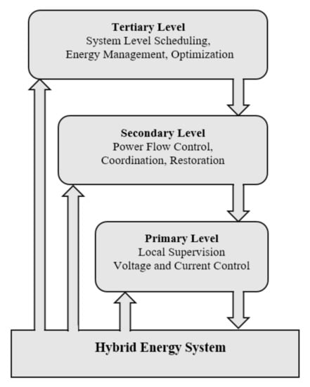
Figure 1.
Hierarchical control levels of a hybrid energy system.
2.1. The HES Structure
The structure of the proposed HES is presented in Figure 2. It consists of a photovoltaic (PV) array, energy storage unit (ESU), and diesel generator (Gen). These components are connected to the utility grid at the distribution feeder. The grid is assumed to be incapable of satisfying the load demand throughout the day; thus, during the absence of grid power, the PV, ESU, and Gen support is expected. Structural-wise, the PV array is connected to a DC bus by means of a unidirectional DC–DC converter with the maximum power point tracking (MPPT) control. The ESU is constructed using Li-ion battery banks and is connected to the DC bus via a bi-directional DC–DC converter. Thus, the energy flow for the ESU is in both directions. The utility grid, community load, and generator are directly connected to the AC bus. The AC and DC sources are interfaced through one bidirectional inverter. This topology reduces the cost of integration of HES’s components [20]. To maintain the power balance of HES, a central controller with an embedded EMS is used. Due to the centralized control, the controller requires global information to fulfill the energy management needs; thus, the communication infrastructure needs to be established [21].
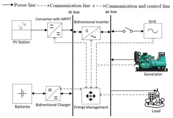
Figure 2.
Architecture of the proposed HES.
If is the hourly load demand of the system, in order to maintain the power balance of the system = ,
Here, is the hourly net output power of HES. The are the hourly power supplied by grid, PV, ESU, and diesel generators, respectively, according to the devised EMS.
2.2. The Stateflow (SF)
The SF is an add-on program for MATLAB and is explicitly linked to Simulink [22]. It is best used to mimic and simulate event-driven systems. SF is well suited for a reactive system, where multiple subsystems respond to the events happening in their surroundings while remaining aware of each other operations. It provides a graphical editor on which the objects are dragged from the design palette to create an extended finite state machine (FSM) function. Further, SF simplifies the system modeling and accommodates more complex logic by adding hierarchy, parallelism, events, actions, history, and truth tables, etc. These important extensions and flexible syntax increase the usefulness of SF to model the behavior of a complex system. Moreover, the excellent GUI guarantees strong evidence about the consistency, correctness, and completeness of system behavior [23]. To illustrate the concepts of SF, a simple example of a common compact disc (CD) player is shown in Figure 3.
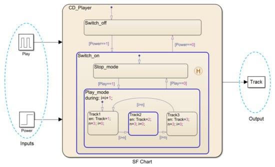
Figure 3.
Illustration of common compact disk player’s operation using SF.
The root for execution of the SF model is called the SF chart. It holds a mixture of data, state, and transition diagrams that characterize an operation. The chart interacts with MATLAB/Simulink through input and output ports. The basic object in a chart is called a state. The state can be active (on) or inactive (off); an active state implies a state activity due to event execution or fulfillment of certain conditions. For the CD player example, the Switch_on is active when the condition for transition (CFT), i.e., Power = 1, is met. During execution, an active state is denoted by a blue-lined rectangular. Moreover, several states can be activated simultaneously, which means multiple events can take place at one time. This is illustrated by Switch_on, Play_mode, and Track2, which are all running in parallel. Since SF is organized hierarchically, each state is allowed to have a number of sub-states. The top level of the hierarchy is called a super-state, while the inner states are termed as parent- or child-state. The execution order of a parent–child state is based on two rules: (1) the child state is executed only after the parent is activated, and (2) the parent completes its execution only after all its child states have been evaluated. All states can have two types of decomposition, i.e., exclusive (OR) or parallel (AND). The OR decomposition means that only one child state can be active at a time. In contrast, for AND, all child states are active at the same time. The states with AND and OR compositions are indicated by dashed and solid borders, respectively.
In the given example, CD_Player is the super-state. It has two child states, namely Switch_on and Switch_off. Further, Switch_on is the parent of two child states, i.e., Stop_mode and Play_mode. Going down the hierarchy, Play_mode has three child states: Track1, Track2, and Track3. They are in a mutually OR relationship. The symbol H is the history function; it maintains the previous setting/record of Switch_on state in case of sudden interruption. The input/output data are variables that record the values used by the chart. In the given example, Power and Play are the input data read from Simulink through its input ports. Similarly, Track is the output of the SF execution and is passed to Simulink once the operations are completed. The state labels denote the state identifier. It has three optional types of actions. First, the entry actions are executed upon entering the state. In our example, the state Track1, for instance, has an entry action that consists of assigning the value 1 to the variable Track. Second, “during” actions take place when the state is active and there is no valid outgoing transition. The “during” action can be seen in the state Play_mode, where the counter is used to increment the value of variable i. Third, the exit actions are performed when the state is exited. The transition represents a passage between two nodes that can be states or junctions. The transition label characterizes the circumstances under which the system moves from the source to the destination. The label has a format such as E[CFT] {CA}/{TA}, where E is an event that causes the transition to take place provided the CFT in the form of a Boolean expression is valid. The CA and TA are the conditions action and transition action, respectively, which can be the assignment or event broadcast. The CA is executed when CFT evaluates to true, while the TA is executed when the destination state is determined to be valid and the CFT is true. However, all these elements are optional.
2.3. Implementing EMS Using STATEFLOW
The EMS controls the energy flow among different sources, i.e., PV, ESU, and Gen, with the load. Its objective is to maintain the power balance while satisfying load demand under the operational constraints of the system. In this particular study, the EMS is designed to accomplish two main tasks: (1) to ensure uninterrupted supply of electricity in the presence of load shedding, and (2) to optimize the utilization of available energy generated from both renewable and conventional sources. The HES can be modeled in SF where the states represent different modes of operation for HES. The HES switches between these states according to the predefined operating conditions of the EMS. Figure 4 shows the SF chart for the HES operation.
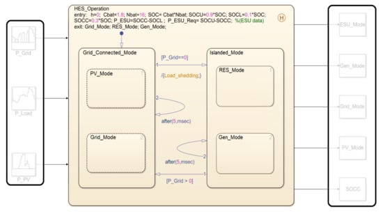
Figure 4.
The HES operation in SF.
The variables P_Grid, P_PV, and P_Load are inputs to the chart, while the ESU power (P_ESU) is defined as local data in the super-state HES_Operation. It is based on SOC and defined as the maximum power that ESU can constantly deliver for 1 h. Similarly, P_Gen is defined in the Gen_Mode state as constant data. The term “h” represents the time-step and is expressed in hours. At the output, Grid_Mode, PV_Mode, ESU_Mode, and Gen_Mode track the energy transactions (for each time-step) among various parts of the system. The variable SOCC represents the current SOC; it maintains the record of SOC for each hour.
The state diagram is hierarchical with both AND and OR compositions. The names of the states suggest the operation of different units. The HES_Operation, which represents the overall operation of HES, has OR composition with two child states: Grid_Connected_Mode and Islanded_Mode. The former is the normal (default) operation, where the electrical grid is expected to fulfill the entire load demand. On the other hand, the Islanded_Mode specifies the operation using the alternative sources (PV, ESU, and Gen). This state is executed when load shedding occurs. Further, Grid_Connected_Mode has AND composition of two child-states, i.e., PV_Mode and the Grid_Mode, whereas the Islanded_Mode contains two child states, RES_Mode and Gen_Mode, with OR composition.
The chart utilizes two types of transitions: inter-state and the intra-state. The inter-state transition is prioritized; it changes the operation from Grid_Connected_Mode to Islanded_Mode and vice versa (according to CFT). On the other hand, the intra-state transition is evaluated if the inter-state transition is not executed. It has a temporal logic operator (timer) to represent the for-loop construct. Table 1 describes the events and the CFT for the HES_Operation state. Based on the hourly values of the available data, the operating scenario is created for each time-step (hour) of the chart execution. Under different operating scenarios, different operational modes of HES are activated. The operating modes implemented using states can be seen in Figure 4.

Table 1.
The parent–child relationship and the condition for transition (CFT) for HES_Operation.
3. Modeling of HES Components
This section describes the mathematical modeling of different components of HES. However, the major difference between this work and previously documented works [7,24,25] is that the proposed HES incorporates the behavior of load shedding.
3.1. PV Cells
The output power of a PV is calculated using the single diode model [26]. The PV output current depends on the input data in form of the irradiance (in W/m2) and temperature (in °C). Figure 5 presents the single diode model of PV according to [27] while the output current of PV is given by
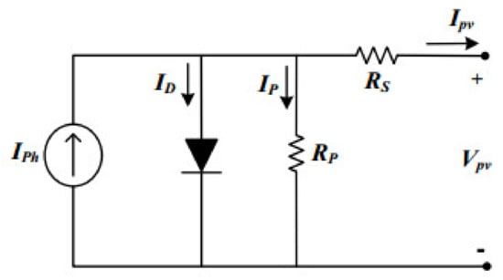
Figure 5.
PV single diode circuit model.
Here, ISC-STC represents short circuit current at standard test conditions (STC), ki is the short circuit current coefficient given by the manufacturer, T is the temperature of the module in Kelvin, TSTC represents the temperature at STC and is considered 298 °K, whereas G refers to cell surface irradiance, GSTC is the irradiance at STC, which is equal to 1000 W/m2, VT = akT/q denotes thermal voltage, a is the ideality factor and ranges between (1≤ a ≤ 2) [28], whereas q is the electron charge and is considered 1.602 10 −19 C, and K represents the Boltzmann constant taken as 1.381 × 10⁻²³ J/K. The RS and RP represent series and shunt resistances, respectively [29].
Due to the transcendental nature of (2), the Newton–Raphson method is applied to solve the equation iteratively by considering the output voltage (VPV) from 0 to VOC_STC. Furthermore, the peak of the P–V curve is continuously tracked using the perturb and observe (P&O) MPPT method [30]. The implementation of the P&O method using the SF is given in Figure 6. The PV output power for a given G and T is calculated as = (Vmpp × IPV). Thus, the instantaneous output power of PV with N number of modules in the array can be written as [31]
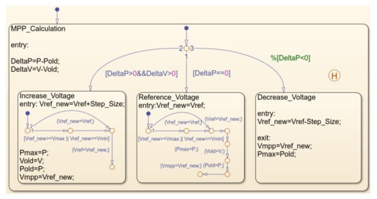
Figure 6.
Stateflow chart implementation of the P&O algorithm.
The actual values of G and T are taken from data set for the Quetta region, which is provided by [32]. Other PV parameters are taken from [33].
3.2. The ESU
The charging and discharging process is controlled by estimating the SOC of batteries. The model presented in [34] is used to calculate the SOC of ESU, i.e.,
where refers to battery efficiency and is assumed 100% for both the charging and discharging process. denotes the voltage of a DC bus (480 V), and is the time step set equal to 1 h. The represents the charging and discharging power of battery according to its required (charging) and available (discharging) power, respectively. The power required by ESU (P_ESU_Req) is the minimum amount of power that, if applied continuously, increases the state of charge of ESU from the initial to the upper limit (i.e., SOCU) in the time-step ∆t. The P_ESU_Req is given as
Likewise, the power available with ESU (P_ESU) is the maximum amount of power that ESU can deliver continuously before reaching the lower limit (i.e., SOCL) in one time-step. The P_ESU is given as
Here, is the nominal battery capacity for a single unit in kWh. Whereas, represents the total number of batteries in the ESU. To ensure batteries durability, their SOC should be confined within SOCU and SOCL. The SOCU and SOCL are set as 90% and 10%, respectively [35]. It means that the energy is stored in the ESU up to 90% of total rated capacity (SOCU) to avoid overcharging. Similarly, ESU stops discharging when the SOC level reaches 10% of its rated capacity (SOCL) to avoid over-discharging.
3.3. Generator
A split (two-tier) diesel generator system, as shown in Figure 7, is proposed; this is against the commonly used single generator [36,37]. The reason is to allow the commitment of generators to match the load demand at a specific instant, thus minimizing the fuel consumption and net CO2 emission. Furthermore, this structure increases the reliability and the redundancy of the system. The first generator, Gen1, is smaller in size (10 kW) as compared to the second generator, Gen2 (20 kW). Gen1 will be turned on when the required load demand is low. Accordingly, Gen2 will be started when the demand exceeds the capacity of Gen1. In the case of peak demand, both generators will operate simultaneously. For this research, the selection of an appropriate generator is performed by calling the truth table function in the SF. It should be noted that the generators are only turned on when there is a need to cover the energy deficit during load shedding intervals. This condition applies when the PV and ESU are not able to meet the load demand. In general, the power output of a generator can be expressed according to the rated power () and its efficiency ().
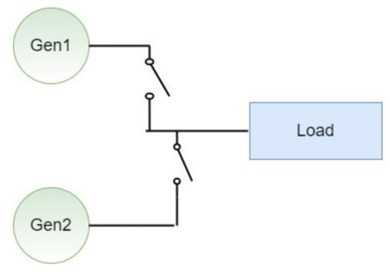
Figure 7.
Split generator system.
Accordingly, the fuel consumption of the generator can be calculated using the following formula.
Here, refer to the coefficients of the fuel consumption curve. Their values are 0.246 and 0.08145, respectively [38]. While represent the rated power and the generated power of the generator (in kW), respectively. Since this research considers two generators, the total power supplied by the generator system at time (t) is the sum of the individual generator contribution. It can be expressed as
P_Gen1 and P_Gen2 represent the power supplied by the Gen1 and Gen2, respectively. The values for power (P_Gen1, P_Gen2) and fuel consumption (FuelGen1, FuelGen2) of corresponding generators can be found through Equations (7) and (8), while is a binary variable that describes the state of the considered generator at a specific hour. In case the Gen1 is working and Gen2 is not working at any hour, the corresponding values will be and , respectively. This research considers suitable diesel generators from [39] to supply standby power in the proposed HES. Some technical parameters of the main components of HES are presented in Table 2.

Table 2.
Technical specifications of the HES components.
3.4. Case Study
The specific case study concerns on the reliability and availability of electricity supply in an area within Quetta City, a region in Baluchistan, Pakistan (30.1798° N, 66.9750° E). The problem is unique because it incorporates the real-time load-shedding scenario that requires intervention from the HES. The load shedding is a condition whereby the electricity supply to a specific area is cut off to allow other areas to fulfill their electric power demand. This is normally scheduled on an hourly basis by the national electric power regulatory authority. The load shedding is necessary due to the acute inadequacy of power generation. In the case of Quetta, the shedding is not expected to reduce in the near future as the electricity demand is growing, while the supply is not coping at the same rate. Despite these difficulties, this region has the tremendous potential of indigenous renewables, particularly solar. Characteristics of high solar irradiance and moderate temperature of Quetta make it an ideal candidate for PV generation. Furthermore, with the high tariff imposed by the utility provider to the customer, a PV system is economically viable. Furthermore, PV installation also has much faster construction times (18 to 24 months); thus, the solution can be realized much earlier compared to building a large conventional power plant.
To represent the behavior of load shedding, the supply from the utility is plotted in the form of a unit step function [10]. Figure 8a shows the daily power supply schedule of a local distribution feeder of Quetta city for one summer day (14 June 2020) [40]. The off states (depicted on the x-axis) reflect shedding durations; on average, it is 5 h a day. However, the schedule can differ for the summer and winter seasons. The average load demand profile is required to estimate the amount of electricity being used by the community. In this case study, a local load profile of a small residential community (with limited public facilities) within Quetta city is considered [41]. Two load profiles are considered: one for the summer season (March to August) and the other for the winter season (September to February). The load curves showing the hourly load shape are given in Figure 8b. The daily energy consumption for the summer and winter is 345 and 309 kWh, respectively. The peak power usage is at 26.66 and 23.91 kW for both seasons. Further, the load curve is categorized into two time zones, according to the Pakistan time-of-usage (TOU) tariff. The peak period is from 18 to 22 h, while the remaining 20 h are the off-peak. In order to simplify the observation, it is assumed that the local and grid peak demands coincide with each other.
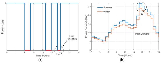
Figure 8.
(a) Hourly profile of power grid supply during summer (inclusive of load shedding durations). (b) The community load demand on an hourly basis.
Regardless of the problems, Quetta has the tremendous potential for indigenous renewables (particularly solar). Characteristics of high solar irradiance and moderate temperature make this region suitable for PV generation. Figure 9 demonstrates the annual climatological data (solar radiation, ambient temperature) of Quetta logged from August 2019 to August 2020, taken from Solcast (solar resource assessment and forecasting data) [32]. The data indicate the mean value of global horizontal irradiance (GHI) of 5503 kWh/m2/day.
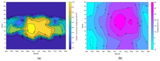
Figure 9.
(a) Heat map view of annual solar irradiance, and (b) annual ambient temperature of Quetta.
4. Execution of SF Chart and Operation Modes of HES
Initially, the SF chart (referred to Figure 4) is inactive; it is triggered after getting input signals from Simulink. The state HES_operation is entered by executing its entry actions. It defaults into Grid_Connected_Mode. Due to the AND composition, its child-states PV_Mode and Grid_Mode are executed simultaneously. In the same way, child states of PV_Mode (PV_to_ESU_Mode, PV_to_Load_Mode) and Grid_Mode (Grid_to_ESU_Mode) are executed according to the set priority. After evaluation, the state data of the Grid_Connected_Mode are updated. Then, the CFT is checked; if P_Grid=0 is valid, the inter-state transition is activated; otherwise, intra-state transition is evaluated. The intra-state transition (if performed) activates the Grid_Connected_Mode again and repeats the state activity in the next time-step. Without loss of generality, we focus on the first case, the inter-state transition. This transition results when the operation leaves Grid_Connected_Mode. Upon exiting, Grid_Connected_Mode (with all the child states) is marked inactive. During the inter-state transition, the event load_shedding is broadcasted, and therefore, the state Islanded_Mode becomes active. The execution in the Islanded_Mode is not independent. The solid borders in Figure 4 indicate the OR composition of the child states. Among the child states, either RES_Mode or Gen_Mode can be active at a time. Further, the states in the RES_Mode and Gen_Mode become active concurrently due to the AND formation. After executing all the child states, the Islanded_Mode is exited. The iteration continues for all the input data for each time-step. The chart transfers the output data to MATLAB and goes to the sleeping stage. The complete operation of HES controlled by EMS is shown in Figure 10.
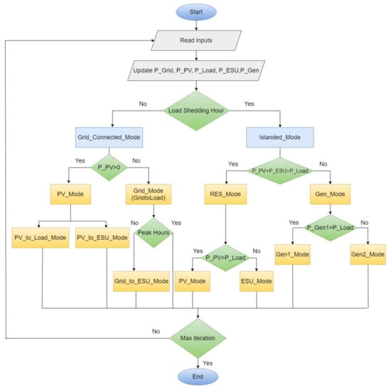
Figure 10.
EMS-based operation of HES.
4.1. The Grid_Connected_Mode
The Grid_Connected_Mode is invoked for the normal system operation, i.e., the utility grid is the main source of energy to fulfill the load demand. Moreover, the load shedding is not expected to occur during this period. The execution of the Grid_Connected_Mode ensures the electricity supply to the load is not interrupted and at the same time takes advantage of the availability of the PV energy for economic benefits and supporting the grid operation. The active state chart of Grid_Connected_Mode is shown in Figure 11a. It is assumed that in the absence of shedding, the grid has sufficient capacity to satisfy the load and charge the ESU. However, ESU charging through the grid takes place during the off-peak hours (excluding peak hours, i.e., 18–22 h). Meanwhile, it is possible for several events to take place during Grid_Connected_Mode. For example, if PV power is available, it is used to charge the ESU and contribute to the load. The utilization of available PV power takes place in the child states PV_to_ESU_Mode and PV_to_Load_Mode. Both are child states of PV_Mode. The decision on the transferred energy is based on the level of SOC of the ESU. If SOCC < SOCU, charging the ESU is the first priority. Once the SOCC reaches the SOCU, the remaining PV energy (PV_Surplus) is used to contribute to the grid power supply operation. The PV_to_ESU_Mode enables PV energy to be stored and consumed at a later stage when the PV is not available. In practice, this operation is realized using a DC–DC converter (with MPPT control) and a bi-directional DC charger. On the other hand, the PV_to_Load_Mode allows the surplus energy to support the grid operation, thus reducing the burden on the grid.
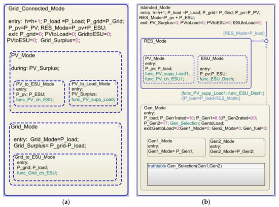
Figure 11.
(a) The state chart for Grid_Connected_Mode. (b) The state chart for Islanded_Mode.
4.2. The Islanded_Mode
The Islanded_Mode is triggered when load shedding occurs. At this time, no electric power is supplied from the grid. The SF chart of the Islanded_Mode during RES operation is shown in Figure 11b. During this period, the load demand is met either by the ESU and PV, or if necessary, using a diesel generator. The objective is to ensure the availability and continuity of supply and to optimize the utilization of the remaining energy from the PV (if available). The operations of RES and generator are represented by the child states RES_Mode and Gen_Mode, respectively. Since the PV is not always available and intermittent (weather dependent in nature), the generator is needed to sustain the load demand. However, the extraction of energy from PV is given priority due to the much higher operational cost of the latter.
To complement the energy excess/deficit, the ESU is charged or discharged. For example, if there is a surplus of PV power, the excess is used to charge the ESU. Accordingly, ESU delivers the deficit power to the load if the PV energy is not sufficient. These events take place in the child states, namely PV_Mode and ESU_Mode, respectively. In addition, the generator operation is performed using two generators of different sizes. The small generator Gen1 is activated first to supply the energy deficit between RES and load. However, Gen2 contributes if the load exceeds the power supply. The child states Gen1_Mode and Gen2_Mode represent the generator operation of HES. The parent–child relationships for Grid_Connected_Mode and Islanded_Mode, along with their respective CFT, are summarized in Table 3.

Table 3.
The parent–child relationship and the condition for transition (CFT) for Grid_Connected_Mode and Islanded_Mode.
5. Results and Discussions
The EMS for HES executed using a real data set of load shedding and a PV irradiance profile. The former is obtained from [40] and the latter from [32]. The simulations are performed for the load demand shown in Figure 8b, as well as the scheduled interruptions due to shedding. The main objective of the simulation is to test the resiliency of the HES when subjected to certain operating scenarios. In this context, resiliency is defined as the ability of the HES to provide an uninterrupted supply of electricity under different scenarios. The scenarios take into account the seasonal variations (summer and winter days), varying weather conditions (normal and abnormal days), and different load shedding patterns. The results are shown in Figures 13, 15, 17 and 19.
The results of each scenario are depicted in three plots. Plot a shows the charging and discharging operation of ESU. Plot b represents the transactions of energy performed under different operating modes (Grid_Mode, PV_Mode, ESU_Mode, Gen_Mode) of HES. Lastly, plot c shows the resiliency of HES in the varying load conditions.
5.1. Resiliency in Summer
The weather profile for a specific day (14 June 2020) during the peak summer season is shown in Figure 12. Since the surface solar irradiance is directly dependent upon the sky condition (clear, cloudy), the cloud opacity and the solar irradiance data are plotted to show the weather condition of the considered day. The constant availability of solar irradiance (of more than 1000 W/m2) during the daytime can be observed, indicating the normal weather conditions for the considered day.
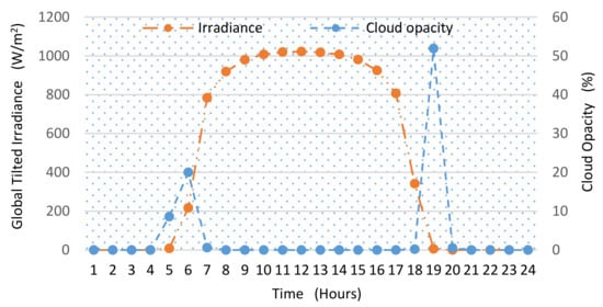
Figure 12.
The global tilted irradiance and the cloud opacity (on 14 June 2020).
The HES operation for this day is depicted in Figure 13. The load shedding is imposed for five hours during 6–8, 13–15, and 17–18 h. The charging/discharging profile of the ESU is shown in plot a. The ESU charges from the grid during the off-peak hours (Grid_ch_ESU) and during the excess of PV power (PV_ch_ESU). It discharges during the load shedding intervals (negative ESU_disch value indicates discharging). The limits (on power exchange) for batteries and the grid are maintained using [42]. Consequently, the SOC variations can be noted with the charging and discharging trend of the ESU. At any instant, the energy delivered by the ESU is given as
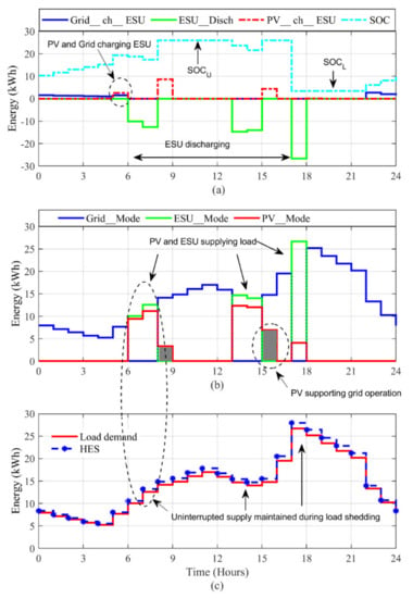
Figure 13.
Resiliency of the HES during peak summer season (on 14 June 2020). (a) ESU charging and discharging operation with SOC variations. (b) Grid, PV, and ESU modes. (c) The resiliency of HES vs. variable load.
Note that Equation (10) may result in < 0 due to the sporadic nature of PV. Such situation represents the PV surplus energy being absorbed by the ESU, i.e., within the bounds of Equations (5) and (6).
The flow of power under different modes is shown in plot b. It can be observed that the grid supply is maintained by PV (PV_Mode) and/or ESU (ESU_Mode) during the shedding hours. The standby generator is not utilized at all. Since the utilization of PV is given the first priority, the ESU is only used if P_PV is not sufficient to satisfy the load. The combined operation of PV and ESU can be seen during the hours 6–8, 13–15, and 17–18. Furthermore, during hours 8–9 and 15–16, PV supporting grid operation can also be observed (refer to grey color shaded curve in plot b). Finally, the integrated power supplied by HES against the varying load demand is shown in plot c. The results demonstrate the stable and uninterrupted power supply operation for a 24-h period despite the heavy load shedding experienced by the grid. This proves that the HES is sufficiently resilient under the control of the proposed EMS in providing uninterrupted supply even without the need to start the standby generator during the summer season having normal weather conditions.
For the case of abnormal weather (in the summer season), the irradiance and temperature profiles are based on the data obtained during a cloudy day (29 August 2019). The load is assumed to be the same as before, but a load shedding of 4 h is considered (based on the schedule allocated by the utility). The irradiance and cloud profile for the selected day is shown in Figure 14.
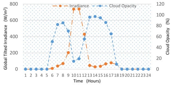
Figure 14.
The global tilted irradiance and the cloud opacity (on 29 August 2019).
The HES operation for this scenario is presented in Figure 15. Since the Islanded_Mode is found to be the most critical one, it is prudent to observe the system resiliency in this mode. As can be seen in Figure 14, due to the cloud covers, the irradiance is low, and the PV alone is not able to fulfill the load demand, even during daytime. The ESU contributes the major portion of load at 6–7 h. During another load-shedding interval, i.e., at hours 8–10, the combined contribution of PV and ESU is still inadequate to fulfill the load demand. Thus, the additional power from the generator (Gen1_Mode) is needed. Since the power deficit (less than 10 kW) is lesser than the capacity of the smaller generator, only Gen1 is utilized. Accordingly, due to the absence of PV power at hour 18–19 (late evening), the ESU and Gen1 maintain the power supply. Also due to the lower irradiance, PV is not able to support grid operation on this day. The contribution from different sources under different operating modes can be seen in plot b. Clearly, the system is resilient throughout the day, as indicated by plot c.
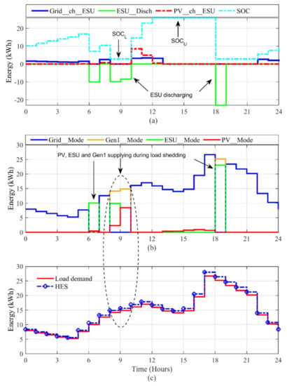
Figure 15.
Resiliency of HES during cloudy weather (summer day on 29 August 2019). (a) ESU charging and discharging operation with SOC variations (b) Grid, PV, ESU and Gen1 modes. (c) The resiliency of HES vs. variable load.
The results in Figure 13 and Figure 15 suggest that the proposed system is 100% resilient during both normal and abnormal days of the summer season. Despite the outage from the grid, the stable and uninterrupted power supply operation is achieved by the combined operation of all three alternate energy sources. The number of PV modules (Npv), ESU batteries (Nbat), and the power of a diesel generator (PGen) (for this simulation) are considered according to Table 4. Keeping in mind the economic feasibility, reliability, and the environmental effects, minimum sizes of HES components are selected to have peak power corresponding to the peak load power [43,44].

Table 4.
Considered values of HES components.
5.2. Resiliency in Winter
For the winter season, two scenarios are considered: moderate and extreme weather conditions. The weather profile that represents a moderate winter day (7 November 2019) is shown in Figure 16. As observed, the intensity of solar radiation for this day is lower than the summer season. Furthermore, the delayed sunrise and the early sunset significantly reduce the interval of the total received irradiance during this day.
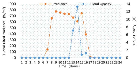
Figure 16.
The global tilted irradiance and the cloud opacity (on 7 November 2019).
The HES operation for this case study is shown in Figure 17. Here, the load demand for the winter season is used while the shedding follows the schedule set by the utility. The total load shedding for this day also consists of 4 h. Further, the same fleet size (NPV, NESU, and NGen) is used. As before, the goal is to observe the resiliency of HES when subjected to the operational constraints and variability of the weather. Due to the delayed sunrise, the PV production starts later (at hour six) in the morning, as shown in Figure 16. Thus, during the late evening and early morning, the alternative sources have to be utilized. As the PV is not producing sufficient power in the morning, the ESU discharges at 6–7 h and supports the power supply operation along with PV. At 7–8 h, the grid resumes the power supply. During this time, the ESU starts to charge from the PV and surplus grid (referred to plot a). During the hours 8–10, when the load shedding is enforced, the PV starts supplying. Since the load demand increases, the ESU contributes until the grid resumes the power supply. The ESU discharging operation (negative dashed line) can be observed in plot a, while the coordinated operation of PV and ESU can be seen in plot b. At hour 10 when the load shedding ends, the PV starts charging the ESU with the grid. Since both sources are charging ESU, the SOCU level is reached quickly. After the ESU is fully charged, the PV contributes to the load with the grid. The PV supplying load during grid_Connected_Mode can be observed from hours 11–16 in the grey color shaded area. This operation improves PV energy utilization. At hour 18–19 (late evening), the ESU discharges and maintains the power supply. This is because the PV is unavailable at this time. Please note that during this interval, the generator is not started as the ESU could solely satisfy the load requirement. At hour 19, the load shedding ends and the grid resumes the power supply. During this time, the SOC of ESU has reached the SOCL. Due to the peak time (hour 18–22), the grid is not able to charge the ESU. However, the charging process starts after hour two. The varying load and HES operation is shown in plot c. Clearly, the system resiliency can be observed throughout this day.
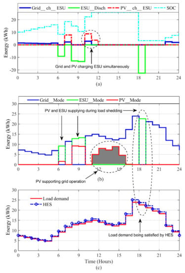
Figure 17.
Resiliency of HES during a moderate winter season (on 7 November 2019). (a) The ESU charging and discharging operation with SOC variations. (b) Grid, PV, ESU, and Gen modes. (c) The resiliency of HES vs. variable load.
Next, the HES performance during the extreme winter conditions is evaluated. The case study is presented for 2 January 2020. The temperature (at different time intervals of the day) falls below the freezing point and irradiance levels significantly decrease. The weather profile indicating the irradiance and cloud opacity is illustrated in Figure 18.
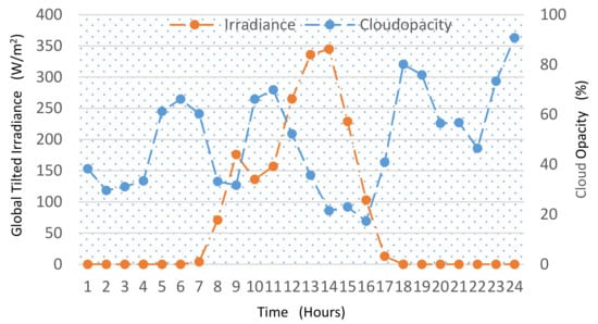
Figure 18.
The global tilted irradiance and the cloud opacity (on 2 January 2020).
The HES operation for this day is shown in Figure 19. The load shedding for this day happens for 7 h. At night, shedding happens for two consecutive hours, i.e., hours 2–4. Since the ESU can sustain the load for the first hour only, the remaining period of the shedding (3–4) has to be supported by Gen1. During hours 6–7, the demand is fulfillled again by Gen1 and ESU because the PV production has not started. When the load shedding reoccurs at hour 8–9, the PV and ESU start supplying at this interval. However, since the demand increases, the generator has to be utilized. The duration of the generator in operation is determined by the present SOC (SOCc), as shown in plot a. If SOCL is reached, Gen1 is turned on. At noon, i.e., hour 12–13, PV and ESU coordinate together to sustain the demand. At hours 16–18, load shedding is imposed again. ESU supplies during the first hour (16–17), but in the next hour (17–18) Gen2 (Gen2_Mode, pink) is needed because Gen1 cannot meet the load requirements during this period. Using this EMS strategy, the HES system has maintained the resiliency, as shown in plot c.
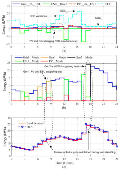
Figure 19.
Resiliency of HES during an extreme winter season (on 2 January 2020). (a) ESU charging and discharging operation with SOC variations. (b) Grid, PV, ESU, Gen modes. (c) The resiliency can be seen.
The successful outcomes of the proposed approach can be observed by the consistency of the power supply during all the considered scenarios. Despite the heavy load shedding from the grid, varying load demands are satisfied even during the abnormal weather conditions. In addition, the continuous exploitation of PV and surplus grid power indicates the optimized utilization of the available energy. Furthermore, the scheme also results in the lowest possible burden on the grid. This is because of PV support to grid operations during the daytime. For further assessment, simulations are performed for a one-year period logged from August 2019 to August 2020. The annual results are illustrated in Figure 20. In particular, both generator’s (Gen1 and Gen2) operation can be clearly seen in the zoomed plot. This shows the emergency conditions in terms of the cloudy sky scenario. The Gen_Mode is activated only when the demand exceeds the PV and ESU power during load shedding. Over the entire year (366 days, 8784 h), such situation occurs for 80 h at different time intervals. The Gen1 operates for 49 h, while the Gen2 is triggered for 31 h. It is evident that Gen1 (being smaller) is utilized more than Gen2 in order to minimize the fuel consumption. The results prove the optimized outcome of the proposed EMS. The annual contribution from different energy sources is described in Table 5. The annual net energy demand is 119,519 kWh. Accordingly, the seasonal contribution from these sources is plotted in Figure 21. Clearly, the contribution of HES is greater in the summer season due to the higher availability of PV power.
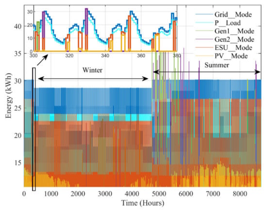
Figure 20.
The annual energy generation mix of HES and the load demand.

Table 5.
Annual contribution from different energy sources.
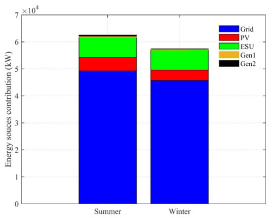
Figure 21.
Contribution of different energy sources in summer and winter seasons.
6. Conclusions
This work presented a Stateflow (SF)-based energy management strategy (EMS) for a renewable-based hybrid energy system (HES) that experiences regular load shedding. The EMS controls HES operation during both modes of operation, i.e., grid-connected mode and islanded mode. It optimizes the energy production and utilization in addition to achieving uninterrupted power supply during load shedding. The performance of the system is investigated using a real data set of irradiance, temperature, and load shedding schedule for a small residential community in the city of Quetta, Pakistan. The simulation results proved the resiliency of the HES in different weather and load shedding conditions. Furthermore, the superiority of the control strategy is confirmed in terms of reduced grid burden by prioritizing the utilization of PV energy. Additionally, the research has found that the application of SF minimizes the computational complexity of the problem solving and advantageously demonstrates the behavior of an event-driven system.
To improve the research, future work should focus on the following key areas. First is to develop a more refined control strategy for the HES pool (i.e., the interconnection of several HES) and to study its effectiveness in handling the load shedding issue. Second is to extend the SF utilization by considering the multi-layer control design for HES that will contain a prediction layer (to forecast demand, PV, and grid vulnerabilities), energy management layer (to improve energy efficiency), and operational layer (for current and voltage control). The third key area is to focus on the techno-economic performance of HES by studying the impact of various HES configurations and energy management strategies on the energy yield of the system.
Author Contributions
Conceptualization, Z.S.; Methodology, M.P.B. and Z.S.; Formal analysis, M.P.B. and Z.S.; Investigation, M.P.B. and Z.S.; Funding acquisition, Z.S., S.A.K., W.A., A.R.B. and N.K.; Resources, Z.S.; Software, M.P.B., N.K. and S.A.K.; Supervision, Z.S. and A.R.B.; Validation, Z.S. and W.A.; Visualization, W.A. and S.A.K.; Writing—Review & editing, M.P.B., Z.S. and A.R.B. All authors have read and agreed to the published version of the manuscript.
Funding
This research was funded by the Higher Education Commission, Pakistan, under the HRDi-UESTP Scholarship Program and Ministry of Higher Education, Malaysia, under the Malaysia Rising Star Award grant. The grant was managed by Universiti Teknologi Malaysia under Vot. No.R.J130000.7823.4F919.
Data Availability Statement
The data that support the findings of this study were derived from the openly available data in a public repository at https://solcast.com/, (accessed on 14 May 2021) and http://ccms.pitc.com.pk/FeederDetails (accessed on 14 May 2021) by providing required information.
Acknowledgments
This article has been made possible by the support of the Centre of Electrical Energy Systems (CEES), School of Electrical Engineering, Universiti Teknologi Malaysia (UTM). The authors would like to thank Ministry of Higher Education, Malaysia and Higher Education Commission, Pakistan for providing resources and the financial support.
Conflicts of Interest
The authors declare no conflict of interest.
Nomenclatures
| P_PV | PV output power (kW) |
| P_ESU | ESU output power (kW) |
| P_Gen | Diesel generator output power (kW) |
| P_Grid | Grid power (kW) |
| P_Load | Energy demand (kW) |
| SOCC | State of charge of ESU current hour (kWh) |
| SOCU | Upper limit of state of charge (kWh) |
| SOCL | Lower limit of state of charge (kWh) |
| P_HES | Output power of HES |
| On-off binary variable | |
| Nominal battery capacity (kWh) | |
| Generator rated power (kW) | |
| Time step (hour) | |
| PV maximum output power | |
| Battery efficiency (%) | |
| Voltage of DC bus | |
| P_ESU_Req | Power required by ESU to reach SOCU (kW) |
| Generator efficiency (%) | |
| Fuel consumption of generator (L) | |
| Coefficients of fuel consumption curve (L/kWh) | |
| h | Time step (hour) in SF |
| PVtoESU | PV energy being supplied to ESU (kWh) |
| PVtoLoad | PV energy being supplied to load (kWh) |
| GridtoESU | Grid energy being supplied to ESU (kWh) |
| GridtoLoad | Grid energy being supplied to Load (kWh) |
| PV_Surplus | PV surplus energy (kWh) |
| Grid_Surplus | Grid surplus energy (kWh) |
| ESU_Disch | Energy discharge from ESU (kWh) |
| PV_supp_Load | PV operation for supplying load (SF function) |
| Grid_ch_ESU | Grid operation to charge ESU (SF function) |
| PV_ch_ESU | PV operation to charge ESU (SF function) |
Abbreviations
| CFT | Condition for transition |
| HES | Hybrid energy system |
| PV | Photovoltaic |
| EMS | Energy management strategy |
| SF | Stateflow |
| ESU | Energy storage unit |
References
- Abushnaf, J.; Rassau, A. Impact of energy management system on the sizing of a grid-connected PV/Battery system. Electr. J. 2018, 31, 58–66. [Google Scholar] [CrossRef]
- Worighi, I.; Geury, T.; El Baghdadi, M.; Van Mierlo, J.; Hegazy, O.; Maach, A. Optimal design of hybrid PV-Battery system in residential buildings: End-user economics, and PV penetration. Appl. Sci. 2019, 9, 1022. [Google Scholar] [CrossRef]
- Shivaie, M.; Mokhayeri, M.; Kiani-Moghaddam, M.; Ashouri-Zadeh, A. A reliability-constrained cost-effective model for optimal sizing of an autonomous hybrid solar/wind/diesel/battery energy system by a modified discrete bat search algorithm. Sol. Energy 2019, 189, 344–356. [Google Scholar] [CrossRef]
- Mariam, L.; Basu, M.; Conlon, M.F. Microgrid: Architecture, policy and future trends. Renew. Sustain. Energy Rev. 2016, 64, 477–489. [Google Scholar] [CrossRef]
- Kumar, J.; Agarwal, A.; Agarwal, V. A review on overall control of DC microgrids. J. Energy Storage 2019, 21, 113–138. [Google Scholar] [CrossRef]
- Grami, M.; Rekik, M.; Krichen, L. Power dispatch strategy for interconnected microgrids based hybrid renewable energy system. Int. J. Renew. Energy Res. 2018, 8, 838–850. [Google Scholar]
- Khawaja, Y.; Allahham, A.; Giaouris, D.; Patsios, C.; Walker, S.; Qiqieh, I. An integrated framework for sizing and energy management of hybrid energy systems using finite automata. Appl. Energy 2019, 250, 257–272. [Google Scholar] [CrossRef]
- Ndwali, P.K.; Njiri, J.G.; Wanjiru, E.M. Optimal operation control of microgrid connected photovoltaic-diesel generator backup system under time of use tariff. J. Control. Autom. Electr. Syst. 2020, 31, 1001–1014. [Google Scholar] [CrossRef]
- Dali, M.; Belhadj, J.; Roboam, X. Hybrid solar-wind system with battery storage operating in grid-connected and standalone mode: Control and energy management—Experimental investigation. Energy 2010, 35, 2587–2595. [Google Scholar] [CrossRef]
- Siraj, K.; Awais, M.; Khan, H.A.; Zafar, A.; Hussain, A.; Zaffar, N.A.; Jaffery, S.H.I. Optimal power dispatch in solar-assisted uninterruptible power supply systems. Int. Trans. Electr. Energy Syst. 2020, 30, 1–15. [Google Scholar] [CrossRef]
- Bai, W.; Sechilariu, M.; Locment, F. DC microgrid system modeling and simulation based on a specific algorithm for grid-connected and Islanded modes with real-time demand-side management optimization. Appl. Sci. 2020, 10, 2544. [Google Scholar] [CrossRef]
- Rehman, S.U.; Qazi, M.U.; Shoaib, M.; Lashin, A. Feasibility study of hybrid energy system for off-grid rural electrification in southern Pakistan. Energy Explor. Exploit. 2016, 34, 468–482. [Google Scholar] [CrossRef]
- Hijjo, M.; Felgner, F.; Frey, G. Energy management scheme for buildings subject to planned grid outages. Int. J. Eng. Sci. Technol. 2016, 3, 58–65. [Google Scholar]
- Xiao, J.; Wang, P.; Setyawan, L. Multilevel energy management system for hybridization of energy storages in DC microgrids. IEEE Trans. Smart Grid 2016, 7, 847–856. [Google Scholar] [CrossRef]
- Vidal-Clos, J.-A.; Bullich-Massagué, E.; Aragüés-Peñalba, M.; Vinyals-Canal, G.; Chillón-Antón, C.; Prieto-Araujo, E.; Gomis-Bellmunt, O.; Galceran-Arellano, S. Optimal operation of isolated microgrids considering frequency constraints. Appl. Sci. 2019, 9, 223. [Google Scholar] [CrossRef]
- Heredero-Peris, D.; Chillón-Antón, C.; Pagès-Giménez, M.; Montesinos-Miracle, D.; Santamaría, M.; Rivas, D.; Aguado, M. An enhancing fault current limitation hybrid droop/V-f control for grid-tied four-wire inverters in AC microgrids. Appl. Sci. 2018, 8, 1725. [Google Scholar] [CrossRef]
- Feng, X.; Shekhar, A.; Yang, F.; Hebner, R.E.; Bauer, P. Comparison of hierarchical control and distributed control for microgrid. Electr. Power Compon. Syst. 2017, 45, 1043–1056. [Google Scholar] [CrossRef]
- Hooshmand, A.; Asghari, B.; Sharma, R.K. Experimental demonstration of a tiered power management system for economic operation of grid-tied microgrids. IEEE Trans. Sustain. Energy 2014, 5, 1319–1327. [Google Scholar] [CrossRef]
- Bukar, A.L.; Tan, C.W.; Yiew, L.K.; Ayop, R.; Tan, W.-S. A rule-based energy management scheme for long-term optimal capacity planning of grid-independent microgrid optimized by multi-objective grasshopper optimization algorithm. Energy Convers. Manag. 2020, 221, 113161. [Google Scholar] [CrossRef] [PubMed]
- Habib, M.; Ladjici, A.A. Frequency control in off-grid hybrid diesel/PV/Battery power system. In Proceedings of the 4th International Conference on Electrical Engineering, Boumerdes, Algeria, 13–15 December 2015. [Google Scholar]
- Lim, H.; Zhai, Z.J. Review on stochastic modeling methods for building stock energy prediction. Build. Simul. 2017, 10, 607–624. [Google Scholar] [CrossRef]
- The MathWorks. Stateflow. R2018b. 2018. Available online: https://in.mathworks.com/products/stateflow.html (accessed on 1 January 2019).
- Drave, I.; Hillemacher, S.; Greifenberg, T.; Kriebel, S.; Kusmenko, E.; Markthaler, M.; Orth, P.; Salman, K.S.; Richenhagen, J.; Rumpe, B.; et al. SMArDT modeling for automotive software testing. Softw. Pract. Exp. 2019, 49, 301–328. [Google Scholar] [CrossRef]
- Colas, F.; Lu, D.; Lazarov, V.; François, B.; Kanchev, H. Energy management and power planning of a microgrid with a PV-based active generator for Smart Grid Applications. IEEE Trans. Ind. Electron. 2011, 58, 4583–4592. [Google Scholar]
- Reihani, E.; Sepasi, S.; Roose, L.R.; Matsuura, M. Energy management at the distribution grid using a Battery Energy Storage System (BESS). Int. J. Electr. Power Energy Syst. 2016, 77, 337–344. [Google Scholar] [CrossRef]
- Zhang, Y.; Lundblad, A.; Campana, P.E.; Benavente, F.; Yan, J. Battery sizing and rule-based operation of grid-connected photovoltaic-battery system: A case study in Sweden. Energy Convers. Manag. 2016, 133, 249–263. [Google Scholar] [CrossRef]
- Chin, V.J.; Salam, Z.; Ishaque, K. Cell modelling and model parameters estimation techniques for photovoltaic simulator application: A review. Appl. Energy 2015, 154, 500–519. [Google Scholar] [CrossRef]
- Ishaque, K.; Salam, Z. An improved modeling method to determine the model parameters of photovoltaic (PV) modules using differential evolution (DE). Sol. Energy 2011, 85, 2349–2359. [Google Scholar] [CrossRef]
- Ishaque, K.; Salam, Z.; Taheri, H. Accurate MATLAB simulink PV system simulator based on a two-diode model. J. Power Electron. 2011, 11, 179–187. [Google Scholar] [CrossRef]
- Tajuddin, M.F.N.; Arif, M.S.; Ayob, S.M.; Salam, Z. Perturbative methods for maximum power point tracking (MPPT) of photovoltaic (PV) systems: A review. Int. J. Energy Res. 2015, 39, 1153–1178. [Google Scholar] [CrossRef]
- Bhatti, A.R.; Salam, Z. A rule-based energy management scheme for uninterrupted electric vehicles charging at constant price using photovoltaic-grid system. Renew. Energy 2018, 125, 384–400. [Google Scholar] [CrossRef]
- Engerer, N. Historical and Typical Meteorological Year. 2020. Available online: https://solcast.com/historical-and-tmy/ (accessed on 8 August 2020).
- Kyocera. KD325GX-LFB. Kyocera Solar. 2019. Available online: https://www.kyocerasolar.com/ (accessed on 1 June 2019).
- Bhatti, A.R.; Salam, Z.; Sultana, B.; Rasheed, N.; Awan, A.B.; Sultana, U.; Younas, M. Optimized sizing of photovoltaic grid-connected electric vehicle charging system using particle swarm optimization. Int. J. Energy Res. 2019, 43, 500–522. [Google Scholar] [CrossRef]
- Li, X.; Hui, D.; Lai, X. Battery energy storage station (BESS)-based smoothing control of photovoltaic (PV) and wind power generation fluctuations. IEEE Trans. Sustain. Energy 2013, 4, 464–473. [Google Scholar] [CrossRef]
- Bukar, A.L.; Tan, C.W.; Lau, K.Y. Optimal sizing of an autonomous photovoltaic/wind/battery/diesel generator microgrid using grasshopper optimization algorithm. Sol. Energy 2019, 188, 685–696. [Google Scholar] [CrossRef]
- Shezan, S.A. Optimization and assessment of an off-grid photovoltaic-diesel-battery hybrid sustainable energy system for remote residential applications. Environ. Prog. Sustain. Energy 2019, 38. [Google Scholar] [CrossRef]
- Lujano-Rojas, J.M.; Monteiro, C.; Dufo-López, R.; Bernal-Agustín, J.L. Optimum load management strategy for wind/diesel/battery hybrid power systems. Renew. Energy 2012, 44, 288–295. [Google Scholar] [CrossRef]
- MEGA Power. MP-P Series. 2019. Available online: https://www.megapowersolution.com/products/50_HZ_international/24.html (accessed on 1 January 2019).
- Ministry of Energy (Power Division). Power Information Technology Company. 2019. Available online: http://roshanpakistan.pk/ccms/lss.php (accessed on 1 January 2019).
- Bakht, M.P.; Salam, Z.; Bhatti, A.R. Investigation and modelling of load shedding and its mitigation using hybrid renewable energy system. In Proceedings of the 2018 IEEE International Conference on Power and Energy (PECon2018), Kuala Lumpur, Malaysia, 3–4 December 2018; pp. 35–40. [Google Scholar]
- Riffonneau, Y.; Bacha, S.; Barruel, F.; Ploix, S. Optimal power flow management for grid connected PV systems with batteries. IEEE Trans. Sustain. Energy 2011, 2, 309–320. [Google Scholar] [CrossRef]
- Ani, V.A. Design of a reliable hybrid (PV/diesel) power system with energy storage in batteries for remote residential home. J. Energy 2016, 2016, 1–16. [Google Scholar] [CrossRef]
- Riffonneau, Y.; Bacha, S.; Barruel, F.; Delaille, A. Energy flow management in grid connected PV systems with storage—A deterministic approach. Proc. IEEE Int. Conf. Ind. Technol. 2009, 1–6. [Google Scholar] [CrossRef]
Publisher’s Note: MDPI stays neutral with regard to jurisdictional claims in published maps and institutional affiliations. |
© 2021 by the authors. Licensee MDPI, Basel, Switzerland. This article is an open access article distributed under the terms and conditions of the Creative Commons Attribution (CC BY) license (https://creativecommons.org/licenses/by/4.0/).