Article

Analysis of Variance of Dissimilar Cu-Al Alloy Friction Stir Welded Joints with Different Offset Conditions

1
Mechanical Engineering Department, Indian Institute of Technology (Indian School of Mines), Dhanbad 826004, Jharkhand, India
2
Mechanical Engineering Department, Birla Institute of Technology, Mesra, Ranchi 835215, Jharkhand, India
3
Faculty of Electrical Engineering, Automatic Control and Informatics, Opole University of Technology, 45-758 Opole, Poland
*
Author to whom correspondence should be addressed.
Appl. Sci. 2021, 11(10), 4604; https://doi.org/10.3390/app11104604
Submission received: 15 April 2021 / Revised: 12 May 2021 / Accepted: 14 May 2021 / Published: 18 May 2021
(This article belongs to the Section Mechanical Engineering)

Abstract

:
In this investigation, dissimilar material AA6061-T6 and Cu B370 were joined by friction stir welding (FSW). This paper presents a feasibility study of FSW to join Al-alloy and Cu-alloy. The experiment was conducted using general full factorial design by varying the tool rotation speed, weld speed, and probe offset, and by keeping the plunge depth constant. In this research work, a statistical model was established to build a connection between the process variables and outcomes—yield strength (YS), ultimate tensile strength (UTS) and % elongation (% E). Statistical tools such as analysis of variance and scatter diagrams were employed to evaluate the suitability of the models. In addition, the impacts of the process variables on the tensile properties were investigated. From the experimental results, it can be concluded that (i) an excellent weld joint could be obtained by keeping the softer Al plate at the retreating side with a probe offset of 2.0 mm towards the softer material, and (ii) maximum tensile properties were obtained at a higher tool-rotation speed, weld speed, and with a probe offset of 2.0 mm. Further, the fractured tensile specimens were investigated using a scanning electron microscope (SEM). From the analyses, it was noted that, during the tensile test, the weld joint failed with a brittle–ductile mixed fracture mode.

1. Introduction

In a conventional welding process, the joining of dissimilar materials, such as different grades of aluminum (Al) and copper (Cu), is considered to be a major challenge. This is due to the variations in the mechanical, chemical, and thermal properties of Al and Cu. However, FSW is one of the most promising solid-state joining processes, which can join the same or different base materials [1]. During this welding process, the generated temperature is below the melting point of the base materials, which helps the base materials to attain an elastic phase and be fused to each other [2]. The formation of a joint without using additional filler materials, alloying elements, and arc, reduces the chances of welding defects that occur in fusion welding. Moreover, during the FSW process, the energy consumption is low and there are no hazards related to radiation and fumes. Thus, the FSW process is superior to all conventional fusion welding processes [3]. A schematic diagram of the FSW process is presented in Figure 1.
Al and Cu joints are widely used for various applications, such as for electric conductors and the tubes of heat exchangers, a transformer’s foil conductor, and so on, due to their extensive properties, such as their high thermal and electrical conductivity, excellent corrosion resistance, and mechanical properties [5]. Therefore, many researchers have investigated the feasibility of using FSW to join Al-alloy and Cu-alloy. These researchers analyzed the dissimilar weld joints of aluminum and cooper and achieved flawless joints and they also observed defect free joints at low weld speeds and with high rotational speeds [6,7,8,9,10]. Experimental design tools play a key role in the engineering world for improving the manufacturing processes and decreasing variability. The design of experiments (DoE) is an efficient procedure for planning and designing experiments and for analyzing obtained experimental results. Based on the results, a statistical model for the experimental work can be established. This model helps in building a connection between the process variables and outcomes [11]. In some of studies, researchers used several DoE techniques, such as the Taguchi methodology, RSM, factorial design, ‘R’ programming, etc., to conduct experiments. Researchers have used the Taguchi method and ANOVA for their analyses and they developed mathematical models from the statistical analyses and noted that the weld speed had a more significant effect compared to other process parameters. From ANOVA analysis, they found that the probe offset had a notable effect on YS and UTS [12,13,14,15].
Apart from process variables such as tool rotation speed and weld speed, the position of the welded base plates (advancing side (AS) and retreating side (RS)) and probe offset (tool offset) also play important roles in achieving a sound defect-free joint and weld surface for the friction stir welding of joints of dissimilar materials [16]. Researchers found satisfactory results by maintaining Cu on the AS and soft materials on the RS [7,17]. Many researchers have investigated the effect of tool offset on the weld quality of the FSW of dissimilar materials. They performed FSW on Al alloy and Cu with varying tool offset of 0–2 mm and found the limiting value of the tool offset to be 1.2 mm on Cu side, beyond which irregular joints were observed [16,18]. In addition, the tilt angle of a tool plays a significant role in the friction stir welding of dissimilar materials. Many researchers have studied the effect of the tilt angle of a tool on the weld quality of the FSW of various dissimilar materials. They observed that a proper tool tilt angle helps in achieving (i) a defect-free joint and proper fusion of the base material, (ii) a better material flow during the FSW process, and (iii) good plastic deformation at the weld zone. However, a lower tool tilt angle will reduce the flow of materials and a higher tool tilt angle will produce flashes; thus, an optimal tool tilt angle is required for a smooth weld surface [19,20].
Various welding parameters have a remarkable impact on YS, UTS, and % E. Researchers have analyzed the mechanical behaviors of dissimilar FSW joints of Al and Cu. They concluded that the tensile properties of welded joints increase up to a maximum value with an increase in weld speed, but that further increase in weld speed beyond the optimal value decreases the tensile properties. Tensile properties were also investigated at various pin offsets and rotational speeds. They concluded that the UTS increases with tool rotational speed and with the decrease in the probe offset [16,18,21]. Some researchers have investigated tensile-tested specimens to understand the failure behavior of fractured surfaces. Fractured surfaces have been studied using SEM by some researchers; they observed cavities and large dimples on the fractured surface. Under SEM they found cleavage fractures and layered fracture surfaces and they also reported that the failure mode was brittle in nature. Some researchers used FESEM for a more detailed study of fracture surfaces and they found microscopic voids and dimples on fractured surface. They also concluded that the fracture mode was not purely ductile [7,17,22,23,24].
Many researchers have worked on dissimilar FSW joints of aluminum and steel. They successfully joined aluminum to steel using the FSW process. Sorger et al. developed an innovative overlap joint concept for single pass and multi pass configurations of the joining of Al with steel using the FSW process. They concluded that with a two-pass weld, the mechanical properties of the joints were improved. Researchers have also investigated important properties, e.g., high cycle fatigue in FSW joints. Lukacs et al. investigated the fatigue properties of dissimilar FSW joints of aluminum alloys and found a good correspondence in fatigue properties in a comparative analysis of base materials and welded joints [25,26].
In this experimental work, FSW of dissimilar materials, Al and Cu alloys, was successfully carried out. A superior weld joint was obtained by maintaining the harder Cu base plate at the advancing side and a probe offset of 2.0 mm towards the softer Al base plate was used. The objectives of this research work are: (i) to conduct experiments on the FSW of Al-alloy and Cu-alloy using a full factorial design of the experiment; (ii) to establish a statistical model that will help in understanding the connections between the process variables and outcomes; (iii) to investigate the impact of process variables on tensile properties; and (iv) to analyze the fracture surface of the tensile specimens.

2. Experimental Procedure

2.1. Materials

Aluminum alloy (AA) 6061-T6 and Cu B370 have high strength, very good electrical and thermal conductivities, excellent corrosion resistance, and mechanical properties. Therefore, in this study, these dissimilar alloys were used as the base material. The chemical compositions of AA 6061-T6 and Cu B370 are shown in Table 1a,b. The mechanical properties of AA 6061-T6 and Cu B370 are shown in Table 2.
The tool used in this experiment was a steel H13 tool (Figure 2) and the tool geometry is shown in Figure 3 and Table 3.

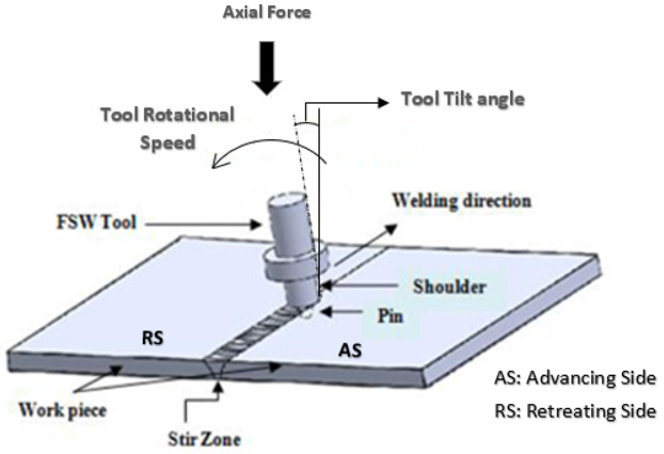
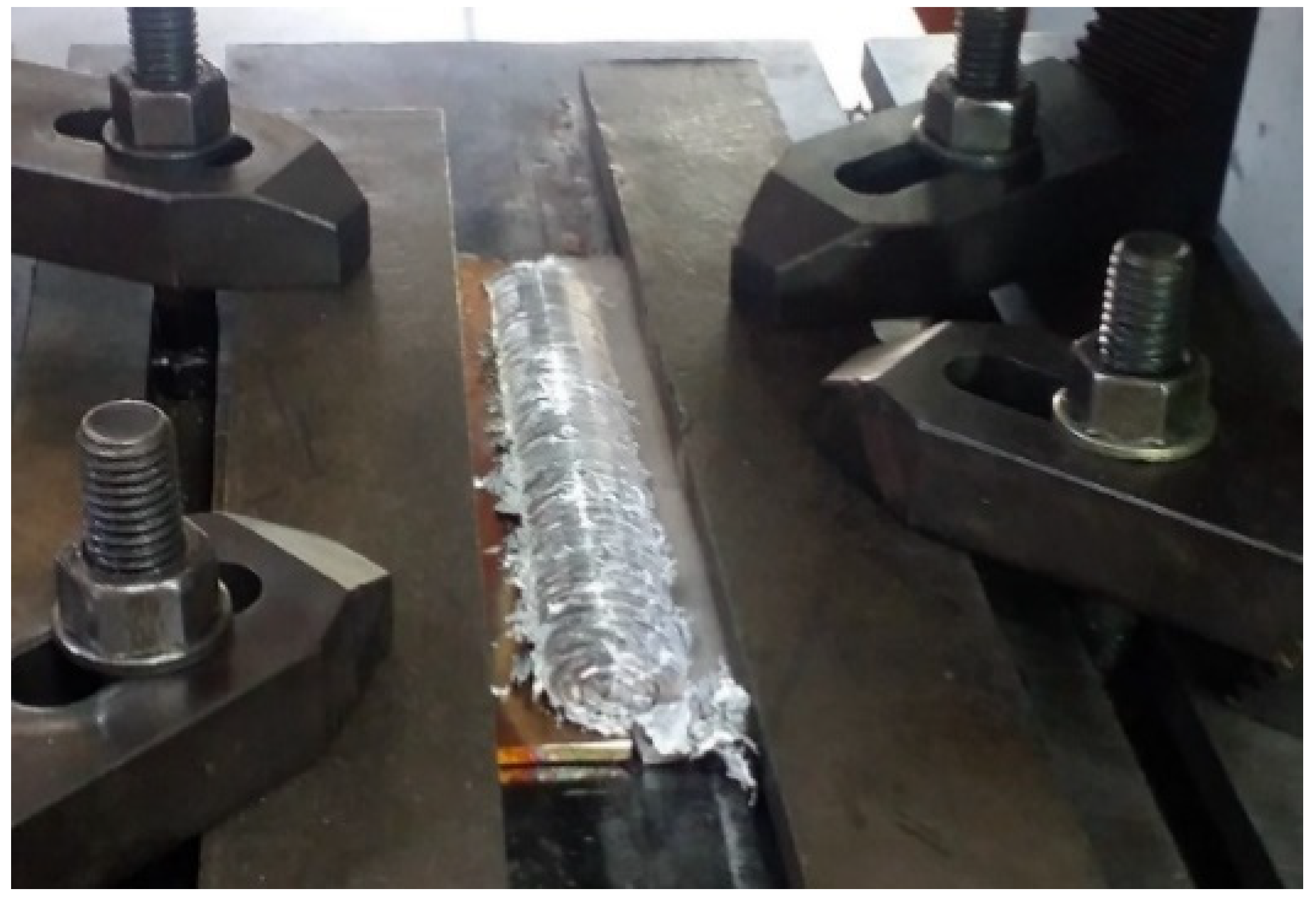
2.2. Experimental Set-Up

An instrumented linear numerically controlled FSW machine (ETA, WS004) was used to conduct the experiments (Figure 4). The two plates (dimensions 150 mm × 50 mm × 3 mm) were placed on the machine bed by keeping the edges required for a butt joint. The plates were fixed and clamped with a special fixture to avoid any displacement during the welding. To analyze the impact of the location of the base material on the quality of the FSW joint, the harder material, Cu, was fixed on both the AS and RS. A non-consumable tool was inserted into the tool holder of the linear numerically controlled FSW machine head. Table 4 shows the various welding variables used in the experiments. A constant tool tilt angle of 2° and a plunging depth of 0.1 mm was maintained in all the experiments. Figure 5 shows the pictorial view of the FSW joint after the welding process.
During the experiments, when the probe offset was kept at 1 mm and 1.5 mm using a combination of different tool RPMs and weld speeds (as mentioned in Table 4), the weld quality was found to be poor with an improper fusion and cracks on weld surface. However, the weld quality improved and showed proper fusion at a probe offset of 2 mm. The analysis of the impact of the probe offset on weld quality is noted in Section 4.3.

2.3. Experimental Design

In this study, the design of the experiments was chosen for a probe offset of 2 mm towards the softer material, Al, by maintaining different tool rotational speeds and weld speeds (as mentioned in Table 4). A 32 full factorial design, with the help of the software tool MINITAB 17, was used to select the experimental parameters for this study. During the experiments, two factors (tool rotation speed and weld speed) and three levels were chosen. Table 5 shows the combination of different welding variables used to carry out the experiments.

2.4. Tensile Testing Machine and Specimens

A universal testing machine (Model-HOUNSFIELD, H50KS) was utilized to determine the tensile properties of the FSW joint of AA 6061-T6 and Cu B370. Tensile test pieces were cut from the welded plate and the specimens were prepared as per ASTM E8M-04 guidelines (Figure 6).

3. Experimental Results

3.1. Experimental Data of Tensile Properties

Table 6 shows the tensile properties obtained by varying the welding parameters.

3.2. Development of the Statistical Model

MINITAB 17 software was used to analyze the outcomes of the experiments. Statistical models were formulated to establish the connection between the process variables and their outcomes in terms of YS, UTS and % E using regression analysis. The formulated regression models are shown as follows:
(a)
Yield strength (YS):
YS = 72.0 + 0.0126 × Rotation Speed + 0.114 × Weld Speed
(b)
Ultimate tensile strength (UTS):
UTS = 95.6 + 0.00808 × Rotation Speed + 0.0695 × Weld Speed
(c)
% Elongation (% E):
% E = 0.819 + 0.00462 × Rotation Speed + 0.0515 × Weld Speed

4. Analyses

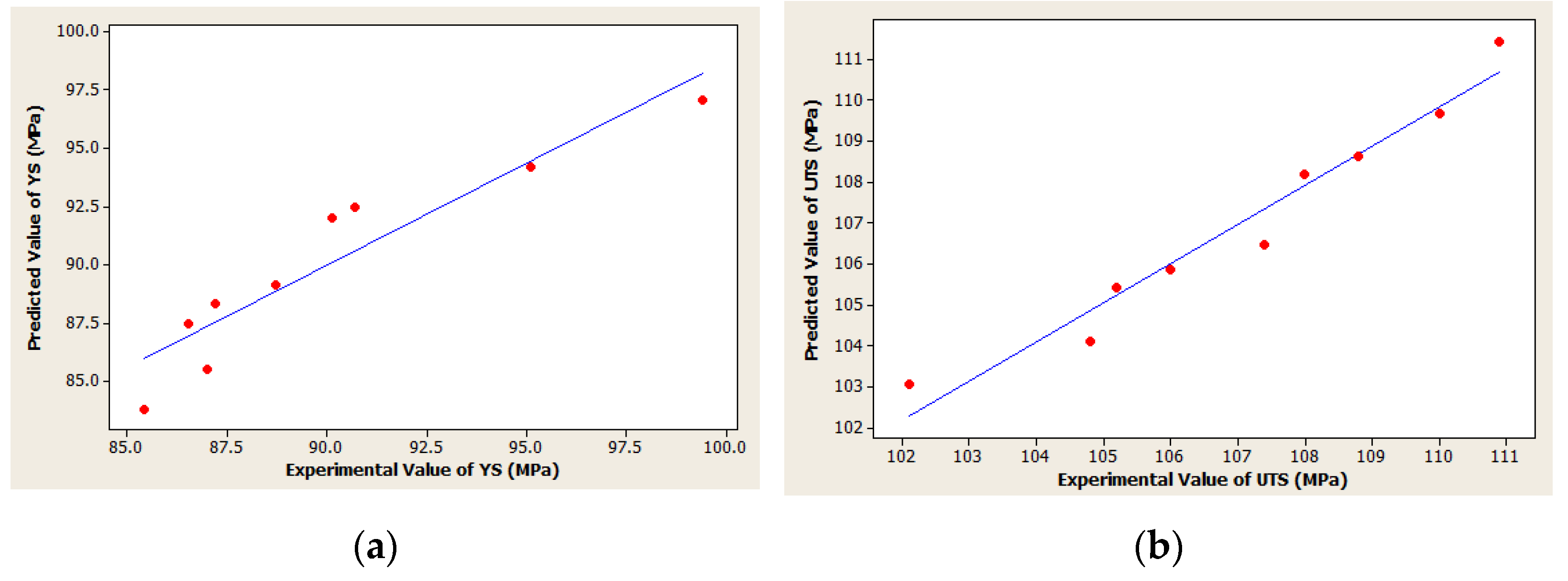
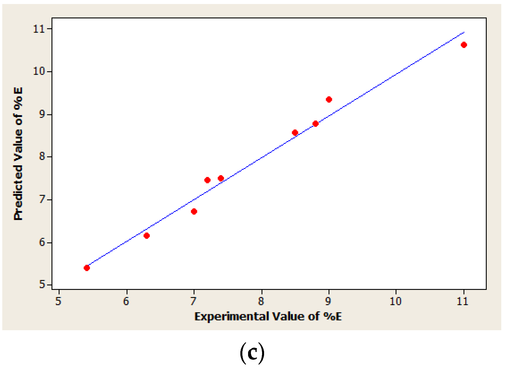
4.1. Testing Accuracy of Statistical Model

An F-test of ANOVA was used to evaluate the accuracy of the models formulated from the outcomes and the results are presented in Table 7. From the analyses, it was revealed that, at a 95% confidence level, Fcalculated > Ftabulated. Thus, these values reflected the best fit for the regression model, i.e., the adopted statistical models seemed to be accurate [27]. Table 8 shows the impact of the process variables on the outcomes (YS, UTS and % E). From Table 8II,III, it is found that the p-value ≤ 0.05, which means that the two welding variables have an outstanding impact on the outcomes of the experimental results (UTS, % E) [28].
Scatter diagrams further confirms the reliability of the regression model. The connection between the forecasted values derived from the models and the actual values of the FSW joint are reflected in the scatter diagrams. From Figure 7a–c, it can be seen that the actual values and the hypothetical values of the outcomes are widely dispersed and aligned along the 45° line. This orientation of the data reflects the adequacy of the formulated regression models [29].

4.2. Analysis on Effect of Position of Fixed Base Plate

In the case of FSW of dissimilar materials, most researchers have suggested that harder material should be kept at the AS to achieve an excellent weld joint surface. From the experimental analyses, it could be observed that an excellent weld quality was obtained when the Cu base was fixed at the AS (Figure 8). On the other hand, a longitudinal crack was observed in the weld surface when the Cu base was fixed at the RS (Figure 9). During welding, due to the frictional heat, a solid material at the RS is transformed into a semi-solid one and moves towards AS where it cools and is fused with the other material. Thus, when the Cu base plate (high melting point) was fixed at the retreating side, the frictional heat generated by the tool was insufficient to make the Cu soft enough to fuse with the Al base plate placed on the AS. As a result, a longitudinal crack developed due to improper fusion of the two materials [16].

4.3. Analysis on Effect of Probe Offset

As mentioned above, most studies have proved that, for the FSW of dissimilar materials, if welding is performed without the tool offset or at lower tool offset, then it is not possible to obtain a high-quality weld joint. Therefore, in the current experiment, various probe offsets were considered to analyze their impacts on the weld joint surface.
From Figure 10b,c, it can be seen that, when the tool probe is fixed at 1 mm and 1.5 mm, the weld joint and the surface quality were poor. However, when the tool probe was fixed at 2 mm for the softer material, Al (Figure 10a), a superior sound weld joint was obtained. From the experiments, it could be observed that, with an increase in the probe offset, the surface of the weld was smoother. This was due to the fact that when the tool probe advanced more towards the aluminum, a higher portion of the relatively softer Al is entered the stir zone, and this helped the smooth movement of the mixed materials due to there being less resistance from Al which produced a better weld surface [17].

4.4. Analysis on Impacts of Welding Variables on Outcomes (YS, UTS and % E)

4.4.1. Impact of Probe Offset on Tensile Properties

Figure 11 presents the tensile strengths of weld joints at different rotation speeds (710 RPM, 1000 RPM, 1400 RPM) and tool (probe) offsets (1 mm, 1.5 mm, 2 mm) at a constant weld speed (65 mm/min). It can be observed that, when the tool offset was kept at 2.0 mm towards the Al, the maximum tensile strength was obtained. However, with a decrease in the tool offset, the tensile strength decreased gradually. This was due to improper amalgamation of the materials in the stir zone (discussed in Section 4.3). As a result, the tensile strength of the weld joint was reduced due to improper fusion.

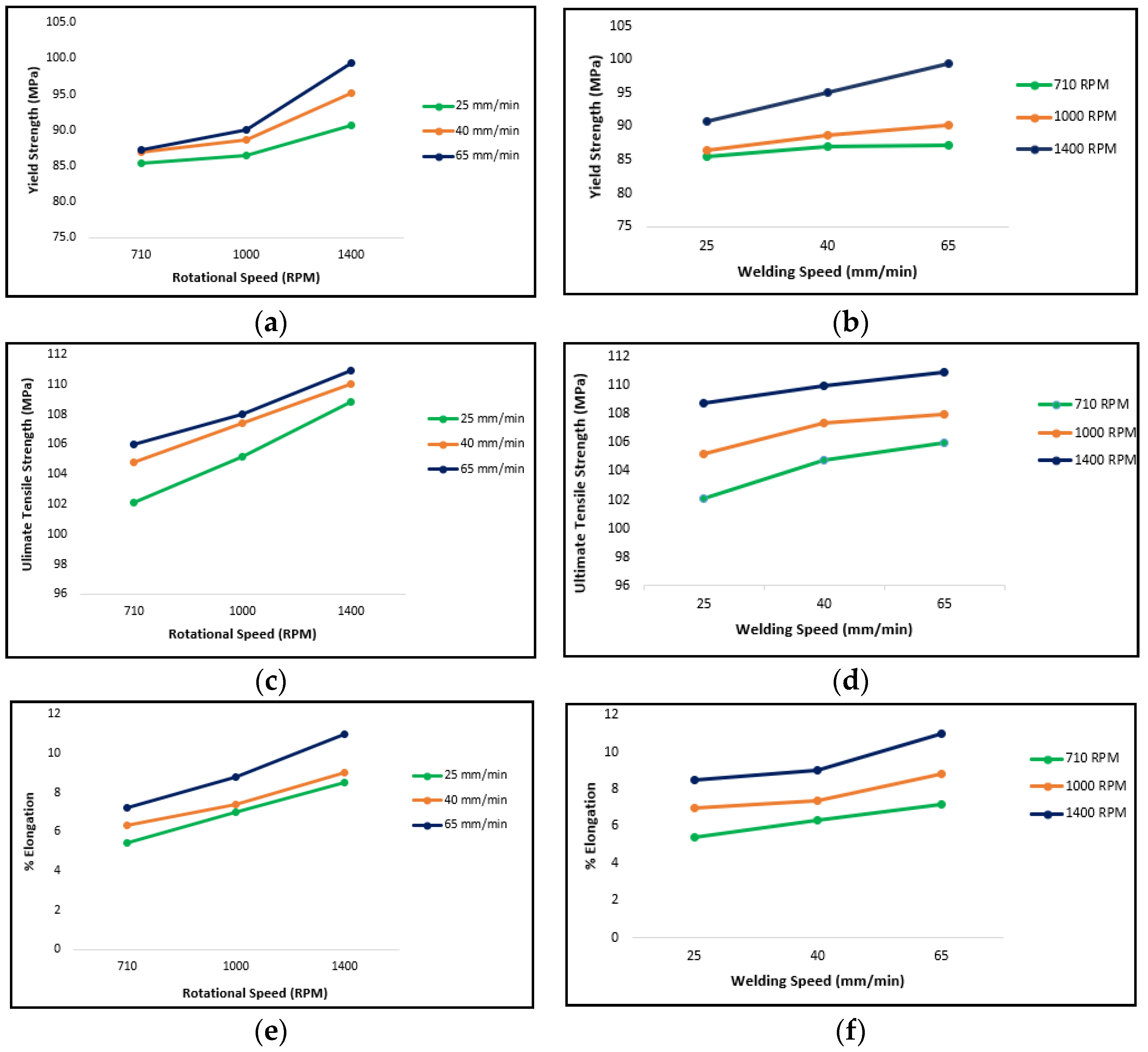
4.4.2. Impact of Tool Rotation Speed and Weld Speed on YS, UTS and % E

In FSW, at a higher tool rotation speed, more heat is generated. The heat helps to transform solid materials into semi-solid ones, which results in a proper fusion of two materials. However, if the tool rotation speed is very high and weld speed is lowered, extra heat is generated which creates a HAZ. Due to extra heat in the HAZ, the grain structure at the weld joint becomes coarse and brittle [30]. Thus, the HAZ is considered as a weak link in the weld joint and becomes prone to failure. Thus, when weld speed increases at a constant tool rotation speed and probe offset, tensile properties also improve [31]. The same was observed during the experimental study, as shown in Figure 12.
The Table 9 shows the summary of the impact of different welding variables on the mechanical properties of FSW weld joint.

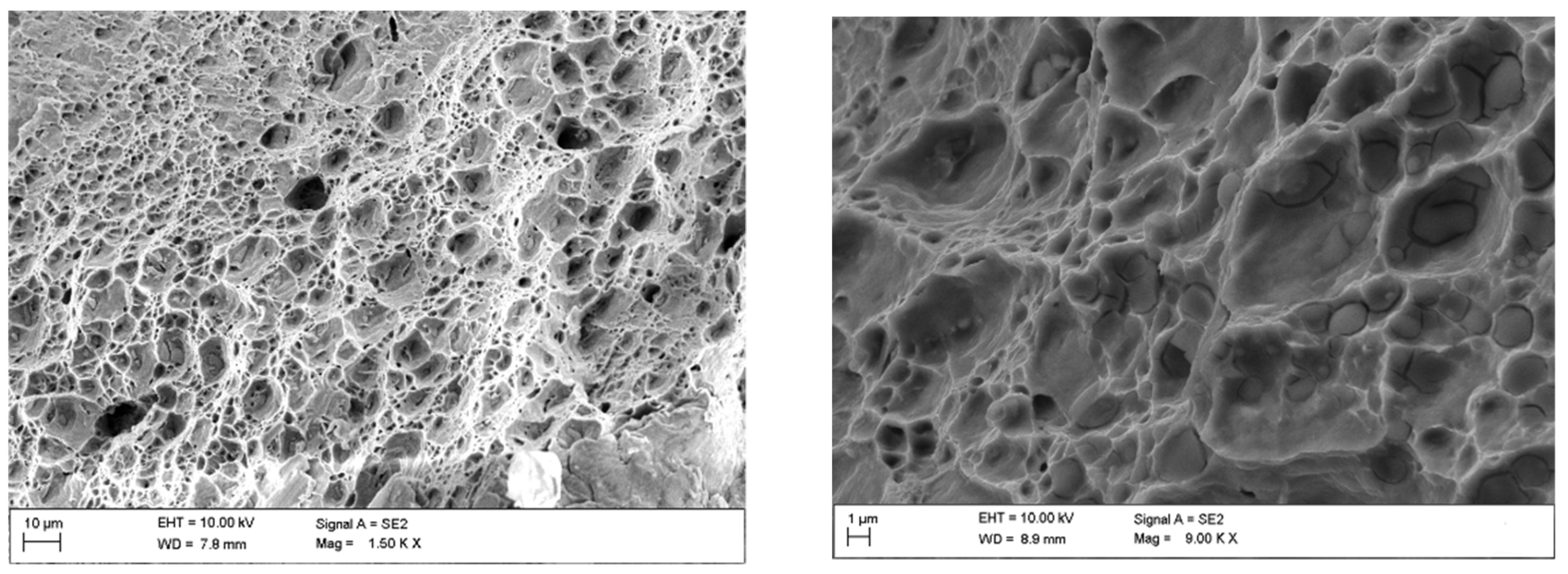
4.5. Analysis on Fracture Surface

Scanning electron microscopy was applied to examine the failure behavior of the fracture surfaces of the tensile specimens. From Figure 13, it can be seen that cup-and-cone style ridges and dips are present in the fracture surface. This specifies that the behavior of the failure mode is ductile [32]. In Figure 14, it can be observed that a cleavage-like feature is found on the fracture surface, which indicates that the weld failed through brittle facture [7]. Additionally, at the fracture surface of the welded joint, microscopic voids of different sizes and shapes, as well as large dimples can be observed. The formation of dimples reduces the ductility and weakens the weld joint [16]. Thus, it can be concluded that, when the tool offset is closer to the softer material, the joint becomes more ductile with a higher tensile strength.

5. Conclusions

In the current experimental study, an effort has been made to determine the feasibility of FSW for dissimilar materials: AA 6061-T6 and Cu B370. The findings of the experiments are follows.
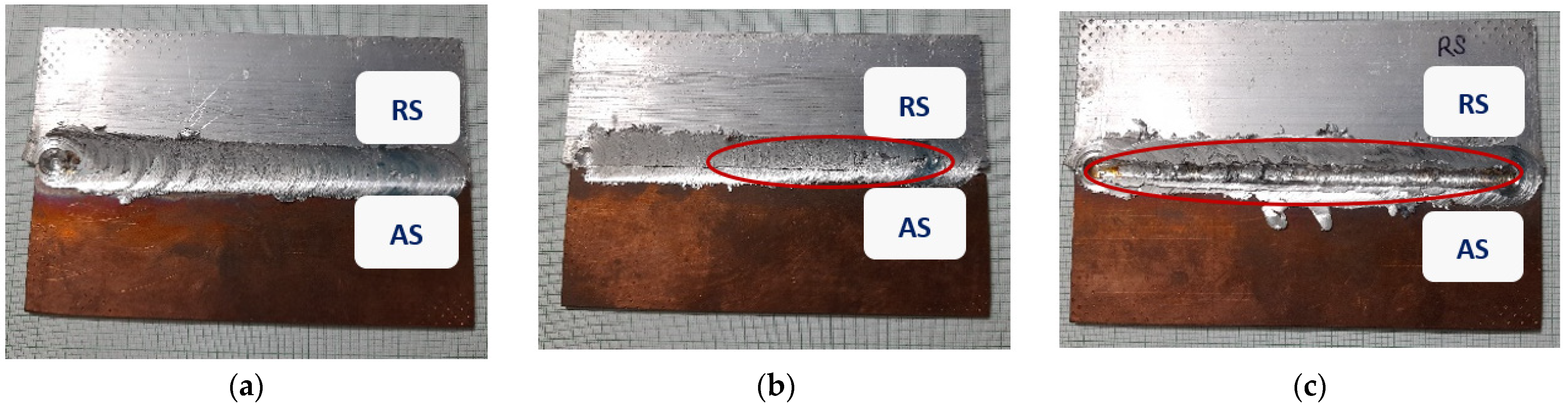
  • Dissimilar materials, AA 6061-T6 and Cu B370, were successfully joined using FSW at various tool rotation speeds, weld speeds, and probe offsets towards the softer material, Al, side.
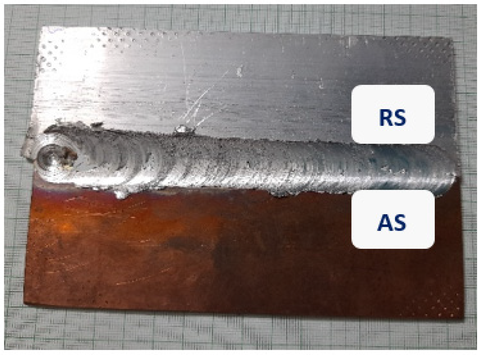
  • An excellent weld joint and surface was obtained at a probe offset of 2.0 mm towards the Al side and with the configuration of keeping the copper plate at the AS and the aluminum plate at the RS.
  • From the F-test of ANOVA and from scatter diagrams, it can be concluded that the formulated statistical (mathematical) model is suitable enough to predict the output responses at a 95% confidence level.
  • From the experimental investigations, it was observed that the maximum tensile properties were obtained at a higher tool rotation speed by keeping the weld speed constant. A similar behavior was observed at a higher weld speed by keeping the tool rotation speed constant.
  • From SEM morphologies of the fracture surfaces, it can be noted that when the probe offset is 2.0 mm, the failure mode is ductile in nature and the tensile properties are at their maximum. However, the tensile strength decreased as the probe offset became less. For a probe offset of 1.0 mm, the failure mode was found to be brittle in nature.

Author Contributions

B.B. has done the experimental part and all analysis part. She has drafted the initial paper. R.K. is in continuous correspondence with the first author during the research work. Second author reviewed the paper and with the consultation of first and third author, final format of the manuscript is prepared for submission. S.C. has done the final editing and put his critical comment in the improvement of the paper. S.B. done final editing of paper with the third author. All authors have read and agreed to the published version of the manuscript.

Funding

Not applicable.

Institutional Review Board Statement

Not applicable.

Informed Consent Statement

Not applicable.

Data Availability Statement

Not applicable.

Acknowledgments

The authors would like to extend their sincere gratitude to the Mechanical Engineering Department, and Friction Stir Welding Lab of IIT Kharagpur, India, for allowing us to conduct FSW experiments in their laboratory.

Conflicts of Interest

The authors declare no conflict of interest.

References

  1. Sharma, N.; Khan, Z.A.; Siddiquee, A.N. Friction stir welding of aluminum to copper—An overview. Trans. Nonferrous Met. Soc. China 2017, 27, 2113–2136. [Google Scholar] [CrossRef]
  2. Groover, M.P. Fundamentals of Modern Manufacturing Material. Processes and Systems, 7th ed.; John Wiley and Sons, Inc.: Hoboken, NJ, USA, 2019; pp. 657–663. [Google Scholar]
  3. Bora, B.; Kumar, R.; Chattopadhyaya, S. Friction Stir Welding: A Green Technology for Welding Joints with Dissimilar Metals (Al Alloy-Cu Alloy). J. Indian Chem. Soc. 2020, 97. in press. [Google Scholar]
  4. Bora, B.; Chattopadhyaya, S.; Kumar, R. Development of mathematical model for friction stir welded joint using ‘R’ Programming. Mater. Today Proc. 2020, 27, 2142–2146. [Google Scholar] [CrossRef]
  5. Mubiayi, M.P.; Akinlabi, E.T. Friction Stir Welding of Dissimilar Materials between Aluminium Alloys and Copper—An Overview. In Proceedings of the World Congress on Engineering (WCE), London, UK, 3–5 July 2013; Volume 3. [Google Scholar]
  6. Prabhu, L.; Kumar, S.S. Tribological characteristics of FSW tool subjected to joining of dissimilar AA6061-T6 and Cu alloys. Mater. Today Proc. 2020, 33, 741–745. [Google Scholar] [CrossRef]
  7. Sahu, S.K.; Haldar, N.; Datta, S.; Kumar, R. Experimental studies on AA6063-Cu dissimilar friction stir welding using Inconel 601 tool. Mater. Today Proc. 2020, 26, 180–188. [Google Scholar] [CrossRef]
  8. Kadian, A.K.; Biswas, P. The study of material flow behaviour in dissimilar material FSW of AA6061and Cu-B370 alloys plates. J. Manuf. Process. 2018, 34, 96–105. [Google Scholar] [CrossRef]
  9. Khojastehnezhad, V.M.; Pourasl, H.H. Microstructural characterization and mechanical properties of aluminum 6061-T6 plates welded with copper insert plate (Al/Cu/Al) using friction stir welding. Trans. Nonferrous Met. Soc. China 2018, 28, 415–426. [Google Scholar] [CrossRef]
  10. Shankar, S.; Vilaça, P.; Dash, P.; Chattopadhyaya, S.; Hloch, S. Joint strength evaluation of friction stir welded Al-Cu dissimilar alloys. Measurement 2019, 146, 892–902. [Google Scholar] [CrossRef]
  11. Montgomery, D.C. Design and Analysis of Experiments, 5th ed.; John Wiley and Sons, Inc.: Hoboken, NJ, USA, 2000; pp. 11–20. [Google Scholar]
  12. Kumar, K.P.V.; Balasubramanian, M. Analyzing the Effect of FSW Process Parameter on Mechanical Properties for a Dissimilar Aluminium AA6061 and Magnesium AZ31B Alloy. Mater. Today Proc. 2020, 22, 2883–2889. [Google Scholar] [CrossRef]
  13. Prasad, M.V.R.D.; Namala, K.K. Process Parameters Optimization in Friction Stir Welding by ANOVA. Mater. Today Proc. 2018, 5, 4824–4831. [Google Scholar] [CrossRef]
  14. Pandya, S.N.; Menghani, J. Developments of Mathematical Models for Prediction of Tensile Properties of Dissimilar AA6061-T6 to Cu Welds Prepared by Friction Stir Welding Process Using Zn Interlayer. Indian Acad. Sci. 2018, 43, 43–168. [Google Scholar] [CrossRef] [Green Version]
  15. Reddy, R.; Tandle, A.; Srikanth, S.; Singh, R.; Kolli, R. Design and Analysis of Friction Stir Welding Using Dissimilar Alloys (AA 6061 and AA 6082) Aluminum Alloys. Int. Res. J. Eng. Technol. IRJET 2018, 5, 138–147. [Google Scholar]
  16. Xue, P.; Ni, D.R.; Wang, D.; Xiao, B.L.; Ma, Z.Y. Effect of friction stir welding parameters on the microstructure and mechanical properties of the dissimilar Al–Cu joints. Mater. Sci. Eng. 2011, 528, 4683–4689. [Google Scholar] [CrossRef]
  17. Sahu, P.K.; Pal, S.; Pal, S.K.; Jain, R. Influence of plate position, tool offset and tool rotational speed on mechanical properties and microstructures of dissimilar Al/Cu friction stir welding joints. J. Mater. Process. Technol. 2016, 235, 55–67. [Google Scholar] [CrossRef]
  18. Hou, W.; Shah, L.H.A.; Huang, G.; Shen, Y.; Gerlich, A. The role of tool offset on the microstructure and mechanical properties of Al/Cu friction stir welded joints. J. Alloy. Compd. 2020, 825, 154045. [Google Scholar] [CrossRef]
  19. Zhang, S.; Shi, Q.; Liu, Q.; Xie, R.; Zhang, G.; Chen, G. Effects of tool tilt angle on the in-process heat transfer and mass transfer during friction stir welding. Int. J. Heat Mass Transf. 2018, 125, 32–42. [Google Scholar] [CrossRef]
  20. Dialami, N.; Cervera, M.; Chiumenti, M. Effect of the Tool Tilt Angle on the Heat Generation and the Material Flow in Friction Stir Welding. Metals 2019, 9, 28. [Google Scholar] [CrossRef] [Green Version]
  21. Wu, D.; Li, W.Y.; Gao, Y.J.; Yang, J.; Su, Y.; Wen, Q.; Vairis, A. Effect of an improved pin design on weld formability and mechanical properties of adjustable-gap bobbin-tool friction stir welded Al-Cu aluminum alloy joints. J. Manuf. Process. 2020, 58, 1182–1188. [Google Scholar] [CrossRef]
  22. Tan, C.W.; Jiang, Z.G.; Li, L.Q.; Chen, Y.B.; Chen, X.Y. Microstructural evolution and mechanical properties of dissimilar Al–Cu joints produced by friction stir welding. Mater. Des. 2013, 51, 466–473. [Google Scholar] [CrossRef]
  23. Muthu, M.F.X.; Jayabalan, V. Effect of pin profile and process parameters on microstructure and mechanical properties of friction stir welded Al−Cu joints. Trans. Nonferrous Met. Soc. China 2016, 26, 984–993. [Google Scholar] [CrossRef]
  24. Zhang, Q.; Gong, W.; Liu, W. Microstructure and mechanical properties of dissimilar Al−Cu joints by friction stir welding. Trans. Nonferrous Met. Soc. China 2015, 25, 1779–1786. [Google Scholar] [CrossRef]
  25. Sorger, G.; Wang, H.; Vilaça, P. FSW of aluminum AA5754 to steel DX54 with innovative overlap joint. Weld World 2017, 61, 257–268. [Google Scholar] [CrossRef] [Green Version]
  26. Lukács, J.; Meilinger, Á.; Pósalaky, D. High cycle fatigue and fatigue crack propagation design curves for 5754-H22 and 6082-T6 aluminium alloys and their friction stir welded joints. Weld World 2018, 62, 737–749. [Google Scholar] [CrossRef]
  27. Kumar, R.; Bora, B.; Chattopadhyaya, S.; Krolczyk, G.; Hloch, S. Experimental and mathematical evaluation of thermal and tensile properties of friction stir welded joint. Int. J. Mater. Prod. Technol. 2018, 57, 1–3. [Google Scholar] [CrossRef]
  28. Harry, M.J.; Mann, P.S.; de Hodgins, O.C.; Hulbret, R.L.; Lacke, C.J. The Practitioner’s Guide to Statistics and Lean Six Sigma For. Process. Improvement, 1st ed.; John Wiley and Sons, Inc.: Hoboken, NJ, USA, 2010; pp. 507–522. [Google Scholar]
  29. Palanivel, R.; Mathews, P.K.; Murugan, N. Development of mathematical model to predict the mechanical properties of friction stir welded AA6351 aluminum alloy. J. Eng. Sci. Technol. 2011, 4, 25–31. [Google Scholar] [CrossRef]
  30. Singh, K.; Singh, G.; Singh, H. Investigation of microstructure and mechanical properties of friction stir welded AZ61 magnesium alloy joint. J. Magnes. Alloy. 2018, 6, 292–298. [Google Scholar] [CrossRef]
  31. Kumar, G.; Kumar, R.; Kumar, R. Optimization of process parameters of friction stir welded AA5082-AA7075 butt joints using resonance fatigue properties. Bull. Pol. Acad. Sci. Tech. Sci. 2020, 68, 99–108. [Google Scholar]
  32. Yang, J.; Ni, D.R.; Wang, D.; Xiao, B.L.; Ma, Z.Y. Friction stir welding of as-extruded Mg–Al–Zn alloy with higher Al content. Part I: Formation of banded and line. Mater. Charact. 2014, 96, 142–150. [Google Scholar] [CrossRef]
Figure 1. Schematic diagram of FSW [4].
Applsci 11 04604 g001
Figure 2. FSW tool.
Figure 2. FSW tool.
Applsci 11 04604 g002
Figure 3. FSW tool geometry.
Applsci 11 04604 g003
Figure 4. Experimental set-up—linear numerically controlled FSW machine (ETA, WS004).
Applsci 11 04604 g004
Figure 5. Pictorial view of the FSW joint after the welding process.
Applsci 11 04604 g005
Figure 6. Tensile test specimen (sample no. 6).
Applsci 11 04604 g006
Figure 7. (ac) Scatter diagrams of output responses—tensile properties (YS, UTS, % E).
Applsci 11 04604 g007aApplsci 11 04604 g007b
Figure 8. FSW weld joint with Cu (AS) and Al (RS).
Applsci 11 04604 g008
Figure 9. FSW weld joint with Cu (RS) and Al.
Applsci 11 04604 g009
Figure 10. Surface morphologies of welded joints at tool offsets of (a) 2 mm, (b) 1.5 mm, and (c) 1 mm at a rotational speed of 1400 RPM and welding speed of 65 mm/min.
Applsci 11 04604 g010
Figure 11. UTS of weld joint with different probe offset values.
Applsci 11 04604 g011
Figure 12. (a) Tool RPM Vs. YS, (b) Weld Speed Vs. YS, (c) Tool RPM Vs. UTS, (d) Weld Speed Vs. UTS, (e) Tool RPM Vs. % E, and (f) Weld Speed Vs. % E.
Applsci 11 04604 g012
Figure 13. SEM morphology of fracture surface: process parameters = 1400 RPM, 65 mm/min, and probe offset = 2.0 mm.
Applsci 11 04604 g013
Figure 14. SEM morphology of fracture surface: process parameter = 1400 RPM, 65 mm/min, and probe offset = 1.0 mm.
Applsci 11 04604 g014
Table 1. Chemical composition.
(a) AA 6061-T6
ElementMgSiFeCuCrZnTiMnAl
Composition (weight%)1.070.580.540.320.130.140.130.0796.97
(b) Cu B370
ElementCuAg
Composition (weight%)99.7Balance
Table 2. Mechanical properties of AA 6061-T6 and Cu B370.
Mechanical PropertyAA 6061-T6Cu B370
Ultimate tensile strength310 MPa260 MPa
Yield strength276 MPa205 MPa
Modulus of elasticity68.9 GPa115 GPa
Table 3. Dimension of FSW tool.
ParametersValue (mm)
Shank height70
Shank diameter20
Shoulder height 30
Shoulder diameter (2R1)25 mm
Pin top diameter (2R2)6 mm
Pin bottom diameter (2R3)4 mm
Pitch of threads0.1
Height of pin (H)2.7
Tool tilt angle (α)20.3°
Table 4. Different welding variables.
Tool Rotation Speed (RPM)Weld Speed (mm/min)Probe Offset (mm)
1400651.0
1000401.5
710252.0
Table 5. Design of experiments.
Sample No.Tool Rotation Sped (RPM)Weld Speed (mm/min)
1140040
2100040
371040
4100025
5140025
6140065
7100065
871025
971065
Table 6. Experimental data of the tensile properties (YS, UTS, % E).
Sample No.Tool Rotation Speed (RPM)Weld Speed (mm/min)YS (MPa)UTS (MPa)% EFracture Location
614006599.4110.911SZ/TMAZ
114004095.11109SZ/TMAZ
514002590.7108.88.5SZ/TMAZ
710006590.11088.8SZ/TMAZ
210004088.7107.47.4HAZ
410002586.5105.27HAZ
97106587.21067.2HAZ
37104087104.86.3HAZ
87102585.4102.15.4HAZ
Table 7. Statistical model—ANOVA test results.
OutcomesDFSSMSCalculated F Value Tabulated F ValueRemarks
RegressionResidualRegressionResidualRegressionResidual
YS26146.37120.43873.18573.18521.485.14Adequate
UTS2658.9012.79429.4510.46663.235.14Adequate
% E2621.8970.42510.9490.071154.565.14Adequate
Table 8. Analysis of variance for test results of tensile properties.
I For YS (MPa)
SourceDFSSMSFP
Tool Rotation Speed2120.42960.214418.600.009
Weld Speed233.42916.71445.160.078
Error412.9513.2378
Total8166.809
S = 1.799; R-Sq = 92.24%; R-Sq (adj) = 84.47%
II For UTS (MPa)
SourceDFSSMSFP
Tool Rotation Speed 247.148923.574494.510.000
Weld Speed213.54896.774427.160.005
Error40.99780.2494
Total861.6956
S = 0.4994; R-Sq = 98.38%; R-Sq (adj) = 96.77%
III For % Elongation
SourceDFSSMSFP
Tool Rotation Speed 215.41567.7077886.170.001
Weld Speed26.54893.2744436.610.003
Error40.35780.08944
Total822.3222
S = 0.2991; R-Sq = 98.40%; R-Sq (adj) = 96.79%
Table 9. Summary on the impact of welding variables on mechanical properties.
Welding VariablesValuesImpact on Mechanical Properties
Tool probe offset (mm)
(at constant tool rotational speed and weld speed)
1.0 Applsci 11 04604 i001
1.5 Applsci 11 04604 i001
2.0 Applsci 11 04604 i002
Tool rotational speed (RPM)
(at constant weld speed and tool probe offset)
710 Applsci 11 04604 i001
1000 Applsci 11 04604 i001
1400 Applsci 11 04604 i002
Weld speed (mm/min)
(at constant tool rotational speed and tool probe offset)
25 Applsci 11 04604 i001
40 Applsci 11 04604 i001
65 Applsci 11 04604 i002
Publisher’s Note: MDPI stays neutral with regard to jurisdictional claims in published maps and institutional affiliations.

