Abstract
In this paper, we discuss two problems concerning scattering and localisation of flexural waves in structured elastic plates. Firstly, we compare the scattering amplitudes of waves in a thin plate, generated by a point source, due to a single mass and to a large number of smaller masses, having the same equivalent mass and located around a circle. We show that in the second case, the scattering can be reduced, in particular in the medium- and high-frequency regimes. Secondly, we develop a homogenised model for a double-ring cluster of spring-mass resonators, connected to an elastic thin plate. We determine the conditions for which the plate exhibits vibration modes trapped between the two rings. Further, we show that the frequencies of the localised modes can be tuned by varying the geometry of the two rings and the characteristics of the resonators. The analytical results are corroborated by numerical simulations performed with independent finite element models.
1. Introduction
In recent years, mathematical and physical problems related to wave localisation and scattering by discrete clusters have attracted increasing interest in the scientific community. In fact, the study of localised waveforms in structured media and dynamic Green’s kernels in lattices is essential in the analysis of defects in crystalline solids, transmission resonances for grating stacks, and novel designs of wave shields or “cloaks”.
The notion of a Faraday cage, representing a device capable of protecting a bounded domain from an external electric field [1], is well established in electromagnetism. This notion has been extended to acoustic waves, governed by the Helmholtz equation, in [2]. In elasticity, the localisation of elastic waves in solids with clusters of defects, such as small inertial inclusions or rigid pins, exhibits new features in the mathematical description and physical interpretation of the phenomena; in particular, it is known that structured flexural plates incorporate evanescent and propagating waveforms, which couple through the boundary conditions. The dynamics of imperfect crystals with point defects has been extensively analysed in [3,4]. Propagation of waves in square lattices, generated by oscillating a lattice point in the out-of-plane direction, has been investigated in [5], while localised vibrations in band-gaps of continuous and discrete structures, obtained from the Green’s function approach, have been examined in [6].
In elastic plates, localisation and transmission of flexural waves due to a periodic arrangement of rigid pins or point masses have been analysed in [7,8,9]. Unidirectional trapped modes, associated with Dirac points in the dispersion diagrams, have been shown to exist in thin plates with a finite cluster of pins [10]. Cloaking of a rigid inclusion in a Kirchhoff plate by means of active sources has been proposed in [11]. Localisation in semi-infinite grating stacks of rigid pins or resonators has been investigated in [12,13]. A platonic structure with spiral resonators has been presented in [14], with special emphasis on applications such as low-frequency filtering, transmission amplification and generation of edge waves. In [15], resonating beams arranged in concentric circles were connected to a plate to create a directional cloak. Time-harmonic waves produced by an external force in a thin plate with attached masses were studied in [16]. The band structures of thin and thick plates incorporating periodic arrays of spring-mass resonators were discussed in [17,18]. The existence of band gaps in plates with different types of cavities has been numerically and experimentally demonstrated in [19,20]. The low-frequency vibrations and radiation performance of homogeneous and sandwich plates containing periodically distributed resonators have been investigated in [21,22]. Effective band-gaps and wave conversion in plates have been obtained in [23] by inserting a periodic array of perpendicular rod-like resonators. Gyroscopic resonators attached to plates have been employed in [24,25] to create flexural waveforms propagating in one direction. Topologically protected edge and interfacial modes in microstructured plates have also been discovered in [26,27,28,29].
An asymptotic analysis has been developed in [30,31] to describe Bloch modes localised around a circular array of inclusions, showing similarities with whispering gallery modes. The analysis has been carried out for the planar Helmholtz equation and assuming Neumann boundary conditions at the boundaries of the inclusions. Recently, an asymptotic homogenised model for the bi-harmonic operator was presented in [32] to predict the existence of flexural vibrations confined along a ring of spring-mass resonators, which yield “negative inertia” in the dynamic regime. In that model, the frequency of the localised flexural modes along the ring could not be chosen ad libitum. Graded rings of point masses on a thin plate have been considered in [33] to describe new applications of rainbow trapping and wave hybridisation effects.
A classical approach [34] can be used to study the scattering of a time-harmonic wave by a cluster of small defects. We go further, and in this paper, we build upon the results developed in [32], constructing a novel asymptotic model, which describes the trapping of flexural waves in an elastic plate by a two-ring cluster of point resonators. Each individual resonator may have positive or negative inertia, as in [12,32], respectively, and the frequency of a trapped waveform can be controlled by tuning the inertia of the resonators and through the dynamic coupling between the vibrations of two circular clusters. Since, in this case, the frequency of the localised vibrations can be chosen a priori, this model offers more versatility than that described in [32]. Furthermore, in Section 3.1, we demonstrate that the scattering by a point mass M can be reduced if the latter is replaced by a ring of smaller masses with total mass M.
An illustrative example of the capabilities of the asymptotic model presented in this paper to predict the occurrence of localised vibrations is shown in Figure 1. The radian frequency of the localised mode in the plate is chosen arbitrarily, and the geometry of the rings and the properties of the resonators are determined accordingly, as discussed in Section 3.2. In part (a) and (b), the mode number is and , respectively. From the figure, it is apparent that vibrations are highly localised between the two rings of spring-mass resonators.

Figure 1.
Localised modes in an elastic plate, containing two concentric rings of spring-mass resonators, obtained for rad/s and for (a) and (b) . In the calculations, the plate is assumed to be made of aluminium (Young’s modulus GPa, Poisson’s coefficient and mass density kg/m) and to have a thickness m. The radii of the two rings are m and m, and the total masses of the resonators are (a) kg and kg and (b) kg and = 10,609.7 kg.
2. Analytical Methods
2.1. Scattering Reduction of Flexural Waves in a Thin Plate by a Finite Cluster of Masses
We begin with an elementary example, where a point scatterer, represented by a single mass M and incorporated in a thin plate, is replaced by a finite cluster of smaller masses () such that . Here, the masses are placed at points () along a circle of radius R centred at the origin (see Figure 2).
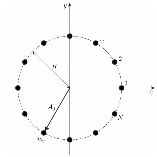
Figure 2.
Finite cluster of N masses , attached to an elastic plate and located along a circle of radius R. The total mass is given by M.
2.1.1. The Incident Field
Assuming that the incident field is induced by a remote point source, we demonstrate that the overall scattering produced by the cluster of equivalent mass M can be significantly smaller compared to the scattering associated with the single point mass M.
Let be the Green’s function representing a flexural wave in an infinite isotropic Kirchhoff plate produced by a time-harmonic point source at the origin:
where
with , h and being the mass density, the plate thickness and the radian frequency, respectively. The quantity is the flexural rigidity of the plate, with E being the Young’s modulus and being the Poisson’s ratio.
The Green’s function G has the form [35,36,37]
We note that the above Green’s function is bounded at the origin, and
Given (2), we consider the incident field of the form
which implies that the wave is generated by the time-harmonic motion of a point at with displacement amplitude U and radian frequency
2.1.2. Scattering by an Inertial Cluster
The total flexural displacement field has the form
where the coefficients () are connected to the inertia of the point masses as follows:
In particular, when the scattering is produced by the single point mass M positioned at the origin, we have
and hence the amplitude of the time-harmonic vibrations at the origin is
We also note that when while the frequency of the incident wave is fixed, we obtain the case of a scattering by a rigid pin positioned at the origin.
On the other hand, for the ring-shaped finite cluster of N point masses, shown in Figure 2, with the flexural displacement defined by (4), the amplitudes () of time-harmonic flexural displacements satisfy the system of linear algebraic equations
which is consistent with the classical Foldy approach for scattering problems in domains with finite clusters of point defects [34].
2.2. Trapped Vibrations in a Double-Ring Cluster of Point Resonators
The previous example, constructed for a finite cluster, leads to a conjecture suggesting a localisation of the elastic field around the cluster. We consider a double ring of point resonators in a thin plate and assume that their number is large so that the homogenisation approximation, similar to [32], can be applied for selected frequency regimes.
The main feature of the new model with respect to the study in [32] is the wave-coupling between the two rings of point resonators. Although we use the term “mass”, the inertia of each individual resonator can be either positive or negative. As discussed in [32], negative inertia in the dynamic regime can be attained by connecting a mass to the flexural plate through an elastic spring.
2.2.1. Homogenised Problem for a Double-Ring Cluster
Formally, we look for a localised waveform (no incident field) of radian frequency , with the flexural displacement field satisfying the equation
where D, and h represent the flexural stiffness, the mass density and the thickness of the elastic isotropic plate, respectively, as in Section 2.1. Here, the notations and are used for the concentric circles of radii and , namely
and
The quantity () in (9) denotes the mass of the point resonator in the ring defined by () (see Figure 3). It is assumed that the number of point resonators is large, i.e., , but the combined masses of inertial clusters placed along the circles and are finite:

Figure 3.
Plate incorporating a double-ring of masses or spring-mass resonators.
For the displacement we use the representation (4), with the term being replaced by zero. At the nodal points and (), Equation (8) is replaced by
Similar to [32], in the limit when , the sums in the right-hand sides of (10) and (11) are approximated by the integrals. Using the notations for two points on the circles (), we write the system of boundary integral equations in the form
where the position vectors of the points on can be represented in the complex form
The flexural displacement is sought in the form
We also take into account the identity
Here, the integer number q determines the order of the trapped flexural vibration mode.
Using the notation for the matrix of the above linear system, the equation for the spectral parameter is
The components of the matrix are
We note that the off-diagonal terms and tend to zero when , or , and hence the analysis of these limit configurations is reduced to the case of trapped modes in a single ring of resonators, as studied in [32].
2.2.2. Evaluation of the Integrals in the Secular Equation
The integrals in (13) and (14) and in the secular Equation (15) can be evaluated in the closed analytical form.
We have two rings with radii and , and assume . Let and denote polar angles on the two rings. The integral we will evaluate analytically is:
Here, the Green’s function G for the biharmonic problem is
The tool we use in the evaluation is Graf’s addition theorem (see Section 10.23 of [38] and [39]). This can be written for (length, angle) pairs , , :
and
Here, is an integer, and is assumed.
In applying this to G, we need only the case :
and
Carrying out the integral over , the result is:
This obeys the symmetry relation . We have derived (27) for real, but it can be extended to complex by analytic continuation.
We can also consider
Then it follows from the symmetry rule just given that .
The remaining integrals to calculate are
and
These agree with the results quoted in [32].
2.2.3. Frequency of Localised Waveforms
The secular equation has the form:
where the parameter dependence of the integrals has been abbreviated for brevity. We get simple results if we fix all other parameters and regard and as the variables to be found.
3. Results and Discussion
3.1. Scattering Problem
In the numerical examples, we assume that , so that all point masses placed along the circle are equal, and we also assume that they split the circle into N arcs of equal length. It is also apparent that the force produced by an individual source associated with one point mass is determined by the inertia of this point mass.
It would not be surprising if splitting the mass M into several small masses and aligning them along the symmetry axis of the incident wave reduces scattering in certain frequency regimes. However, this can also be achieved if the total mass M is split into smaller masses distributed along a circle, as demonstrated in Figure 4.
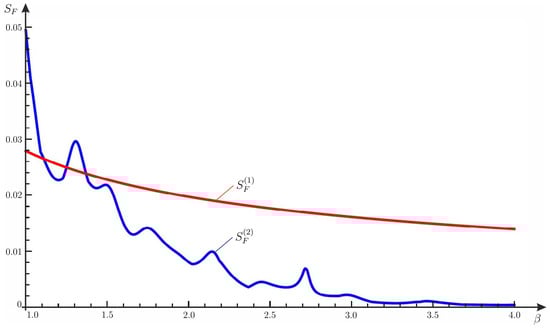
Figure 4.
Comparison of the reaction forces produced by a single mass scatterer and by a circular cluster of 12 point mass scatterers of the same combined mass. The incident field is produced by a point source. The data, referred to units, used in the computation are , , , . The graph compares for a point scatterer of mass 600 (red) with for a cluster of 12 points, each of mass 50, on the ring of radius R (blue). The point scatterer appears to scatter more strongly at higher frequencies, as illustrated by the computation.
For the single scatterer, we measure
whereas for the cluster of smaller scatterers of the same total mass, we measure
It is shown in Figure 4 that, in the chosen frequency regime, the total force generated by the cluster of point scatterers of total mass M is significantly smaller than the reaction force produced by a single point mass of the same mass M.
3.2. Trapped Modes
Here, we show how to obtain localised modes in the plate, confined between the two concentric rings of point resonators.
The procedure is the following. We choose the radian frequency of the localised mode and the mode number q. We fix the geometry of the rings, in particular the radii and and the number N of resonators. In particular, in the calculations, we take , which is sufficiently large to apply the homogenisation approach described in Section 2.2. Then, we calculate the total mass from Equation (33) and, successively, the total mass from Equation (32).
An example has been illustrated in Figure 1 of the Introduction. The values of the geometrical and constitutive parameters are detailed in the caption of the figure. The localised modes corresponding to two values of the mode number q have been presented, namely in part (a) and in part (b). The total masses of the rings, and , are obviously different in the two cases examined.
In order to check the accuracy of the analytical formulation and the validity of the homogenisation approximation, we have also performed numerical simulations in Comsol Multiphysics 5.5 [40]. Since the numerical model needs to have a finite domain, we have considered a square plate with side length m. The localised modes for rad/s and for (part (a)) and (part (b)) are presented in Figure 5. Comparing Figure 1 and Figure 5, we notice a very good agreement between analytical and numerical results.

Figure 5.
Same as in Figure 1, but obtained numerically with a finite element code built in Comsol Multiphysics. The mode number is (a) and (b) . In the simulations, the side length of the plate is m.
The displacement fields evaluated along the two perpendicular directions and , shown in Figure 5, are given in Figure 6 for and in Figure 7 for . The solid lines represent the analytical results derived from the homogenisation approximation described in the previous sections, while the dots indicate the data obtained numerically from Comsol Multiphysics. The comparison shows once again that the analytical and numerical models produce very similar results.

Figure 6.
Displacements in the plate for , determined along the direction cutting two maxima (a) and along the perpendicular direction (b). The solid lines represent the analytical results, while the dots are the numerical outcomes provided by Comsol Multiphysics.

Figure 7.
Same as in Figure 6, but determined for . The displacements are evaluated (a) in the direction and (b) along the perpendicular direction .
In Figure 8, we show how to extrapolate the total masses of the two rings, and , for different values of the radius of the external ring. In the plots, the radius of the internal ring is fixed ( m) and the mode number is (part (a)) and (part (b)). The total masses and considered in Figure 1 and Figure 5, corresponding to m, are indicated by dots.

Figure 8.
Total mass in the internal ring (left) and total mass in the external ring (right) calculated for different values of the radius of the external ring and for (a) and (b) . The radius of the internal ring is m and the frequency of the localised mode is rad/s, as in Figure 1 and Figure 5. The dots represent the values of the total masses determined in Figure 1 and Figure 5.
In the left diagrams of Figure 9, we present the first four frequencies of the localised modes as functions of the ratio between the radii of the two concentric circles, for (part (a)) and (part (b)). In the right diagrams, the corresponding values of the ratio between the total masses of the rings are included. The possibility to change the frequency at which a localised mode occurs demonstrates the versatility of the approach developed in this paper. We also note that when , the diagrams give the frequencies of a single ring, with total mass , discussed in [32].

Figure 9.
Frequencies of localised modes (left) and ratios of total masses (right) as functions of the ratio between the radii of the two rings, calculated for (a) and (b) . For any ratio , the first four solutions (labelled as a, b, c and d) are shown and indicated by dots. In the computations, m and (a) kg and (b) = 10,609.7 kg, as in Figure 1 and Figure 5. The crosses represent the values of the frequencies and the mass ratios obtained in Figure 1 and Figure 5.
4. Conclusions
In this paper, we have studied the effect of rings of point resonators on the dynamic behaviour of a thin elastic plate, modelled as a Kirchhoff plate.
First, we have demonstrated that the scattering produced by a single point mass M can be decreased significantly if that mass is split into a large number of smaller masses, arranged along a circle. This is especially true for medium and high frequencies.
Second, we have constructed an asymptotic model for two rings of spring-mass resonators attached to an elastic plate. This model allows determining the frequencies at which localised modes, confined between the two rings, can occur in the structure. We have also outlined the systematic procedure to vary the frequency of the trapped modes and to accordingly determine the geometrical and constitutive parameters of the two rings of resonators. In addition, we have verified the analytical results with an independent finite element code.
It is noted that for high frequencies, the discrete nature of the structure plays a significant role, and the relative rotation of the rings of point masses may be of interest. In particular, when the distance between the rings becomes small, the system involves a structure of dipoles of different orientations. In problems of wave scattering, such systems can also be viewed as inertial interfaces.
We envisage that the results of this work will be useful in the design of scattering systems and energy absorbers in structures supporting the propagation of flexural waves. We also note that the inertial double ring of point masses (or resonators) is a structured inertial interface system, and the homogenisation procedure can also address the discontinuity of tractions across such an interface for certain regimes of scattering of time-harmonic flexural waves.
Author Contributions
Conceptualisation, A.B.M. and R.C.M.; analytical methodology, A.B.M. and R.C.M.; numerical validation, G.C.; writing—original draft preparation, A.B.M. and G.C.; writing—review and editing, A.B.M., R.C.M. and G.C. All authors have read and agreed to the published version of the manuscript.
Funding
The authors would like to acknowledge the support of the Liverpool Research Centre for Mathematics and Modelling (RCMM) for the academic visits of R.C.M. to the University of Liverpool. At the initial stage of analysis leading to this paper, the work was supported by the UK Engineering and Physical Sciences Research Council Programme grant EP/L024926/1; EPSRC support is gratefully acknowledged.
Institutional Review Board Statement
Not applicable.
Informed Consent Statement
Not applicable.
Data Availability Statement
Data will be provided upon request to the authors.
Conflicts of Interest
The authors declare no conflict of interest.
References
- Kraus, J.D. Electromagnetics, 4th ed.; McGraw-Hill: New York, NY, USA, 1992. [Google Scholar]
- Martin, P. On acoustic and electric Faraday cages. Proc. R. Soc. Lond. A 2014, 470, 20140344. [Google Scholar] [CrossRef]
- Maradudin, A.A. Some effects of point defects on the vibrations of crystal lattices. Rep. Prog. Phys. 1965, 28, 331–380. [Google Scholar] [CrossRef]
- Maradudin, A.A.; Lifshitz, I.; Kosevich, A.; Cochran, W.; Musgrave, M. Lattice Dynamics; Benjamin: New York, NY, USA, 1969. [Google Scholar]
- Martin, P.A. Discrete scattering theory: Green’s function for a square lattice. Wave Motion 2006, 43, 619–629. [Google Scholar] [CrossRef]
- Movchan, A.B.; Slepyan, L.I. Band gap Green’s functions and localised oscillations. Proc. R. Soc. Lond. A 2007, 463, 2709–2727. [Google Scholar]
- Evans, D.V.; Porter, R. Penetration of flexural waves through a periodically constrained thin elastic plate in vacuo and floating on water. J. Eng. Math. 2007, 58, 317–337. [Google Scholar] [CrossRef]
- Haslinger, S.G.; Movchan, N.V.; Movchan, A.B.; McPhedran, R.C. Transmission, trapping and filtering of waves in periodically constrained elastic plates. Proc. R. Soc. Lond. A 2012, 468, 76–93. [Google Scholar] [CrossRef]
- Poulton, C.G.; Movchan, A.B.; Movchan, N.V.; McPhedran, R.C. Analytic theory of defects in periodically structured elastic plates. Proc. R. Soc. Lond. A 2012, 468, 1196–1216. [Google Scholar] [CrossRef]
- McPhedran, R.C.; Movchan, A.B.; Movchan, N.V.; Brun, M.; Smith, M.J.A. ‘Parabolic’ trapped modes and steered Dirac cones in platonic crystals. Proc. R. Soc. Lond. A 2015, 471, 20140746. [Google Scholar] [CrossRef] [PubMed]
- O’Neill, J.; Selsil, Ö.; McPhedran, R.C.; Movchan, A.B.; Movchan, N.V. Active cloaking of inclusions for flexural waves in thin elastic plates. Q. J. Mech. Appl. Math. 2015, 68, 263–288. [Google Scholar] [CrossRef]
- Haslinger, S.G.; Movchan, N.V.; Movchan, A.B.; Jones, I.S.; Craster, R.V. Controlling flexural waves in semi-infinite platonic crystals with resonator-type scatterers. Q. J. Mech. Appl. Math. 2017, 70, 216–247. [Google Scholar] [CrossRef]
- Haslinger, S.G.; Jones, I.S.; Movchan, N.V.; Movchan, A.B. Localisation in semi-infinite herringbone waveguides. Proc. R. Soc. Lond. A 2018, 474, 20170590. [Google Scholar]
- Morvaridi, M.; Carta, G.; Brun, M. Platonic crystal with low-frequency locally-resonant spiral structures: Wave trapping, transmission amplification, shielding and edge waves. J. Mech. Phys. Solids 2018, 121, 496–516. [Google Scholar] [CrossRef]
- Colombi, A.; Roux, P.; Guenneau, S.; Rupin, M. Directional cloaking of flexural waves in a plate with a locally resonant metamaterial. J. Acoust. Soc. Am. 2015, 137, 1783. [Google Scholar] [CrossRef] [PubMed]
- Martin, P.A.; Hull, A.J. Dynamic response of an infinite thin plate loaded with concentrated masses. Wave Motion 2020, 98, 102643. [Google Scholar] [CrossRef]
- Miranda, E.J.P., Jr.; Nobrega, E.D.; Ferreira, A.H.R.; Dos Santos, J.M.C. Flexural wave band gaps in a multi-resonator elastic metamaterial plate using Kirchhoff-Love theory. Mech. Syst. Signal Process. 2019, 116, 480–504. [Google Scholar] [CrossRef]
- Miranda, E.J.P., Jr.; Nobrega, E.D.; Rodrigues, S.F.; Aranas, C., Jr.; Dos Santos, J.M.C. Wave attenuation in elastic metamaterial thick plates: Analytical, numerical and experimental investigations. Int. J. Solids Struct. 2020, 204, 138–152. [Google Scholar] [CrossRef]
- Miniaci, M.; Marzani, A.; Testoni, N.; De Marchi, L. Complete band gaps in a polyvinyl chloride (PVC) phononic plate with cross-like holes: Numerical design and experimental verification. Ultrasonics 2015, 56, 251–259. [Google Scholar] [CrossRef]
- Kherraz, N.; Radzieński, M.; Mazzotti, M.; Kudela, P.; Bosia, F.; Gliozzi, A.S.; Misseroni, D.; Pugno, N.M.; Ostachowicz, W.; Miniaci, M. Experimental full wavefield reconstruction and band diagram analysis in a single-phase phononic plate with internal resonators. J. Sound Vib. 2021, 503, 116098. [Google Scholar] [CrossRef]
- Qin, Q.; Sheng, M.; Guo, Z. Low-Frequency Vibration and Radiation Performance of a Locally Resonant Plate Attached with Periodic Multiple Resonators. Appl. Sci. 2020, 10, 2843. [Google Scholar] [CrossRef]
- Guo, Z.; Pan, J.; Sheng, M. Vibro-Acoustic Performance of a Sandwich Plate with Periodically Inserted Resonators. Appl. Sci. 2019, 9, 3651. [Google Scholar] [CrossRef]
- Colquitt, D.J.; Colombi, A.; Craster, R.V.; Roux, P.; Guenneau, S. Seismic metasurfaces: Sub-wavelength resonators and Rayleigh wave interaction. J. Mech. Phys. Solids 2017, 99, 379–393. [Google Scholar] [CrossRef]
- Carta, G.; Colquitt, D.J.; Movchan, A.B.; Movchan, N.V.; Jones, I.S. One-way interfacial waves in a flexural plate with chiral double resonators. Philos. Trans. R. Soc. A 2019, 378, 20190350. [Google Scholar] [CrossRef] [PubMed]
- Carta, G.; Colquitt, D.J.; Movchan, A.B.; Movchan, N.V.; Jones, I.S. Chiral flexural waves in structured plates: Directional localisation and control. J. Mech. Phys. Solids 2020, 137, 103866. [Google Scholar] [CrossRef]
- Pal, R.K.; Ruzzene, M. Edge waves in plates with resonators: An elastic analogue of the quantum valley Hall effect. New J. Phys. 2017, 19, 025001. [Google Scholar] [CrossRef]
- Miniaci, M.; Pal, R.K.; Morvan, B.; Ruzzene, M. Experimental Observation of Topologically Protected Helical Edge Modes in Patterned Elastic Plates. Phys. Rev. X 2018, 8, 031074. [Google Scholar] [CrossRef]
- Makwana, M.P.; Craster, R.V. Designing multidirectional energy splitters and topological valley supernetworks. Phys. Rev. B 2018, 98, 235125. [Google Scholar] [CrossRef]
- Ungureanu, B.; Makwana, M.P.; Craster, R.V.; Guenneau, S. Localizing Elastic Edge Waves via the Topological Rainbow Effect. Phys. Rev. Appl. 2021, 15, 014057. [Google Scholar] [CrossRef]
- Maling, B.; Craster, R.V. Whispering Bloch modes. Proc. R. Soc. Lond. A 2016, 472, 20160103. [Google Scholar] [CrossRef] [PubMed]
- Maling, B.; Schnitzer, O.; Craster, R.V. Radiation from structured-ring resonators. SIAM J. Appl. Math. 2017, 77, 1047–1067. [Google Scholar] [CrossRef][Green Version]
- Movchan, A.B.; McPhedran, R.C.; Carta, G.; Craster, R.V. Platonic localisation: One ring to bind them. Arch. Appl. Mech. 2019, 89, 521–533. [Google Scholar] [CrossRef]
- Chaplain, G.J.; Makwana, M.P.; Craster, R.V. Rayleigh–Bloch, topological edge and interface waves for structured elastic plates. Wave Motion 2019, 86, 162–174. [Google Scholar] [CrossRef]
- Foldy, L.L. The multiple scattering of waves. I. General theory of isotropic scattering by randomly distributed scatterers. Phys. Rev. 1945, 67, 107–119. [Google Scholar] [CrossRef]
- Watanabe, K. Integral Transform Techniques for Green’s Function; Springer International Publishing: Cham, Switzerland, 2013. [Google Scholar]
- Movchan, A.B.; Movchan, N.V.; Jones, I.S.; Colquitt, D.J. Mathematical Modelling of Waves in Multi-Scale Structured Media; CRC Press: Boca Raton, FL, USA, 2018. [Google Scholar]
- McPhedran, R.C.; Movchan, A.B.; Movchan, N.V. Platonic crystals: Bloch bands, neutrality and defects. Mech. Mater. 2009, 41, 356–363. [Google Scholar] [CrossRef]
- Olver, F.W.J.; Lozier, D.W.; Boisvert, R.F.; Clark, C.W. NIST Handbook of Mathematical Functions; Cambridge University Press: Cambridge, UK, 2010. [Google Scholar]
- Movchan, A.B.; Movchan, N.V.; McPhedran, R.C. Bloch-Floquet bending waves in perforated thin plates. Proc. R. Soc. Lond. A 2007, 463, 2505–2518. [Google Scholar] [CrossRef]
- COMSOL AB. COMSOL Multiphysics, Version 5.5; COMSOL AB: Stockholm, Sweden, 2020; Available online: www.comsol.com (accessed on 8 February 2021).
Publisher’s Note: MDPI stays neutral with regard to jurisdictional claims in published maps and institutional affiliations. |
© 2021 by the authors. Licensee MDPI, Basel, Switzerland. This article is an open access article distributed under the terms and conditions of the Creative Commons Attribution (CC BY) license (https://creativecommons.org/licenses/by/4.0/).