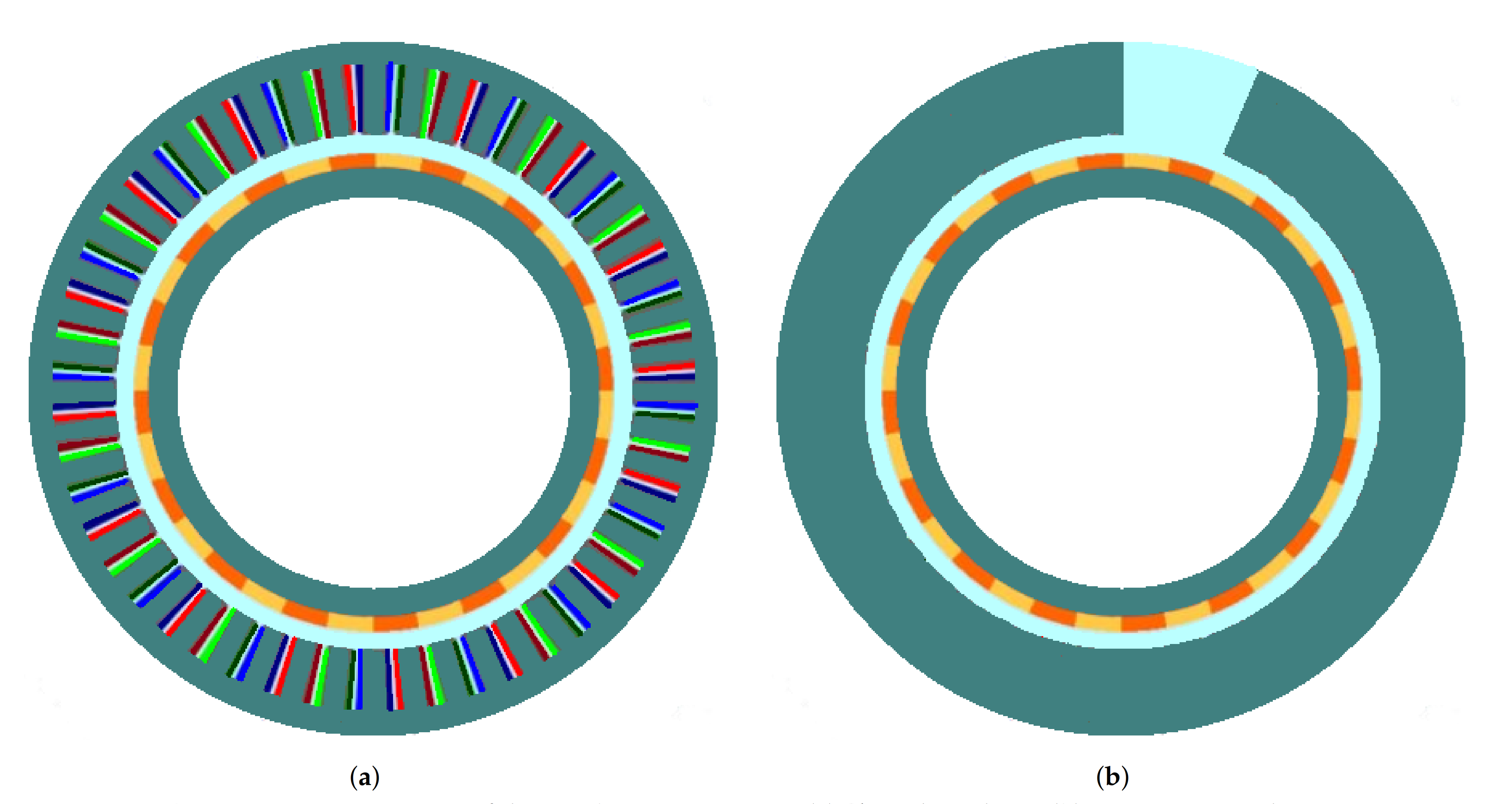
Figure 1.
Structures of permanent magnet synchronous machines with (a) stator and (b) rotor segmentations.
Figure 1.
Structures of permanent magnet synchronous machines with (a) stator and (b) rotor segmentations.
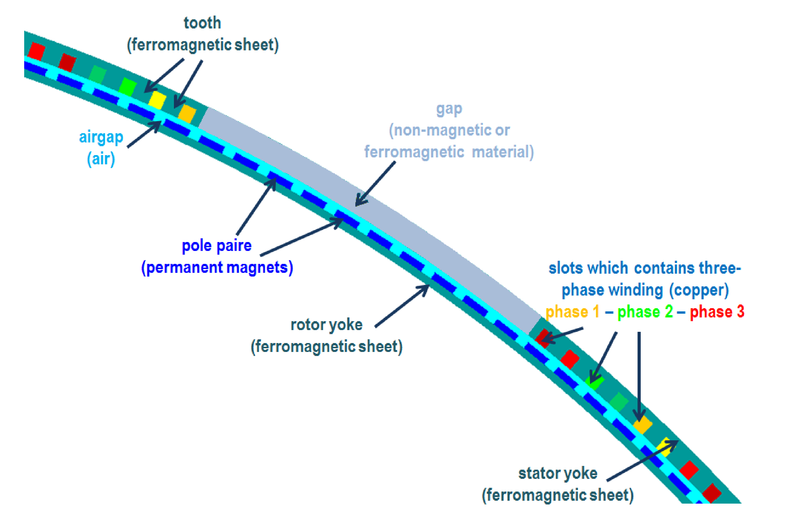
Figure 2.
Stator-segmented structure.
Figure 2.
Stator-segmented structure.
Figure 3.
Magnetic circuits of the studied machines: (a) non-segmented machine, (b) stator-segmented machine with amagnetic gaps, (c) rotor-segmented machine with amagnetic gaps.
Figure 3.
Magnetic circuits of the studied machines: (a) non-segmented machine, (b) stator-segmented machine with amagnetic gaps, (c) rotor-segmented machine with amagnetic gaps.
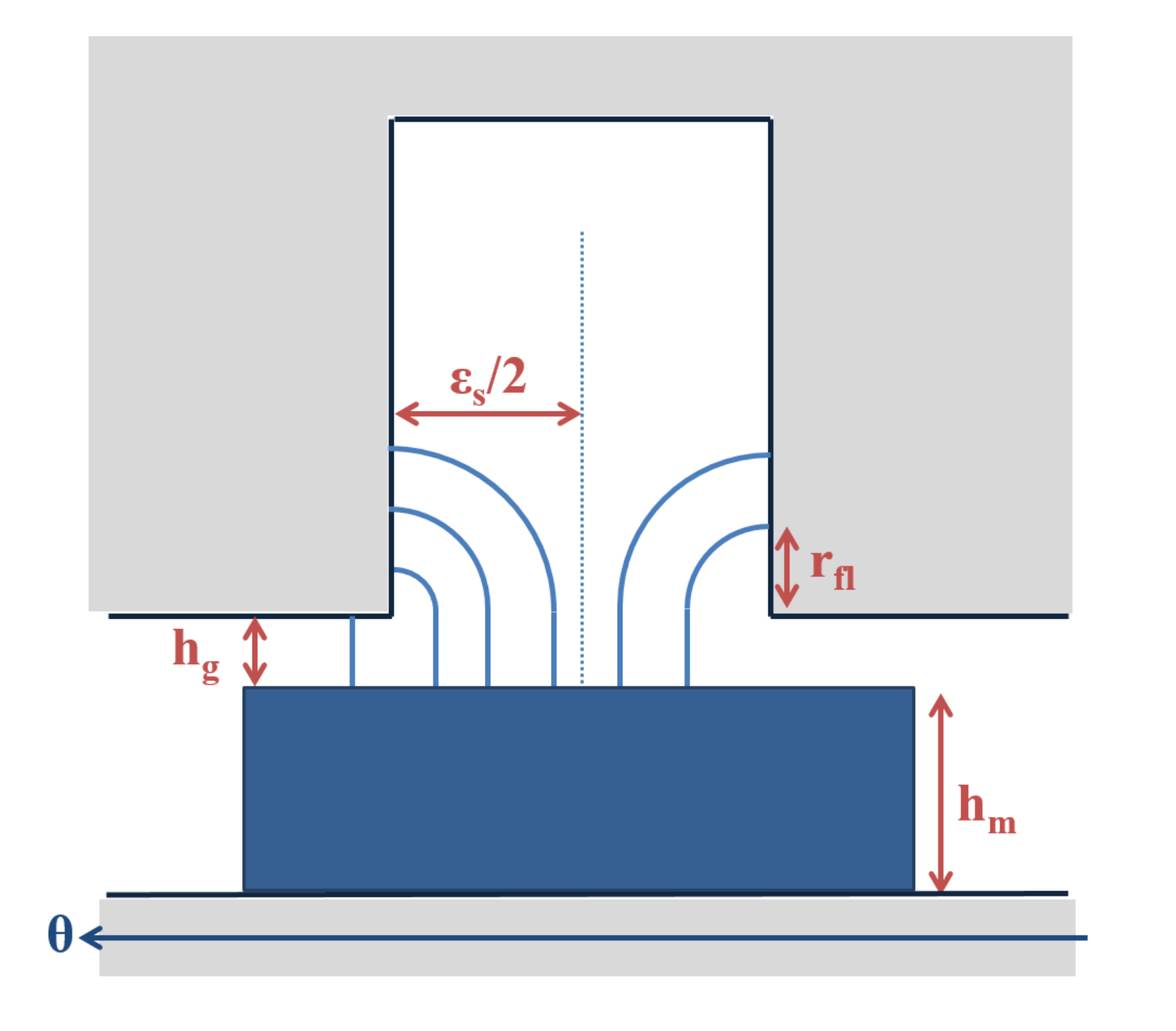
Figure 4.
Flux lines in a slot opening for a radial magnetization.
Figure 4.
Flux lines in a slot opening for a radial magnetization.
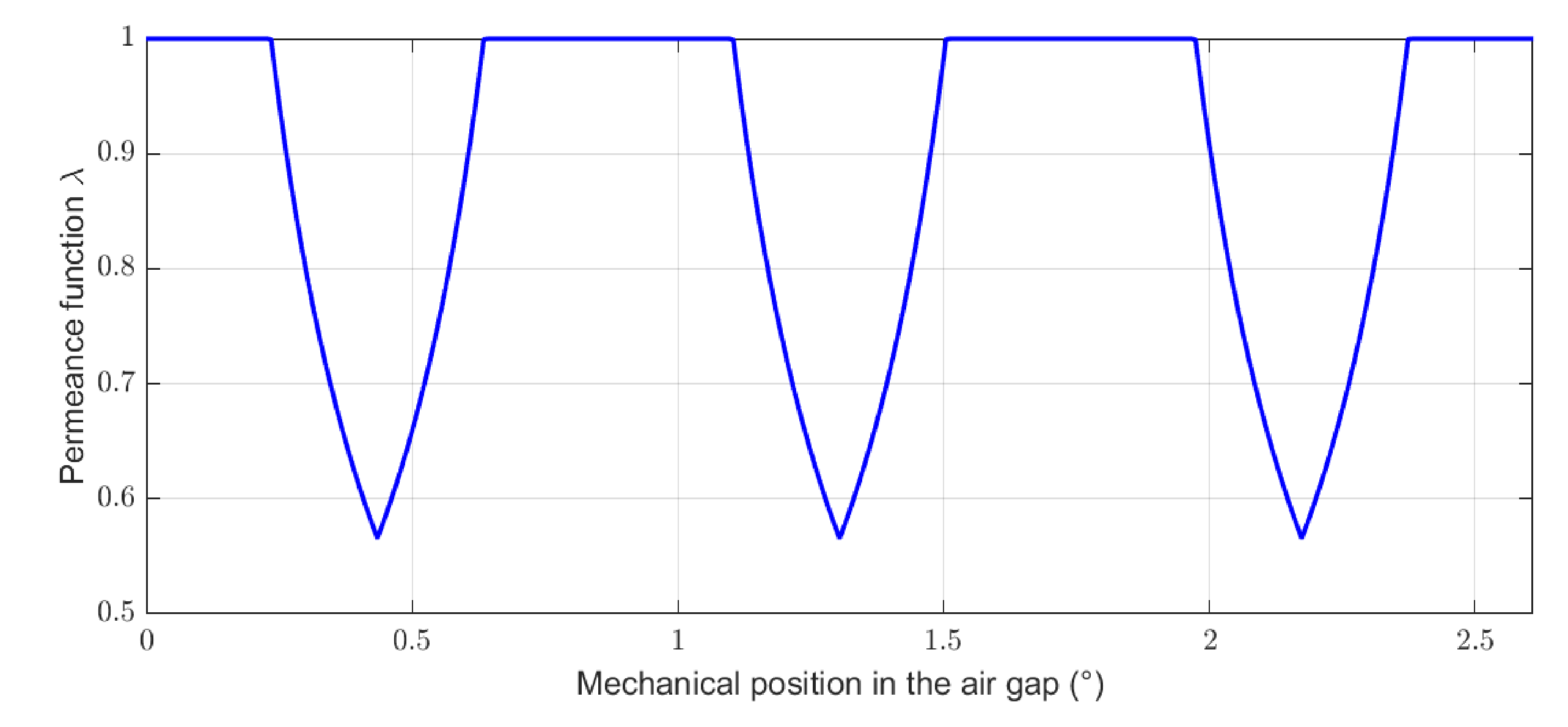
Figure 5.
Permeance function taking into account the slot openings for a non-segmented machine.
Figure 5.
Permeance function taking into account the slot openings for a non-segmented machine.
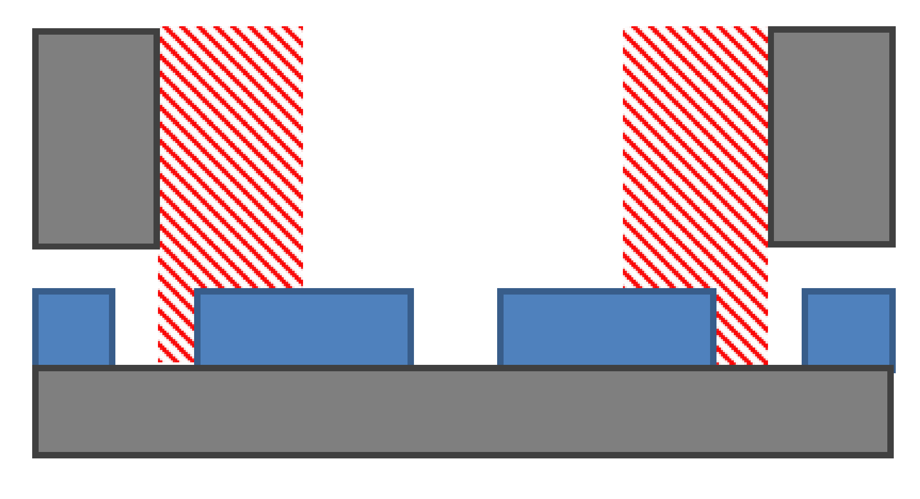
Figure 6.
Areas used for the calculation of the cogging torque.
Figure 6.
Areas used for the calculation of the cogging torque.
Figure 7.
Permeance function (relative value) for the machine under consideration with stator segmentation by an amagnetic material (336 slots, 140 pole pairs, 7 gaps, and 25% of gap).
Figure 7.
Permeance function (relative value) for the machine under consideration with stator segmentation by an amagnetic material (336 slots, 140 pole pairs, 7 gaps, and 25% of gap).
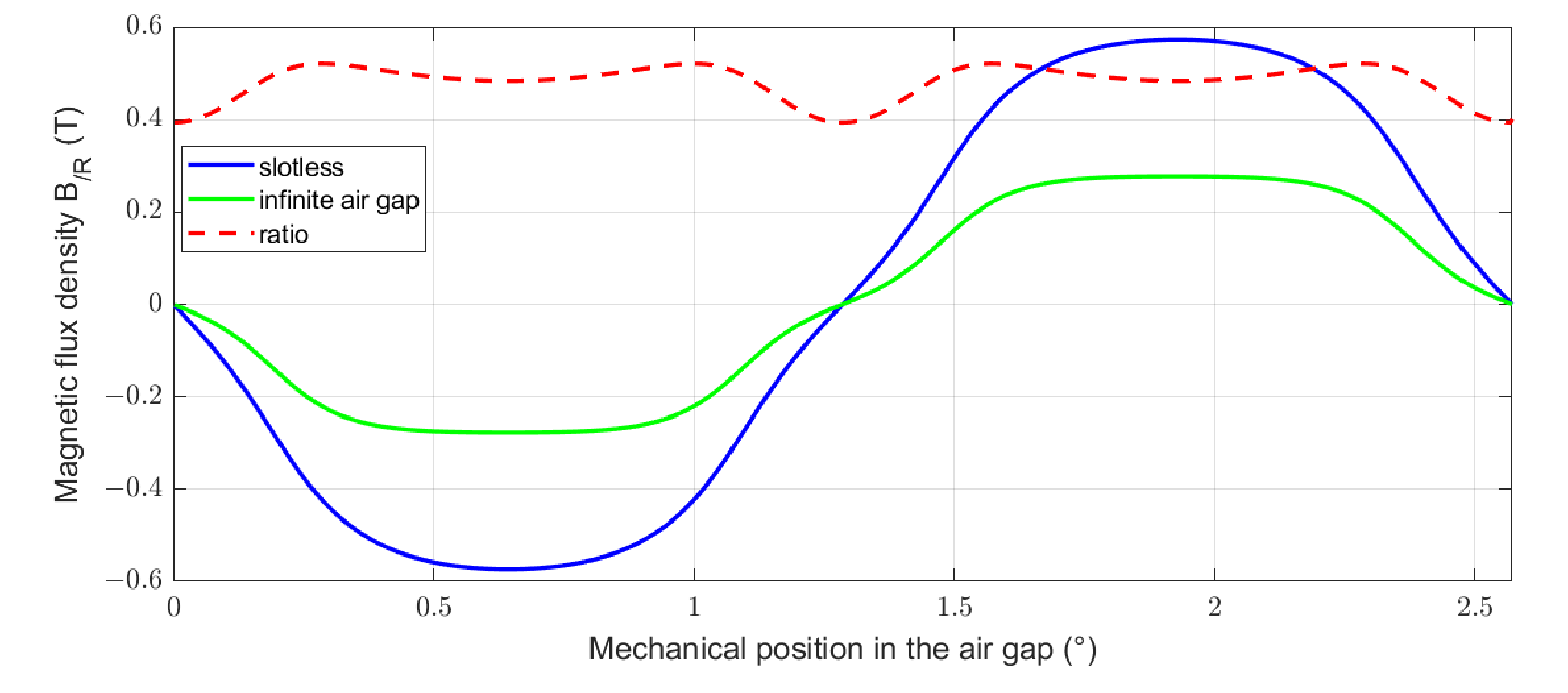
Figure 8.
Analytical evaluation of the ratio between the magnetic flux density of a machine with an infinite air gap and of a slotless machine.
Figure 8.
Analytical evaluation of the ratio between the magnetic flux density of a machine with an infinite air gap and of a slotless machine.
Figure 9.
Magnetic circuit of the two basics structures. (a) Slotted machine. (b) Mono-gap machine.
Figure 9.
Magnetic circuit of the two basics structures. (a) Slotted machine. (b) Mono-gap machine.
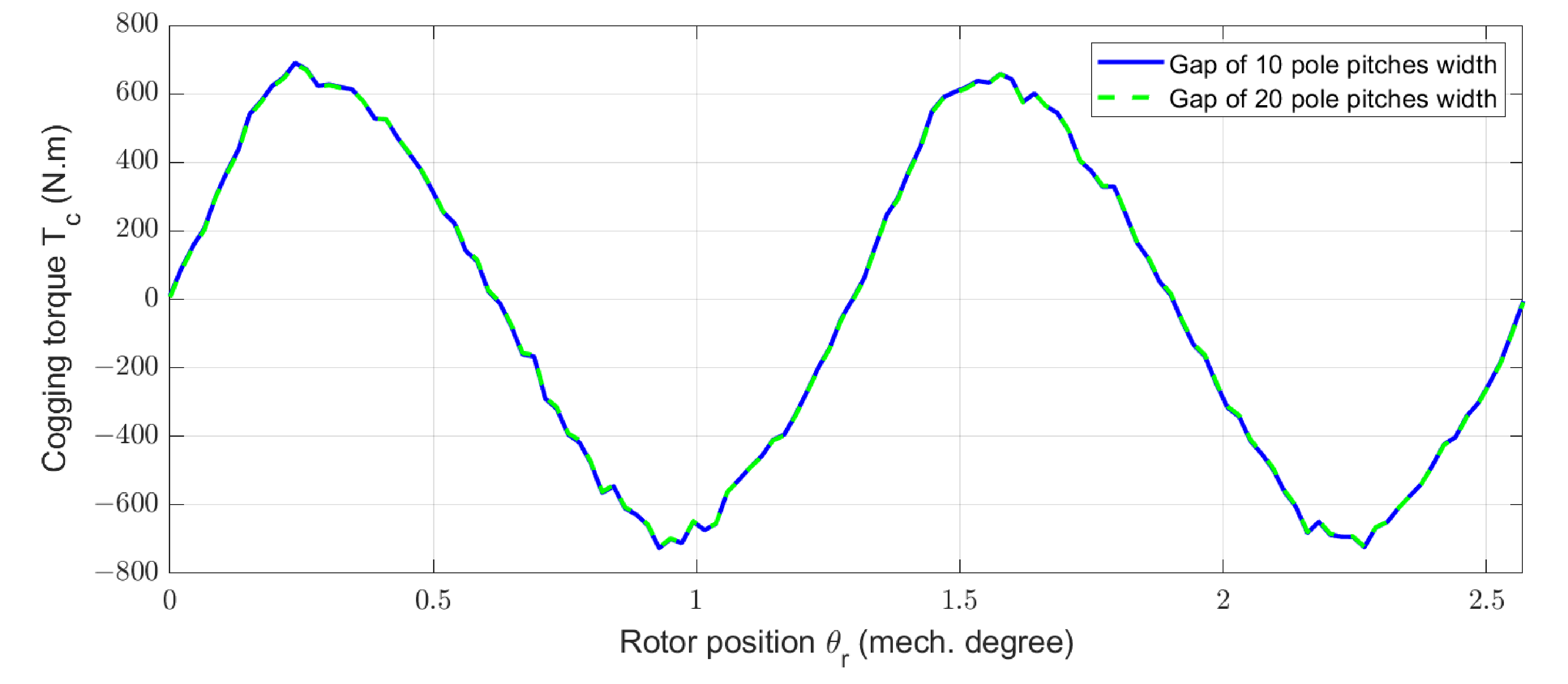
Figure 10.
Cogging torque for two mono-gap widths estimated by numerical method (FEM).
Figure 10.
Cogging torque for two mono-gap widths estimated by numerical method (FEM).
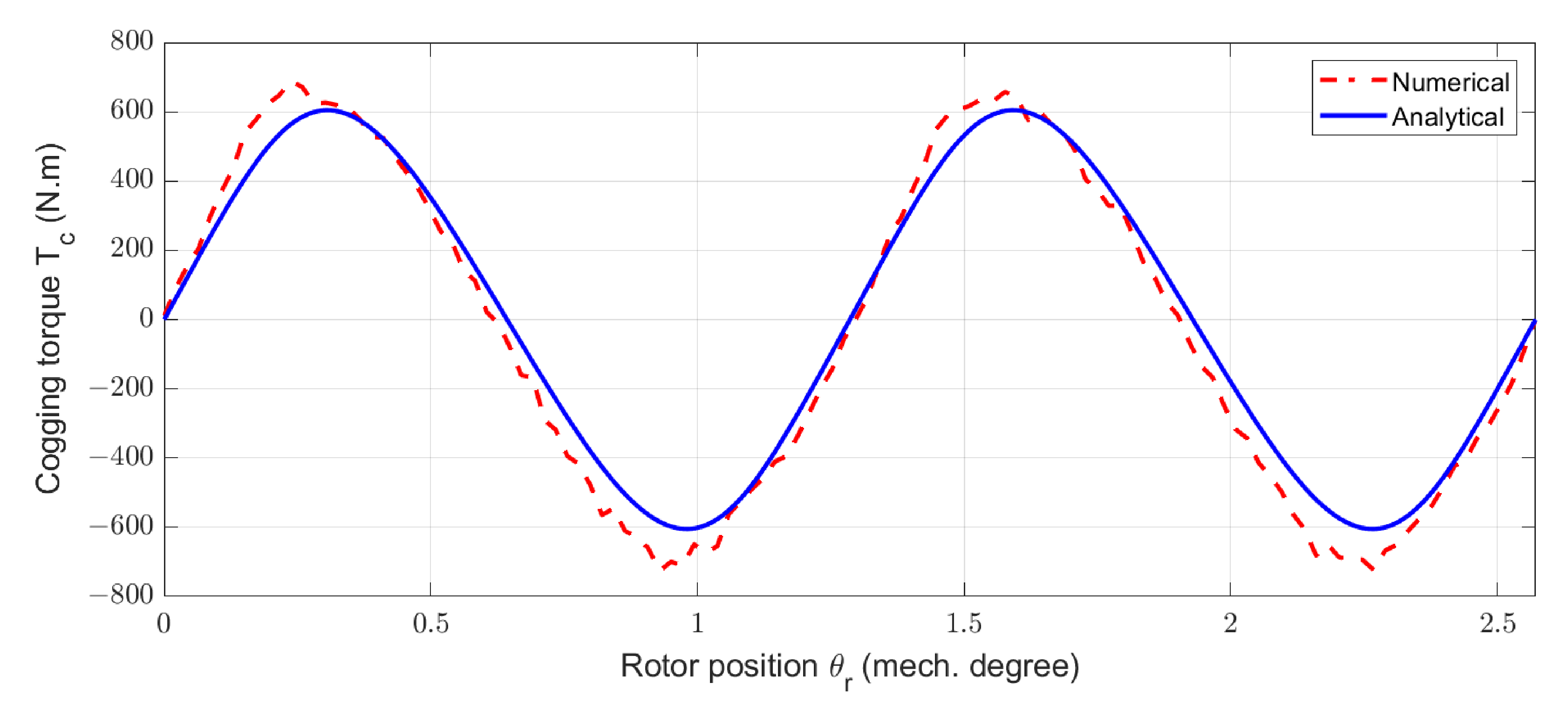
Figure 11.
Cogging torques obtained by numerical and analytical models for a machine with only one gap of ten-pole pitches.
Figure 11.
Cogging torques obtained by numerical and analytical models for a machine with only one gap of ten-pole pitches.
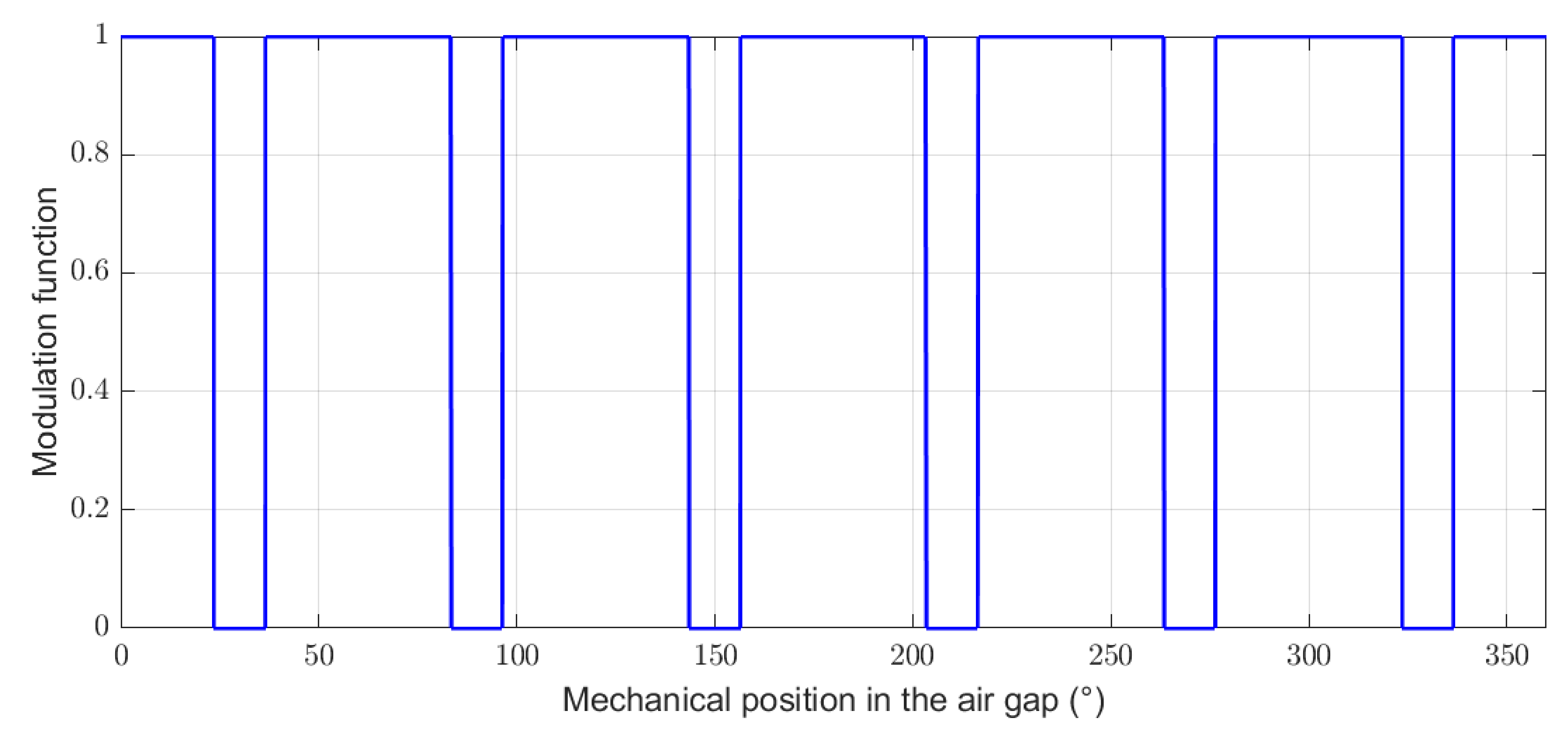
Figure 12.
Modulation function to take into account the parts without magnet for a structure with around 20% and gaps.
Figure 12.
Modulation function to take into account the parts without magnet for a structure with around 20% and gaps.
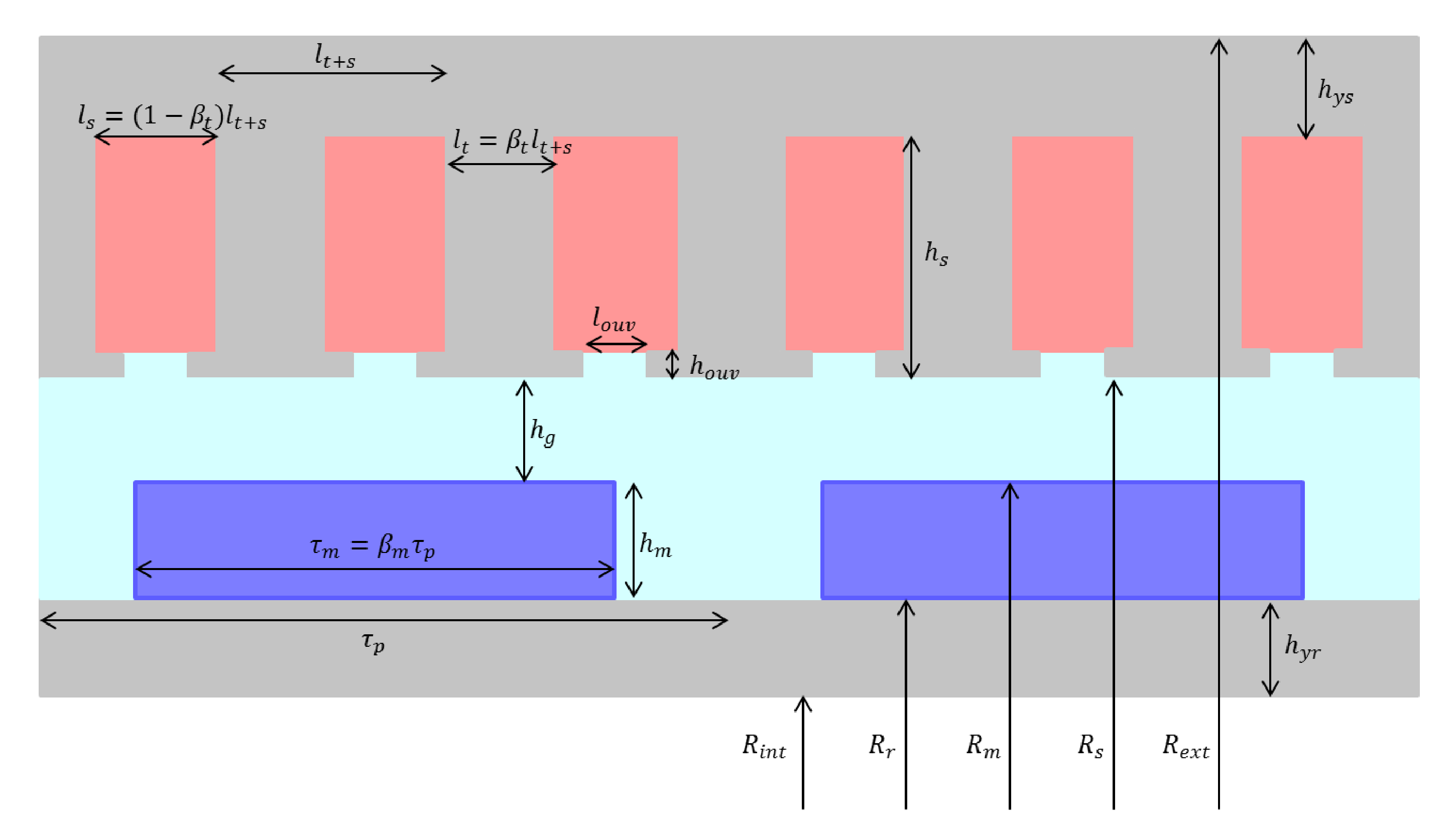
Figure 13.
Representation of the geometric parameters.
Figure 13.
Representation of the geometric parameters.
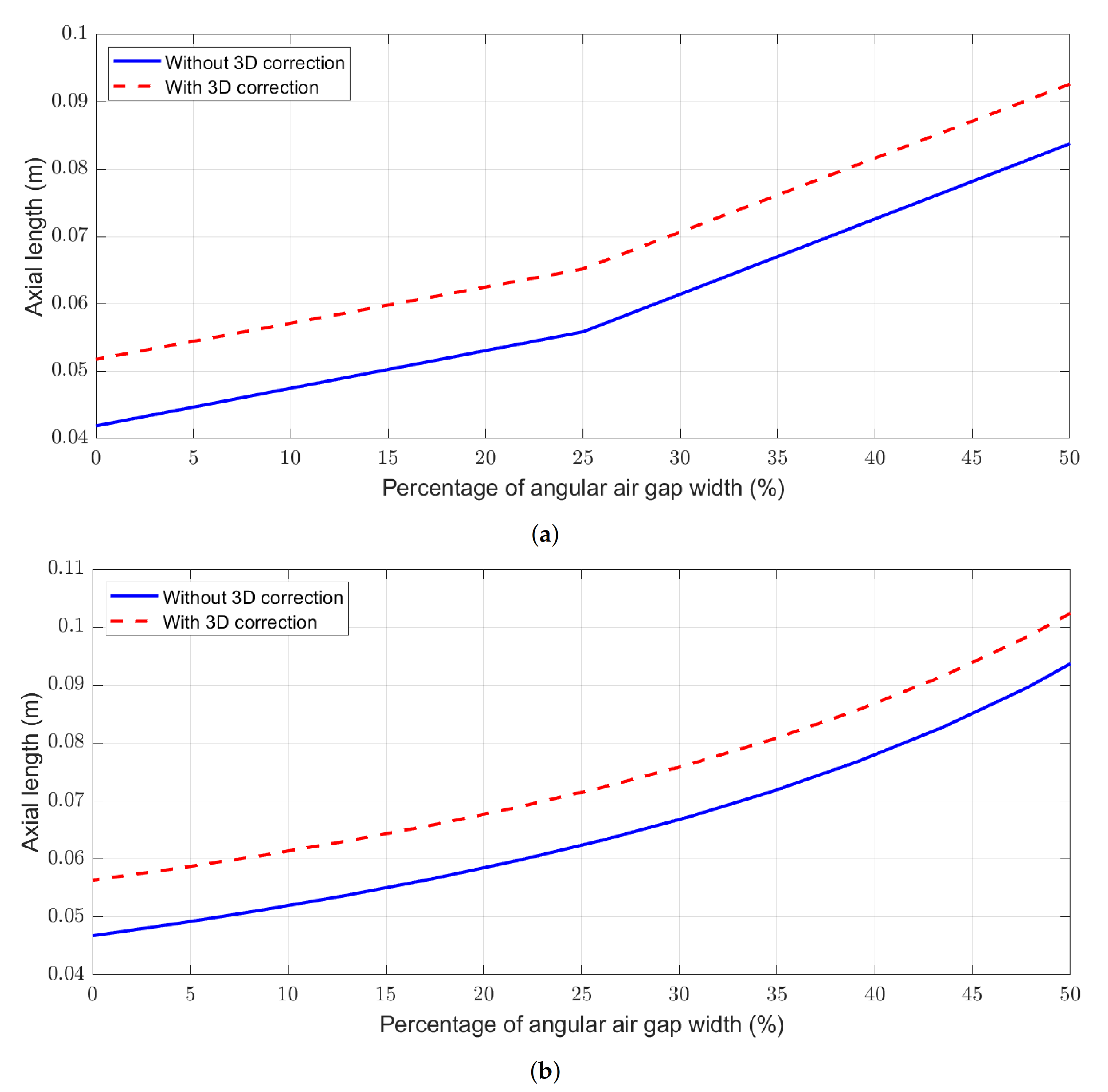
Figure 14.
Axial length depending on the proportion of segmentation, with and without considering the 3D correction, for the machines (a) with and (b) with .
Figure 14.
Axial length depending on the proportion of segmentation, with and without considering the 3D correction, for the machines (a) with and (b) with .
Figure 15.
Studied machines. (a) Non-segmented machine with = 2/5. (b) Stator-segmented machine with 25% of amagnetic gap. (c) Non-segmented machine with = 1/2. (d) Rotor-segmented machine with around 20% of amagnetic gap.
Figure 15.
Studied machines. (a) Non-segmented machine with = 2/5. (b) Stator-segmented machine with 25% of amagnetic gap. (c) Non-segmented machine with = 1/2. (d) Rotor-segmented machine with around 20% of amagnetic gap.
Figure 16.
Permeance function for the SS-machine with = 0.50. (a) = 7 gaps. (b) = 14 gaps.
Figure 16.
Permeance function for the SS-machine with = 0.50. (a) = 7 gaps. (b) = 14 gaps.
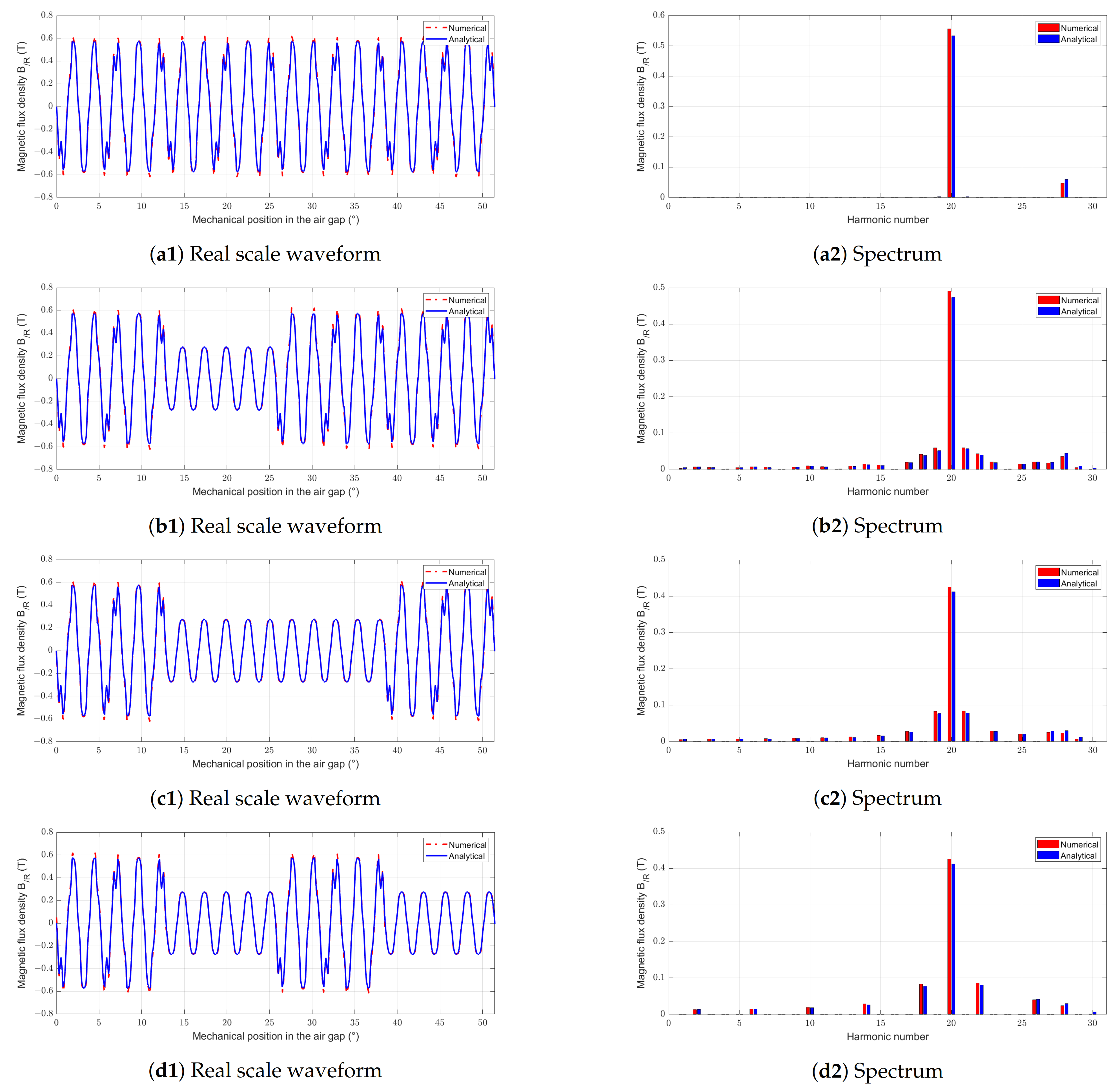
Figure 17.
Waveforms and spectral analysis of magnetic flux density for the SS-machine with different pgap and ngap (a1,a2) Reference machine. (b1,b2) SS-machine with pgap = 0.25 and ngap = 7 gaps. (c1,c2) SS-machine with pgap = 0.50 and ngap = 7 gaps. (d1,d2) SS-machine with pgap = 0.50 and ngap = 14 gaps.
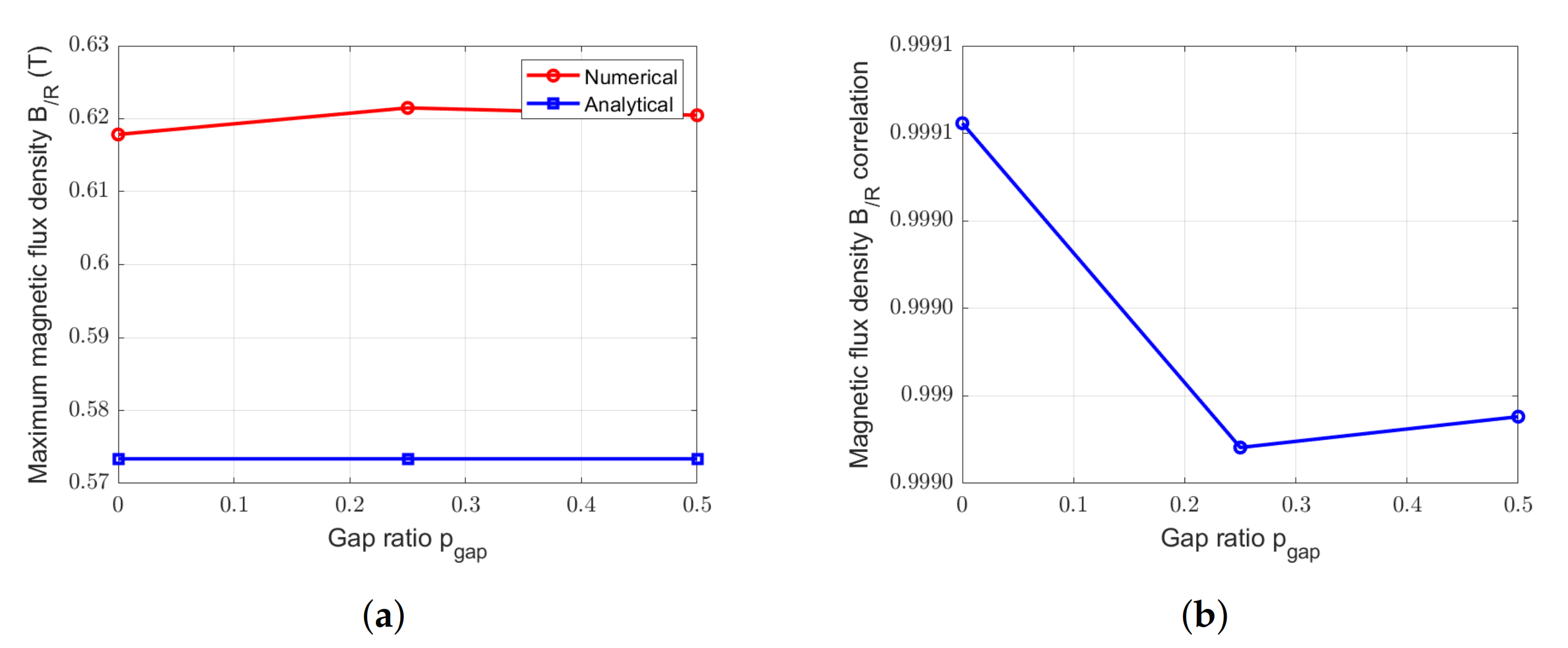
Figure 18.
Comparison between numerical and analytical calculation of magnetic flux densities due to PM for the SS-machine with = 7 gaps and with different . (a) Peak values. (b) Correlation.
Figure 18.
Comparison between numerical and analytical calculation of magnetic flux densities due to PM for the SS-machine with = 7 gaps and with different . (a) Peak values. (b) Correlation.
Figure 19.
Comparison between numerical and analytical calculation of magnetic flux densities due to PM for the SS-machine with = 0.50 and with different . (a) Peak values. (b) Correlation.
Figure 19.
Comparison between numerical and analytical calculation of magnetic flux densities due to PM for the SS-machine with = 0.50 and with different . (a) Peak values. (b) Correlation.
Figure 20.
Waveforms and spectral analysis of magnetic flux density for the RS-machine with different pgap and ngap = 6 gaps. (a1,a2) Reference machine. (b1,b2) RS-machine with pgap = 0.217. (c1,c2) RS-machine with pgap = 0.391.
Figure 20.
Waveforms and spectral analysis of magnetic flux density for the RS-machine with different pgap and ngap = 6 gaps. (a1,a2) Reference machine. (b1,b2) RS-machine with pgap = 0.217. (c1,c2) RS-machine with pgap = 0.391.
Figure 21.
Comparison between numerical and analytical calculation of magnetic flux densities due to PM for the RS-machine with = 6 gaps and with different . (a) Peak values. (b) Correlation.
Figure 21.
Comparison between numerical and analytical calculation of magnetic flux densities due to PM for the RS-machine with = 6 gaps and with different . (a) Peak values. (b) Correlation.
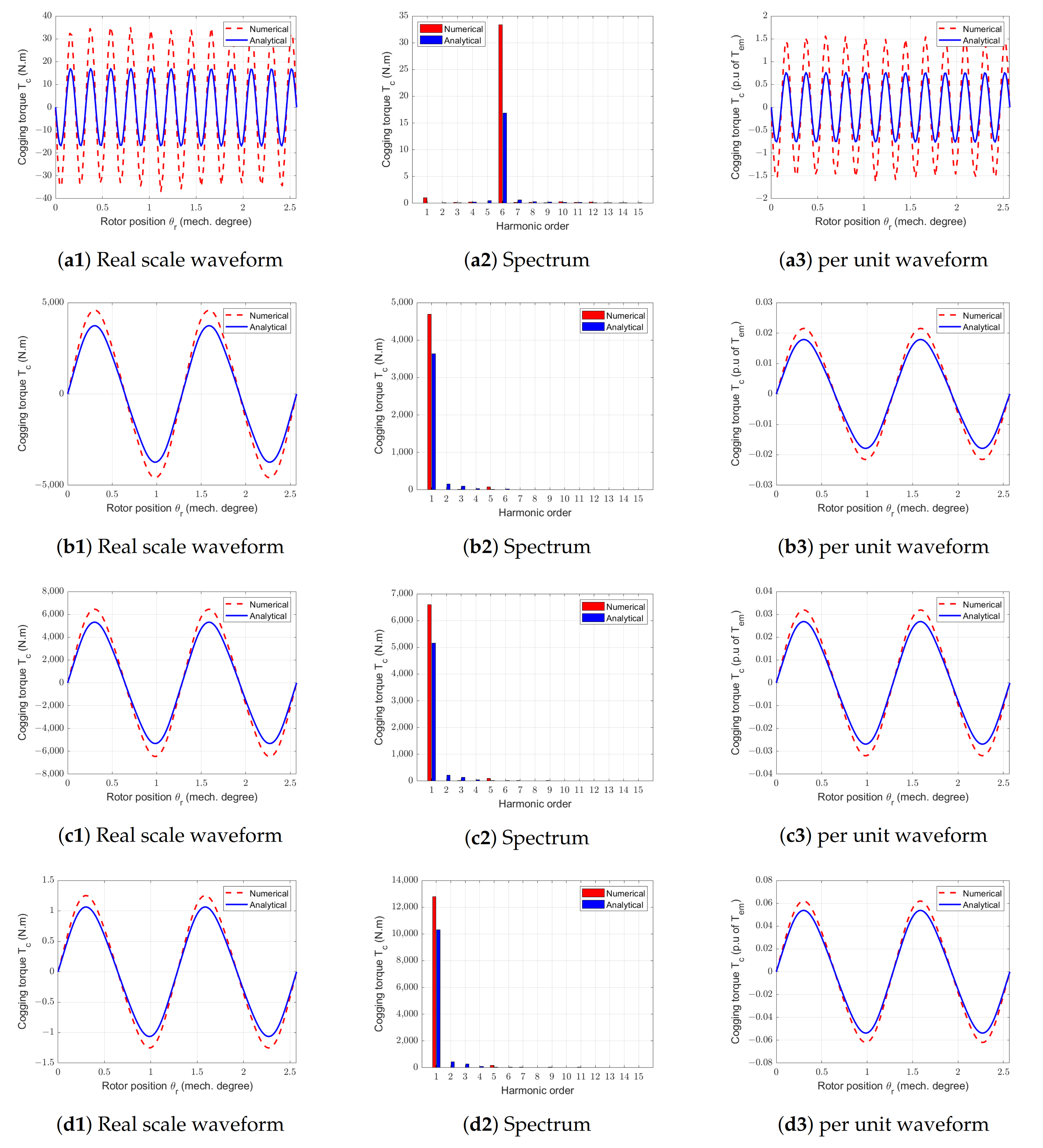
Figure 22.
Waveforms and spectral analysis of cogging torques for the SS-machine with different pgap and ngap. (a1–a3) Reference machine. (b1–b3) SS-machine with pgap = 0.25 and ngap = 7 gaps. (c1–c3) SS-machine with pgap = 0.50 and ngap = 7 gaps. (d1–d3) SS-machine with pgap = 0.50 and ngap = 14 gaps.
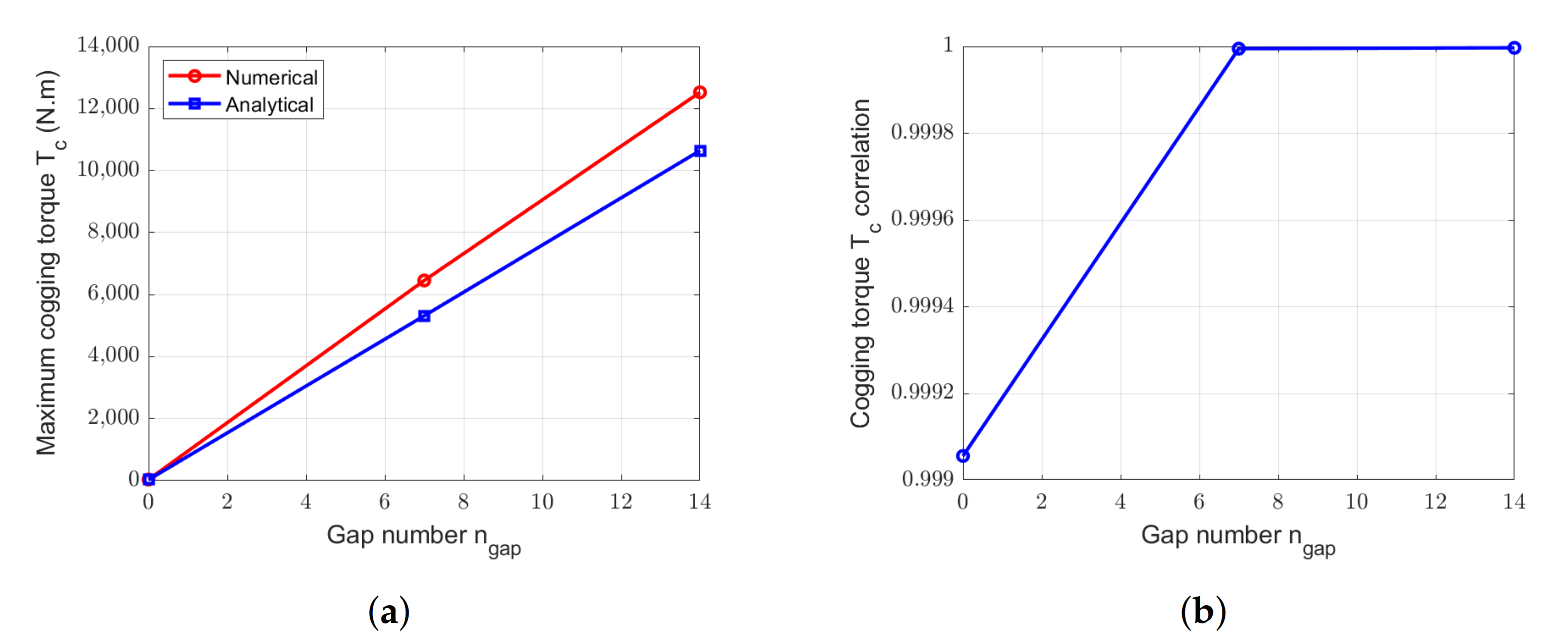
Figure 23.
Comparison between numerical and analytical calculation of cogging torque for the SS-machine with = 7 gaps and with different . (a) Peak values. (b) Correlation.
Figure 23.
Comparison between numerical and analytical calculation of cogging torque for the SS-machine with = 7 gaps and with different . (a) Peak values. (b) Correlation.
Figure 24.
Comparison between numerical and analytical calculation of cogging torque for the SS-machine with = 0.50 and with different . (a) Peak values. (b) Correlation.
Figure 24.
Comparison between numerical and analytical calculation of cogging torque for the SS-machine with = 0.50 and with different . (a) Peak values. (b) Correlation.
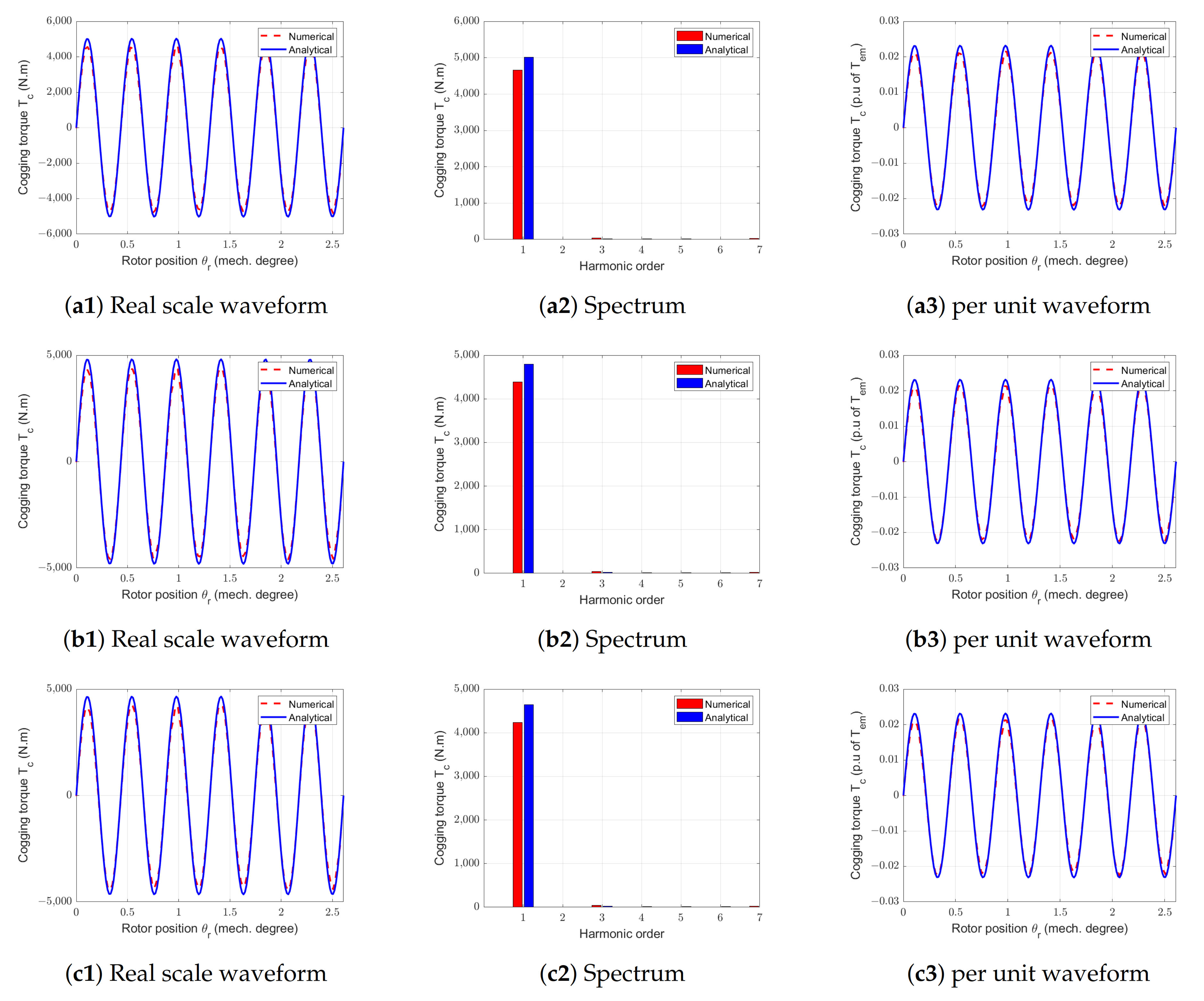
Figure 25.
Waveforms and spectral analysis of cogging tprques for the RS-machine with different pgap and ngap = 6 gaps. (a1–a3) Reference machine. (b1–b3) pgap = 0.217. (c1–c3) pgap = 0.391.
Figure 25.
Waveforms and spectral analysis of cogging tprques for the RS-machine with different pgap and ngap = 6 gaps. (a1–a3) Reference machine. (b1–b3) pgap = 0.217. (c1–c3) pgap = 0.391.
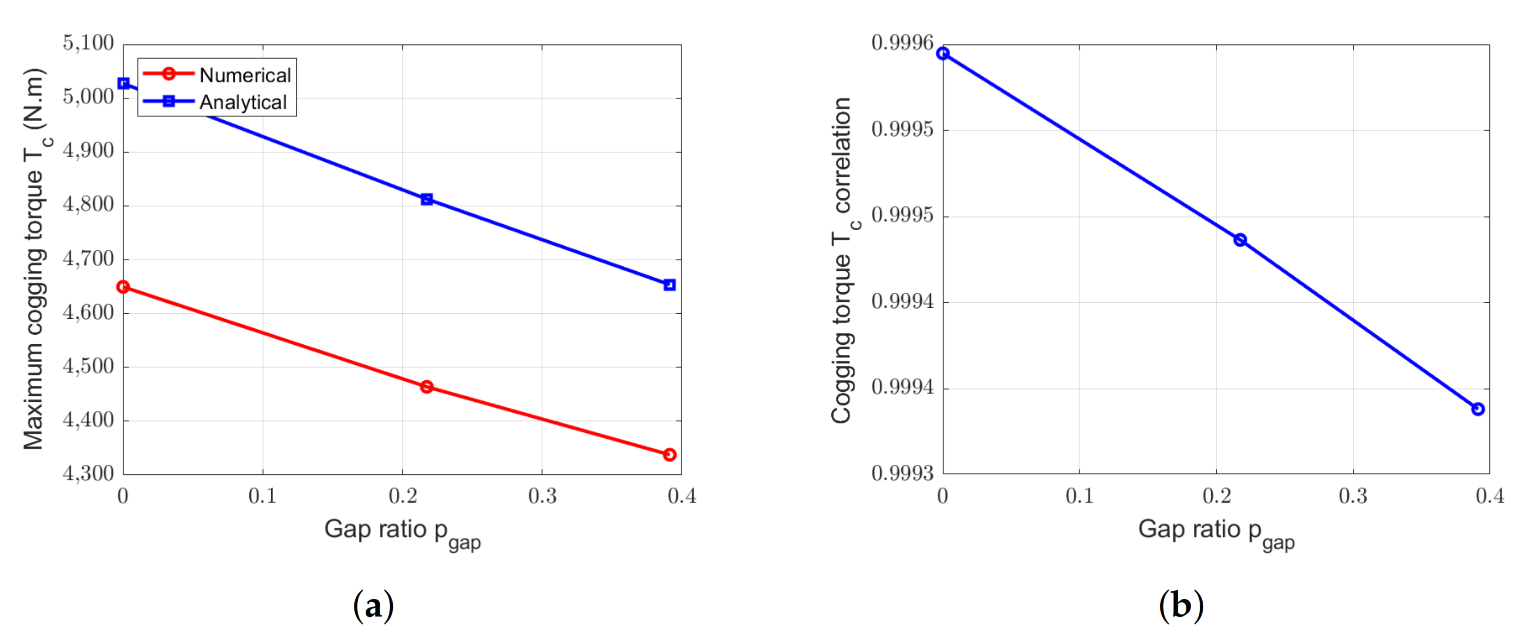
Figure 26.
Comparison between numerical and analytical calculation of cogging torque for the RS-machine with = 6 gaps and with different . (a) Peak values. (b) Correlation.
Figure 26.
Comparison between numerical and analytical calculation of cogging torque for the RS-machine with = 6 gaps and with different . (a) Peak values. (b) Correlation.
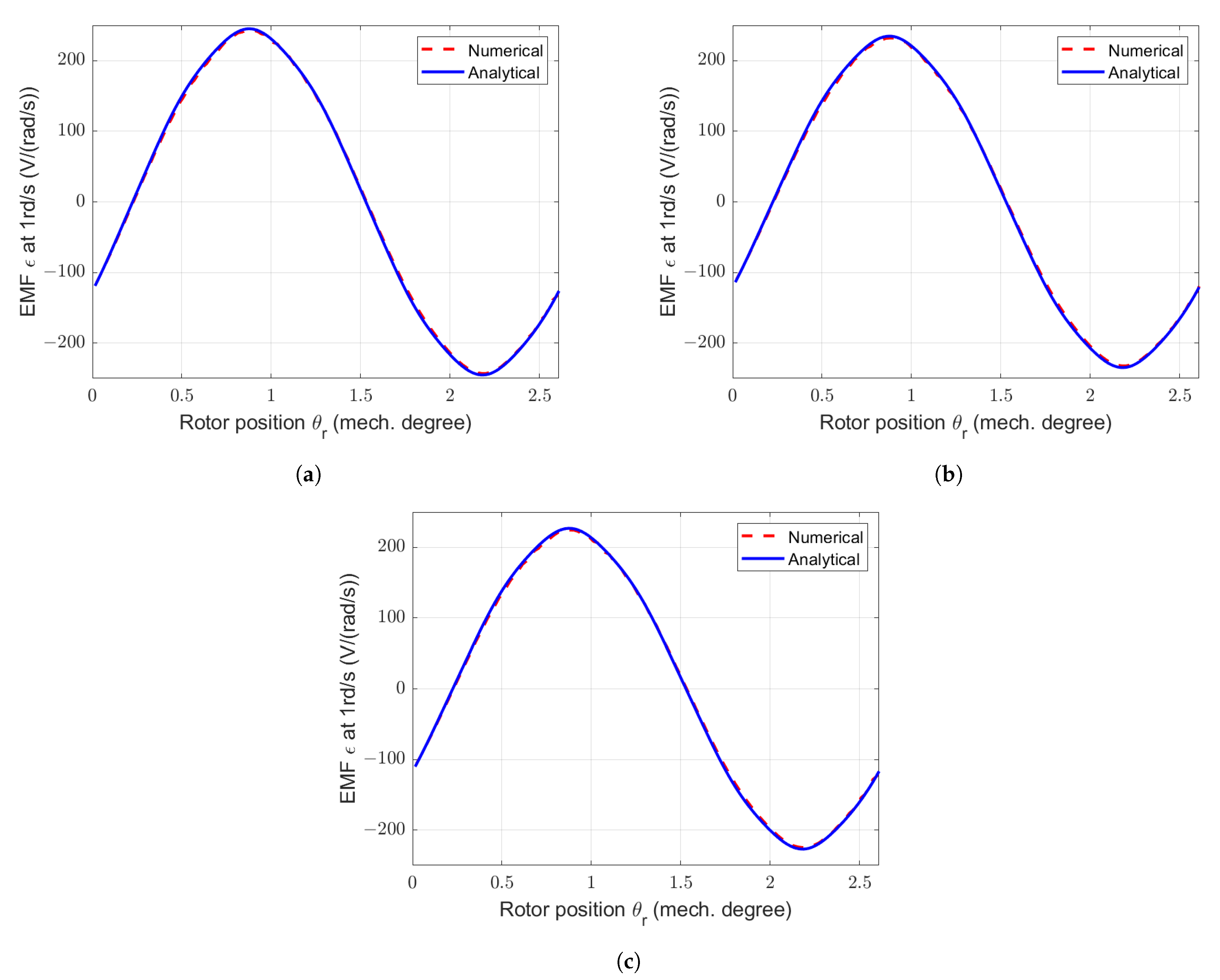
Figure 27.
Waveforms of electromotive forces in one phase (neutral phase) at 1rd/s for the SS-machine with different . (a) Reference machine. (b) SS-machine with and = 7 gaps. (c) SS-machine with and = 7 gaps.
Figure 27.
Waveforms of electromotive forces in one phase (neutral phase) at 1rd/s for the SS-machine with different . (a) Reference machine. (b) SS-machine with and = 7 gaps. (c) SS-machine with and = 7 gaps.
Figure 28.
Comparison between electromotive forces obtained by numerical and analytical methods in one phase at 1 rd/s for the SS-machine with = 7 gaps and with different . (a) Peak values. (b) Correlation.
Figure 28.
Comparison between electromotive forces obtained by numerical and analytical methods in one phase at 1 rd/s for the SS-machine with = 7 gaps and with different . (a) Peak values. (b) Correlation.
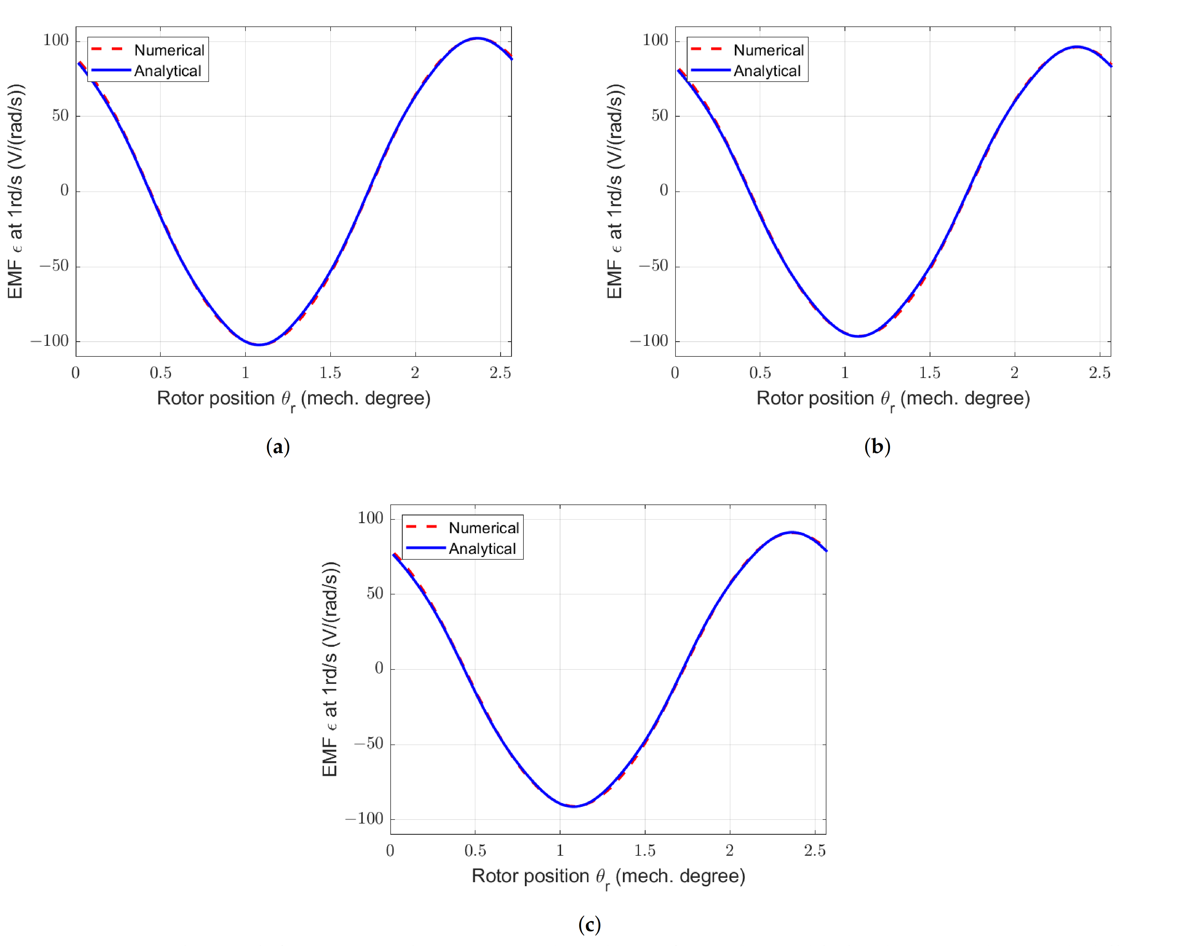
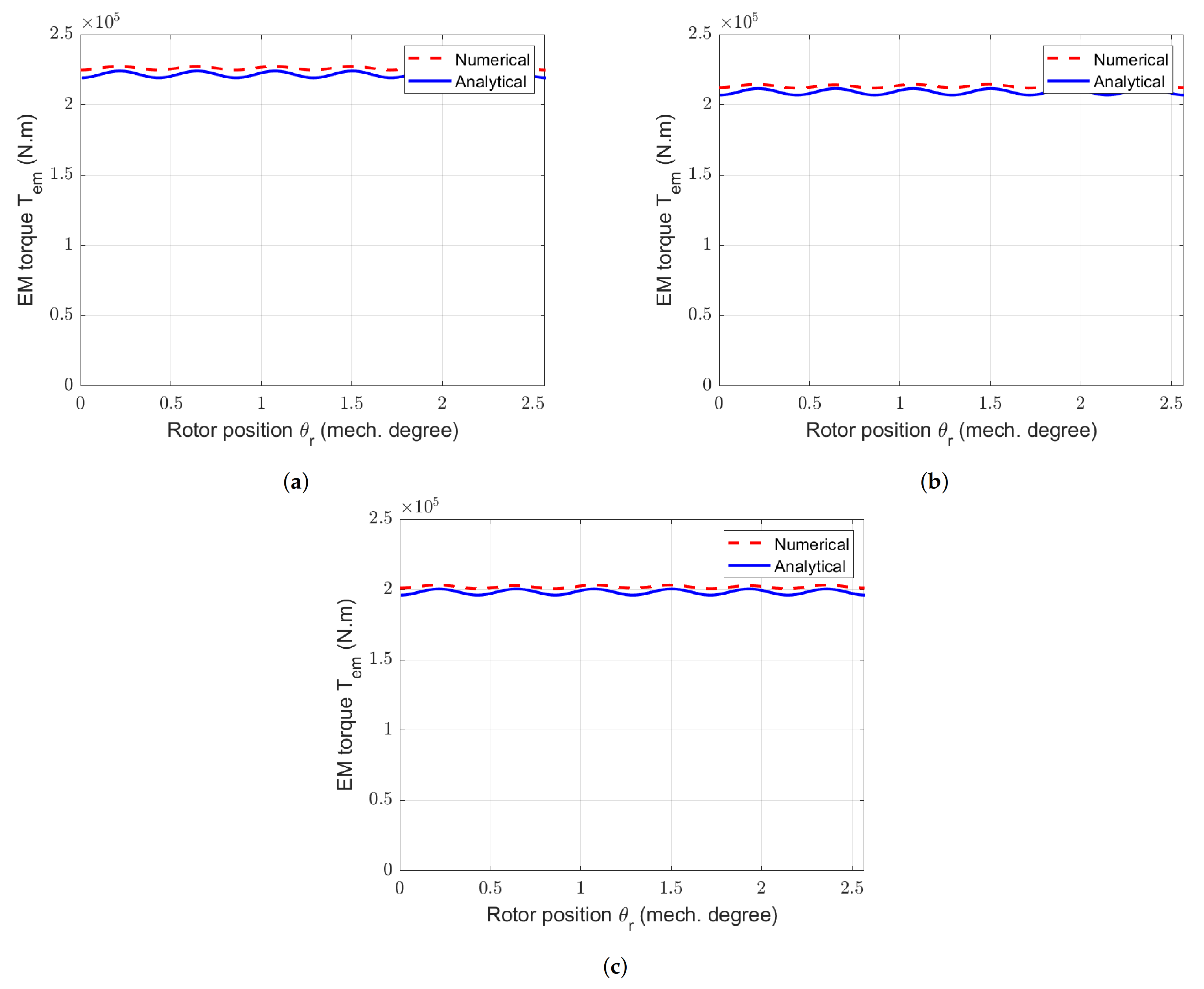
Figure 29.
Calculated waveforms of electromotive forces at 1 rd/s for the RS-machine with different . (a) Reference machine. (b) RS-machine with and = 7 gaps. (c) RS-machine with and = 6 gaps.
Figure 29.
Calculated waveforms of electromotive forces at 1 rd/s for the RS-machine with different . (a) Reference machine. (b) RS-machine with and = 7 gaps. (c) RS-machine with and = 6 gaps.
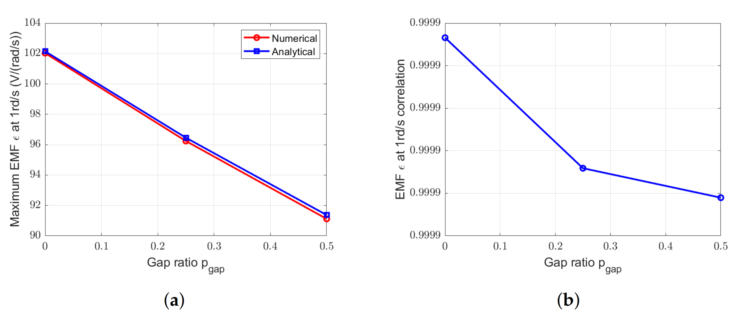
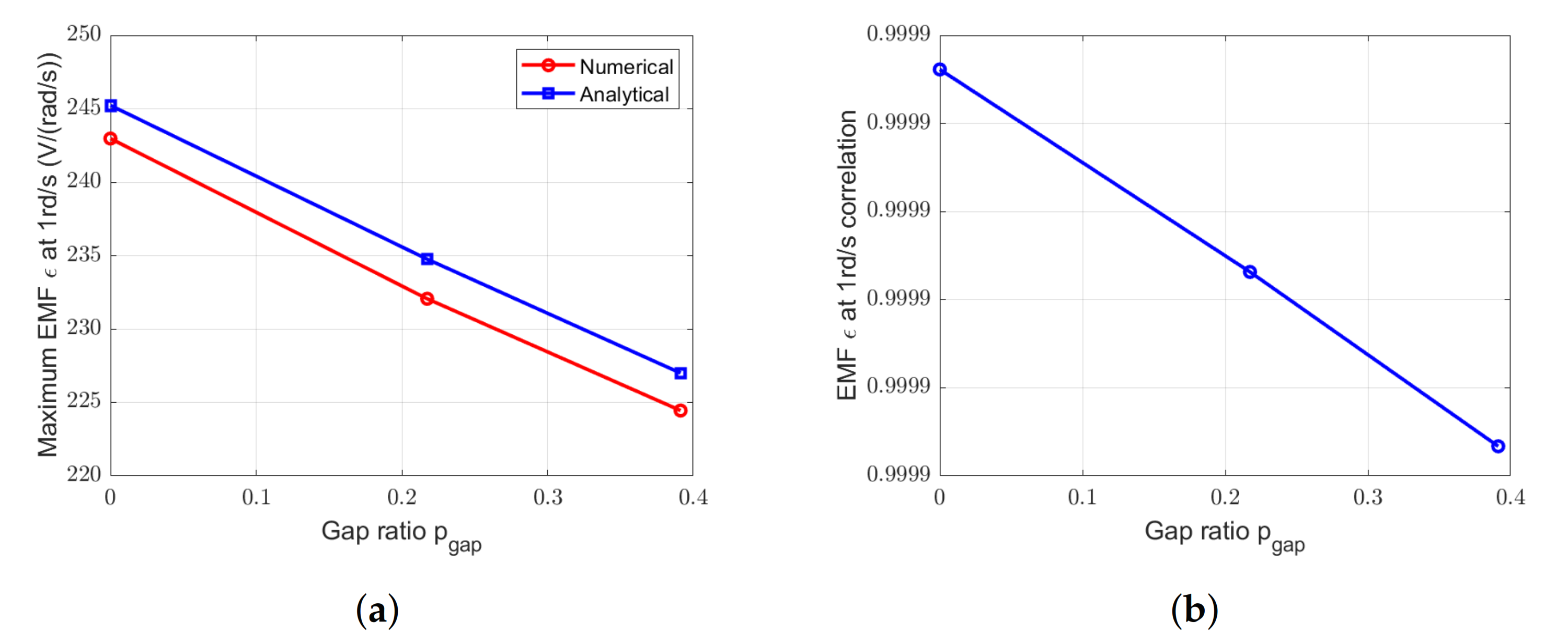
Figure 30.
Comparison between EMF obtained by numerical and analytical methods at 1 rd/s for the RS-machine with = 6 gaps and with different . (a) Peak values. (b) Correlation.
Figure 30.
Comparison between EMF obtained by numerical and analytical methods at 1 rd/s for the RS-machine with = 6 gaps and with different . (a) Peak values. (b) Correlation.
Figure 31.
Waveforms of EM torques for the SS-machine with different . (a) Reference machine. (b) SS-machine with and = 7 gaps. (c) SS-machine with and = 7 gaps.
Figure 31.
Waveforms of EM torques for the SS-machine with different . (a) Reference machine. (b) SS-machine with and = 7 gaps. (c) SS-machine with and = 7 gaps.
Figure 32.
Comparison between EM torques obtained by numerical and analytical methods for the SS-machine with = 7 gaps and with different . (a) Amplitude of the ripples. (b) Correlation.
Figure 32.
Comparison between EM torques obtained by numerical and analytical methods for the SS-machine with = 7 gaps and with different . (a) Amplitude of the ripples. (b) Correlation.
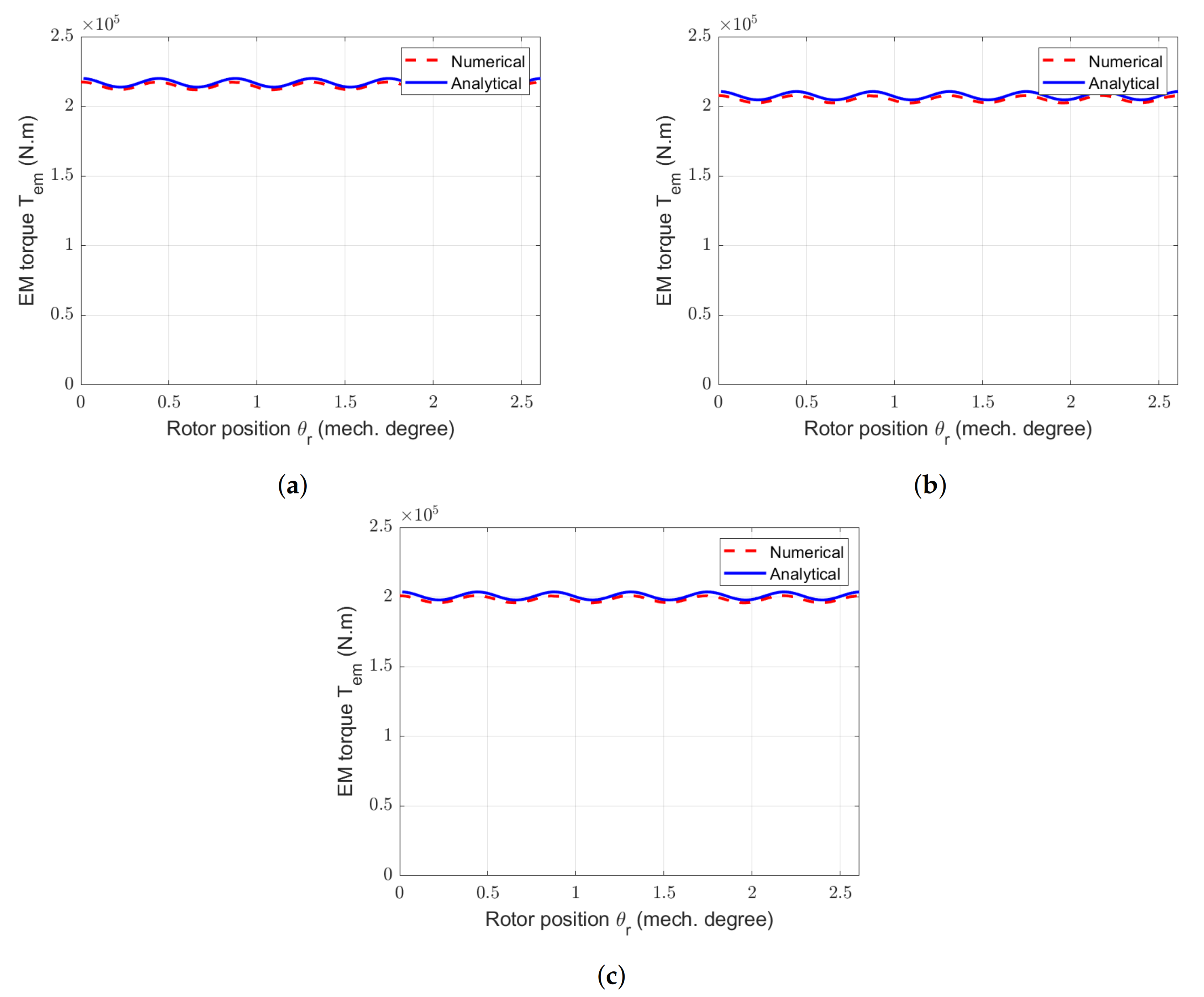
Figure 33.
Waveforms of EM torques for the RS-machine with different . (a) Reference machine. (b) RS-machine with and = 7 gaps. (c) RS-machine with and = 6 gaps.
Figure 33.
Waveforms of EM torques for the RS-machine with different . (a) Reference machine. (b) RS-machine with and = 7 gaps. (c) RS-machine with and = 6 gaps.
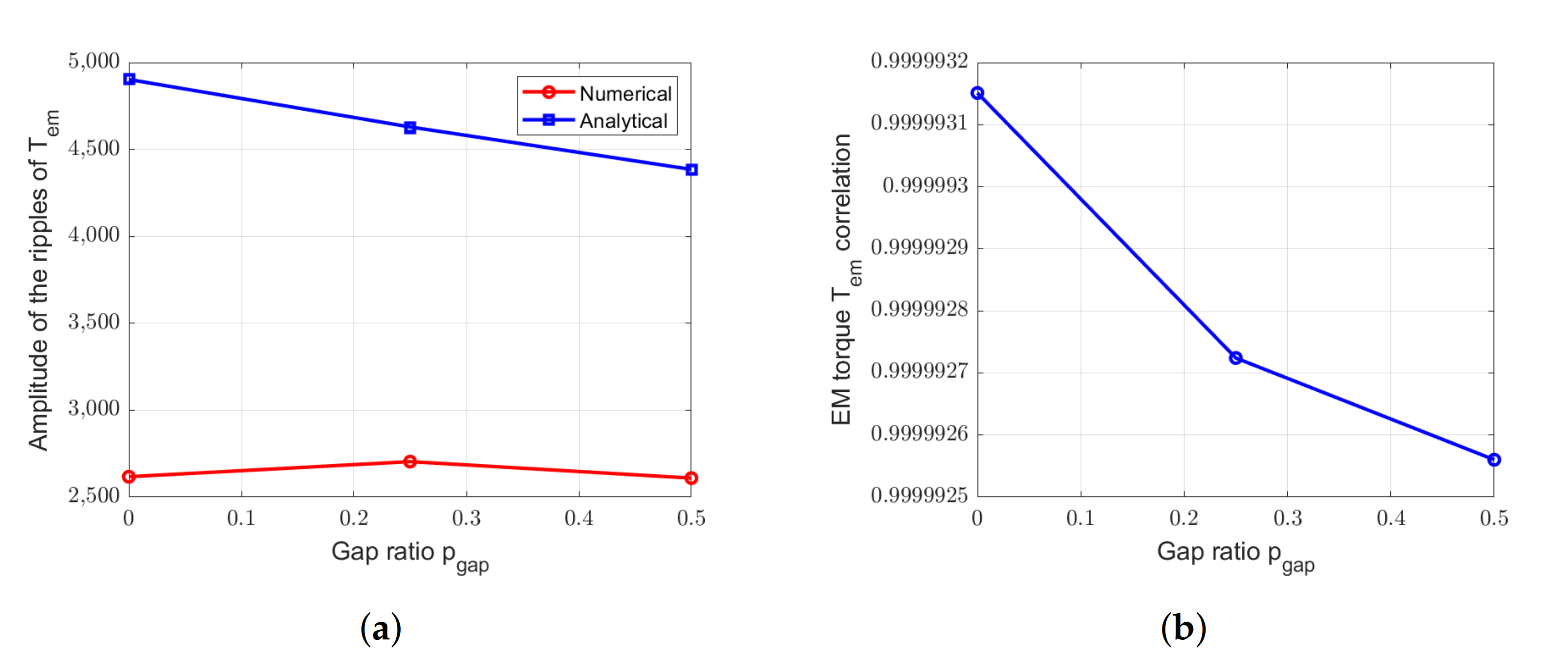
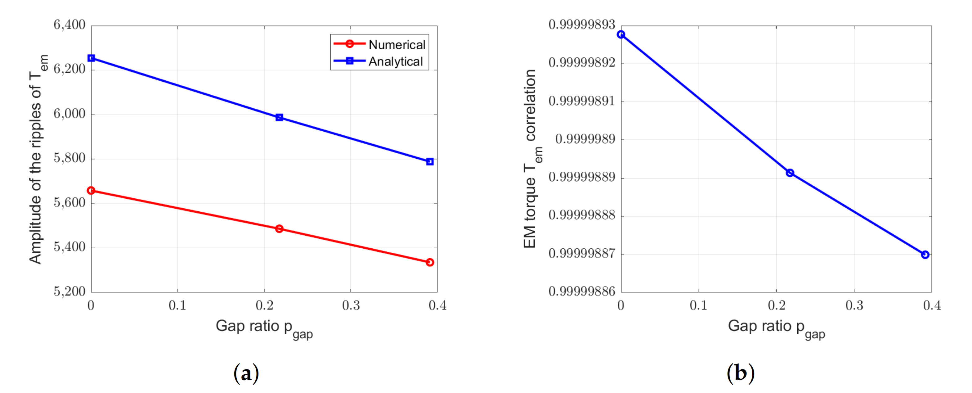
Figure 34.
Comparison between EM torques obtained by numerical and analytical methods for the RS-machine with =6 and with different . (a) Amplitude of the ripples. (b) Correlation.
Figure 34.
Comparison between EM torques obtained by numerical and analytical methods for the RS-machine with =6 and with different . (a) Amplitude of the ripples. (b) Correlation.
Table 1.
Main parameters of Rim-Driven machine (derived from [
7]).
Table 1.
Main parameters of Rim-Driven machine (derived from [
7]).
| Power P (kW) | 300 |
| Turbine speed N (rpm) | 15 |
| Air gap length (m) | 0.02 |
| Linear electric loading (kA×m) | 60 |
| Current density J (A×mm) | 4 |
| Magnet width () to pole pitch () ratio | 0.7 |
| Stator internal diameter D (m) | 11.151 |
| Magnet remanence (T) | 1.2 |
| Magnet relative permeability | 1.05 |
Table 2.
Main geometric parameters of reference machine designed to the rotor segmentation.
Table 2.
Main geometric parameters of reference machine designed to the rotor segmentation.
| Number of slots per pole and per phase | 1/2 |
| 1st harmonic winding coefficient | 0.866 [14] |
| Pole pair angular width (rad) | 2/138 |
| Magnet height (m) | 0.0208 |
| Slot depth (m) | 0.0434 |
| Tooth to slot pitch ratio | 0.54 |
| Stator and rotor yoke height hy (m) | 0.0236 |
| Iron axial length Lz0 (m) | 0.0564 |
Table 3.
Main geometric parameters of reference machine designed to the stator segmentation.
Table 3.
Main geometric parameters of reference machine designed to the stator segmentation.
| Number of slots per pole and per phase | 2/5 |
| 1st harmonic winding coefficient | 0.966 [14] |
| Pole pair angular width (rad) | 2/140 |
| Magnet height (m) | 0.0210 |
| Slot depth (m) | 0.0472 |
| Tooth to slot pitch ratio | 0.58 |
| Stator and rotor yoke height (m) | 0.0248 |
| Iron axial length (m) | 0.0518 |
Table 4.
Test case topology for the parametric variations.
Table 4.
Test case topology for the parametric variations.
| p | Segmented Part | | |
|---|
| 336 | 140 | none | 0 | 0 |
| 336 | 140 | stator | 0.25 | 7 |
| 336 | 140 | stator | 0.50 | 7 |
| 336 | 140 | stator | 0.50 | 14 |
| 414 | 138 | none | 0 | 0 |
| 414 | 138 | rotor | 0.217 | 6 |
| 414 | 138 | rotor | 0.391 | 6 |
Table 5.
Evolution of the mean electromagnetic torques for the SS-machine with = 7 gaps.
Table 5.
Evolution of the mean electromagnetic torques for the SS-machine with = 7 gaps.
| Gap Proportion | 0% | 25% | 50% |
|---|
| Numerical | 226 | 213 | 213 |
| Analytical | 222 | 209 | 209 |
| Ratio (%) | 98.2 | 98.1 | 98.1 |
Table 6.
Evolution of the mean electromagnetic torques for the RS-machine with = 6 gaps.
Table 6.
Evolution of the mean electromagnetic torques for the RS-machine with = 6 gaps.
| Gap Proportion | 0% | ~20% | ~40% |
|---|
| Numerical | 215 | 205 | 198 |
| Analytical | 217 | 208 | 201 |
| Ratio (%) | 99.1 | 98.6 | 98.5 |
Table 7.
Ratio between analytical and numerical value calculated for the studied EM quantities.
Table 7.
Ratio between analytical and numerical value calculated for the studied EM quantities.
| p | Segmented Part | | | Maximum | Maximum | Maximum EMF |
|---|
| 336 | 140 | none | 0 | 0 | 0.93 | 0.47 | 1.00 |
| 336 | 140 | stator | 0.25 | 7 | 0.92 | 0.92 | 1.00 |
| 336 | 140 | stator | 0.50 | 7 | 0.92 | 0.93 | 1.00 |
| 336 | 140 | stator | 0.50 | 14 | 0.93 | 0.96 | 1.01 |
| 414 | 138 | none | 0 | 0 | 0.93 | 0.92 | 1.0 |
| 414 | 138 | rotor | 0.217 | 6 | 0.91 | 0.93 | 1.01 |
| 414 | 138 | rotor | 0.391 | 6 | 0.91 | 0.93 | 1.01 |


