Article

Analytical Models for Fast and Accurate Calculation of Electromagnetic Performances of Segmented Permanent Magnet Synchronous Machines with Large Angular Gaps

by
Eulalie Fleurot
,
Franck Scuiller
and
Jean-Frédéric Charpentier
*
Research Institute of the French Naval Academy (IRENav), CC 600, 29240 Brest, France
*
Author to whom correspondence should be addressed.
Appl. Sci. 2021, 11(1), 459; https://doi.org/10.3390/app11010459
Submission received: 26 November 2020 / Revised: 28 December 2020 / Accepted: 28 December 2020 / Published: 5 January 2021

Abstract

:
In this paper original analytical models to determine the electromagnetic performances of segmented permanent magnet synchronous machines (with removed active parts in the stator or the rotor) are presented. These models are adapted to PMSM with large air gap width, large diameter, a high number of poles and large angular gaps. This method based on analytical approach is validated by comparizon with a 2D Finite Element calculation (Altair FluxTM 2D) for the specifications of a large diameter, low speed tidal high power current turbine generator. The presented method allows fast and accurate evaluation of the performances of this kind of particular machine and can be used in a systematic design process.

1. Introduction

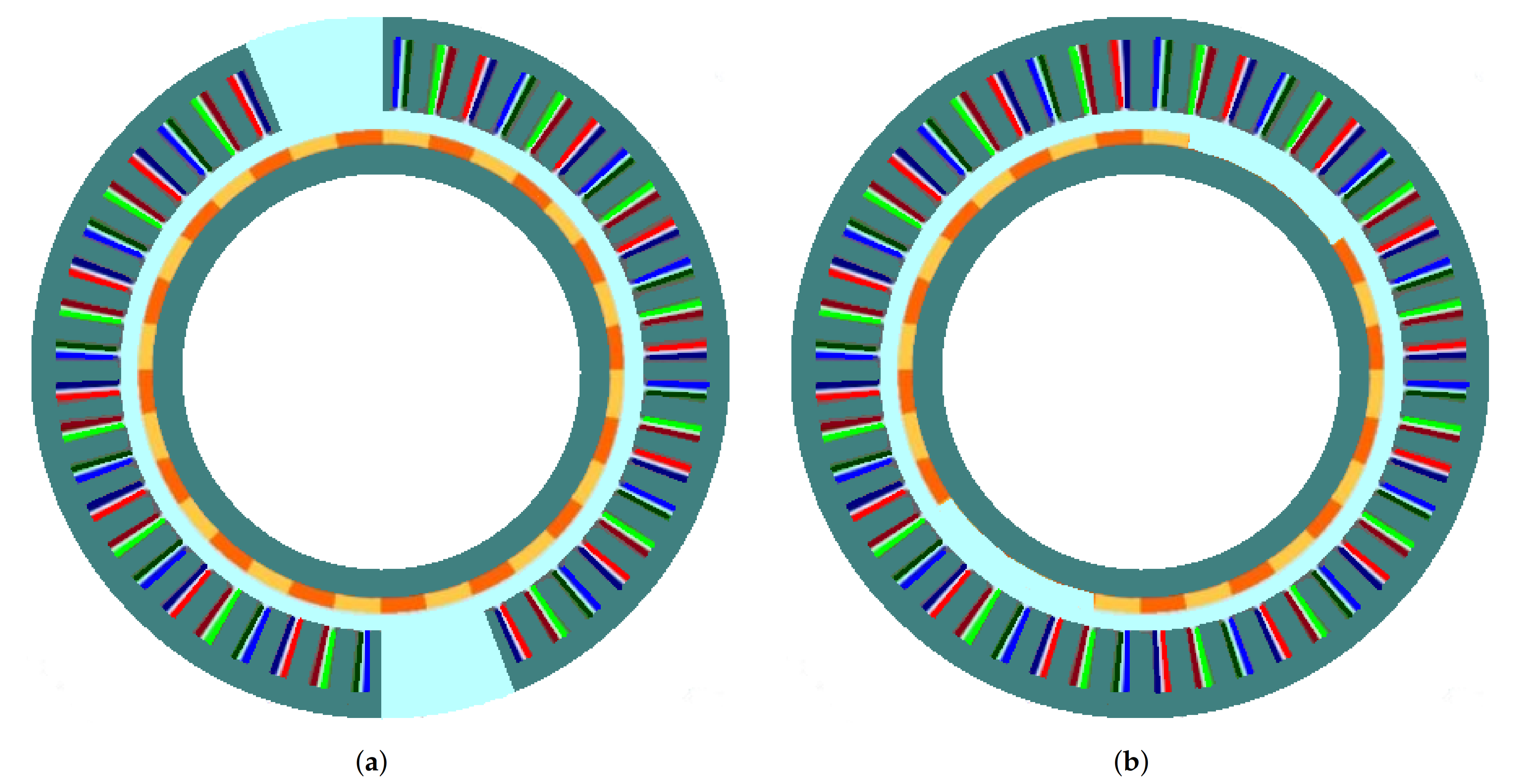
The presented study deals with unconventional structures of Permanent Magnet Synchronous (shortened as PMS) electrical machines. In the following, these machines are called segmented machines. Studies of these kinds of machine appear in the literature for some years [1,2,3,4]. In these particular structures of electrical machines, the stator [1,2,3] or the rotor [4] is divided into several parts which contain active parts (named sectors) which are separated by non-active areas (called gaps and which does not contain active parts). Figure 1 presents structures with a segmented stator or a segmented rotor with n s = 2 sectors. The ratio between total gap width and circumference is equal to p g a p = 0.125 for the stator-segmented structure and p g a p = 0.25 for the rotor-segmented machine.
The gaps can be filled with amagnetic materials (for example, specific resin) or soft ferromagnetic materials (iron laminations). Indeed, using ferromagnetic materials in the gap leads to a better cooling than if non-metallic gaps are used because the internal heat sources (losses) can be evacuated by these non-active metallic parts.
These very unconventional structures can be used to reduce the losses part related to the end-windings in very large diameter electrical machines with small axial length and/or to increase efficiency and reliability [5,6]. These structures can be for example used in Rim-Driven machine for tidal turbine or marine propeller where the machine diameter is directly linked to the turbine or propeller external diameter.
Test cases corresponding to a high power Rim-Driven generator for tidal turbine are considered. In a Rim-Driven system, the electric generator active parts are located in a duck surrounding the turbine blades. In this configuration, if a non-segmented design is used for a Rim-Driven turbine, the axial active length of the electrical machine is very small and the majority of copper is located in the end-windings (almost 80% for the non-segmented reference machine presented in [7]). This is why segmented stator PM machines have the expected advantage to reduce the part of the end-windings copper volume and so the global copper losses into Rim-Driven systems as shown in [5]. Furthermore, these low-speed generators have a high number of pole pairs which allow many rotor and stator segmentation possibilities. Rotor-segmented structures are proposed here to reduce the mass of magnets. Only structures with segmented stator or segmented rotor with amagnetic gaps are studied in this paper. The combination of both segmented structures is not studied in this paper.
This article is a significantly extended version of the conference paper presented in Compumag 2019 [6], where an estimation of cogging torque in the case of a segmented stator was studied based on the same non-segmented reference machine.
To estimate the electromagnetic performances of an electrical machine, a Finite Element Method (FEM) could be used. In the case of a segmented structure, the increase of the simulation domain leads to increase the computation time. In order to evaluate the performances in a faster way, analytical models could be used. Those ones can be useful at the pre-design step or can be integrated into a systematic design process. Analytical magnetic flux density, cogging torque, electromotive forces, and global torque calculation models have been presented and used in the literature for classical non-segmented slotted machines. In the presented work, these models are modified to be adapted for stator-segmented structures and rotor-segmented structures. Original analytical methods which are presented in this paper allow precise and fast estimation of the EM performances of such structures. They allow also estimating the impact of the suppression of active parts of the stator or the rotor. A sensibility analysis is done for different gap ratios and different numbers of gaps to estimate the validity domain of the proposed methods.

2. Context, Hypotheses and Segmentation Protocol

In this paper, large diameter PMS machines with a high number of poles and with surface mounted radially magnetized magnet are considered. This kind of machines are widely used in naval propulsion application or associated with tidal or wind turbines for renewable power generation [7,8]. In these kinds of applications, as shown in [5], introducing segmentation can lead to significant improvements in terms of performances and/or reliability. The segmentation consists of removing some active parts (in the stator or in the rotor), like coils, permanent magnets and/or yoke. For the stator segmentation, coils and the corresponding part of the stator magnetic circuit are removed and replaced by an amagnetic material (amagnetic gaps). For the rotor segmentation: the magnets and the corresponding part of the magnetic circuit are removed and replaced by amagnetic materials (amagnetic gaps).
Large segmentations with gaps larger than one pole pair are considered. In fact, to keep the windings and flux balanced, entire number of pole pairs (for rotor segmentation) and entire number of winding periods (for stator segmentation) are removed. This is why the considered hypothesis and proposed models fit well with large diameter machines with a high number of pole pairs. Indeed, a high number of pole pairs allows a large number of segmentation possibilities. The segmentation topology can be defined by two parameters: the number of introduced gaps in the circumference n g a p , and the gap ratio p g a p . The considered structures comprise n g a p gaps with the same angular width. These n g a p gaps are regularly distributed in the structure circumference. The gap ratio p g a p corresponds to the proportion of the gap angular parts in regards to the entire circumference of the machine. So p g a p = 0 corresponds to the classical machine without angular gaps, and p g a p = 1 would correspond to a hypothetical machine without stator (or rotor).
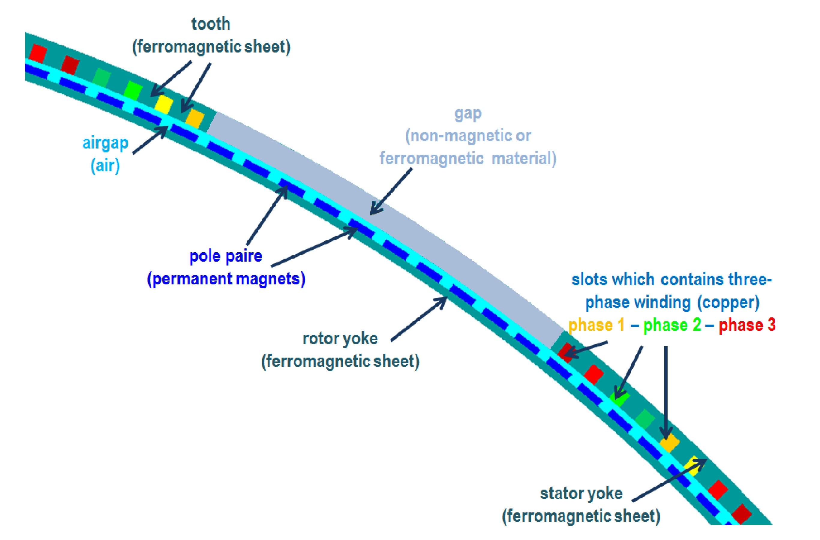
Figure 2 presents a part of a stator-segmented machine (with concentrated windings) where the different parts of the machine are described. Figure 3 shows the different structures which are studied in this paper: non-segmented machine Figure 3a, stator-segmented machine with amagnetic gaps Figure 3b and rotor-segmented machine with amagnetic gaps Figure 3c.

3. EM Analytical Model

3.1. EM Models for Non-Segmented PMS Machines

For a clearer understanding of the original contributions of the presented work, firstly, existing methods dedicated to classical non segmented PMS are briefly presented. This is why this subsection is a brief description and reminder of the known analytical methods for calculating the EM performance of classical non-segmented PMS machines which will be adapted to the case of segmented structures in order to establish new models dedicated to segmented structures. It can be noted that for all the presented analytical models, the iron core material magnetic permeability is classically considered to be infinite (in fact the influence of the value of the iron permeability is negligible because iron permeability is very high compared to other material permeability).

3.1.1. Magnetic Flux Density Due to PM

B / R wich is the flux density located in the air gap can be calculated analytically for an equivalent slotless machine B / R s l . In this case the resolution of Poisson equation by variable separation allows to obtain the classical expression of this flux density as a Fourier Series which is given in this reference paper [9]. A permeance function λ ( θ ) is used to take into account the variation of magnetic flux density in the slot openings (1). Then the flux density generated by rotor permanent magnets in the air gap (at a (r) radius) is given by (2).
λ ( θ ) = h g + h m μ r h g + h m μ r + r f l ( θ ) π 2
B / R = B / R s l ( r , θ ) × λ ( θ )
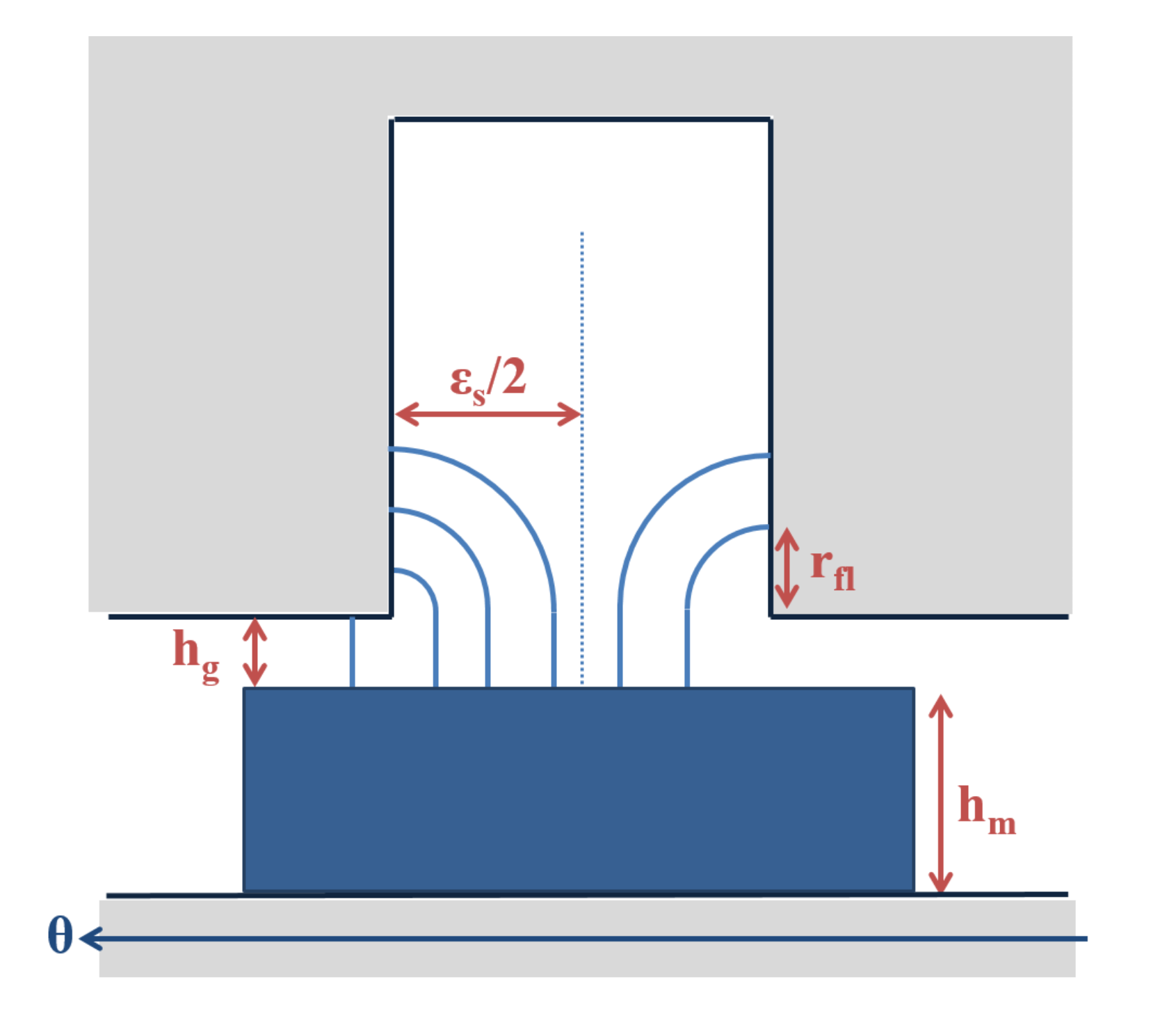
In (1), h g , h m and μ r are the air gap and magnet thicknesses and magnet magnetic permeability, respectively. r f l π 2 is the flux line additional length located inside the slot opening area (as shown in Figure 4). The considered flux lines used are considered as circular arcs in the slot openings areas.
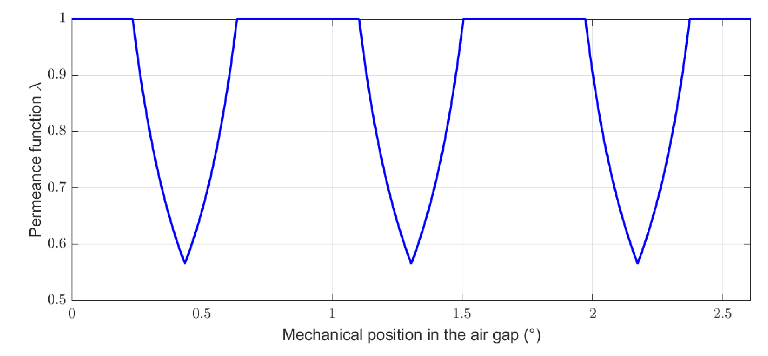
Figure 5 presents the relative permeance function for the non-segmented machine used in the validation section (Section 4.1.1) for an angular width corresponding to one pair of poles (this machine has 414 slots and 138 pole pairs with non-closed slots and a ratio between slots and slot period equal to slot to β s = 0.46).

3.1.2. Cogging Torque

An analytical cogging torque model is presented in [10]. In this model, the calculation of cogging torque is based on the estimation of the magnetic pressure applied on each slot opening frontiers. The magnetic flux density created by the rotor B / R is first evaluated in each stator openings and the contributions of each slot frontier are added as shown in (3), for a position of the rotor θ r .
T c , s l o t t e d ( θ r ) = L z 2 μ 0 × 1 Q s 0 ϵ s 2 ϵ s B / R 2 ( θ ) × ( R s + r f l ( θ ) ) d θ 0 ϵ s 2 B / R 2 ( θ ) × ( R s + r f l ( θ ) ) d θ
In the Equation (3), ϵ s is the slot-opening width and r f l is an additional length corresponding to the flux line radius applied on the slot side at the position θ as shown in Figure 4. R s is the internal stator radius, L z is the iron axial length of the machine, μ 0 the permeability of free space and Q s is the number of slots.

3.1.3. Electromotive Forces and Electromagnetic Torque

A classical method to determine electromotive forces (EMF) E i (4) is based on the estimation of the no-load flux ϕ i (5) of each phase [7].
E i ( θ r ) = d ϕ i ( θ r ) d θ r
ϕ i ( θ r ) = R s × L z θ = 0 2 π W i ( θ ) × B / R ( θ , θ r ) d θ
In (4) and (5) θ r = Ω t , Ω , and W i ( θ ) are the rotor position, rotor speed and winding function of the phase i, respectively.
The knowing of the EMF allows the determination of the electromagnetic torque T e m by (6).
T e m ( θ r ) = i = 1 m E i ( θ r ) × I i ( θ r ) Ω
E i ( θ r ) and I i ( θ r ) are, respectively the EM forces and the currents associated with the phase i, and m is the number of phase.

3.2. New Models for Stator-Segmented Structures

The EM models presented for non-segmented machines (magnetic flux density, cogging torque and electromotive forces) are adapted for stator-segmented structures in this section.

3.2.1. Magnetic Flux Density Due to PM

For the stator-segmented structure, the flux density B / R is calculated from the Equation (2) (as in [9]). For the studied segmentation, the classical relative permeance function λ ( θ ) is considered and adapted to take into account the effects into the gaps in addition to the flux density attenuation related to the slot openings. The approach is an extension of the classical permeance function (1) by considering that the gap is a large slot, with opening-slot higher than the pole pitch, as illustrated by Figure 6.
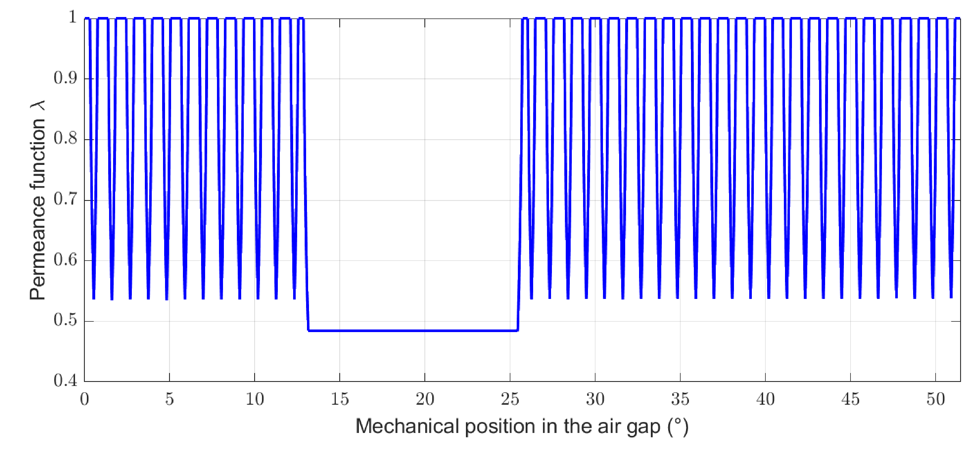
Figure 7 presents the obtained relative permeance function for the segmented-stator machine considered in the following (7 gaps, 336 slots, 140 pole pairs, and p g a p = 0.25).
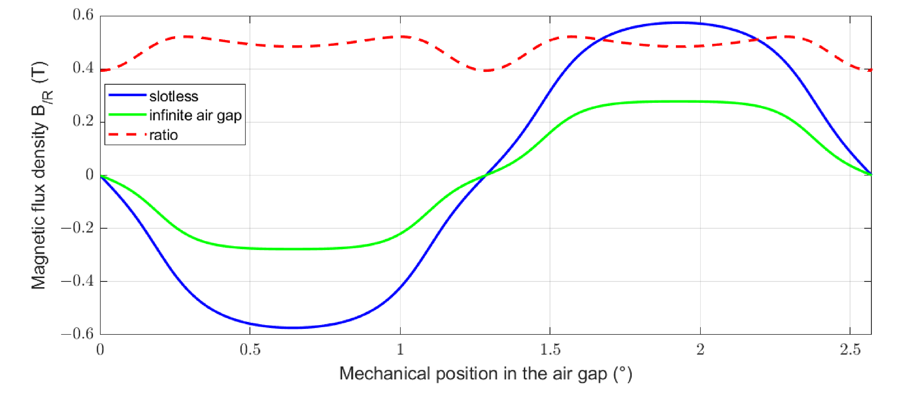
The contributions related to the slots and to the gaps can be distinguished: the periodic waveform (waveform variation from 1 to about 0.54) correspond to the effects of the slots (obtained by the classical methods), whereas the variation between 13 and 26 degrees results from the effects of a gap. The lower value of the permeance function in the gap is determined for each structure dimensions set. This value corresponds to the ratio of the magnetic flux density of permanent magnet without ferromagnetic part in front of rotor (noted “infinite air gap”) with the magnetic flux density in a slotless machine with the corresponding dimensions as shown in Figure 8. This value is determined in a first step by analytical calculation for the two configurations (slotless and infinite air gap). For the considered test case, this ratio is equal to 0.48. This approach has been validated by numerical calculations using FluxTM 2D.

3.2.2. Cogging Torque

In a stator-segmented structure with a amagnetic gap, the cogging torque is due to PM electromagnetic interaction with the sectors/gaps in addition to the interaction with slots/teeth. So it is necessary to determine the contribution of gaps to the cogging torque.
  • Superposition principle
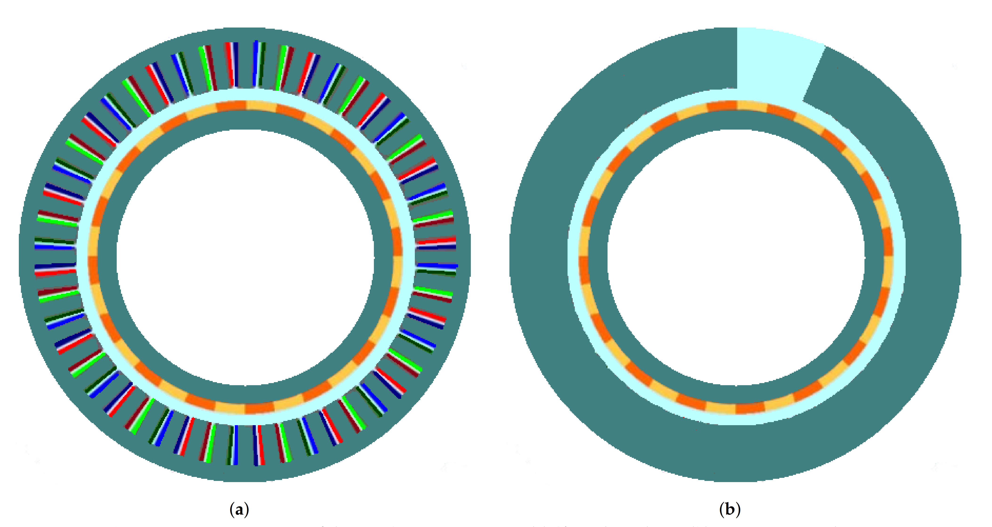
    The estimation of the cogging torque for a segmented structure is based on the superposition principle [11]. It is assumed that the contributions of slots and angular gaps to the cogging torque are independent and can be added. The cogging torque is evaluated for two basic structures: a non-segmented slotted machine with the same geometry as the studied segmented machine, and a structure with the same dimensions with no slot and with only one gap on the stator (named mono-gap structure). An example of this theoretical mono-gap configuration is presented in Figure 9b. The contribution of slots and angular gaps are estimated separately and then added. The classical analytical model for calculating the cogging torque (as in [10]) is used to estimate the first contribution (due to slots).
    For the proposed mono-gap model, it is supposed that angular gaps contain entire number of pole pairs. In fact, to keep a regular winding distribution, the gap angular width must be a multiple of the winding period which corresponds to a number of slots defined by Equation (7) and called reduced number of slots.
    Q s 0 r e d = S p p × 2 × p 0 p p c m ( Q s 0 , p 0 ) × m
    In this equation, S p p is the number of slots per pole and per phase.
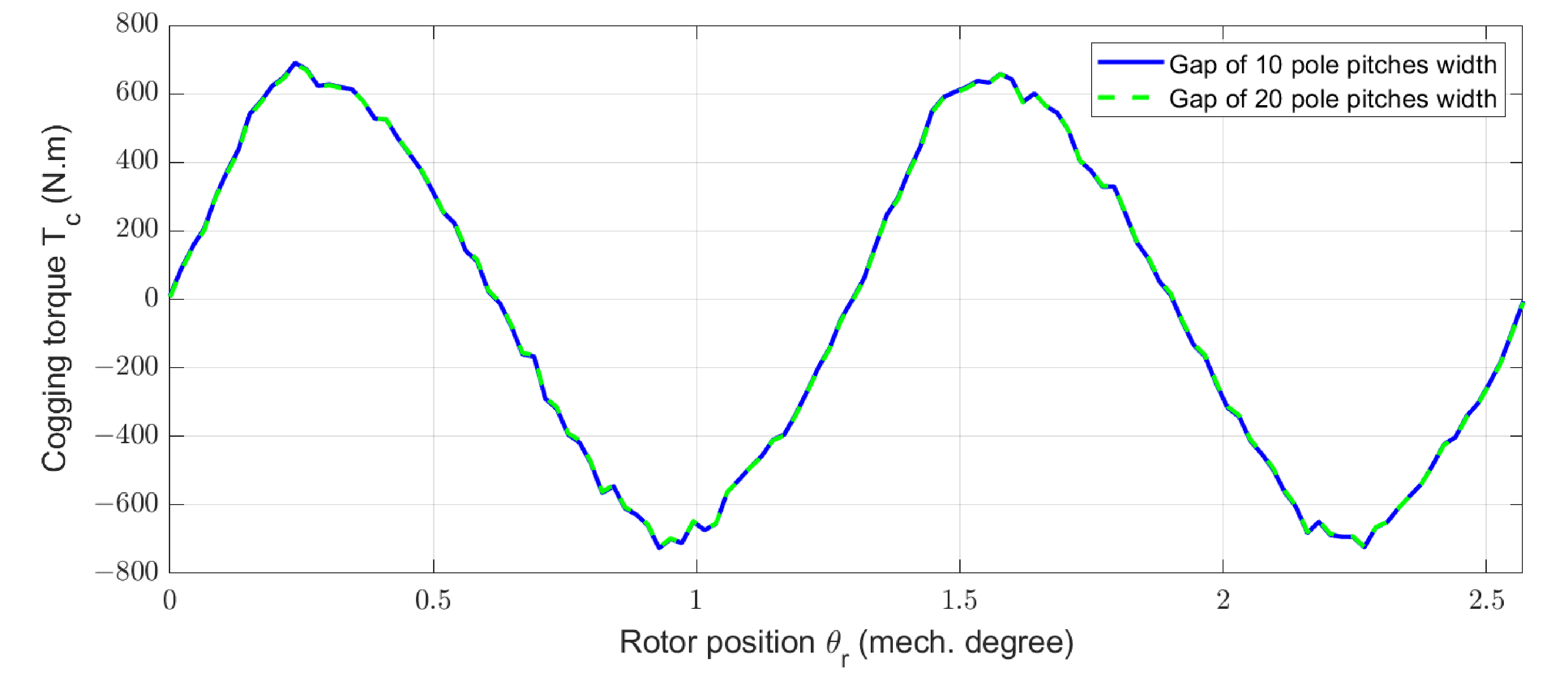
    2D FEM (with the software FluxTM 2D) is used in a preliminary step to validate the mono-gap model. This numerical study shows that the gap width does not influence the cogging torque peak value nor its frequency for a mono-gap structure, if the gaps contain entire number of pole pair. Figure 10 presents the cogging torque calculated by 2D FEM for two single-gap structures with the same geometry (as depicted in Figure 9b) and two different gap widths, in function of the rotor position θ r . It can then be seen that the contribution of one gap to the cogging torque is the same for similar structures with several gap widths.
    For a stator-segmented structure, the cogging torque is estimated for the whole slotted machine T c , s l o t t e d (Figure 9a) (with the Equation (3)). This contribution is multiplied by the active part proportion ( 1 p g a p ) . In addition, the mono-gap contribution to the cogging torque T c , M o n o G a p is evaluated and multiplied by the number of gaps n g a p included in the structure, as shown by (8). This calculation method is valid because all the gaps are in the same relative position relatively to the rotor poles.
    T c , S t a t o r G a p ( θ r ) = T c , s l o t t e d ( θ r ) × ( 1 p g a p ) + T c , M o n o G a p ( θ r ) × n g a p
  • Mono-gap cogging torque estimation
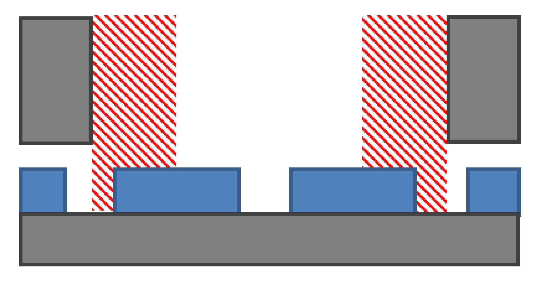
    The proposed mono-gap model to evaluate the cogging torque is based on the classical analytical calculation for a non-segmented structure presented in [10]. The estimation of the mono-gap cogging torque depends on the magnetic pressure in each active sector/gap interface. The calculation is done on the red shaded area of the Figure 6. This calculation area corresponds to half a pole pitch in each gap extremity. The method is extended to the stator-segmented machine by using the flux density created by permanent magnets into gaps and the extended permeance function adapted for gaps in the stator.
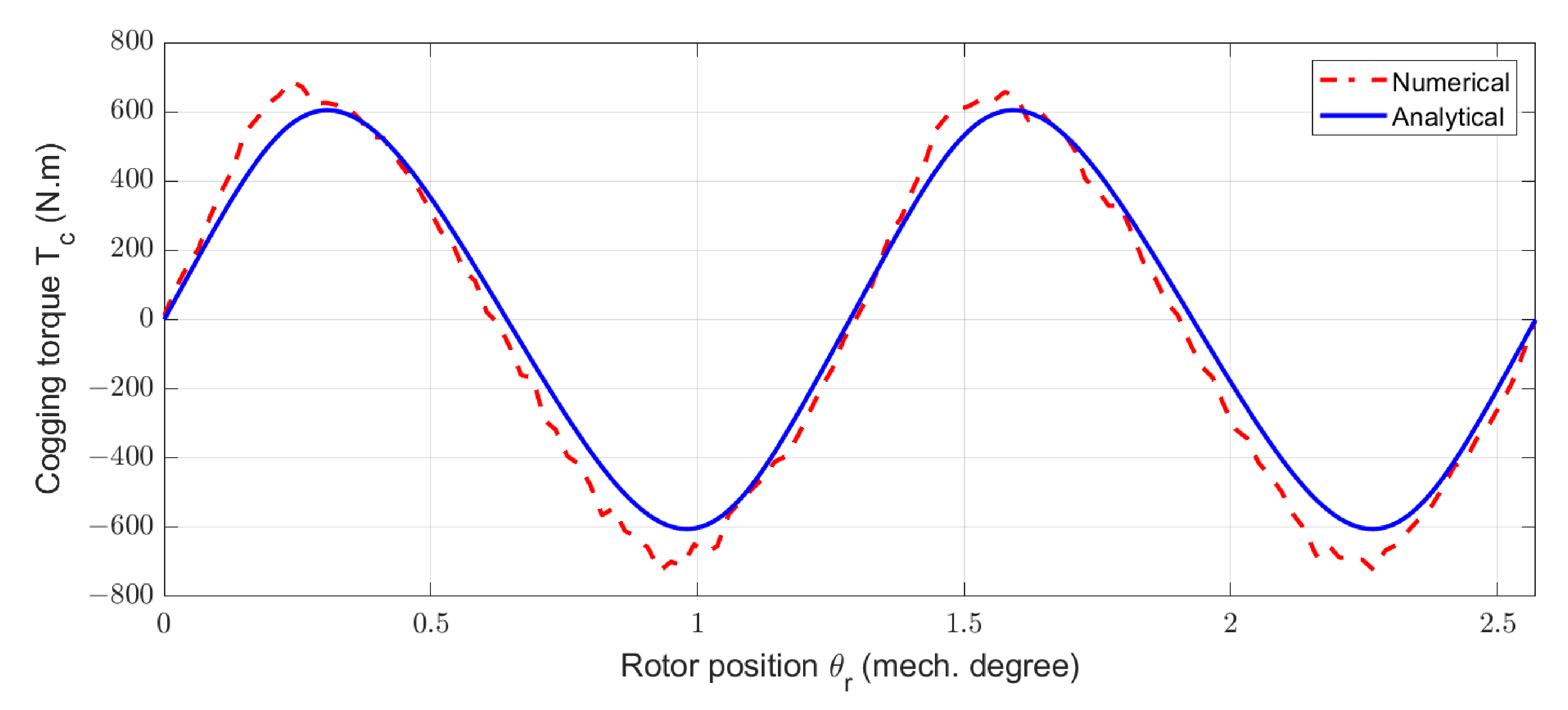
    The proposed mono-gap model is validated for the mono-gap structure used for the previous numerical study (Figure 10). Figure 11 presents the mono-gap cogging torque obtained with the numerical (2D FEM) and proposed analytical methods for a mono-gap machine with a gap width of ten pole pitches.
    For the test case of a large diameter structure, the proposed analytical mono-gap model gives good evaluations of the cogging torque related to the mono-gap effect.

3.2.3. Electromotive Forces

The suppression of some coils impacts the electromotive forces. From the knowledge of B / R s l and the new permeance function, the model (4) for the entire machine (i.e., all the coils) is used and only the proportion of active parts and so the proportion of coils in the segmented machine is taken into account.

3.3. New Models for Rotor-Segmented Structures

In this section, the magnetic flux density, cogging torque and electromotive forces models presented for non-segmented machines are adapted for rotor-segmented structures.

3.3.1. Magnetic Flux Density Due to PM

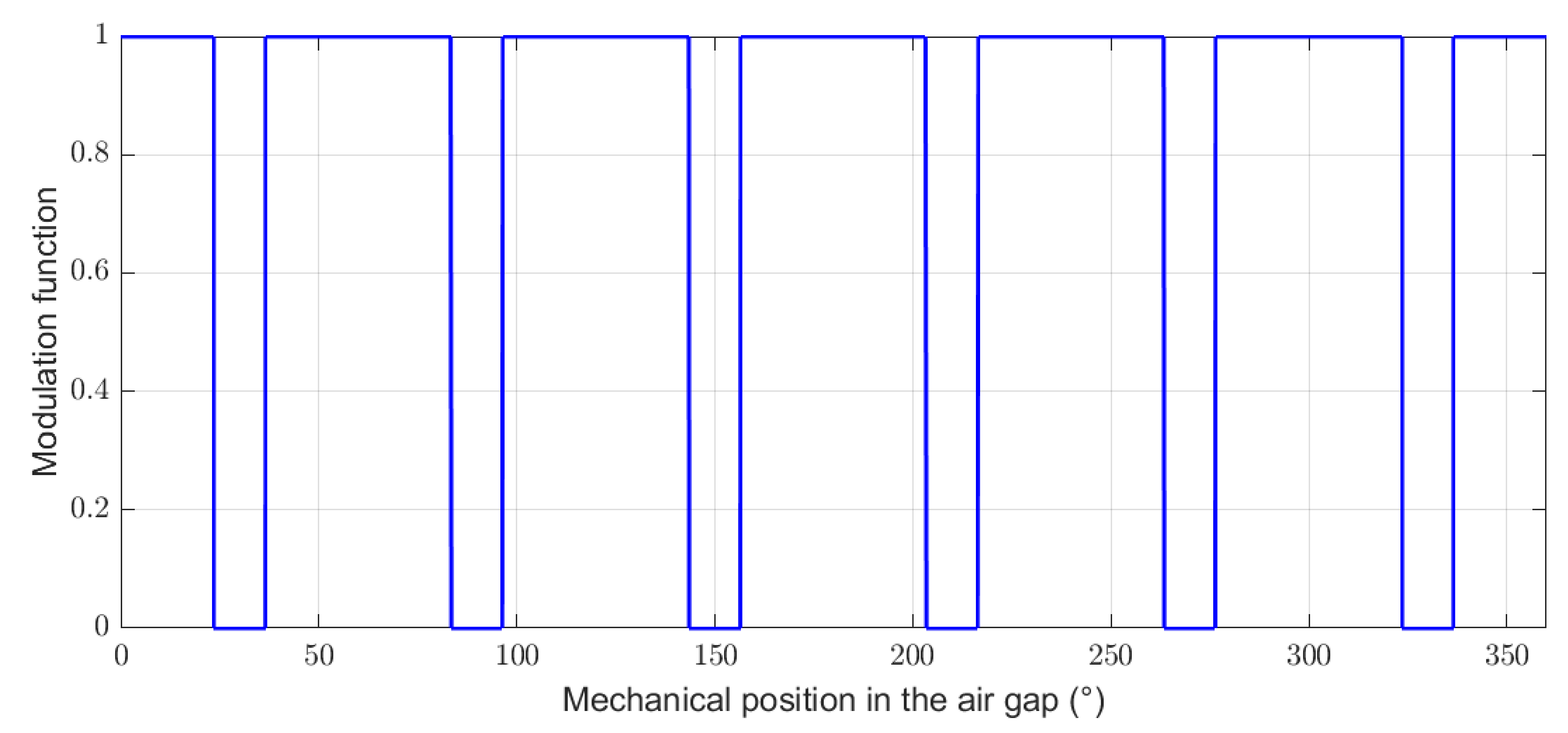
A modulation function which is 1 where there are magnets and 0 in the parts where the magnets are removed (gaps) [12,13] is used. This kind of modulation is also used to model salient pole machines.
Figure 12 presents the modulation function in the case of a machine with six gaps regularly distributed over the circumference of the rotor and with p g a p around 20%.

3.3.2. Cogging Torque

Considering previous assumptions, the cogging torque of rotor-segmented structures expression (3) is modulated by the active part proportion ( 1 p g a p ) (9).
T c , R o t o r G a p ( θ r ) = T c , s l o t t e d ( θ r ) × ( 1 p g a p )

3.3.3. Electromotive Forces

The rotor segmentation does not modify the winding of the machine. However, only the coils in front of magnets are taken into account. The classical model (4) is also modulated by the active part proportion ( 1 p g a p ) .

4. Validation

4.1. Methods and Objectives

In the case of segmented machines, the use of numerical simulation can be highly time consuming because the segmentation leads to a strong increase of the calculation domain which is directly related to the spatial periodicity of the studied EM structure. This is why, if EM models have to be used in a systematic design method (optimization for example), fast and accurate models as the proposed analytical methods are needed. This is why, a comparison with numerical simulations is achieved to validate the proposed model and parametric variations are done. The main objective is to demonstrate the ability of the presented analytical approach to correctly take into account the effects of the parameter variations with a good accuracy.

4.1.1. Non-Segmented Reference Machines

The segmented structures are based and compared to a reference machine design with a non-segmented structure. This reference machine has been previously designed by our team in previous works and corresponds to the specifications of a 300 kW/15 rpm Rim-Driven generator for tidal turbine [7]. The stator internal diameter value is, in this case, equal to 11.151 m. In this reference design, around 80% of copper volume (and consequently Joule losses) corresponds to the end-windings parts. These large losses leads to a significant reduction of electrical machine efficiency. In order to solve this problem, unconventional machine structures with segmentation of active parts can be an interesting solution. The common characteristics of all the studied machines (segmented and non-segmented structures) are presented in Table 1.
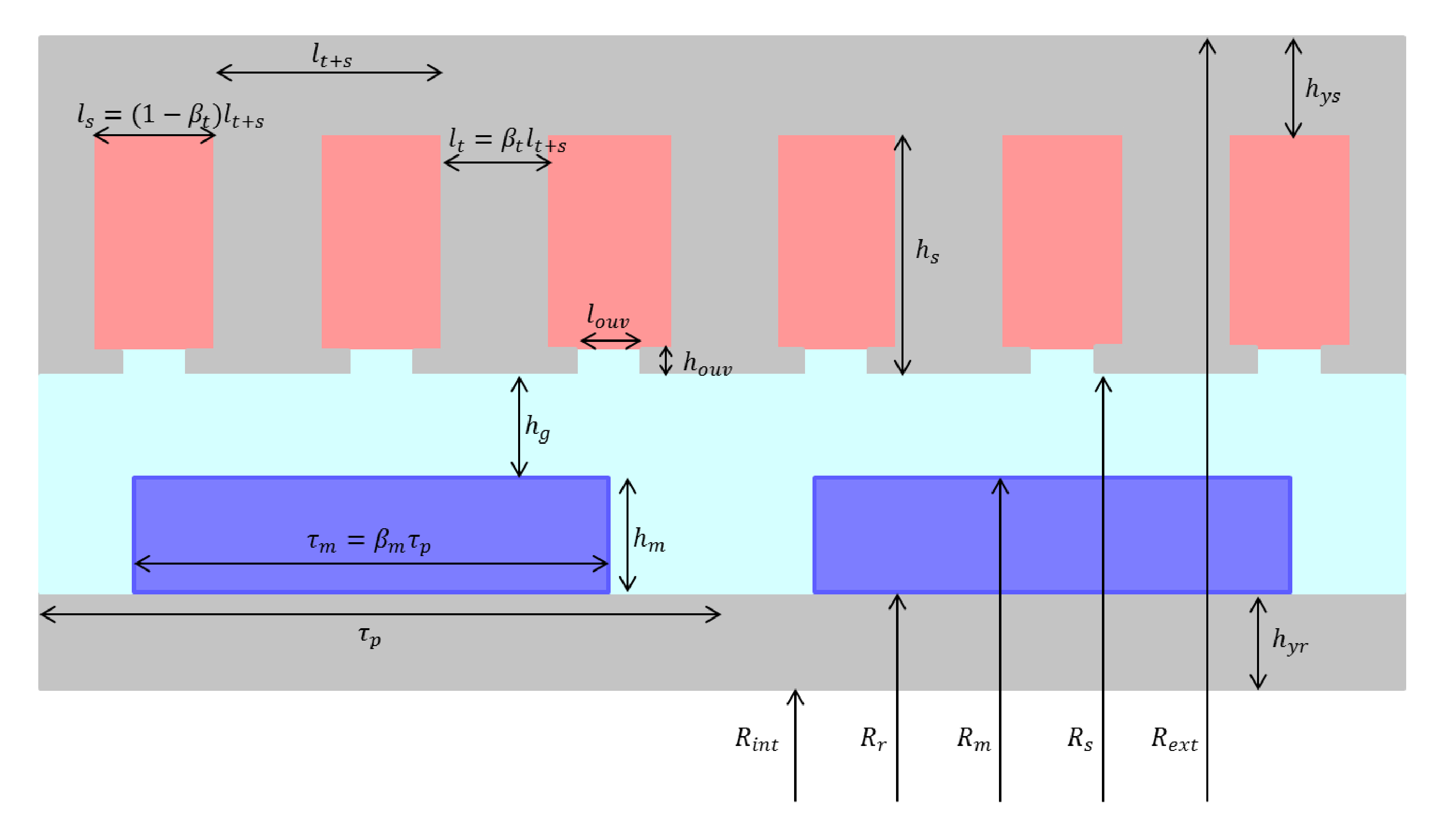
To reduce copper volume, a first machine, directly derived from [7], is proposed with a concentrated winding (with a number of slot per pole and per phase equal to S p p = 1/2). Thus, the geometric parameters are determined to have a half slot per pole per phase. This machine (named RS-machine) will be used to study the rotor segmentation effects. Because the winding of this first machine is not divisible due to a two layers winding topology, a second machine (named SS-machine) is proposed to study the stator segmentation. This machine is also derived from [7] and keeps the characteristics given in Table 1. The winding is modified and a machine with a fractional number of slots per pole and per phase equal to 2/5 is chosen. The choice is motivated by the 1st harmonic winding coefficient close to 1 [14] and a relatively small winding periodicity (10 poles). In this case, the number of pole pairs should be slightly modified. Table 2 and Table 3 present the different geometric parameters determined for both reference machines. Figure 13 depicts these geometric parameters.
Studies of this kind of machine with large diameter, large air gap, and a small axial length, like Rim-Driven systems, show that strong leakage 3D effects on the axial ends of the machines modify the EM behavior of the structure. Due to this phenomenon, 2D calculation (numerical and analytical) overestimates the magnetic fluxes, EMF or torque. In [15], a correction factor ζ 3 D corresponding to the relative error related to the 3D effects is introduced. The relative error depends on the magnetic air gap length magnetic air gap length, g m (which includes both mechanical air gap and magnet height) to the axial length L z 0 ratio. The expression of the corrective factor is given by (10).
ζ 3 D = 1 0.2 × g m L z 0
Including this corrective factor, Equation (11) expresses the EM torque.
T e m = ζ 3 D × 2 × k w × A L × B 1 × c o s ( ψ ) × L z 0 × π D 2 4
B 1 corresponds to the fundamental of the air gap flux density (due to rotor at no load) and is estimated using 2D analytical method as in [9]. k w is the first harmonic winding coefficient (see Table 2 and Table 3), and A L is the linear electric loading.
Equation (11) is considered to determine the axial length (12) for the EM torque corresponding to specifications of Table 1. For all the studied cases, the magnets and the air gap are the same, thus the value of B 1 is considered as constant, the linear electric loading A L given by the Equation (13) is also considered as constant (see Table 1).
L z 0 = T e m ζ 3 D × 2 × k w × A L × B 1 × c o s ( ψ ) × π × D 2 4
A L = n c d × I × Q s 0 π × D
In Equation (13), I is the current RMS and ψ is the angle between the stator current and the induced EMF. The axial length values presented in Table 2 and Table 3 already are determined using this methodology.

4.1.2. Segmented Machines Test Cases

The studied segmented structures (both stator and rotor segmentation) corresponds to the same specifications than the two reference structures of Table 2 and Table 3. All the parameters of Table 2 and Table 3 except the axial length are kept constant.
In the case of a stator-segmented structure, the expression of the average linear electrical loading became (14) where n c d is the total number of conductors per slot.
A L = n c d × I × Q s π × D = n c d × I × Q s 0 ( 1 p g a p ) π × D = A L × ( 1 p g a p )
In fact a global linear electric loading A L , which will varie to be proportional with ( 1 p g a p ) , is introduced in the torque equation without considering the 3D correction factor (15). The local linear loading, A L , is maintained as constant ( A L is in this case the linear loading in the stator sector parts). In fact, to maintain, at first order, the same thermal behavior of the statoric parts for all the studied structures, A L and J (current density in the conductors) are kept identical for all the studied cases (heat sources are supposed only located in the stator windings and heat is supposed to be evacuated radially).
T e m = 2 × k w × A L × B 1 × c o s ( ψ ) × L z 0 × π D 2 4
To keep a constant torque, a new preliminary iron axial length, L z needs to be recalculated as a function of the segmentation rate p g a p (16).
L z = T e m 2 × k w × A L × ( 1 p g a p ) × B 1 × c o s ( ψ ) × π × D 2 4
It can be noticed that the 1st harmonic of the no-load air gap flux density B 1 does not vary with p g a p . However the corrective factor ζ 3 D depends on the axial length (10), and thus depends on the gap ratio p g a p .
For each preliminary axial length, L z , found for the different p g a p value, a corrective factor is calculated with the Equation (10). Thus this preliminary axial length is divided by the corresponding correction value ζ 3 D to have a final axial length, L z , that take into account the end effects in the segmented machine (Equation (17)).
L z = L z ζ 3 D ( L z )
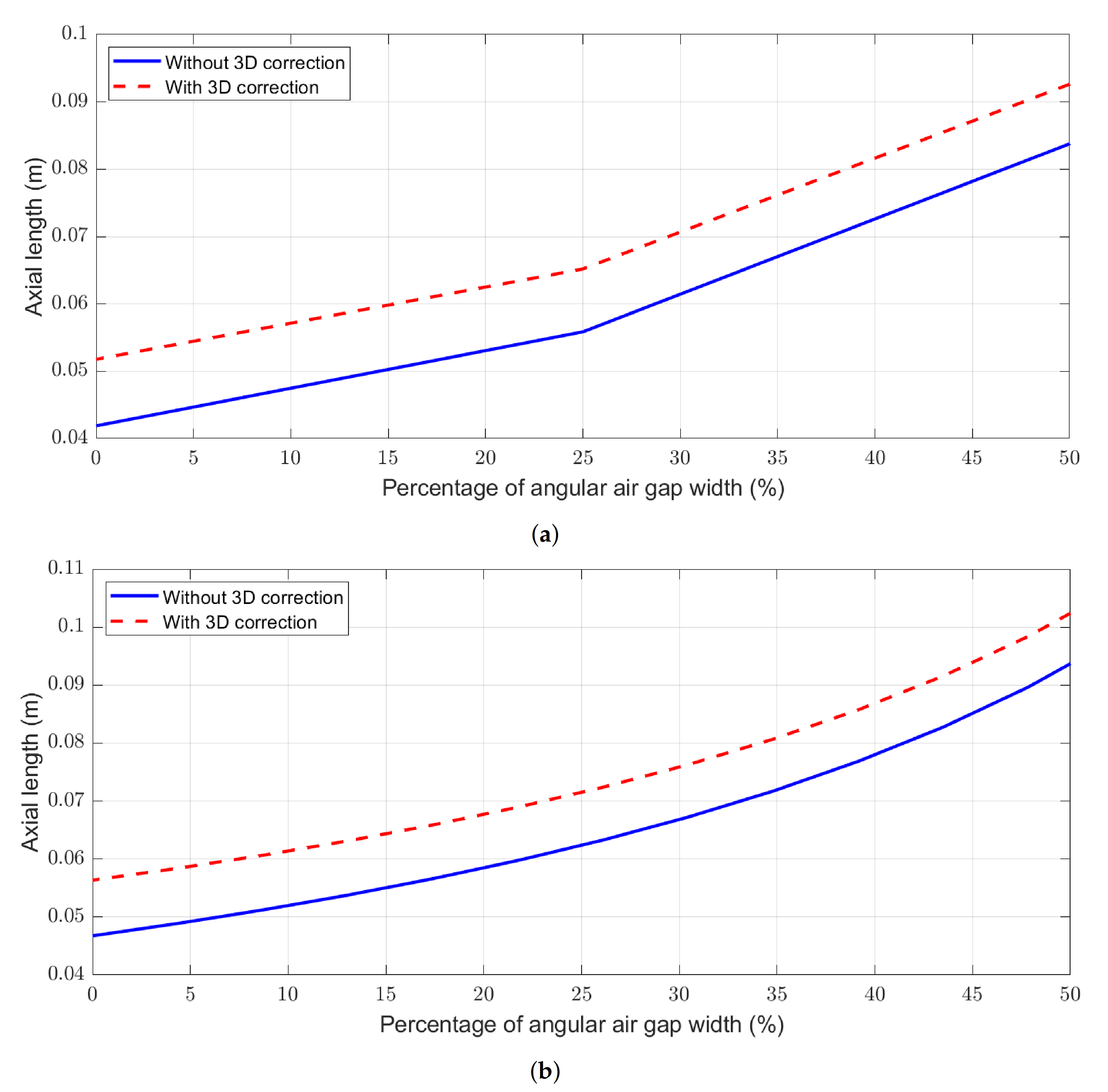
Figure 14 shows the evolution of the axial length depending on the proportion of segmentation, with and without considering the 3D correction, for the machines designed for stator segmentation (Figure 14a) and for the ones designed for rotor segmentation (Figure 14b).
It can be noticed that the suppression of the active part is compensated by the increase of the axial length. In other words, with the increase of p g a p , the removed part due to the segmentation is added at the end of the machine in order to obtain the same torque performances. The relative parts of 3D effects decrease with the segmentation because higher the axial length value is, lower the relative part of 3D effects is.
For the validation part, the considered gap topologies are presented in the Table 4.
For the p g a p variation, angular gaps are located on the circumference of the machine with a regular distribution, as said in Section 2.
In the case of a rotor-segmented structure, the equations that describe the analytical models presented earlier (Section 3.3), does not depend of n g a p . So the number of gaps does not affect electromagnetic performance estimation like the cogging torque and the electromotive forces for this case. This hypothesis is verified by numerical simulations. The effects of n g a p are negligible for structure with segmented rotor ( n g a p > 0). So the influence of the variation of n g a p is only studied for stator-segmented structures.

4.1.3. Methodology

Magnetic flux density due to PM, cogging torques, electromotive forces, and electromagnetic torques, are calculated using 2D Finite Element Method (2D FEM) and analytical model. Results obtained by analytical and numerical models are compared using several criteria. The first comparison criterion is the correlation value between the numerical and analytical calculated waveforms of the considered EM quantities. As a reminder, the correlation value, C ( x , y ) , between two periodic signals x and y is given by (18) (where x , y is the dot product) [16].
C ( x , y ) = x , y x , x y , y
Peak and mean values of the calculated waveforms corresponding to each considered quantities are also compared.
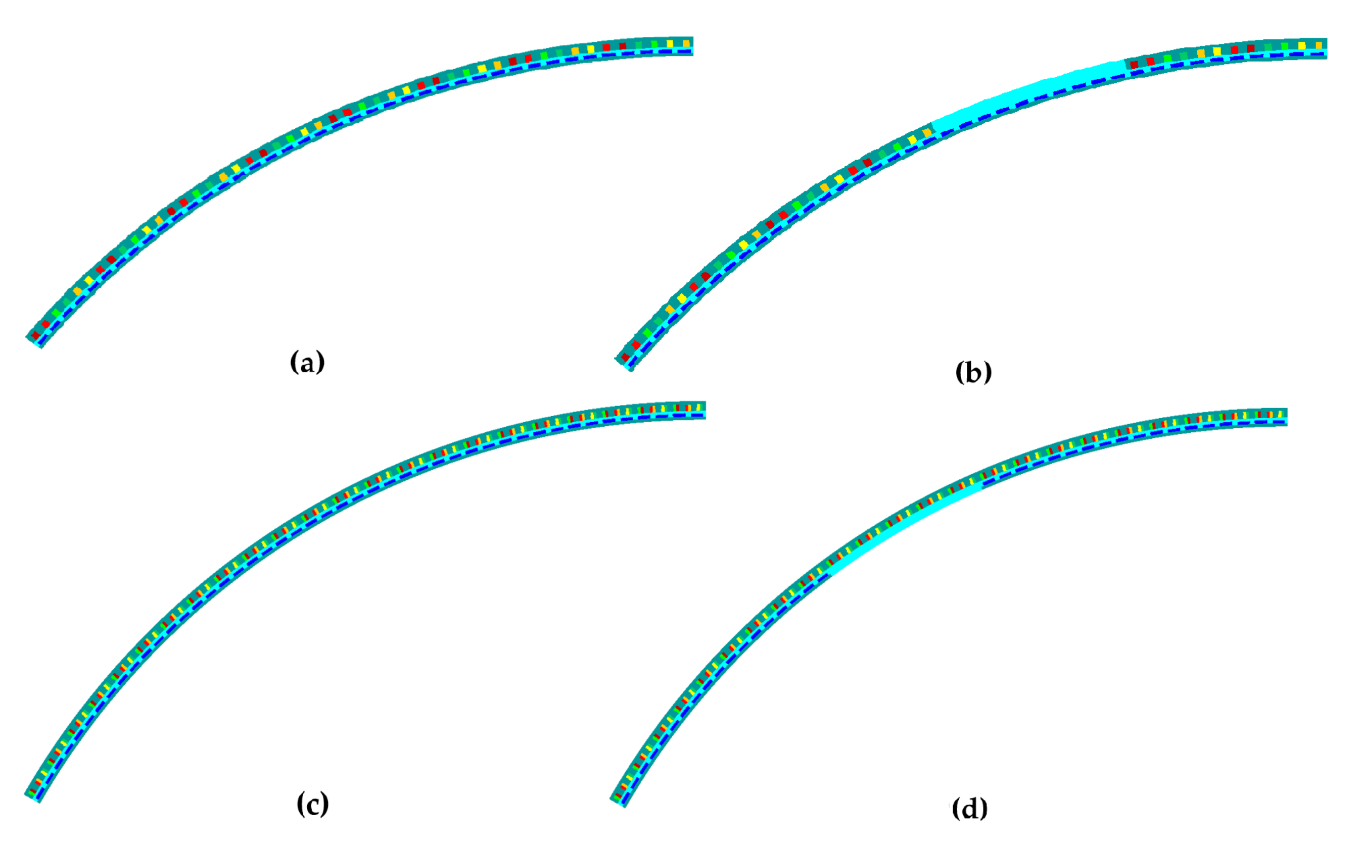
For the RS-machines, if 6 gaps are included, the new period is 1/6th of the machine as shown on Figure 15c,d. Furthermore, if 7 gaps are regularly introduced on the stator of the SS-machine, the new simulation domain should correspond to 1/7th of the whole machine (Figure 15a,b). For the simulation of 1/6th of the RS-machine on the FluxTM 2D software it takes around 15 min, and around 30 min for the SS-machine (simulation of 1/7th of the whole machine) in a Intel(R) Core(TM) i5-6500 CPU with 8 Go of RAM. This time, that it is rather long, attests that a fast calculation procedure can be useful for systematic design processes.

4.2. No-Load Flux Densities

The analytical models presented on the Section 3.2.1 and Section 3.3.1 are used to estimate the magnetic flux density created by magnets in the rotor of the test machines (SS-machines and RS-machines).

4.2.1. Stator-Segmented Case

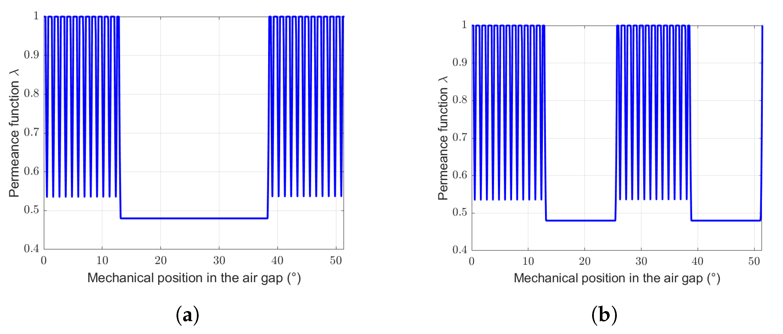
For the estimation of the magnetic flux density created by magnets, it is necessary to adapt the permeance function. Figure 16 presents both permeance function used for the SS-machine with p g a p = 50% and n g a p = 7 and 14 gaps, respectively.
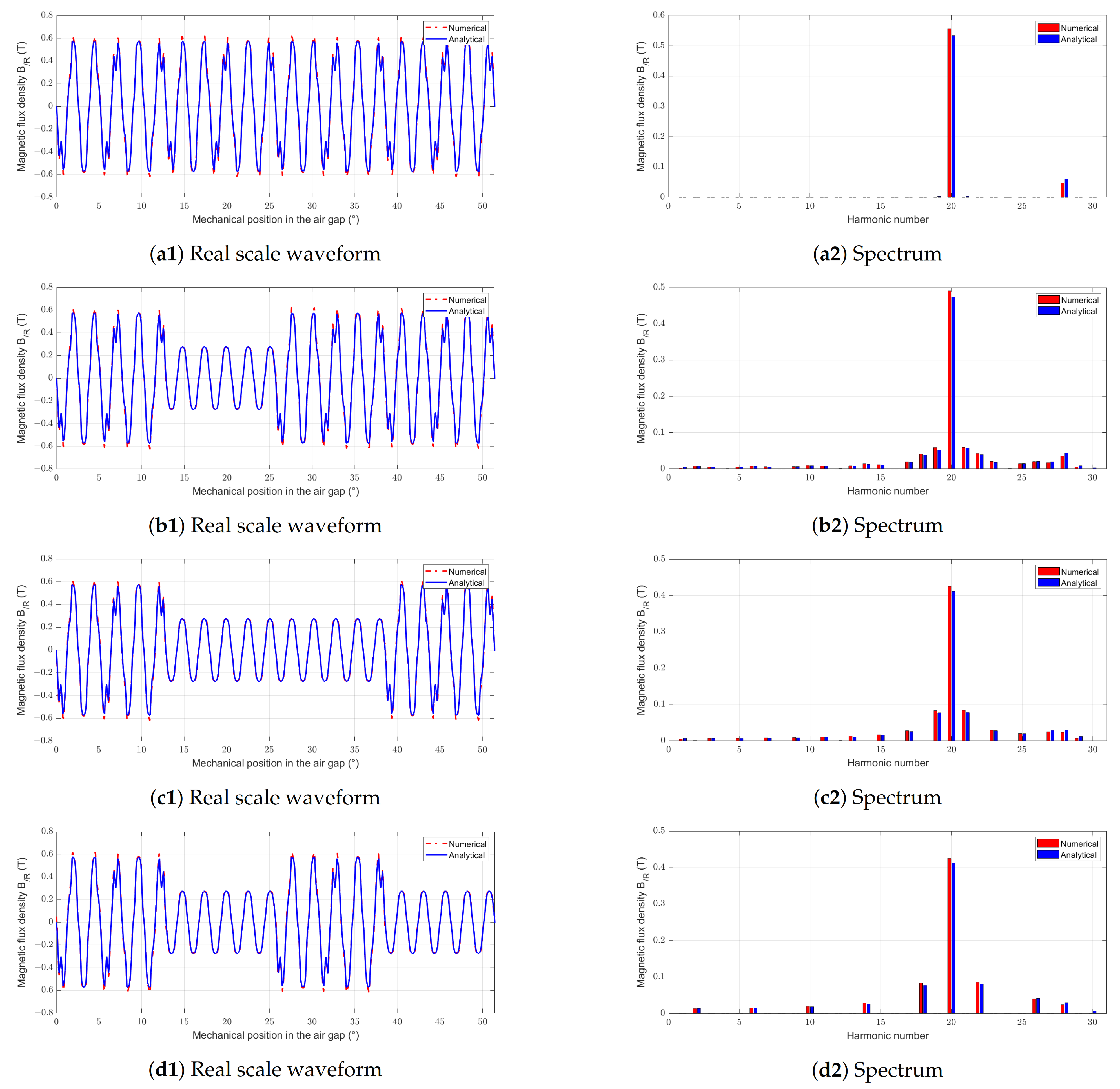
Figure 17 shows the comparison between the magnetic flux density due to PM in the air gap for a fixed rotor position as a function of the angular position, given by analytical and numerical (2D FEM) models for stator-segmented structures with different p g a p and n g a p (waveforms and spectrum).
The use of extended permeance functions for flux density calculation give similar results than numerical simulations. Indeed waveforms are similar, and harmonics contents and values calculated by the two methods are comparable. The permeance function allows replicating well the effects due to slotting, as well as the effect of the amagnetic gaps. The spectral analysis done on the obtained waveforms shows that all the phenomena related to permeance variation are taken into account using the analytical method.
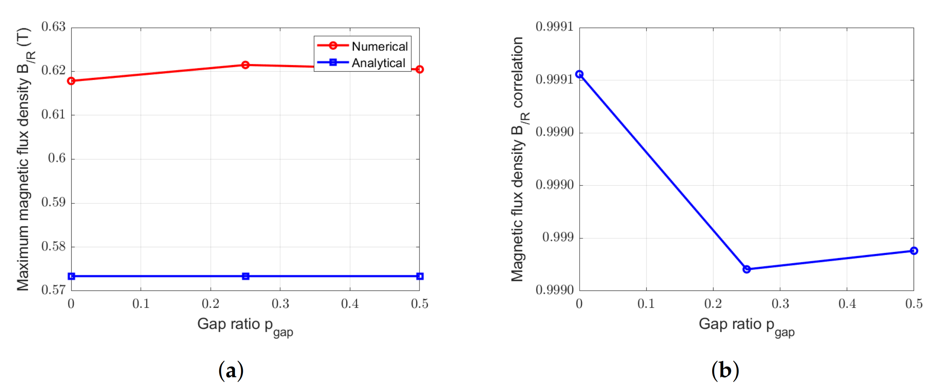
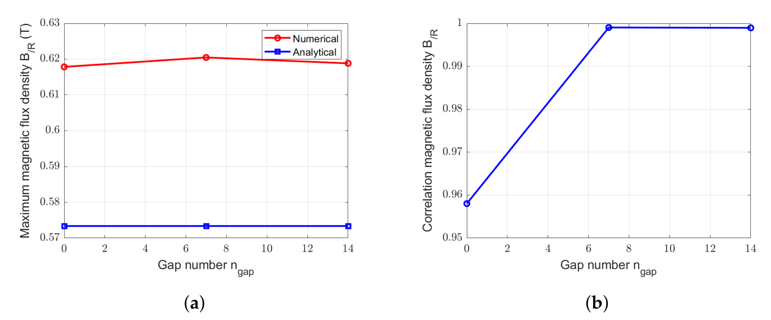
To complete the study, Figure 18 and Figure 19 present the comparison of the peak values for the magnetic flux density created by magnets in the air gap calculated by 2D FEM and analytical model with variations on p g a p and n g a p from the initial design.
There is a small difference between peak values of B / R calculated by analytical and numerical methods which can also be seen in the curves presented in Figure 17. However, the relative difference between the peak values obtained by 2D FEM and analytical model is less than 8%.
Figure 18b and Figure 19b show the correlation between the waveforms of the magnetic flux density due to PM in the air gap given by analytical and numerical models. Results show that analytical model gives a great estimation of B / R in the air gap (stator internal radius) (correlation value greater than 0.99 for all the studied p g a p and n g a p ). However, on one hand, the increase of p g a p leads to a decrease of the correlation value in the case of stator segmentation with a amagnetic material. This is due to approximation on the permeance function related to amagnetic gaps. On the other hand, the increase of the number of gaps leads to an increase of the correlation between analytical and numerical results.

4.2.2. Rotor-Segmented Case

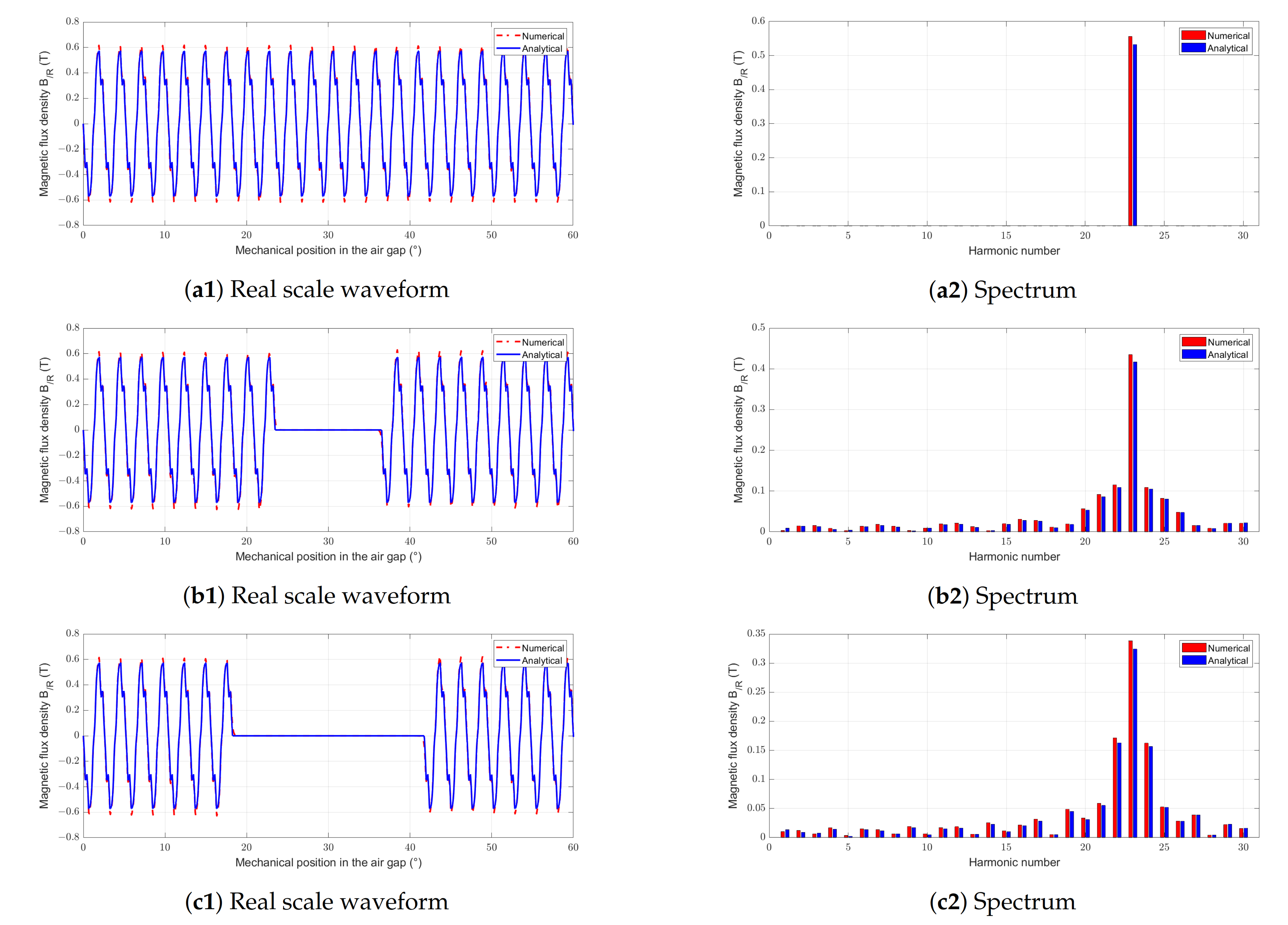
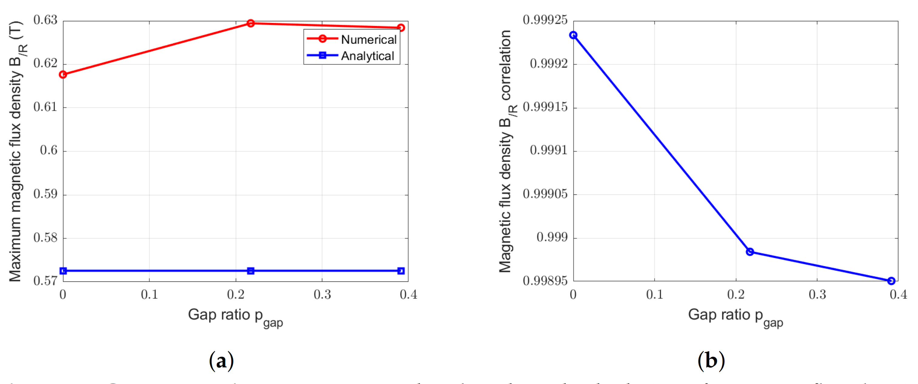
The waveforms and spectral analysis of no-load flux density, in the case of a amagnetic rotor-sectorisation, is presented in Figure 20. In the same way that stator-segmentation, Figure 21 compares peak values and correlation between waveforms obtained by analytical and 2D FE methods for two different gaps ratios.
With the introduction of modulation function (Figure 12), the analytical estimation of the magnetic flux density due to the permanent magnets in the rotor is very accurate. Even if the correlation between analytical and numerical results (Figure 21b) presents a small decrease when the gap proportion increase, the correlation value between analytical and numerical waveforms remains higher than 0.998.

4.3. Cogging Torque

The magnetic flux density is used for the estimation of the no-load torque (cogging torque). The analytical models presented on the Section 3.2.2 and Section 3.3.2 are also used.

4.3.1. Stator-Segmented Case

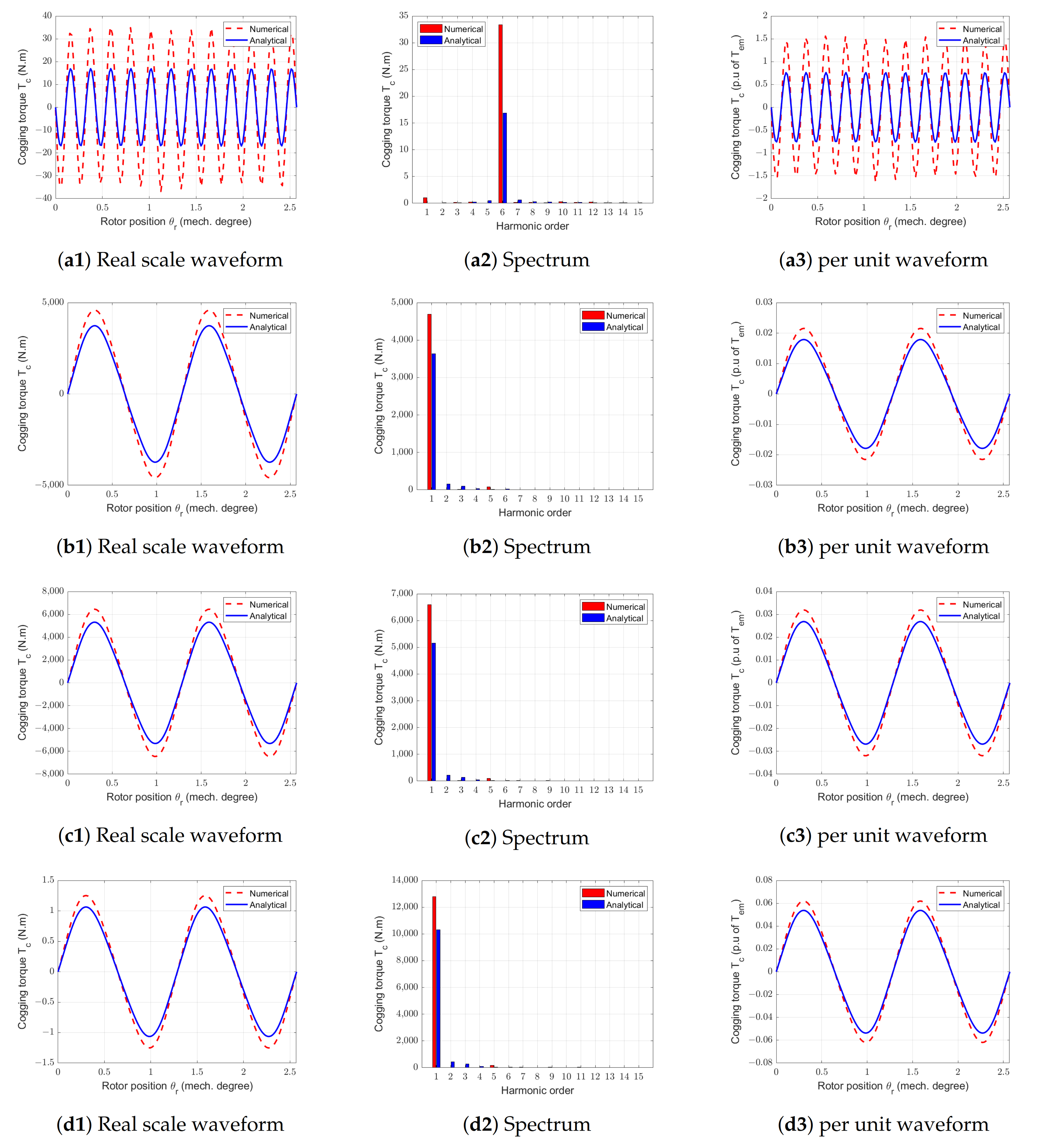
Figure 22 shows the waveforms, the spectral analysis of the cogging torques calculated by Finite Element and analytical methods, for different p g a p and n g a p values.
The choice of S p p = 2/5 leads to a very low value for the slots contribution to the cogging torque. The numerical estimation of this very small cogging torque contribution is difficult. The high relative difference between cogging torque amplitudes obtained by 2D FEM and analytical method for the reference machine can be explained by these difficulties (as shown on Figure 22(a1)).
The stator segmentation with amagnetic gaps introduces very large cogging torque contribution (Figure 10) compared to the slots contribution. Thus the amplitude of the cogging torque in the case of the stator-segmented structure is important (Figure 22b1,c1,d1).
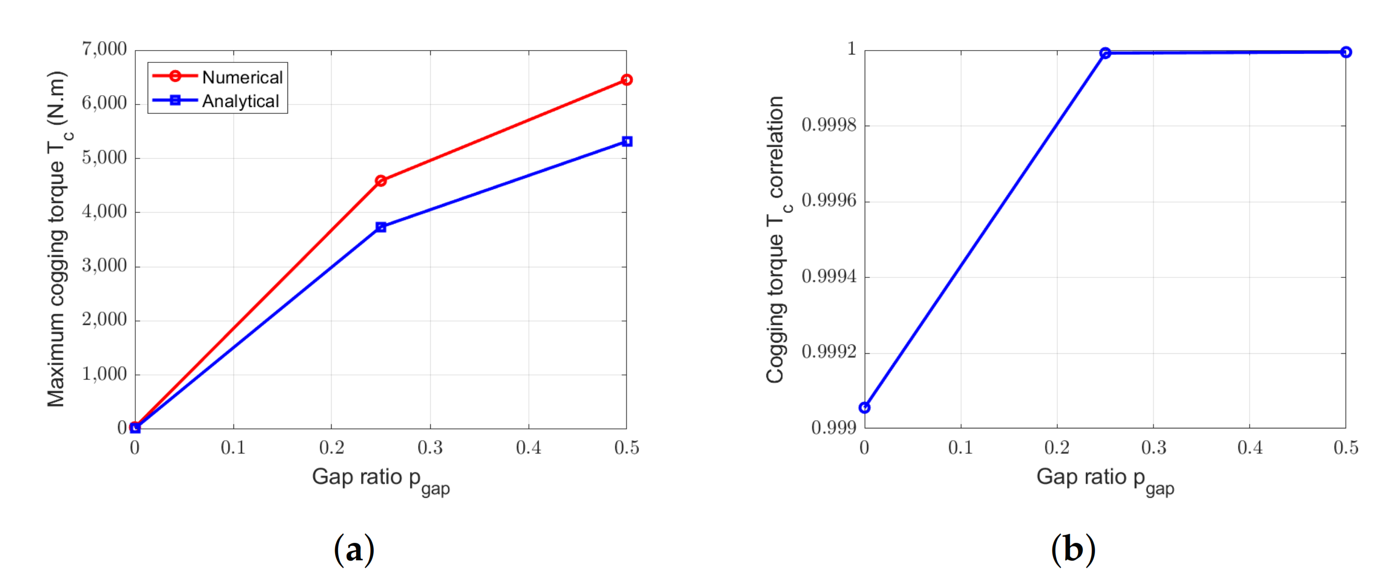
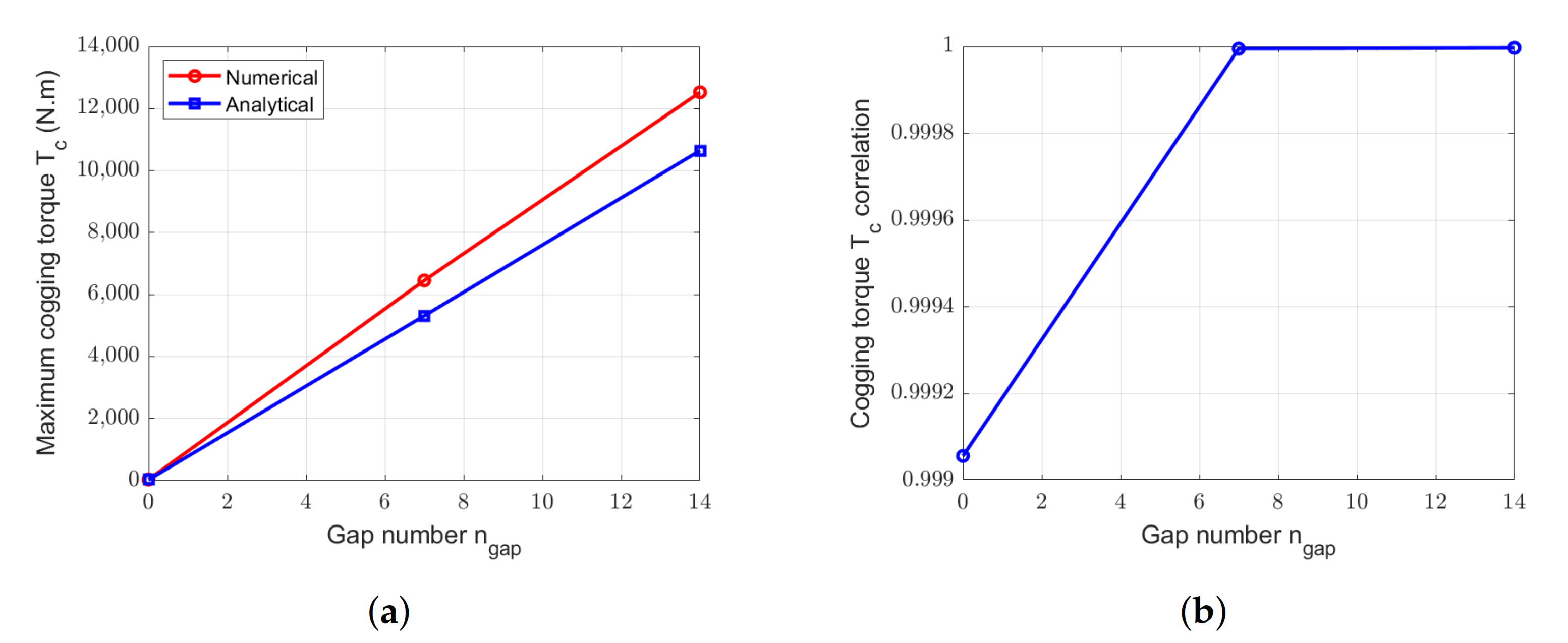
Figure 23a and Figure 24a present a comparison between the cogging torque peak values calculated by the two methods in the case of amagnetic gaps with different p g a p and n g a p values. Figure 23b and Figure 24b show the correlation values for cogging torque waveforms calculated by numerical and analytical models for the different stator gap width.
Figure 24a shows that the cogging torque related to the slots is negligible when the number of gaps increase. This is due to the low value of this cogging torque. For the studied numbers of gaps, the analytical models provide accurate estimations of the cogging torque in the case of the stator-segmented structure. The increase of n g a p allows reducing the difference between analytical and numerical results. Indeed, there is 7% of difference for seven gaps versus 4% for the 14 gaps structure.
It can be noticed that, analytical and numerical models give similar results with a difference of the amplitudes of lower than 7% for all the presented stator-segmented structures, and similar cogging torque spectrum (Figure 22(a2,b2,c2,d2)). The analytical model developed with the mono-gap method allows to well transcribe the increase of the cogging torque peak value with the raise of p g a p and n g a p . Then the mono-gap model allows determining the cogging torque of this kind of machine and can be used in a pre-design step.

4.3.2. Rotor-Segmented Case

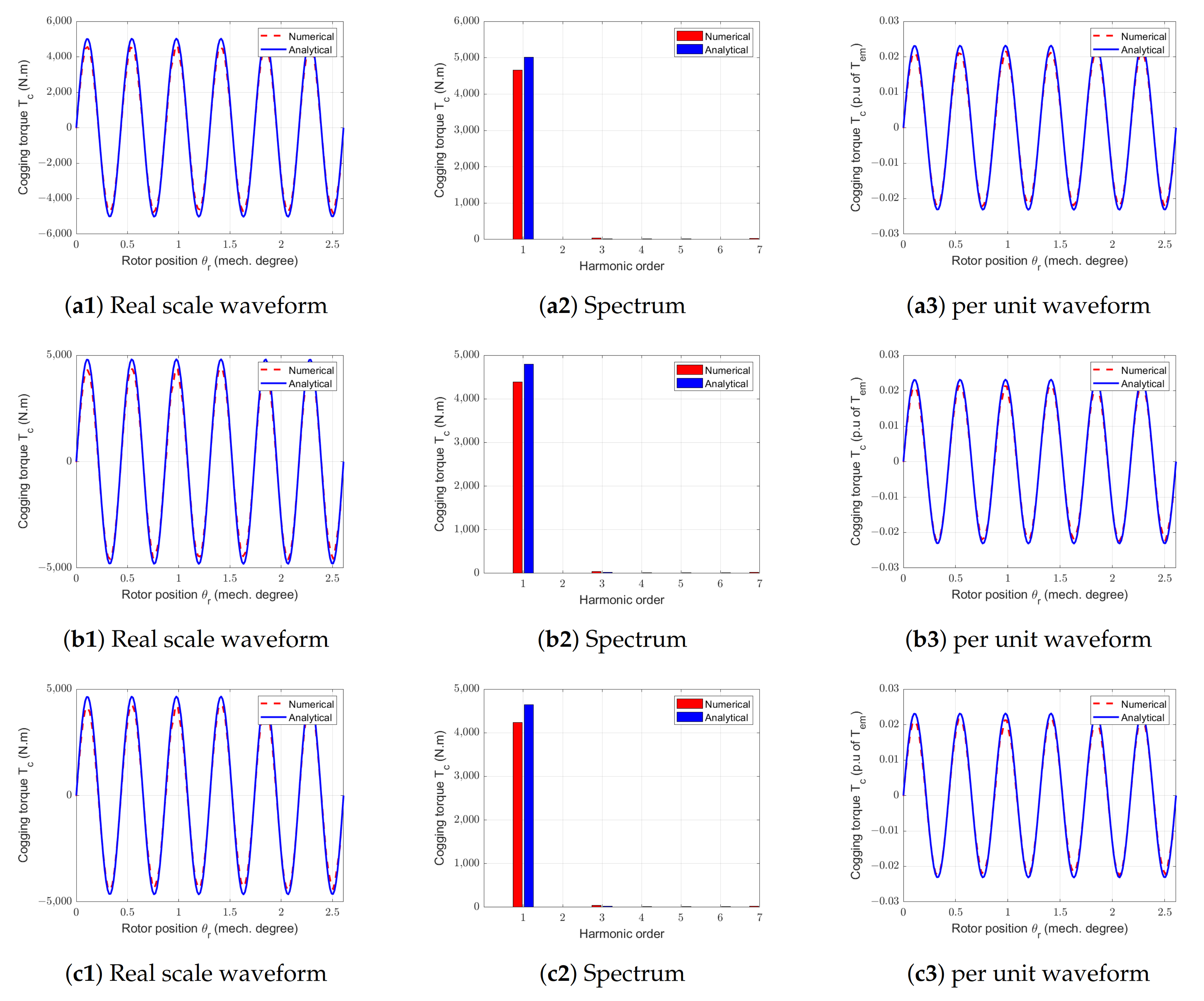
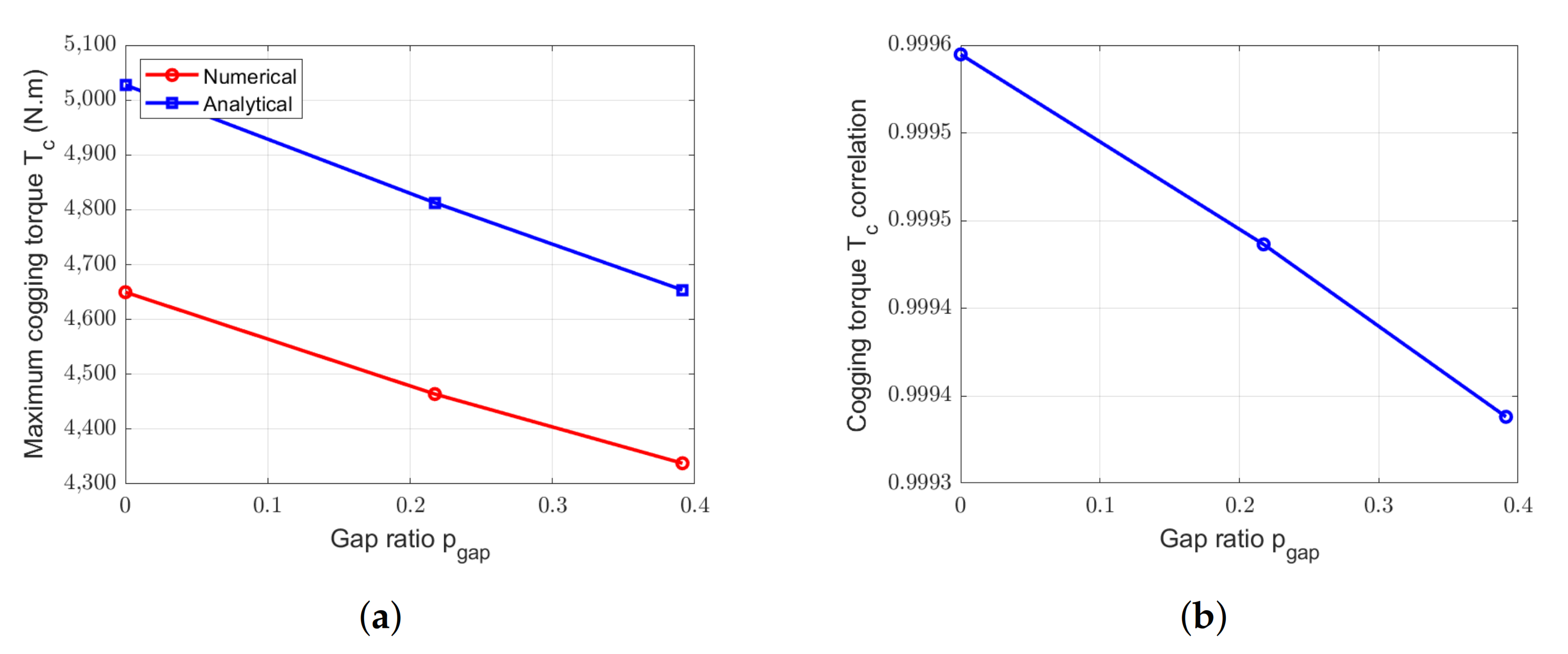
In the case of a rotor segmentation, the cogging torque amplitude is due to the stator configuration (slotting and tooth without tooth tips). In this way, the estimation of the cogging torque results from the classical method computation. Figure 25 shows the waveforms and harmonic contents for the RS-machines with different gap ratios, p g a p . In this case the peak value of the cogging torque is about 2.5 % of the rated torque of the machine. For the three presented cases the results are similar.
To validate more closely the analytical model to compute cogging torque, Figure 26 proposes to compare peak values and waveform correlation values for each cases.
The analytical estimation of the cogging torque for a rotor-segmented machine offers very good correlation results (Figure 26b) with numerical calculation. Regarding the maximum values presented in Figure 26a, analytical and numerical models lead to the same evolution in function of the gap proportion p g a p with a difference of around 7%.

4.4. Electromotive Force

The magnetic flux density is also used for the estimation of the electromotive forces. The analytical models used and validated in this section are presented on the Section 3.2.3 and Section 3.3.3.

4.4.1. Stator-Segmented Case

A no-load simulation allows to determine the electromotive forces created by the magnets on the stator windings. Figure 27 shows the comparison between EMF at 1 rd/s calculated by 2D FEM and analytical model for one of the phase (the EMF at 1 rd/s corresponds to the angular position derivative of the no-load flux in a phase using (4) and (5)).
In the case of amagnetic gaps introduced in the stator, the used analytical model leads to a very good accurate estimation of the EMF. It can be notices that only p g a p has an influence on the EMF. The results are the same for different n g a p if the gap ratio is kept constant.
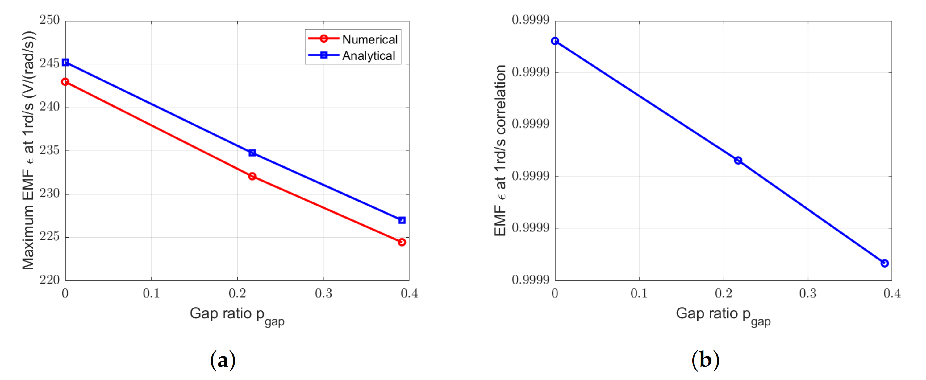
Figure 28a shows the decrease of the peak values, for both analytical and numerical methods. That decrease is due to the corrected axial length. In other words, when the correction factor is taking into account, the increase of the segmentation rate (and so the increase of the axial length) leads to a small decrease of the electromotive forces peak value. Analytical peak values of EMF is less than 1% overestimated compared to numerical results.
In term of correlation between waveforms (Figure 28b), the electromotive forces obtained by analytical and numerical methods have a correlation around 0.999 for the three p g a p values.

4.4.2. Rotor-Segmented Case

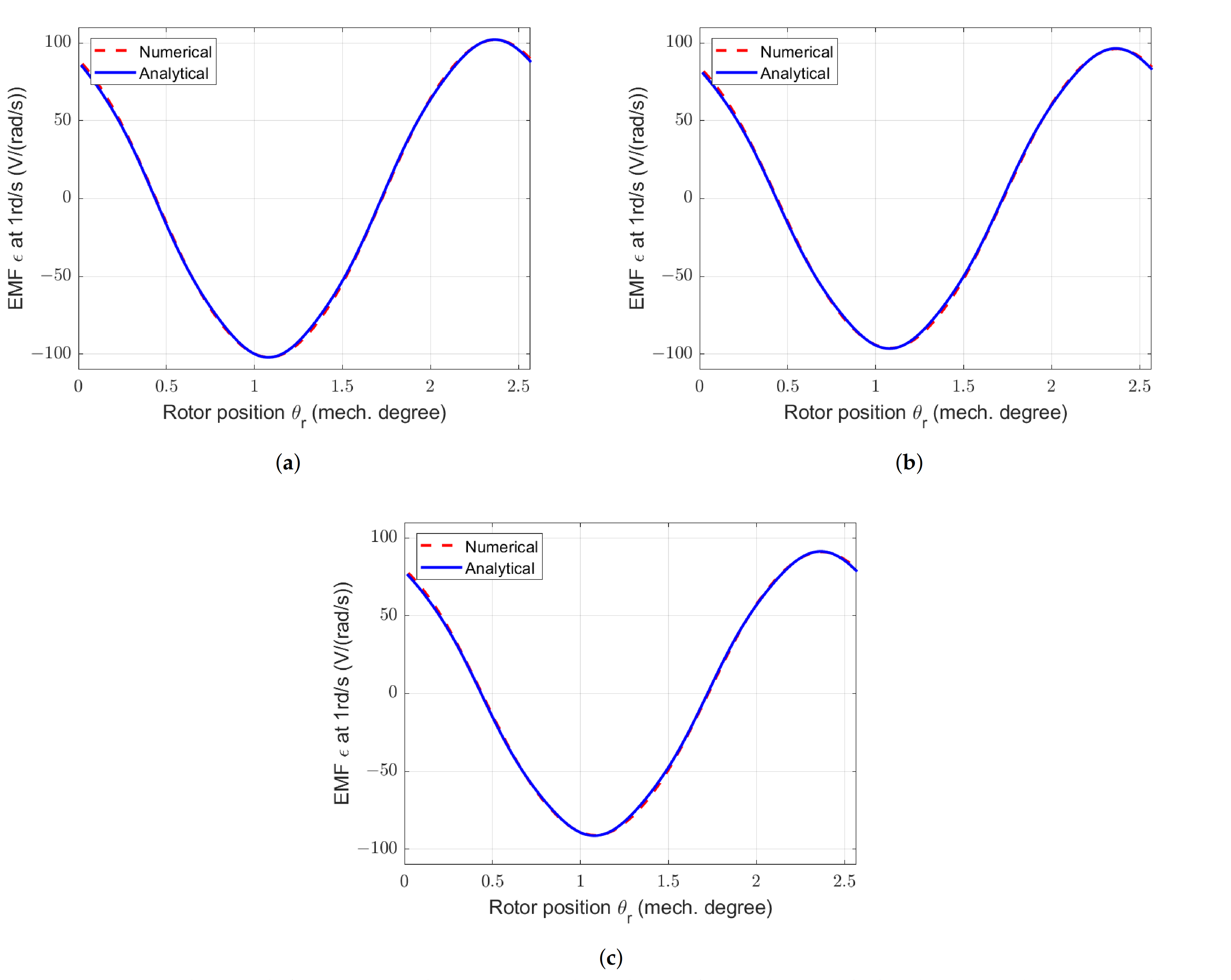
The Figure 29 presents the electromotive forces created by the magnets on the stator windings in the case of a rotor-segmented structure.
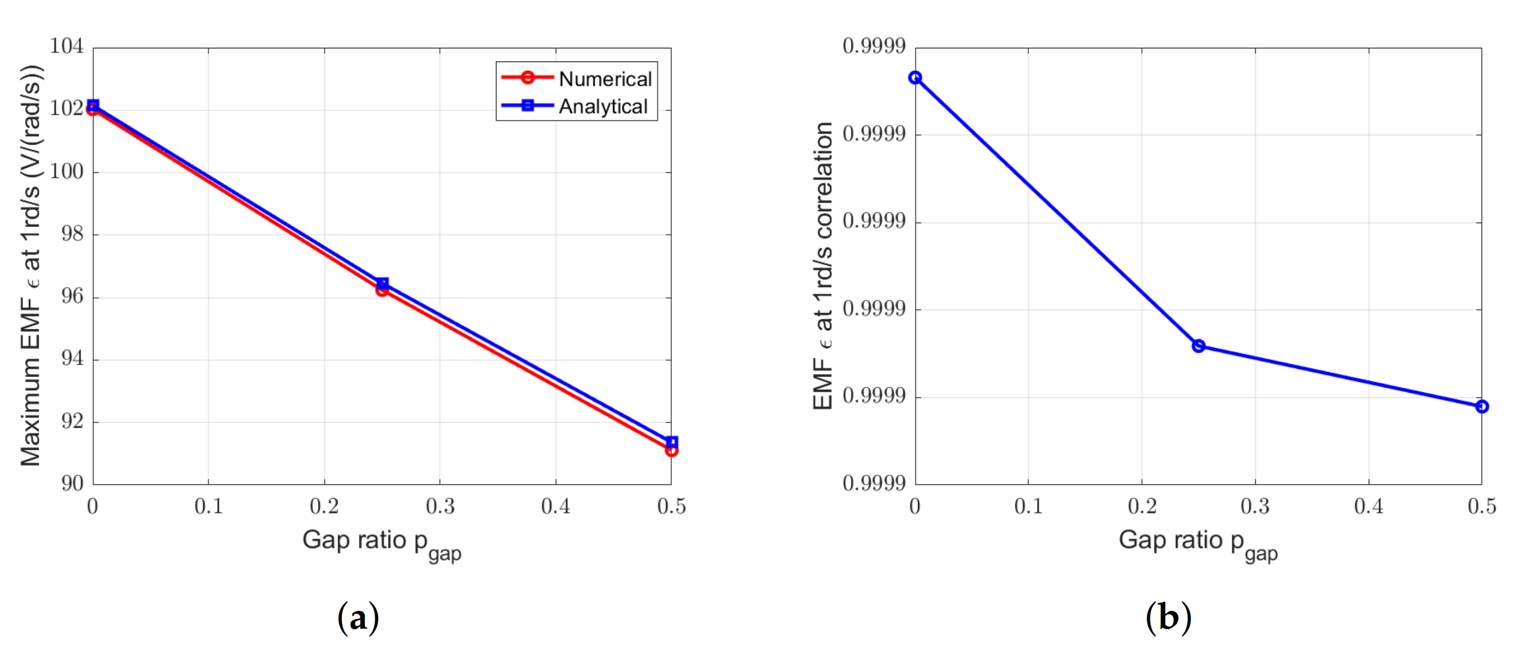
The waveforms obtained by analytical and numerical methods are very close. The Figure 30 shows a comparison between peak values from both models and the correlation value between the waveforms.
The difference between analytical and numerical peak values is less than 2%, and the correlation value is around 0.999 whatever the gap ratio (Figure 30b).
All the cases lead to good results in term of waveform correlation, peak values and change with the parameter variations.

4.5. Electromagnetic Torque

The analytical models for the estimation of the electromotive forces ares now validated and can also be used to compute the electromagnetic (EM) torque.

4.5.1. Stator-Segmented Case

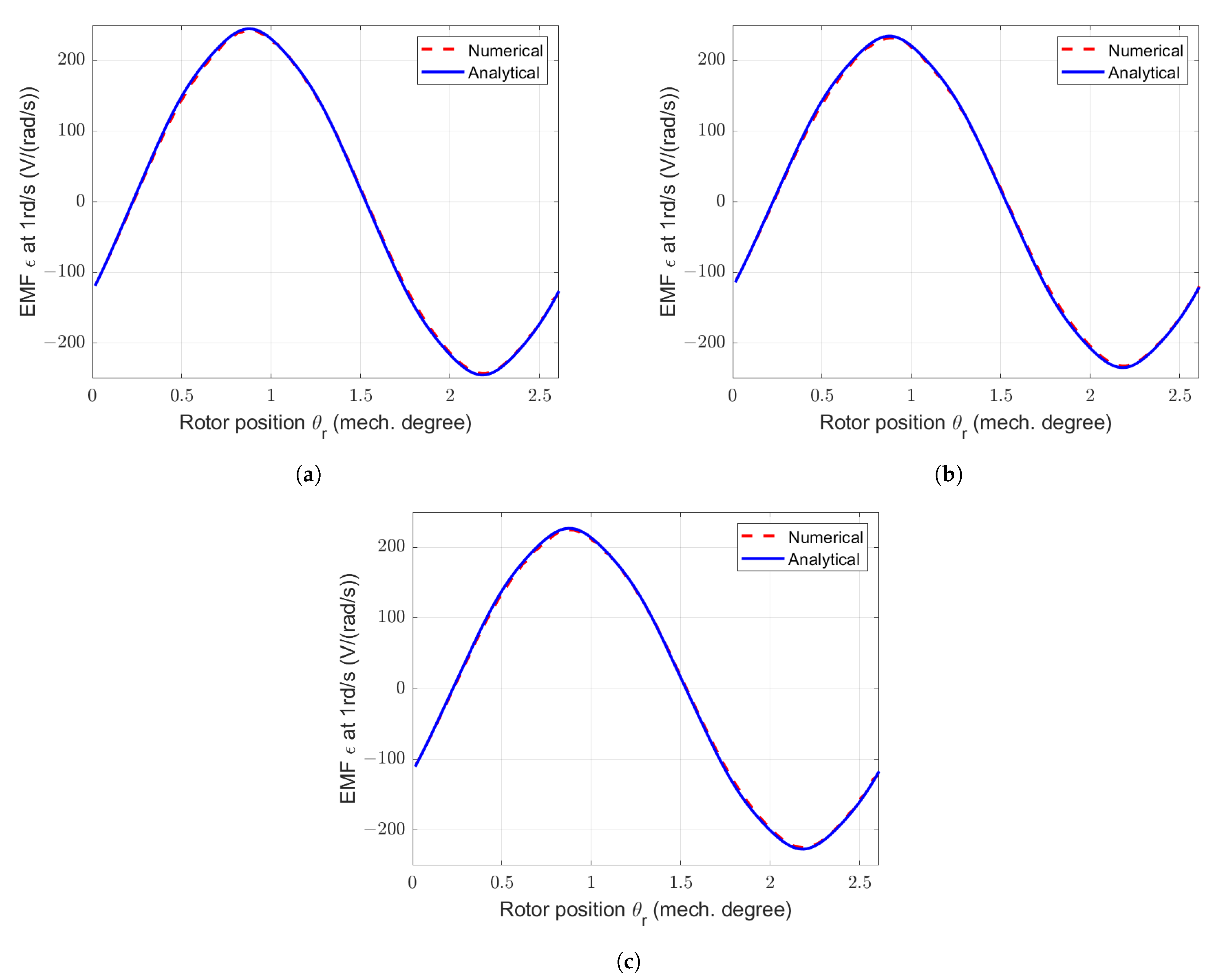
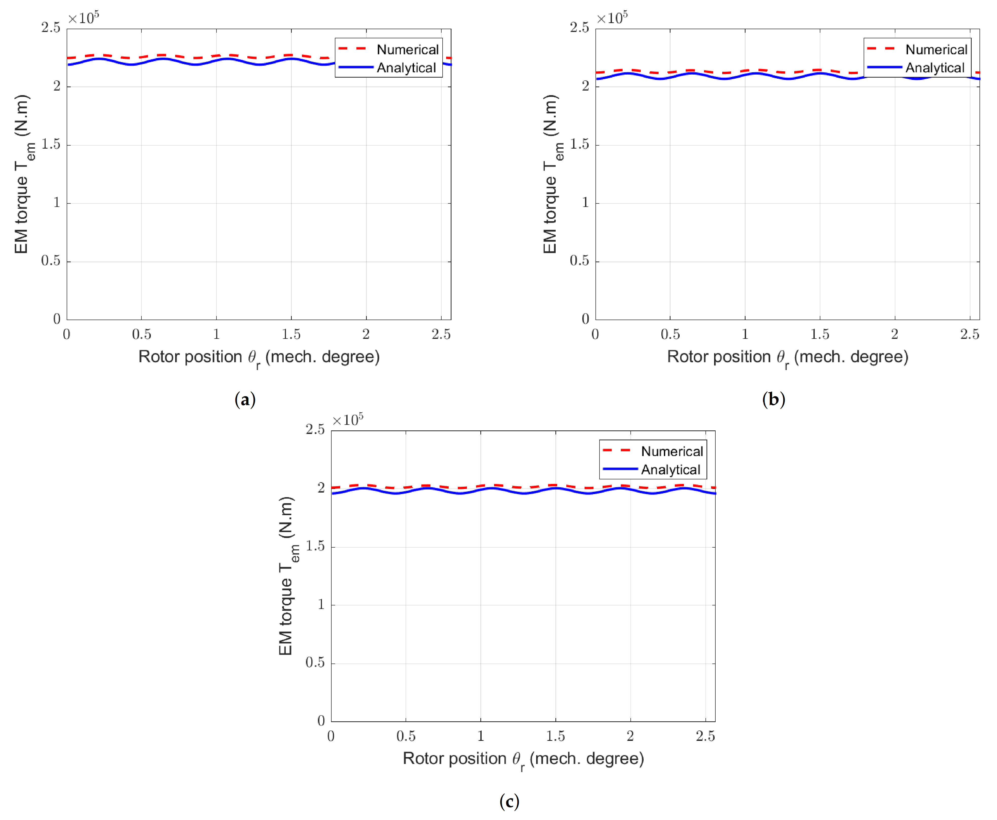
Figure 31 presents electromagnetic torques obtained using (6) from numerical and analytical models, and considering rated value sinusoidal currents.
The number of gaps does not affect the EMF calculation. So, with the same current distribution, the EM torque does not change with a variation of n g a p .
For a more precisely comparison, Figure 32a presents the comparison of the amplitude of the EM torque ripples calculated by 2D FEM and analytical models. Figure 32b presents correlations between EMF and electromagnetic torques calculated using the two methods.
Analytical models give an accurate estimation of the electromagnetic torque, compared to results from 2D FEM. The correlation value between waveforms is more than 0.999. However, the estimation of the amplitude of the ripples can be improved.
The comparison between the mean electromagnetic torques values is done in Table 5. It shows that the analytical model leads to difference less than 2% on these two quantities between numerical and analytical results.

4.5.2. Rotor-Segmented Case

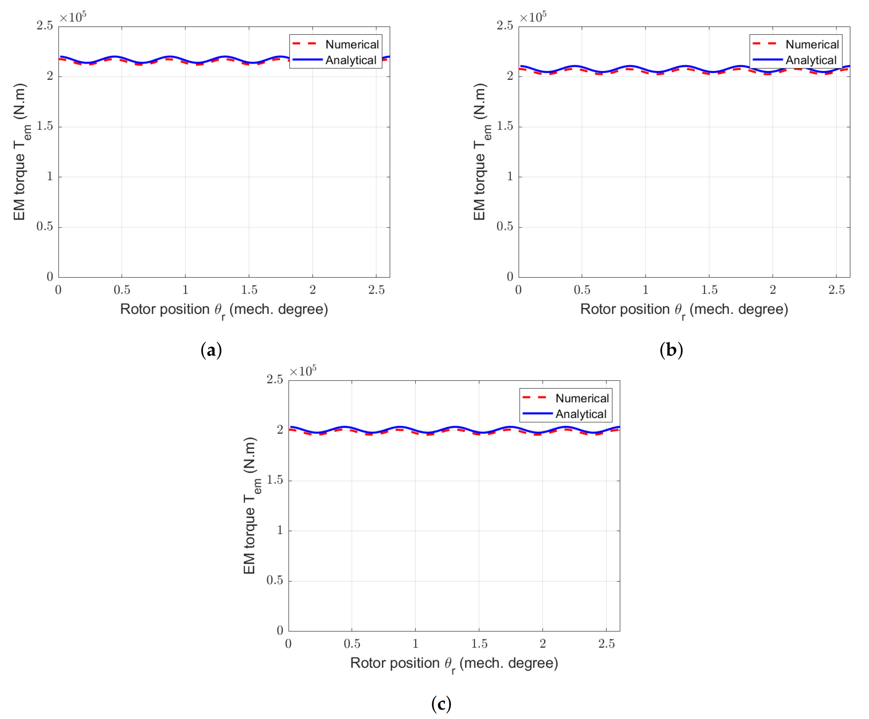
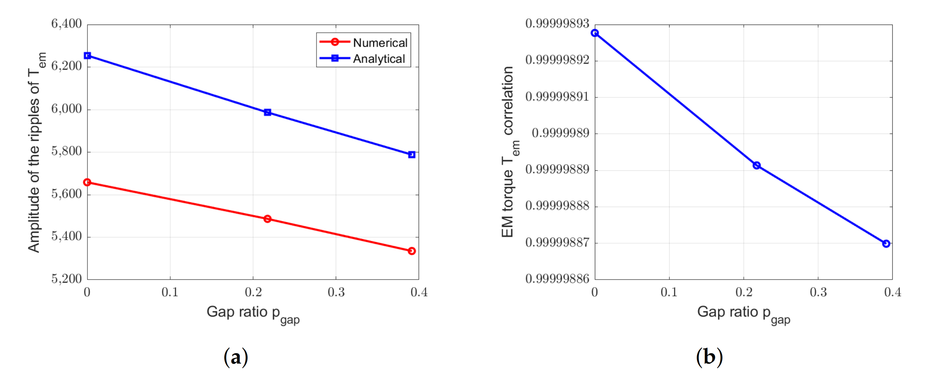
In the case of a rotor-segmented structure, Figure 33 presents the evolution of the electromagnetic torques calculated by 2D FEM and analytical models. Figure 34 shows the comparison of the amplitude of the ripples and the correlation between results obtained by both models.
The analytical model leads too to the same evolution of the amplitude of the ripples regardless to the gap ratio, and the correlation value is more than 0.999.
The analytical model allows determining also the average value of electromagnetic torque with less than 2% difference with numerical results from FluxTM 2D as shown in Table 6.

4.6. Summary

This summary corresponds to the results obtained in the case of PMSM with large diameter, large air gap length, with a large number of pairs of poles and with a magnet width to pole pitch ratio equal to 0.7. The studied segmentations are done separately on stator and rotor and contain entire pole pairs.
Table 7 presents a summary of the ratio between analytical and numerical peak values obtained for the different p g a p and n g a p .
The analytical model for the estimation of the cogging torque for the reference machine with 336 slots and 280 poles seems to doesn’t work (ratio of 0.47). This difference can be explained by the fractional slot number which leads to a very low value of cogging torque for the non-segmented structure. This very low value leads to difficulties to estimate accurately the cogging torque by FEM.

5. Conclusions

Original Permanent Magnet Synchronous Machines with segmentation of stator or rotor are considered in this study. Original models are developed to evaluate the electromagnetic performances of these machines. These models are based on adapted permeance functions which are introduced in the field density calculation to take into account the effects of the gaps. An original cogging torque calculation method is also proposed. For the cogging torque estimation, the contribution of one mono gap structure and one slotted structure are calculated independently and added. Comparison with 2D FE Method (FluxTM 2D) results in several typical test cases exhibits the accuracy of the proposed methods.
These analytical models are appropriate to evaluate the performances of PMSM with large air gap width and where entire pairs of poles are removed in the stator or in the rotor. Indeed, all the correlations between analytical and numerical results indicate less than 1% difference and mean or maximal values of electromagnetic torques are found with an error around 2%. The proposed original analytical calculation methods allows accurate and very fast calculation of the main EM characteristics of the studied unconventional electrical machines. This is why these calculation tools seems very suitable to be used for the pre-design steps or systematic design steps of such unconventional structures.

Author Contributions

Conceptualization, Methodology, E.F., F.S., J.-F.C.; software, validation, E.F.; Formal Analysis, Draft Preparation, Writing, Review, and Editing, E.F., F.S., J.-F.C. All authors have read and agreed to the published version of the manuscript.

Funding

This research received no external funding.

Acknowledgments

Numerical simulations were conducted thanks to Altair Company and the loan of a licence of the software FluxTM.

Conflicts of Interest

The authors declare no conflict of interest.

Abbreviations

The following abbreviations are used in this manuscript:
PMSMPermanent Magnet Synchronous Machine
PMpermanent magnet
FEMFinite Element Method
EMelectromagnetic
EMFelectromotive force
SS-machinestator-segmented machine
RS-machinerotor-segmented machine

References

  1. Posylek, Z. Two-dimensional cylindrical model of the sector motor with a solid rotor. Arch. Elektrotech. 1988, 71, 237–244. [Google Scholar] [CrossRef]
  2. Attaianese, C.; Del Pizzo, A.; Pagano, E.; Zaltieri, R. Brushless Sector Motors. In Proceedings of the 1993 Sixth International Conference on Electrical Machines and Drives (Conf. Publ. No. 376), Oxford, UK, 8–10 September 1993; pp. 636–640. [Google Scholar]
  3. Li, G.J.; Zhu, Z.Q.; Foster, M.; Stone, D. Comparative Studies of Modular and Unequal Tooth PM Machines either with or without Tooth Tips. IEEE Trans. Magn. 2014, 50, 10. [Google Scholar] [CrossRef]
  4. Sanada, M.; Morimoto, S.; Takeda, Y. Interior permanent magnet linear synchronous motor for high-performance drives. IEEE Trans. Ind. Appl. 1997, 33, 966–972. [Google Scholar] [CrossRef]
  5. Fleurot, E.; Charpentier, J.F.; Scuiller, F. Electromagnetic Study of Segmented Permannet Magnet Synchronous Machines for Rim-driven Applications. In Proceedings of the 19th International Symposium on Electromagnetic Fields in Mechatronics, Electrical and Electronic Engineering, Nancy, France, 29–31 August 2019. [Google Scholar]
  6. Fleurot, E.; Scuiller, F.; Charpentier, J.F. An Analytical Approach to Estimate the Cogging Torque in Segmented Stator Synchronous Permanent Magnet Machines with Large Angular Gaps. In Proceedings of the 22nd International Conference on the Computation of Electromagnetic Fields, Paris, France, 15–19 July 2019. [Google Scholar]
  7. Drouen, L.; Charpentier, J.F.; Semail, E.; Clenet, S. Study of an innovative electrical machine fitted to marine current turbines. In Proceedings of the OCEANS 2007–Europe, Aberdeen, UK, 18–21 June 2007. [Google Scholar]
  8. Krøvel, Ø.; Nilssen, R.; Skaar, S.E.; Løvli, E.; Sandøy, N. Design of an Integrated 100kW Permanent Magnet Synchronous Machine in a Prototype Thruster for Ship Propulsion. In Proceedings of the 16th International Conference on Electrical Machines, Cracow, Poland, 5–8 September 2004; pp. 117–118. [Google Scholar]
  9. Zhu, Z.Q.; Howe, D.; Bolte, E.; Ackermann, B. Instantaneous magnetic field distribution in brushless permanent magnet DC motors. I. Open-circuit field. IEEE Trans. Magn. 1993, 29, 124–135. [Google Scholar] [CrossRef]
  10. Proca, A.B.; Keyhani, A.; El-Antably, A.; Lu, W.; Dai, M. Analytical model for permanent magnet motors with surface mounted magnets. IEEE Trans. Energy Convers. 2003, 18, 386–391. [Google Scholar] [CrossRef]
  11. Zhu, Z.Q.; Ruangsinchaiwanich, S.; Howe, D. Synthesis of cogging-torque waveform from analysis of a single stator slot. IEEE Trans. Ind. Appl. 2006, 42, 650–657. [Google Scholar] [CrossRef]
  12. Amemiya, J.; Chiba, Ã.; Dorrell, D.G.; Fukao, T. Basic characteristics of a consequent-pole-type bearingless motor. IEEE Trans. Magn. 2005, 41, 82–89. [Google Scholar] [CrossRef] [Green Version]
  13. Cheng, M.; Wen, H.; Han, P.; Zhu, X. Analysis of Airgap Field Modulation Principle of Simple Salient Poles. IEEE Trans. Ind. Electron. 2019, 66, 2628–2638. [Google Scholar] [CrossRef]
  14. Cros, J.; Viarouge, P. Synthesis of high performance PM motors with concentrated windings. IEEE Trans. Energy Convers. 2002, 17, 248–253. [Google Scholar] [CrossRef]
  15. Djebarri, S.; Charpentier, J.F.; Scuiller, F.; Benbouzid, M. Design and Performance Analysis of Double Stator Axial Flux PM Generator for Rim Driven Marine Current Turbines. IEEE J. Ocean. Eng. 2016, 41, 50–66. [Google Scholar]
  16. Bechrakis, D.A.; Sparis, P.D.; Fukao, T. Correlation of wind speed between neighboring measuring stations. IEEE Trans. Energy Convers. 2004, 19, 400–406. [Google Scholar] [CrossRef]
Figure 1. Structures of permanent magnet synchronous machines with (a) stator and (b) rotor segmentations.
Applsci 11 00459 g001
Figure 2. Stator-segmented structure.
Applsci 11 00459 g002
Figure 3. Magnetic circuits of the studied machines: (a) non-segmented machine, (b) stator-segmented machine with amagnetic gaps, (c) rotor-segmented machine with amagnetic gaps.
Applsci 11 00459 g003
Figure 4. Flux lines in a slot opening for a radial magnetization.
Applsci 11 00459 g004
Figure 5. Permeance function taking into account the slot openings for a non-segmented machine.
Applsci 11 00459 g005
Figure 6. Areas used for the calculation of the cogging torque.
Applsci 11 00459 g006
Figure 7. Permeance function (relative value) for the machine under consideration with stator segmentation by an amagnetic material (336 slots, 140 pole pairs, 7 gaps, and 25% of gap).
Applsci 11 00459 g007
Figure 8. Analytical evaluation of the ratio between the magnetic flux density of a machine with an infinite air gap and of a slotless machine.
Applsci 11 00459 g008
Figure 9. Magnetic circuit of the two basics structures. (a) Slotted machine. (b) Mono-gap machine.
Applsci 11 00459 g009
Figure 10. Cogging torque for two mono-gap widths estimated by numerical method (FEM).
Applsci 11 00459 g010
Figure 11. Cogging torques obtained by numerical and analytical models for a machine with only one gap of ten-pole pitches.
Applsci 11 00459 g011
Figure 12. Modulation function to take into account the parts without magnet for a structure with p g a p around 20% and n g a p = 6 gaps.
Applsci 11 00459 g012
Figure 13. Representation of the geometric parameters.
Applsci 11 00459 g013
Figure 14. Axial length depending on the proportion of segmentation, with and without considering the 3D correction, for the machines (a) with S p p = 2 / 5 and (b) with S p p = 1 / 2 .
Applsci 11 00459 g014
Figure 15. Studied machines. (a) Non-segmented machine with S p p = 2/5. (b) Stator-segmented machine with 25% of amagnetic gap. (c) Non-segmented machine with S p p = 1/2. (d) Rotor-segmented machine with around 20% of amagnetic gap.
Applsci 11 00459 g015
Figure 16. Permeance function for the SS-machine with p g a p = 0.50. (a) n g a p = 7 gaps. (b) n g a p = 14 gaps.
Applsci 11 00459 g016
Figure 17. Waveforms and spectral analysis of magnetic flux density for the SS-machine with different pgap and ngap (a1,a2) Reference machine. (b1,b2) SS-machine with pgap = 0.25 and ngap = 7 gaps. (c1,c2) SS-machine with pgap = 0.50 and ngap = 7 gaps. (d1,d2) SS-machine with pgap = 0.50 and ngap = 14 gaps.
Applsci 11 00459 g017
Figure 18. Comparison between numerical and analytical calculation of magnetic flux densities due to PM for the SS-machine with n g a p = 7 gaps and with different p g a p . (a) Peak values. (b) Correlation.
Applsci 11 00459 g018
Figure 19. Comparison between numerical and analytical calculation of magnetic flux densities due to PM for the SS-machine with p g a p = 0.50 and with different n g a p . (a) Peak values. (b) Correlation.
Applsci 11 00459 g019
Figure 20. Waveforms and spectral analysis of magnetic flux density for the RS-machine with different pgap and ngap = 6 gaps. (a1,a2) Reference machine. (b1,b2) RS-machine with pgap = 0.217. (c1,c2) RS-machine with pgap = 0.391.
Applsci 11 00459 g020
Figure 21. Comparison between numerical and analytical calculation of magnetic flux densities due to PM for the RS-machine with n g a p = 6 gaps and with different p g a p . (a) Peak values. (b) Correlation.
Applsci 11 00459 g021
Figure 22. Waveforms and spectral analysis of cogging torques for the SS-machine with different pgap and ngap. (a1a3) Reference machine. (b1b3) SS-machine with pgap = 0.25 and ngap = 7 gaps. (c1c3) SS-machine with pgap = 0.50 and ngap = 7 gaps. (d1d3) SS-machine with pgap = 0.50 and ngap = 14 gaps.
Applsci 11 00459 g022
Figure 23. Comparison between numerical and analytical calculation of cogging torque for the SS-machine with n g a p = 7 gaps and with different p g a p . (a) Peak values. (b) Correlation.
Applsci 11 00459 g023
Figure 24. Comparison between numerical and analytical calculation of cogging torque for the SS-machine with p g a p = 0.50 and with different n g a p . (a) Peak values. (b) Correlation.
Applsci 11 00459 g024
Figure 25. Waveforms and spectral analysis of cogging tprques for the RS-machine with different pgap and ngap = 6 gaps. (a1a3) Reference machine. (b1b3) pgap = 0.217. (c1c3) pgap = 0.391.
Applsci 11 00459 g025
Figure 26. Comparison between numerical and analytical calculation of cogging torque for the RS-machine with n g a p = 6 gaps and with different p g a p . (a) Peak values. (b) Correlation.
Applsci 11 00459 g026
Figure 27. Waveforms of electromotive forces in one phase (neutral phase) at 1rd/s for the SS-machine with different p g a p . (a) Reference machine. (b) SS-machine with p g a p = 0.25 and n g a p = 7 gaps. (c) SS-machine with p g a p = 0.50 and n g a p = 7 gaps.
Applsci 11 00459 g027
Figure 28. Comparison between electromotive forces obtained by numerical and analytical methods in one phase at 1 rd/s for the SS-machine with n g a p = 7 gaps and with different p g a p . (a) Peak values. (b) Correlation.
Applsci 11 00459 g028
Figure 29. Calculated waveforms of electromotive forces at 1 rd/s for the RS-machine with different p g a p . (a) Reference machine. (b) RS-machine with p g a p = 0.217 and n g a p = 7 gaps. (c) RS-machine with p g a p = 0.391 and n g a p = 6 gaps.
Applsci 11 00459 g029
Figure 30. Comparison between EMF obtained by numerical and analytical methods at 1 rd/s for the RS-machine with n g a p = 6 gaps and with different p g a p . (a) Peak values. (b) Correlation.
Applsci 11 00459 g030
Figure 31. Waveforms of EM torques for the SS-machine with different p g a p . (a) Reference machine. (b) SS-machine with p g a p = 0.25 and n g a p = 7 gaps. (c) SS-machine with p g a p = 0.50 and n g a p = 7 gaps.
Applsci 11 00459 g031
Figure 32. Comparison between EM torques obtained by numerical and analytical methods for the SS-machine with n g a p = 7 gaps and with different p g a p . (a) Amplitude of the ripples. (b) Correlation.
Applsci 11 00459 g032
Figure 33. Waveforms of EM torques for the RS-machine with different p g a p . (a) Reference machine. (b) RS-machine with p g a p = 0.217 and n g a p = 7 gaps. (c) RS-machine with p g a p = 0.391 and n g a p = 6 gaps.
Applsci 11 00459 g033
Figure 34. Comparison between EM torques obtained by numerical and analytical methods for the RS-machine with n g a p =6 and with different p g a p . (a) Amplitude of the ripples. (b) Correlation.
Applsci 11 00459 g034
Table 1. Main parameters of Rim-Driven machine (derived from [7]).
Power P (kW)300
Turbine speed N (rpm)15
Air gap length h g (m)0.02
Linear electric loading A L (kA×m 1 )60
Current density J (A×mm 2 )4
Magnet width ( τ m ) to pole pitch ( τ p ) ratio β m 0.7
Stator internal diameter D (m)11.151
Magnet remanence B r (T)1.2
Magnet relative permeability μ r 1.05
Table 2. Main geometric parameters of reference machine designed to the rotor segmentation.
Number of slots per pole and per phase S p p 1/2
1st harmonic winding coefficient k w 0.866 [14]
Pole pair angular width (rad)2 π /138
Magnet height h m (m)0.0208
Slot depth h s (m)0.0434
Tooth to slot pitch ratio β t 0.54
Stator and rotor yoke height hy (m)0.0236
Iron axial length Lz0 (m)0.0564
Table 3. Main geometric parameters of reference machine designed to the stator segmentation.
Number of slots per pole and per phase S p p 2/5
1st harmonic winding coefficient k w 0.966 [14]
Pole pair angular width (rad)2 π /140
Magnet height h m (m)0.0210
Slot depth h s (m)0.0472
Tooth to slot pitch ratio β t 0.58
Stator and rotor yoke height h y (m)0.0248
Iron axial length L z 0 (m)0.0518
Table 4. Test case topology for the parametric variations.
Q s pSegmented Part p gap n gap
336140none00
336140stator0.257
336140stator0.507
336140stator0.5014
414138none00
414138rotor0.2176
414138rotor0.3916
Table 5. Evolution of the mean electromagnetic torques for the SS-machine with n g a p = 7 gaps.
Gap Proportion0%25%50%
Numerical T e m ( kN × m ) 226213213
Analytical T e m ( kN × m ) 222209209
Ratio (%)98.298.198.1
Table 6. Evolution of the mean electromagnetic torques for the RS-machine with n g a p = 6 gaps.
Gap Proportion0%~20%~40%
Numerical T e m ( kN × m ) 215205198
Analytical T e m ( kN × m ) 217208201
Ratio (%)99.198.698.5
Table 7. Ratio between analytical and numerical value calculated for the studied EM quantities.
Q s pSegmented Part p gap n gap Maximum B / R Maximum C d Maximum EMF
336140none000.930.471.00
336140stator0.2570.920.921.00
336140stator0.5070.920.931.00
336140stator0.50140.930.961.01
414138none000.930.921.0
414138rotor0.21760.910.931.01
414138rotor0.39160.910.931.01
Publisher’s Note: MDPI stays neutral with regard to jurisdictional claims in published maps and institutional affiliations.