Article

Static Lateral Stability of Tractor with Rear Wheel Ballast Weights: Comparison of ISO 16231-2 (2015) with Experimental Data Regarding Tyre Deformation

1
Department of Transport and Handling, Faculty of Engineering, Slovak University of Agriculture in Nitra, Tr. A. Hlinku 2, 949 76 Nitra, Slovakia
2
Department of Quality and Engineering Technologies, Faculty of Engineering, Slovak University of Agriculture in Nitra, Tr. A. Hlinku 2, 949 76 Nitra, Slovakia
3
Department of Statistics and Operations Research, Faculty of Economics and Management, Slovak University of Agriculture in Nitra, Tr. A. Hlinku 2, 949 76 Nitra, Slovakia
4
Information and Coordination Centre of Research, Faculty of Engineering, Slovak University of Agriculture in Nitra, Tr. A. Hlinku 2, 949 76 Nitra, Slovakia
5
Department of Agricultural, Food and Environmental Engineering, Faculty of Agri Sciences, Mendel University in Brno, Zemědělská 1665/1, 613 00 Brno, Czech Republic
*
Author to whom correspondence should be addressed.
Appl. Sci. 2021, 11(1), 381; https://doi.org/10.3390/app11010381
Submission received: 10 December 2020 / Revised: 26 December 2020 / Accepted: 29 December 2020 / Published: 2 January 2021

Abstract

:
The paper presents a static lateral stability of a sub-compact tractor MT8-070 Mini in relation to a safe tractor operation. Axle weight distribution of the tractor was measured to calculate the vertical and longitudinal coordinates of a centre of gravity (COG). Experiments were aimed at the tractor equipped with no and four levels of rear wheel ballast weights (30.5, 61, 91.5 and 122 kg) at standard and extended overall width on tyres. A static overturning angle was calculated and experimentally measured when the tractor with right wheels touching the ground was in a state of unstable equilibrium. Comparing the experimental data with ISO 16231-2 (2015), the differences were 2.57%, 2.80%, 3.04%, 3.42% and 3.88% in the case of the standard overall width on tyres and 2.40%, 2.61%, 3.11%, 3.67% and 3.99% in the case of the extended overall width on tyres at 0, 30.5, 91.5 and 122 kg of the rear wheel ballast weight. Considering the vertical tyre deformation and the lateral shift of the tyre, the differences decreased to 0.95%, 1.11%, 1.29%, 1.85% and 1.42% (standard overall width on tyres) and 0.91%, 1.18%, 1.69%, 2.27% and 2.57% (extended overall width on tyres). The length of a rubber lug of a tyre contact patch did not change when the tractor was inclined at various ballast weights and did not affect the static overturning angle calculation according to ISO 16231-2 (2015). Results showed higher static overturning angle experimentally measured in comparison with calculated according to ISO 16231-2 (2015) due to the tyre deformation. Limiting the tractor operation on the basis of the static overturning angle calculated according to ISO 16231-2 (2015) avoids the tractor usage under dangerous operation conditions.

1. Introduction

Tractor overturning is a dangerous accident, by which a tractor operator is endangered and tractor damaged. Improvements in the design of tractors cannot fully eliminate the risk of these accidents. A constantly increasing demand for agricultural products has also led to cultivation of areas that are non-ideal for mechanization due to geo-orographic conformation of the land, particularly due to very steep, sloping grounds, albeit with interesting agronomic characteristics in terms of climate and solar radiation [1]. Tractor overturning remains a serious problem in agricultural activities. A detailed analysis of problems and causes leading to a tractor overturn have revealed that by improving tractor’s static stability we can positively influence the safety as early as during the concept phase [2]. Overturning accidents cost time and money as well as causing injury and sometimes death. A full understanding of stability on slopes is needed in order to establish safe operating limits which can be accepted throughout the land-based industries [3]. Agricultural tractors as manufactured are characterised by high rates of standardisation and feature a range of additional attachments which allow a wider use of each tractor and greatly facilitate its operation [4]. The need for tractors and agricultural machinery to be tested from the point of view of their suitability for agricultural use will grow continuously because these machines directly affect agricultural production [5].
An extreme variety of situations that an agricultural machine can meet does not find an adequate match with the test situations actually proposed by standards. Indeed, although all real situations must be necessarily simplified and standardized to be investigated experimentally, the tests that are currently adopted to inquire a rollover stability of machines, although simple and effective in their way of operating, have many basic deficiencies [6]. Standards require main measures to eliminate the errors negatively affecting the results of calculation methodologies [7]. An elimination of the errors during the measurements of the parameters needed for calculation of the static overturning angle improves the results of the calculation model. Defining the tractor lateral stability, the calculation of the static overturning angle is based on the technical parameters of the tractor and the coordinates of COG [8]. The calculation methodology uses the location of COG in relation to the stability triangle. [9] presented that the dimensions of the vehicle such as: wheelbase, overall width on the tyres and weight distribution between axles are the main factors that affect the tractor stability.
The next factor affecting the tractor stability is the tyre deformation which depends on the different elastic properties and weight acting on the wheel. The tyre deformation affects the tractor dimensions and COG coordinate used for calculation of the static overturning angle. When the tractor is inclined, the shift of the centre of gravity affects the static overturning angle and the tractor lateral stability. Many authors of papers aimed at the tractor stability presented that the effect of shifting the centre of gravity is small in comparison to the tractor dimensions which essentially affect the tractor lateral stability [10]. The next important effect of the tyre deformation is the lateral tyre shift formed by tractor weight. It reduces the stability of the tractor. If other moments act in the same direction and are large, the tractor might overturn. To evaluate this influence, the sidewall deflection rates must be known [11].
Lateral overturning of agricultural tractors is a very dangerous accident. The objectives of this study were (a) to compare the static overturning angle calculated according to standard [12] with experimental data using the sub-compact agricultural tractor with rear wheel ballast weights at standard and extended overall width on tyres, (b) to analyse the influence of a vertical tyre deformation, a lateral shift of the tyre and dimensions of a tyre contact patch changed due to tyre deformation (when the tractor was tilted) on the calculation of the static overturning angle, (c) to analyse the factors affecting the tractor lateral stability in relation to safe tractor operation.

2. Materials and Methods

2.1. Experimental Tractor and Measurement Procedure

The experiments were performed with a sub-compact tractor MT8-070 Mini (Agrozet a. s., České Budějovice, Czech Republic) equipped with a petrol four-stroke air-cooled (Briggs and Stratton) engine. The experimental tractor with rear-wheel drive has the transmission with four forward gears and one reverse gear. It is equipped with a differential lock and hydraulic system with manually driven piston hydraulic pump. Detailed properties of this tractor were presented by [13,14,15]. Rear wheels (fixed axle) were equipped with the Mitas TS-02, 6.5/75-14 tyres, (Mitas a. s., Prague, Czech Republic), and front wheels (swivelling axle) with the Barum Industrie NB 44, 4.00-8 tyre (Barum a. s., Otrokovice, Czech Republic). The basic technical specifications of the experimental tractor are listed in Table 1.
To simulate the real operation conditions of the tractor, a driver seat was loaded with a ballast weight of 75 kg corresponding with the average human body weight. [16] presents that the COG of a human body lies in the area of the 3rd to 4th sacral vertebra. The ballast weight of three sandbags (the weight of one sandbag is 25 kg) equals to 75 kg and they were fixed to the tractor driver seat by the tension belt ratchet lashing strap, Figure 1. The height of three sandbags placed at each other is 45 cm, then we consider the COG in the same position as in the human body.
Standards [12] and [17] specify the method to determine the centre of gravity (COG) of self-propelled machines. The standard recommends several measures to eliminate the measurement errors caused by various factors. To determine the COG coordinates, these measures were considered during the measurements. The measurements were performed on a horizontal surface of the flat laboratory floor. The measurements were performed using the scales (wheel weighting pads) and support crane (Figure 2). Two weighting pads were placed under both wheels of the rear axle. The height of the weighting pad was 0.058 m. To provide the horizontal (level) position of the tractor, wood pads (the same height as the weighting pads) were placed below the wheels of the other axle. In the next step, the mass on both wheels on the left and right side of the tractor were measured to state a lateral position of COG. The exact mass of the rear wheel ballast weight (steel discs) was measured as shown in Figure 2c). When the front axle (swivelling axle) was lifted, the rear wheels on the scales were free to rotate (brakes were not applied, and the transmission was in neutral). To eliminate the measurement errors caused by the tyre deflection, standard [12] recommends increasing the tyre inflation pressure to the maximum permissible value. All tyres were inflated to the maximum pressure of 150 kPa recommended by manufacturer. In the fuel tank, the liquid moves and changes the COG location of the tractor. To eliminate the measurement error due to liquid shift, the fuel tank was full of gasoline (recommendation of [12]).
Standard [12] allows to use various techniques to tilt the tractor with or without all tractor wheels on a tilting platform (point 5.7 in the standard). [19] used a tilting platform to test the lateral overturning of the tractor. In this case, all tractor wheels are placed on the platform. [20] tilted the tractor, using a tilting platform, to determine the angle at the moment when the tractors were resting in a state of unstable equilibrium on the wheels touching the ground. [21] laterally tilted the tractor by elevating the right wheels with a forklift until the unstable equilibrium position was reached. Following the standard and authors mentioned above, the tilting platform (Figure 3) was used to measure the lateral stability of the tractor on the basis of static overturning angle α. The tractor was tilted up to a state of unstable equilibrium on the wheels touching the ground. In this state, the wheels on the opposite side of the tractor lose contact with the tilting platform when it reaches the static overturning angle. When the tractor reaches the unstable equilibrium point, it returns to the horizontal position.
The wheel weighting pads WWSE 10 T with a weight indicator (Dini Argeo, Spezzano di Fiorano Modenese, Italy) were used to measure the mass of the tractor coming on the tractor wheels (Figure 2). The rated capacity of the weighting system is 10,000 kg. The mass of the tractor is significantly lower than the rated capacity of the weighting system. Therefore, the weighting system was calibrated by an accredited laboratory (Brutto s.r.o., Sereď, Slovak Republic) to the rated capacity of 400 kg with a measuring error of 0.125% and resolution of 0.5 kg. To calculate the longitudinal and the vertical coordinates of the COG, distances were measured by a measuring tape with measuring range of 2 m, accuracy class 2 and resolution of 1 mm. Distances needed for calculation of the tyre deformation were measured with a digital calliper CD-15CP (Mitutoyo corporation, Tokyo, Japan) with a range of 0–150 mm, accuracy of ±0.02 mm and digital step of 0.01 mm. Vertical planes needed for distance measurements were determined using a steel set square and a plumb line. A digital protractor Genborx 810–100 (Changzhou Skyvictor Ltd., Changzhou, China) with measuring range 4 × 90°, display resolution 0.1° and accuracy error 0.01° was used to measure the static overturning angle when the tractor was tilted. All experimental measurements were repeated three times and the mean value with standard deviation was calculated. The regression analysis (Microsoft Excel—Office 365) was used to analyse the effect of the rear wheel ballast weight on the coordinates of COG (longitudinal and vertical), the static overturning angle and the parameters defining the tyre deformation (the vertical tyre deformation, the lateral shift of the tyre, dimensions of the tyre contact patch) at the standard and the extended overall width on tyres. The experiments were performed at standard and extended overall width on tyres of the fixed axle at 0, 30.5, 61, 91.5 and 122 kg of the rear wheel ballast weights. Four levels of rear wheel ballast weight were set with eight original steel discs connected with tractor wheels by three screws. Mass of one steel disc of 15.25 kg was measured by the weighting pads WWSE 10 T, Figure 2c.

2.2. Calculation of Static Overturning Angle According to ISO 16231-2

The standard [12] presents a method for calculation of the static overturning angle of the tractor with one swivelling axle without swivelling angle limiting device and pivot point of swivelling axle in line with the centre line of the tractor, Figure 4. The standard defines the rolling line of the tyres on the fixed axle (when rolling laterally) at 75% of the tyre width. Abscissa AA′ is the base line of stability triangle and is calculated according to the formula as follows:
A A = o 2 ( p 0.75 p ) 2
where: AA′—base line of stability triangle, m; o—overall width on tyres of the fixed axle, m; p—width of tyres on fixed axle, m
Considering the calculation method according to standard [12], the static overturning angle is the arc tangent of slope line DF over the vertical coordinate of COG h.

2.3. Evaluation of Tyre Deformation

The influence of tyre deformation on the difference between the static overturning angle calculated according to standard [12] and experimental data was analysed. This study was aimed at the tyre deformation when the tractor was tilted under experimental conditions. The effect of tyre deformation on the measurements of COG coordinate was not evaluated.
The tyre deforms when the weight acting on the wheel and the static overturning angle increase. The influence of the tyre deformation on the static overturning angle was analysed on the basis of:
  • Vertical tyre deformation affecting the vertical shift of the COG;
  • Tyres shift due to lateral tyre deformation and contact patch affecting the overall width on tyres.
The experimental tractor with various levels of rear wheel ballast weights at standard and extended overall width on tyres was inclined at the experimental static overturning angle to measure the parameters for the tyre deformation analysis. [22] presented that the deflection of the tyres (elastic elements supporting the tractor itself) can cause a translation of the COG and/or an additional pitch and roll angle. The authors complexly researched the COG translation due to the tyre deformation of the upstream and downstream wheels when the tractor was inclined at various angles. We evaluated the tractor in the state of the unstable equilibrium. In this state, we considered the effect of upstream wheel deformation on the COG position as negligible, and we considered only the effect of the vertical tyre deformation on the vertical position of COG.
In the first, the vertical tyre deformation was evaluated. When the tyre deforms due to tractor weight, a decrease in the vertical coordinate of the COG affects the tractor lateral stability. In the case of our study, the distance i (Figure 5) was measured to state the vertical tyre deformation when the tractor was inclined at static overturning angle α. The radius of deformed tyre was calculated according to Equation (2) as follows:
r 2 d e f = r + i cos α
where: r2def—radius of deformed rear wheel tyre, m; r—rim radius, m; i—vertical distance of tyre section height, m; α—experimental static overturning angle.
Using the radius of deformed rear wheel tyre and coordinates of COG, the vertical shift of COG was calculated by goniometric functions. Distance Δ1 expresses the change of rear axle position. The tyre deformation of front wheel affects insignificantly the position of COG due to relatively low weight coming on the front axle, so it can be ignored. Considering the tyre deformation of the rear wheel, the vertical coordinate of COG can be expressed by Equation (3) as follows:
h d e f = h Δ 2
where: hdef—vertical coordinate of COG considering vertical tyre deformation, m; h—vertical coordinate of COG, m; Δ2—vertical shift of COG, m.
Besides the vertical tyre deformation, the tyre shift m occurs due to lateral tyre deformation when the tractor is inclined. Decreasing the overall width on tyres, the tyre shift affects the length of the base line of the stability triangle and the value of the static overturning angle calculated according to standard [12]. The tyre shift can be calculated according to Equation (4) using the distance v measured between the corner of the tyre-tread pattern touching the ground and vertical line touching the wheel rim, Figure 6. When the tractor is not inclined, the corner of the wheel rim corresponds with the corner of the tyre-tread pattern in a top view, Figure 6c. The base line of the stability triangle reduced due to the tyre shift is calculated according to Equation (5).
m = v i tg α
A A = o 2 ( p 0.75 p ) 2 m
where: AA′—base line of stability triangle, m; o—overall width on tyres of the fixed axle, m; p—width of tyres on the fixed axle, m
The base line of the stability triangle AA′ (Figure 4) is an important parameter affecting the calculation of the static overturning angle. The change of tyre contact patch dimensions also influences the distance AA′. Therefore, the tyre contact patch was analysed. The contact patch of deformed tyre was analysed from the footprint of the tyre on the paper sheet (A4 paper format), as shown in Figure 7. Two chain hoists (3) and strap belts (6) were used to lift the tractor (1) in inclined position at static overturning angle α. When the tractor was lifted, petroleum jelly was lain on the tyre-tread pattern and the paper sheet (4) was placed below the lifted tyre. The digital protractor (2) was used to keep the tractor at static overturning angle while it was moving down. The tyre was in the same position during all measurements with different rear wheel blast weights (5), as shown in Figure 7b. Measurements were repeated three times and average values of main dimensions of the contact patch (Figure 7c) were calculated. The length of the contact patch u and the length of the rubber lug n were measured.

3. Results and Discussion

3.1. Tractor Stability Parameters

Considering the technical parameters of the experimental tractor, the coordinates of COG and the static overturning angle were calculated according to standard [12], as listed in Table 2. The lateral positions of COG z of 0.0038 m and 0.0043 m were calculated in case of the standard and extended overall width on tyres. The value of this parameter is relatively low in regarding to other tractor dimensions, but it was used for next calculations by the reason of systematic errors elimination.
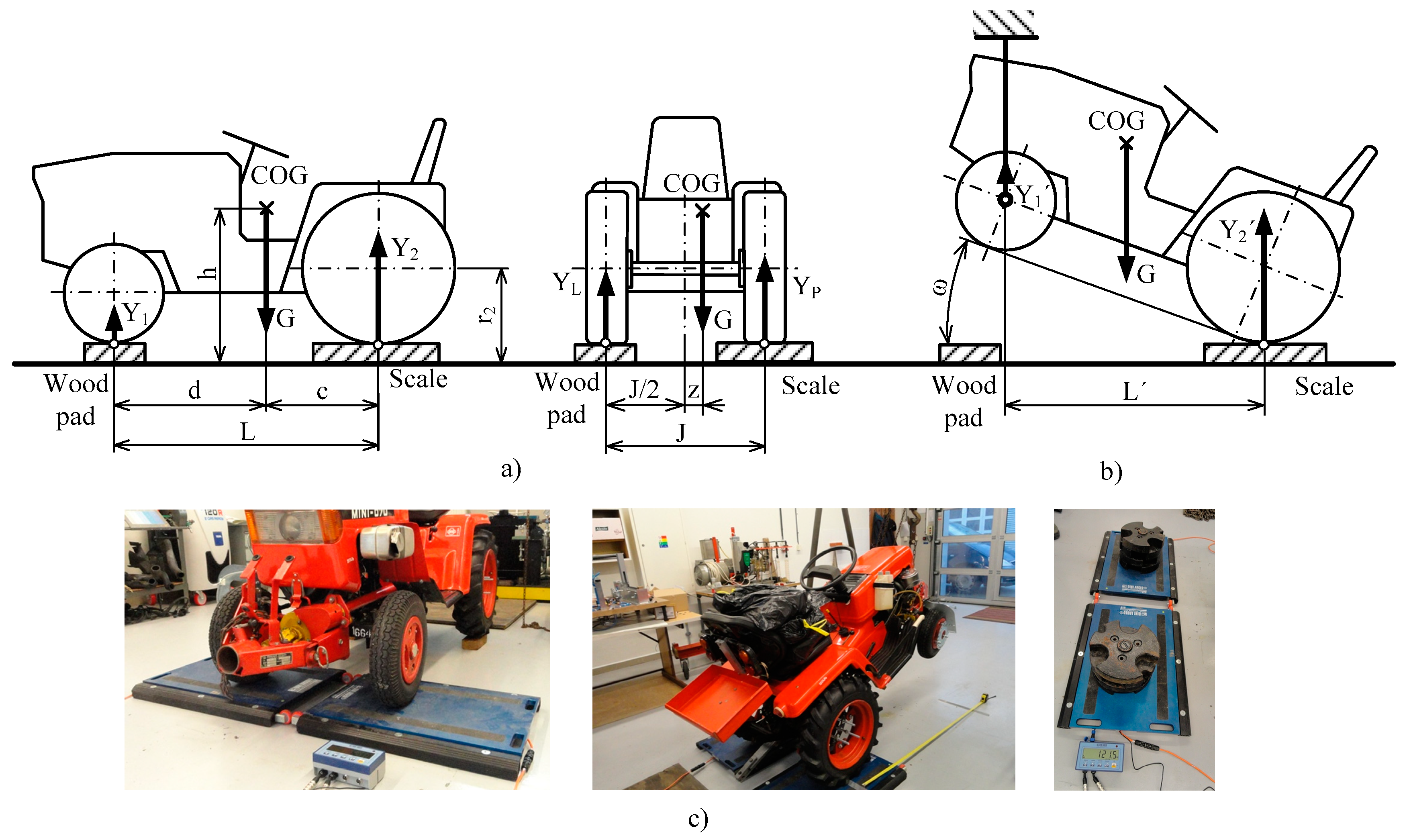
The static overturning angle was measured under experimental conditions. Using the tilting platform and the portal crane, the experimental tractor with right wheels touching the ground was tilted. When the tractor was inclined at the moment when it is resting in a state of unstable equilibrium, the experimental static overturning angle (Table 3) was measured by the digital protractor. Experiments were carried out with various rear wheel ballast weights at two overall widths on tyres. An increase in load causes an increase in tyre deformation characterized by the vertical distance of tyre section height i and distance v, as listed in Table 3.
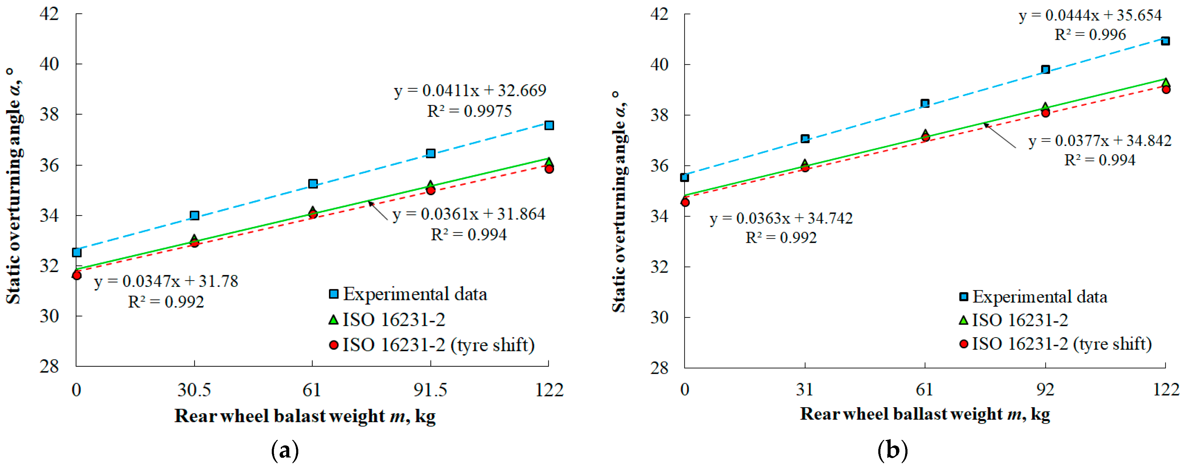
The effect of rear wheel ballast weight on the stability parameters, namely the vertical and longitudinal coordinates of COG and static overturning angle, was statistically analysed at standard and extended overall width on tyres. [23] confirmed the fact that the choice of selection of the rear track width in the stability of vehicles working on side sloping terrains is indeed a very important one. The rear wheel ballast weight was selected as an independent variable for regression analysis. Considering the 95% confidence interval, a statistically significant relationship between the variables was stated because the p-values of fitting a linear regression model (Figure 8) were lower than 0.05. The regression coefficients R2 of linear regressions were higher than 0.99. The statistical significance demonstrated the effect of the rear wheel ballast weight on the static overturning angle. This relationship allows predicting the tractor lateral stability at various rear wheel ballast weights. [24] statistically analysed the effect of the weight of tractor protective structures on the vertical coordinate of the COG regarding the tractor lateral stability. Regression analysis showed a significant relationship between the protective structure weight and tractor stability. [25] presented similar results in the paper aimed at the influence of the tractor weight on lateral stability. [26] also verified that the ballast weight can substantially change the lateral and longitudinal stability angles.

3.2. Comparison of ISO 16231-2 (2015) with Experimental Data and Tyre Deformation Analysis

Differences between the static overturning angles calculated according to standard [12] (Table 2) and experimental data (Table 3) at various rear wheel ballast weights are presented in Figure 8. The difference reached the highest value in case of the highest rear wheel ballast weight. The lowest difference was observed in case of the tractor without any ballast weight. Considering different slopes of linear regression models, the influence of rear wheel ballast weight on the difference between the data calculated according to [12] and experimental data are expressed by different constants of regression equations.
Practical experiments showed that the increase in rear wheel ballast weight affects the tyre deformation. When the tractor was tilted at the static overturning angle, the weight on the wheel touching the ground reached the maximal value. Therefore, the tyre deformation was measured in the state of unstable equilibrium. Using vertical distance of tyre section height i (Table 3), the parameters Δ1 and Δ2 were stated to calculate the vertical coordinate of COG and the static overturning angle considering the vertical tyre deformation (Table 4). The vertical tyre deformation decreases the vertical coordinate of COG and increases the static overturning angle α, as shown in Figure 9. The experiments showed that this parameter improves the tractor lateral stability.
When the tractor was tilted at the experimental static overturning angle, the parameter v (Table 3) needed for calculation of the tyre shift due to the lateral tyre deformation, was measured. The tyre shift m was calculated according to Equation (4), and the base line of the stability triangle AA′ was calculated according to Equation (5), as listed in Table 5. Considering the tyre shift, the base line of the stability triangle and the static overturning angle were decreased. The tyre shifts due to lateral tyre deformation negatively affected the tractor lateral stability, Figure 10.
Considering both effects of tyre deformation, namely the vertical tyre deformation and the tyre shift, the calculation methodology according to standard [12] was modified. The static overturning angles calculated in this way are presented in Figure 11 and Table 6 in case of the tractor with the standard and the extended overall width on tyres. The experiments presented a minimal decrease in the static overturning angle due to the tyre shift in comparison with an increase in it due to the vertical tyre deformation. The summary effect of the tyre deformation increased the static overturning angle.
Comparison of the experimental data with the data calculated according to [12] considering the vertical tyre deformation and tyre shift showed lower difference than in case of [12] ignoring the tyre deformation (Table 7). Besides the measuring errors, the difference between data calculated according to [12] and experimental data depends on the tyre deformation, regarding the results of experiments.
Considering the decrease in vertical coordinate of COG due to the vertical tyre deformation and the overall width on tyres due to tyre shift, the calculation method according to [12] was improved because the difference between calculated and experimental data was decreased. The constants of the regression equations (Figure 11) showed the different slope of the linear models of the calculated and experimental data. The difference between calculated and experimental data increases when the rear wheel ballast weight increases. The tyre deformation is a complex problem defined by various parameters ([27,28]). To detailly describe the tyre deformation and eliminate the increase in difference between the calculated and the experimental data due to the increase in the rear wheel ballast weight, complex measurements are needed. Regarding small absolute values of the percentage difference, there is no point in next complex measurements.
The results showed the difference between the experimental data and calculated according to [12] due to tyre deformation. In practice, this difference is not dangerous because the tyre deformation decreases the vertical coordinate of COG, increases the static overturning angle and therefore improves the tractor’s lateral stability. [19] studied the changes in lateral overturning angle by movement of the centre of gravity coordinates due to asymmetric connection of the harvest system to the tractor. The study of these authors presented a positive and negative change in static overturning angle at a decrease and increase in the vertical coordinate of COG.
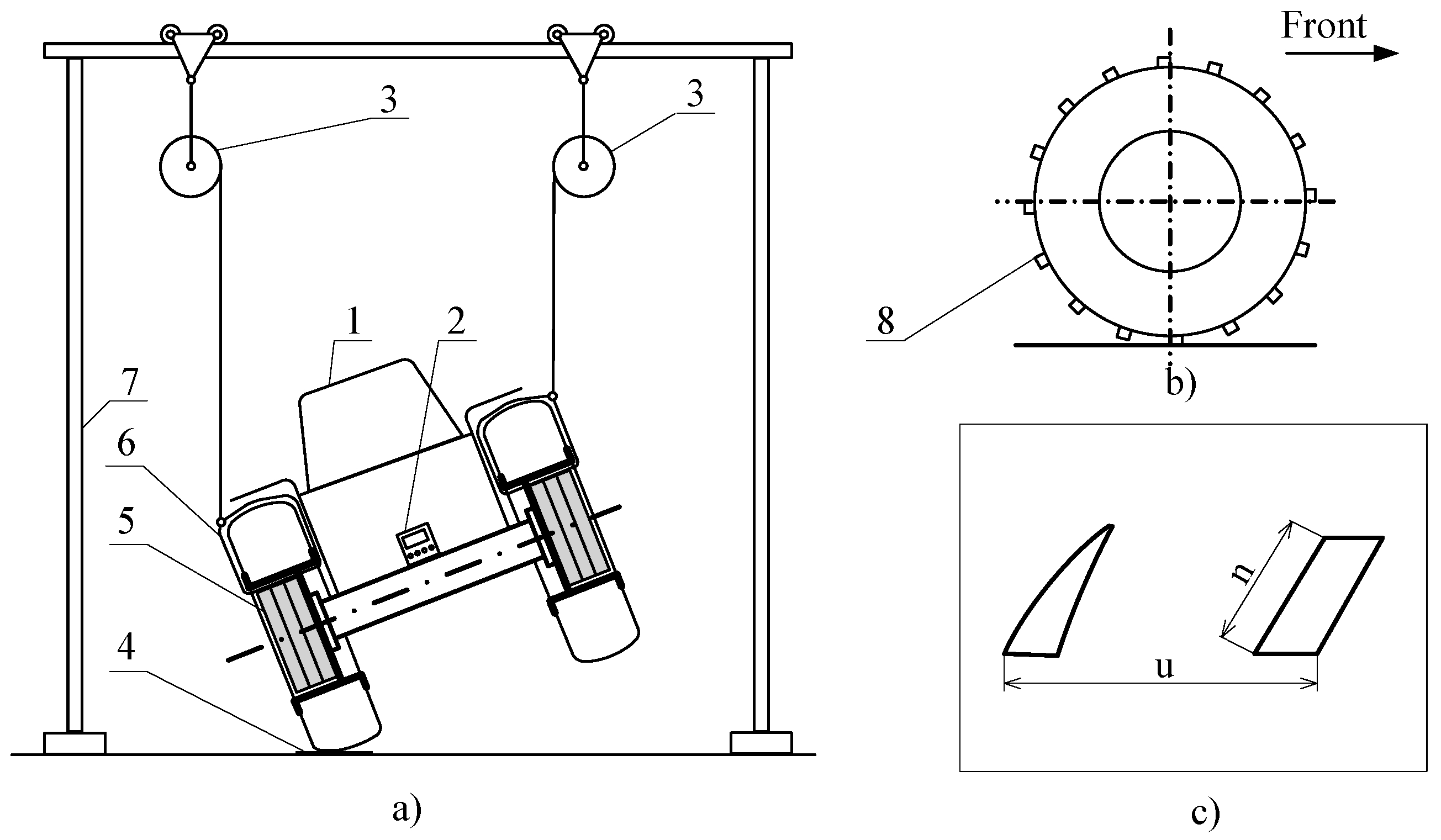
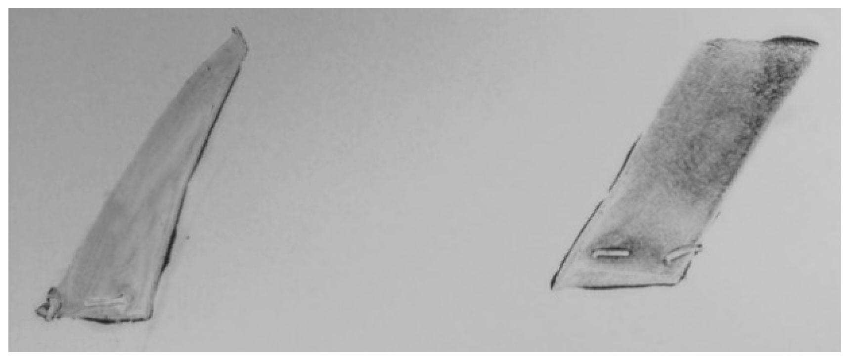
The tyre contact patch was analysed according to the length of rubber lug n and length of contact patch u, Figure 7c. The tyre footprints on the paper sheet showed the tyre contact patches of the tractor with various rear wheel ballast weights when the tractor was inclined at the static overturning angle. An example of the tyre contact patch of the tractor equipped with 122 kg of the rear wheel ballast weight (standard overall width on tyres o = 0.795 m) is shown in Figure 12.
Experimental measurements confirmed the fact that the rear wheel ballast weight affects the tyre deformation. Inclining the tractor at the experimental static overturning angle, the length of the tyre contact patch u (Table 8) depended on the rear wheel ballast weight due to the tyre deformation. The increase in the rear wheel ballast weight caused an increase in the length of contact patch (Figure 13a). Nonlinear regression equations pointed out that the tyre deformation is a complex problem. The coefficients of determination R2 higher than 0.98 and p-values lower than the significance level of 0.05 present a significant effect of tyre deformation due to the rear wheel ballast weight on the length of the contact patch.
On the other hand, the results of experiments showed that the length of rubber lug n (Table 8) did not change at various rear wheel ballast weights, Figure 13b). The coefficients of determination R2 lower than 0.1 and p-value higher than 0.05 express a statistically insignificant relationship between the rear wheel ballast weight and the length of the rubber lug. The increase in the rear wheel ballast weight causes an increase in the static overturning angle which compensates the increase in the length of the tyre rubber lug due to tyre deformation. Considering the experimental results, the dimensions of the tyre contact patch did not affect the calculation of the static overturning angle because the length of the contact patch u did not affect the distance AA′ and the length of rubber lug n did not change.
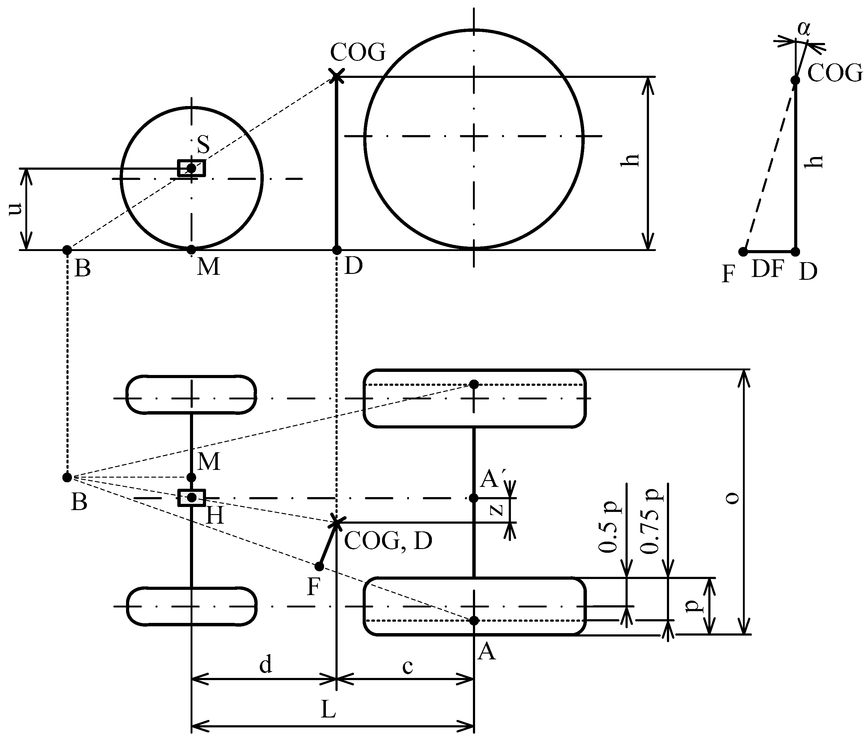
The tractor overturns around the rolling point when it reaches the limit value of the static overturning angle and loses stability (equilibrium). [6] present that the standard is intended for the calculation of static overturning angle in case of different tractor types with different agricultural tyres. Agricultural tyres are different in dimensions and elastic properties affecting the forces between the ground and tyre. The standard [12] defines the position of the force below the tyre in the rolling point of the fixed axle as three quarters (0.75) of the tyre width (Figure 4). If higher or lower value than 0.75 of tyre width p is considered, the calculated value of static overturning angle is higher or lower because the length of the base line of the stability triangle AA′ is changed. In the case of experimental tractor equipped with standard tyres, the higher inclination of the tractor (better lateral stability) due to higher wheel weight compensates the higher tyre deformation.

4. Conclusions

Four levels of the rear wheel ballast weight and extended overall width on tyres were applied to analyse the agricultural tractor lateral stability. The ballast weight placed in the rear wheels decreased the vertical coordinate of COG. The extended overall width on tyres widened the base line of the stability triangle of the tractor. The experiments confirmed the improvement of the tractor stability using the rear wheel ballast weight or increase in the overall width on tyres. The statistically significant relationship between the ballast weight and the height of COG can be used to predict the tractor lateral stability. The tests performed to characterize the tractor stability check the static overturning angle and are helpful for real operation conditions.
Comparing the static overturning angle calculated according to [12] with the experimental data, the difference was observed. The deference reached the values of 2.27%, 2.8%, 3.04%, 3.42% and 3.88% in the case of standard overall width on tyres and 2.14%, 2.61%, 3.11%, 3.67 and 3.99% in the case of extended overall width on tyres, at 0, 30.5, 61, 91.5 and 122 kg of the rear wheel ballast weight. Considering the measurement instruments with adequate precisions and statistical tools to decrease the standard measurement errors, the influence of the tyre deformation on the difference between [12] and experimental data were analysed. When the tractor was tilted, the vertical tyre deformation increased the static overturning angle due to the vertical shift of COG. This parameter is a component of the tyre deformation causing the improvement of the tractor stability. On the other hand, the lateral shift of the tyre decreased the static overturning angle due to the decrease in overall width on tyres. The tyre lateral shift is a component of the tyre deformation worsening the tractor stability and safety of the tractor operation. Both parameters act together resulting from the tyre deformation. Combination of the vertical tyre deformation and the lateral shift of the tyre decreased the difference between the experimental data and data calculated according to [12]. The difference reached the value of 1.81%, 1.33%, 0.98%, 0.73% and 0.22% in the case of standard overall width on tyres and 1.95%, 1.73%, 1.28%, 0.74 and 0.34% in the case of extended overall width on tyres at 0, 30.5, 61, 91.5 and 122 kg of the rear wheel ballast weight. The tyre contact patch was also analysed. The increase in the rear wheel ballast weight caused an increase only in the length of the contact patch, but this parameter does not affect the tractor lateral stability. The length of the rubber lug of the tyre tread pattern did not change because the tractor inclination corrected the influence of the weight increase on the tyre deformation. The result showed that the changes of the tyre contact patch due to tyre deformation did not affect the rolling point below the tyre and the static overturning angle.
Experiments showed the increase in the difference between experimental data and data calculated according to the standard [12], considering different constants of the regression equations of models. This problem results in the deformation characteristics of the tyre which can be described in detail by the complex analysis of the tyre deformation. Considering the minimal influence of this problem on the tractor lateral stability, the experiments defining the complex tyre deformation was not the aim of this article.
The static overturning angle calculated according to [12] is lower in comparison with the experimental data at both overall width on tyres and all rear wheel ballast weights. Based on results relating the tyre deformation analysis, it can be concluded that the difference is caused by the different tyre deformation when the front axle is lifted during the measurement of the COG coordinates in comparison with the tractor tilted at the static overturning angle during the experimental measurements. In practice, it means that the operation of the tractor according to [12] improves the tractor safety.

Author Contributions

Conceptualization, R.A. and R.D.; Data curation, E.M.; Formal analysis, Z.T. and K.K.; Funding acquisition, Z.T.; Investigation, R.M., R.A. and J.M.; Methodology, R.M., R.A. and J.M.; Project administration, K.K.; Software, R.D. and E.M.; Supervision, Z.T.; Visualization, R.D. and E.M.; Writing—original draft, R.M.; Writing—review & editing, K.K. All authors have read and agreed to the published version of the manuscript.

Funding

This research r received funding from project VEGA 1/0724/19 mentioned in Acknowledgements.

Institutional Review Board Statement

Not applicable.

Informed Consent Statement

Not applicable.

Data Availability Statement

Not applicable.

Acknowledgments

VEGA 1/0724/19 “Research, Design and Application of Special Driving Wheels for Drawbar Properties Improvement and Elimination of Soil Damage under Operation of Cars and Tractors”.

Conflicts of Interest

The authors declare no conflict of interest

References

  1. Bietresato, M.; Mazzetto, F. Definition of the layout for a new facility to test the static and dynamic stability of agricultural vehicles operating on sloping grounds. Appl. Sci. 2019, 9, 4135. [Google Scholar] [CrossRef] [Green Version]
  2. Demšar, I.; Bernik, R.; Duhiovnik, J. A mathematical model and numerical simulation of the static stability of a tractor. Agric. Conspec. Sci. 2012, 77, 143–150. [Google Scholar]
  3. Hunter, A.G.M. A review of research into machine stability on slopes. Saf. Sci. 1993, 16, 325–339. [Google Scholar] [CrossRef]
  4. Kosiba, J.; Varga, F.; Mojžiš, M.; Bureš, Ľ. The load characteristics of tractor Fendt 926 Vario for simulation on test device. Acta Fac. Tech. 2012, 17, 63–72. [Google Scholar]
  5. Hujo, Ľ.; Tkáč, Z.; Jablonický, J.; Uhrinová, D.; Halenár, M. The action of force measurement for the three-point hitch of a tractor. Agron. Res. 2017, 15, 162–169. [Google Scholar]
  6. Bietresato, M.; Mazzetto, F. Proposal of an advanced facility to perform static and dynamic tests of stability on agricultural machines. Chem. Eng. Trans. 2017, 58, 151–156. [Google Scholar]
  7. Khorsandi, F.; Ayers, P.D.; Freeland, R.S.; Wang, X. Modeling the effect of liquid movement on the center of gravity calculation of agricultural vehicles. J. Terramechanics 2018, 75, 37–48. [Google Scholar] [CrossRef]
  8. Zhang, Q.; Su, C.; Zhou, Y.; Zhang, C.; Ding, J.; Wang, Y. Numerical Investigation on Handling Stability of a Heavy Tractor Semi-Trailer under Crosswind. Appl. Sci. 2020, 10, 3672. [Google Scholar] [CrossRef]
  9. Emam, M.A.; Marzouk, M.; Shaaban, S. A monitoring device for forklift’s stability triangle. Int. J. Veh. Mech. Engines Transp. Syst. 2017, 43, 16–27. [Google Scholar] [CrossRef] [Green Version]
  10. Demšar, I.; Duhiovnik, J. Simulating tractor’s static stability in relation to its position and slope. In Proceedings of the Eurosim 2007, Ljubljana, Slovenia, 9–13 September 2007; pp. 1–11. [Google Scholar]
  11. Gibson, H.G.; Elliot, K.C.; Person, S.P.E. Side slope stability of articulated-frame logging tractors. J. Terramechanics 1971, 8, 65–79. [Google Scholar] [CrossRef]
  12. ISO 16231-2. Self-Propelled Agricultural Machinery—Assessment of Stability—Part 2: Determination of Static Stability and Test Procedures; International Organization for Standardization: Geneva, Switzerland, 2015. [Google Scholar]
  13. Abrahám, R.; Majdan, R.; Drlička, R. Special tractor driving wheels with two modification of spikes inclination angle. Agron. Res. 2019, 17, 333–342. [Google Scholar]
  14. Majdan, R.; Abrahám, R.; Tkáč, Z.; Mojžiš, M. Drawbar parameters of tractor with prototypes of driving wheels and standard tyres. Acta Technol. Agric. 2018, 21, 63–68. [Google Scholar] [CrossRef] [Green Version]
  15. Abrahám, R.; Majdan, R.; Mojžiš, M. Design and verification of tractor wheels equipped with automatically extensible blades. Acta Technol. Agric. 2013, 16, 49–52. [Google Scholar] [CrossRef]
  16. Jandačka, D. Biomechanical Basis of Physical Exercises; Masaryk University in Brno: Brno, Czech Republic, 2017; p. 152. (In English) [Google Scholar]
  17. ISO 789-6. Agricultural Tractors—Test Procedures—Part 6: Centre of Gravity; International Organization for Standardization: Geneva, Switzerland, 1993. [Google Scholar]
  18. Majdan, R.; Tkáč, Z.; Abrahám, R.; Kosiba, J. Teória a Konštrukcia Traktorov (Theory and Design of Tractors); Slovak University of Agriculture in Nitra: Nitra, Slovak Republic, 2012; p. 100. (In Slovak) [Google Scholar]
  19. Choi, K.; Kim, S.; Hong, S. Analysis of static stability by modified mathematical model for asymmetric tractor-harvester system: Changes in lateral overturning angle by movement of center of gravity coordinates. J. Biosyst. Eng. 2017, 42, 127–135. [Google Scholar]
  20. Molari, G.; Rondelli, V. On the definition of narrow-track wheeled agricultural tractors. Biosyst. Eng. 2004, 88, 75–80. [Google Scholar] [CrossRef]
  21. Franceschetti, B.; Lenain, R.; Rondelli, V. Comparison between a rollover tractor dynamic model and actual lateral tests. Biosyst. Eng. 2014, 127, 79–91. [Google Scholar] [CrossRef]
  22. Bietresato, M.; Mazzetto, F. Stability tests of agricultural and operating machines by means of an installation composed by a rotating platform (the “turntable”) with four weighting quadrants. Appl. Sci. 2020, 10, 3786. [Google Scholar] [CrossRef]
  23. Gravalos, I.; Gialamas, T.; Loutridis, S.; Moshou, D.; Kateris, D.; Xyradakis, P.; Tsiropoulos, Z. An experimental study on the impact of the rear track width on the stability of agricultural tractors using a test bench. J. Terramechanics 2011, 48, 319–323. [Google Scholar] [CrossRef]
  24. Franceschetti, B.; Rondelli, V.; Ciuffoli, A. Comparing the influence of roll-over protective structure type on tractor lateral stability. Saf. Sci. 2019, 115, 42–50. [Google Scholar] [CrossRef]
  25. Ahmadi, I. Development of a tractor dynamic stability index calculator utilizing some tractor specifications. Turk. J. Agric. For. 2013, 37, 203–211. [Google Scholar]
  26. Ayers, P.; Conger, J.B.; Comer, R.; Troutt, P. Stability analysis of agricultural off-road vehicles. J. Agric. Saf. Health 2018, 24, 167–182. [Google Scholar] [CrossRef] [PubMed]
  27. Gorshkov, Y.G.; Starunova, I.N.; Kalugin, A.A.; Troyanovskaya, I.P. Investigation of the slope angle influence on the loading imbalance of the wheeled vehicle sides and the change in the center of gravity vector direction. J. Phys Conf. Ser. 2019, 1177, 12005. [Google Scholar] [CrossRef]
  28. Levenkov, Y.Y.; Vol’skaya1, N.S.; Rusanov, O.A. Simulation of the tire enveloping properties in case of the unmanned car wheel interaction with a rigid uneven surface. Mater. Sci. Eng. 2019, 534, 12–23. [Google Scholar] [CrossRef]
Figure 1. Tractor driver seat: (a) three sandbags to simulate the human body, (b) empty seat.
Applsci 11 00381 g001
Figure 2. Determination of COG coordinates: (a) scheme for calculation of longitudinal coordinate of COG: (b) scheme for calculation of vertical coordinates of COG [18], (c) weighting scales measuring the reactions of tractor wheels and steel discs (ballast weight): L—wheelbase; c, d—longitudinal coordinates of COG; h—vertical coordinate of COG; J—tread width; G—tractor weight; Y1, Y2, YP, YL,—ground reactions; r2—static rear wheel radius; ω—lifting angle, L′—vertical projection of wheelbase, Y1, Y2—reaction when the tractor is in raised position.
Applsci 11 00381 g002
Figure 3. Test of tractor lateral stability: 1—tyre, 2—wheel rim, 3—ballast weight, 4—tilting platform, 5—portal, 6—chain hoist, 7—digital protractor.
Applsci 11 00381 g003
Figure 4. Determination of tractor lateral stability according to standard [12]: o—overall width on tyres of the fixed axle, p—width of tyres on fixed axle, u—height of pivot point of the swelling axle, L—wheelbase, c, d—longitudinal coordinates of COG; h—vertical coordinate of COG; z—lateral position of COG; α—static overturning angle, AA′—base line of stability triangle, DF—slope line.
Applsci 11 00381 g004
Figure 5. Determination of vertical shift of centre of gravity due to vertical tyre deformation.
Applsci 11 00381 g005
Figure 6. Determination of tyre shift due to lateral tyre deformation: (a) no rear wheel ballast weight, (b) highest rear wheel ballast weight, (c) vertical line of the steel set square touching corner of the tyre-tread pattern and wheel rim.
Applsci 11 00381 g006
Figure 7. Analysis of tyre contact patch: (a) tractor at static overturning angle, (b) tyre position during experiments, (c) sketch of tyre contact patch on the paper sheet, 1—tractor, 2—digital protractor, 3—chain hoist, 4—sheet of paper, 5—ballast weight, 6—strap belt, and 7—portal.
Applsci 11 00381 g007
Figure 8. Static overturning angle and coordinates of COG: (a) standard overall width on tyres (o = 0.795 m), (b) extended overall width on tyres (o = 0.885 m).
Applsci 11 00381 g008
Figure 9. Influence of the vertical tyre deformation on the static overturning angle calculated according to standard [12]: (a) standard overall width on tyres (o = 0.795 m), (b) extended overall width on tyres (o = 0.885 m).
Applsci 11 00381 g009
Figure 10. Influence of the tyre shift (lateral tyre deformation) on the static overturning angle calculated according to standard [12]: (a) standard overall width on tyres (o = 0.795 m), (b) extended overall width on tyres (o = 0.885 m).
Applsci 11 00381 g010
Figure 11. Comparison of static overturning angle calculated according to standard [12], [12] considering the vertical tyre deformation and tyre shift with experimental data: (a) standard overall width on tyres (o = 0.795 m), (b) extended overall width on tyres (o = 0.885 m).
Applsci 11 00381 g011
Figure 12. Experimental example for tyre contact patch.
Applsci 11 00381 g012
Figure 13. Dimensions of tyre contact patch: (a) length of contact patch, (b) length of rubber lug.
Applsci 11 00381 g013
Table 1. Specifications of the experimental tractor Mini 070.
Parameter-Value
Cylinder number of engine-1
Displacement of engine, ccm-400
Engine power, kW/rpm-8/3600
Wheelbase L, m-1.15
Overall width on tyres of the fixed axle o, mStandard0.795
Extended0.885
Table 2. Data calculated according to standard [12].
Rear Wheel Ballast Weight, kg 030.56191.5122
Vertical and longitudinal coordinates of COGh, m0.4460.4360.4270.4200.413
d, m0.7080.7350.7600.7810.801
c, m0.4420.4150.3900.3690.349
Static overturning angleα, °Standard overall width on tyres (0.795 m), AA′ is 0.361 m
31.7133.0634.2035.2236.13
Extended overall width on tyres (0.885 m), AA′ is 0.406 m
34.6836.0937.2838.3839.30
Table 3. Experimental data.
Rear Wheel Ballast Weight, kg 030.56191.5122
Standard overall width on tyres (0.795 m)α, °Average32.5534.0135.2736.4737.59
Standard deviation0.3870.4050.2910.3240.378
i, mAverage0.05410.04900.04580.04190.0348
Standard deviation0.00170.00210.00150.00080.0012
v, mAverage35.6834.6434.5032.6229.87
Standard deviation0.00120.00140.00080.00110.0013
Extended overall width on tyres (0.885 m)α, °Average35.5337.0638.4839.8140.93
Standard deviation0.3850.2170.1290.3610.281
i, mAverage0.05350.04790.04250.03650.0319
Standard deviation0.00130.00090.00160.00090.0011
v, mAverage40.3038.1637.2833.4231.16
Standard deviation0.00120.00130.00090.00140.0016
Table 4. Data calculated according to standard [12] considering the vertical tyre deformation.
Rear Wheel Ballast Weight, kg 030.56191.5122
Standard overall width on tyres (0.795 m)Δ1, m0.01890.02060.02160.02320.0265
Δ2, m0.00830.00850.00850.00860.0093
hdef, m0.4370.4270.4180.4100.403
α, °32.2133.6134.7735.0136.65
Extended overall width on tyres (0.885 m)Δ1, m0.01710.01910.02140.02420.0272
Δ2, m0.00750.00790.00830.00890.0095
hdef, m0.4380.4280.4190.4110.404
α, °35.337.0638.4839.8140.93
Table 5. Calculated data considering the tyre shift (lateral tyre deformation).
Rear Wheel Ballast Weight, kg 030.56191.5122
Standard overall width on tyres (0.795 m)m, m0.001060.001580.002110.002530.00314
AA′, m0.3610.3600.3590.3590.358
α, °31.6232.9234.0735.0135.87
Extended overall width on tyres (0.885 m)m, m0.001530.001990.002480.003020.00361
AA′, m0.4050.4040.4040.4030.402
α, °34.5735.9437.1438.1139.02
Table 6. Calculated data considering vertical tyre deformation and tyre shift.
Rear Wheel Ballast Weight, kg 030.56191.5122
Standard overall width on tyres (0.795 m)α, °32.2433.6334.8135.7936.68
Extended overall width on tyres (0.885 m)35.2136.6237.8338.9139.88
Table 7. Percentage difference between calculated and experimental data.
Rear Wheel Ballast Weight, kgStandard Overall Width on Tyres (0.795 m)Extended Overall Width on Tyres (0.885 m)
ISO 16231-2 ISO 16231-2 Considering the Vertical Tyre Deformation and Tyre ShiftISO 16231-2 ISO 16231-2 Considering the Vertical Tyre Deformation and Tyre Shift
02.570.952.400.91
30.52.801.112.611.18
613.041.293.111.69
91.53.421.853.672.27
1223.882.423.992.57
Table 8. Dimensions of tyre contact patch at various rear wheel ballast weights.
Rear Wheel Ballast Weight, kgStandard Overall Width on Tyres (0.795 m)Extended Overall Width on Tyres (0.885 m)
030.56191.5122030.56191.5122
Length of rubber lug n, m0.05880.05850.05860.05830.05870.05460.05470.05460.05490.0547
Standard deviation, m0.00110.00120.00090.00090.00140.00060.00080.00070.00120.0011
Length of contact patch u, m0.1200.1240.1260.1290.1310.1280.1290.1300.1320.133
Standard deviation, m0.0010.00080.00150.00110.00070.00870.00120.00140.00110.0007
Publisher’s Note: MDPI stays neutral with regard to jurisdictional claims in published maps and institutional affiliations.

