Abstract
Clinical studies have demonstrated that robot-involved therapy can effectively improve the rehabilitation training effect of motor ability and daily behavior ability of subjects with an upper limb motor dysfunction. This paper presents an impedance-based assist-as-needed controller that can be used in robot-aided rehabilitation training for subjects with an upper extremity dysfunction. Then, the controller is implemented on an end-effector upper extremity rehabilitation robot which could assist subjects in performing training with a spatial trajectory. The proposed controller enables subjects’ arms to have motion freedom by building a fault-tolerant region around the rehabilitation trajectory. Subjects could move their upper limb without any assistance within the fault-tolerant region while the robot would provide assistance according to the subjects’ functional ability when deviating from the fault-tolerant region. Besides, we also put forward the stiffness field around the fault-tolerant region to increase the robot’s assistance when subjects’ hand is moving outside the fault-tolerant region. A series of columnar rigid walls would be constructed in the controller according to the subjects’ functional ability, and the stiffness of the wall increases as the motion performance deteriorates. Furthermore, the controller contains five adjustable parameters. The controller would show different performances by adjusting these parameters and satisfy the requirement of robot-aided rehabilitation training at different rehabilitation stages such as passive, assistant, active, and resistant training. Finally, the controller was tested with an elderly female participant with different controller parameters, and experimental results verified the correctness of the controller and its potential ability to satisfy the training requirements at different rehabilitation stages. In the close future, the proposed controller in this work is planned to be applied on more subjects and also patients who have upper limb motor dysfunctions to demonstrate performance of the controller with different parameters.
1. Introduction
In recent years, the number of subjects with upper extremity motor dysfunctions caused by stroke, spinal cord injuries, and accidents has been dramatically increasing year by year [1], severely limiting their motor and activities of daily living (ADL) abilities. This not only brings physical inconvenience to the subjects but also brings financial and mental burden to their families. Research results have showed that compared with the traditional manual rehabilitation therapy, robot-aided rehabilitation training could carry out high-intensity repetitive and task-oriented training tasks [2], and clinical research studies have also shown that robot-aided rehabilitation therapy could effectively improve the rehabilitation effect on patients’ upper extremity motor abilities [3,4]. To satisfy the patient’s requirements at different rehabilitation stages, different types of upper limb rehabilitation robots have been developed, which can be divided into two categories [5]: the end-effector type [6,7] and the exoskeleton type [8,9]. Generally, exoskeleton type upper limb rehabilitation robots could implement rehabilitation training of a single joint; however, additional interactive forces and torques between the patient’s arm and the robot would occur [10]. Compared with the traditional rehabilitation training methods, the end-effector type upper limb rehabilitation robot has better superiority during upper limb rehabilitation training [11]. Clinical comparative trial results have also showed that compared with the exoskeleton upper limb rehabilitation robot, intervention with the end-effector rehabilitation robot was more effective in terms of the active participation of patients with mild and severe stroke [12].
According to the Brunstorm theory, patients with an upper limb motor disorder in the early recovery stage experience difficulties in moving their arm, and therapists or robots are required to carry out repeated passive training. Therefore, a stiff position controller is required to be applied in such passive training. The rehabilitation effect of the passive training method would be not great with the recovery of the patient’s motor ability because the active participation of the patients will be ignored in those position controllers. For patients with partial motor control ability, robot intervention to a minimum extent could stimulate and promote the brain neuroplasticity of patients [13,14]. Studies have shown that task-oriented rehabilitation training is only effective when it is associated with task-oriented movements involving effort by the subject actively [15]. Therefore, a controller needs to be developed to provide necessary assistance or correction to complete rehabilitation training tasks according to the patient’s functional ability. Controllers with such characteristics are called assist-as-needed (AAN) controllers, also known as assistance or corrective controllers. At present, AAN controllers have been used in lower limb rehabilitation [16], finger rehabilitation [17], and upper limb rehabilitation [18] to stimulate the patient’s active participation during rehabilitation training. The results of a clinical trial proved that an upper limb rehabilitation robot with an AAN controller could provide intensive and repeated rehabilitation training and could also promote the active participation and motion performance of patients, promoting the motor recovery [19].
Regarding robot-aided training with the AAN characteristic, impedance control is often applied to assist patients during robot-aided rehabilitation training tasks [20]—the schematic diagram is shown in Figure 1. Clinical studies on stroke patients [21,22] showed that rehabilitation robots with the impedance control strategy have a better effect on reducing the upper limb muscle strength and improving the motor function of patients than robot-assisted therapy that simply mimics traditional therapy [23,24,25]. Although the impedance control strategy allows a patient’s arm to deviate from the training trajectory, the patient’s spatial freedom is limited. Assistance from the robot is always given as a restoring force to assist the patients once they are deviating from the planned trajectory. Therefore, scholars have developed an impedance-based AAN strategy to increase the patient’s freedom, which can be mainly divided into two categories: the band-type controller and the window-type controller. The window-type controller defines a predetermined trajectory and a moving window that allows the patient’s arm to move freely. When the patient’s arm lies outside the moving window, the patient’s arm would be corrected into the moving window by the robot’s assistance force [26,27]. Another band-type controller is based on the fault-tolerant region (FTR), which constructs a fault-tolerant band that allows the patient to move freely by establishing the inner and outer boundary of the FTR. The patient’s spatial freedom is limited in the window-type AAN controller, while the band-type AAN controller allows the patient to have complete freedom and choose his/her own trajectory without being assisted by the robot. The patient’s arm has complete freedom when moving in the FTR, while the robot will apply an assistance force to assist the patient’s arm to finish the rehabilitation training task when deviating from FTR. Research studies have also been conducted to explore increasing the patient’s freedom. Ying et al. [28] first developed a rope-driven exoskeleton rehabilitation robot and then added a fault-tolerant area around the predetermined trajectory to increase the patient’s spatial freedom. Hamed et al. [29] validated the feasibility by adding a plane channel around the predetermined trajectory based on a two-link rehabilitation robot. Although the band-type AAN controller has shown positive results in clinical trials, its tendency or ‘‘slacking’’ for the patient to rely heavily on the assistance force has been recorded [30]. The robot will not apply any assistance or correction as long as the patient’s arm is moving within the FTR, which will greatly reduce the active participation of patients. A velocity curve could be added in the FTR which will build a virtual movement in the FTR. When the patient’s arm is stagnant or moving too slowly in the FTR, the controller will generate a moving wall to push the patient’s arm to catch up with the virtual movement to complete the training task and avoid the slacking.
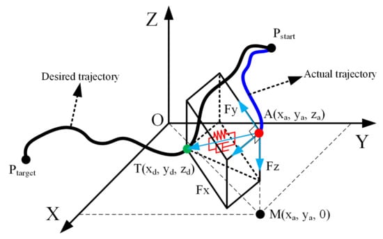
Figure 1.
The diagram scheme of the impedance control; the black curve is the desired trajectory, while the blue curve is the actual trajectory.
To better adjust the assistance force of the AAN controller, it is necessary to evaluate the patient’s real-time motor ability or functional ability. One can conclude that there are mainly two classifications for the evaluation of a patient’s functional ability based on the current literatures: the sensor-based [31,32] and model-based [33] evaluation techniques. Although there is more of a theoretical basis for the evaluation of upper limb motor ability for model-based methods, the modeling results are difficult to use to accurately evaluate the patient’s true motion intention, while sensor-based evaluation methods can more intuitively express the patient’s motion state. Some studies have already used the position deviation between the actual trajectory of a patient’s hands and the expected trajectory which was calculated to represent the functional ability of patients during rehabilitation training [34].
Besides, the AAN control strategies are mainly applied to the exoskeleton upper limb rehabilitation robots currently, while there is relatively little research based on the end-effector rehabilitation robot. So far, only a small number of planar end-effector rehabilitation robots such as MIT-Manus [6] and the Bracciio Di Ferro rehabilitation robot [35] have realized the AAN rehabilitation strategy on the specific plane trajectory. In this paper, an impedance-based AAN controller is proposed and implemented in an end-effector upper limb rehabilitation robot, which can carry out three-dimension trajectory rehabilitation training. The controller can adjust the assistance force according to the patient’s functional ability to realize the assistance training of the patient’s arm. In addition, the controller can also satisfy the training requirements of different rehabilitation stages by regulating these adjustable parameters of the controller. For example, active training and resistant training in the later stage of rehabilitation therapy, passive training in the early stage of rehabilitation, and assistance training in the middle stage of rehabilitation where patients have partial upper limb motor control ability. Compared with previous research, the main contributions in this study are summarized as follows:
- Compared with window-type controllers, the impedance-based AAN controller proposed in this work enables a patient’s arm to have complete motion freedom within the FTR by building a virtual tunnel around the rehabilitation trajectory and has been implemented on an end-effector rehabilitation robot that can perform rehabilitation training on a three-dimension (3D) trajectory. When the patient’s arm deviates from the FTR, the robot will apply a time-varying assistance force according to the patient’s functional ability during the rehabilitation training. Meanwhile, when the patient’s arm is stagnant or moving too slowly in the FTR, the controller will generate a moving wall to push patient’s arm to complete the training task to avoid slacking.
- The AAN controllers in existing studies, whether band-based or windows-based controllers, would construct a fixed stiffness wall to assist the patient’s arm when their functional ability is getting worse. In the impedance-based AAN controller proposed in this paper, a spatial stiffness field contains a series of columnar stiffness walls will be constructed during the rehabilitation training to assist the patient’s arm, and the stiffness of the wall will increase with the deterioration of the patient’s upper limb functional ability. This is not found in the current research.
- Few of the existing studies on AAN control strategies have the ability to cover the entire upper limb rehabilitation stages, such as passive, assistant, active, and resistant training. So far, although it is feasible to switch different controllers on one rehabilitation robot to satisfy the training requirements of different rehabilitation stages [36], it is relatively rare to use a single controller to provide training requirements for the entire rehabilitation stage. The impedance-based AAN controller proposed in this paper could provide training requirements for the entire rehabilitation stage by adjusting the controller parameters, which can greatly simplify the development difficulty of the software and rehabilitation training system.
The remaining sections in this work are organized as follows: we first describe the design, kinematics, and dynamics model of the end-effector rehabilitation robot in Section 2; Section 3 presents the development of the impedance-based AAN controller and the parameters adjustment for different rehabilitation training mode of the controller; the validation experiment and results of different AAN controller parameters showing the correctness of the controller in different rehabilitation modes are presented in Section 4; discussions and conclusions of our research are presented in Section 5.
2. Description of the Rehabilitation Robot
2.1. Design of the Rehabilitation Robot
Figure 2 shows the three-dimensional model of the rehabilitation robot prototype designed in the research project of the author, which can perform rehabilitation training in an arbitrary trajectory within the human’s physiological workspace of the upper limb. The overall structural dimensions of the rehabilitation robot are shown in Figure 2a. Compared with the unilateral upper limb rehabilitation robot, only the manipulator at the side of the affected arm of the patient is used for the rehabilitation training when using the rehabilitation robot developed in this paper, and the manipulator at the opposite side moves to a safe position, as shown in Figure 2b, c. Besides, the rehabilitation robot developed in this paper can also implement bilateral rehabilitation exercises; however, it is not involved in this study. As shown in Figure 2, the rehabilitation robot is mainly composed of the body module and the motion assistance module. The body module is mainly used to support the motion assistance module, control cabinet of manipulator, the electrical structure, and the control computer. There are two perpendicular planes at the top of the body module that used to connect the motion assistance module. The core part of the motion assistance module includes two commercial manipulators for assisting the patient’s arm to perform rehabilitation training. Each manipulator has seven degrees of freedom (DOFs), and each joint of the manipulator is equipped with a torque sensor and a position sensor. The torque sensors are mounted on a Harmonic Drive gear and therefore measure the joint torque acting on the links. A handlebar is installed at the end of the manipulator to connect with the patient’s hand through a bandage.
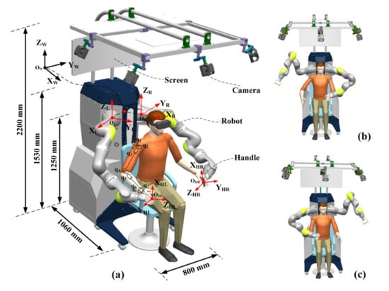
Figure 2.
The three-dimensional model of the rehabilitation robot. (a) is the overview of the rehabilitation robot; (b) is the unilateral rehabilitation training schematic of the left arm; (c) is the unilateral rehabilitation training schematic of the right arm.
The two manipulators of the rehabilitation robot are installed vertically on a vertical plane perpendicular to the outside of the body module. To obtain an optimal distribution of the cooperative workspace and dexterity workspace of the two manipulators, according to reference [37], the two manipulators are installed at a 90-degree angle, and the distance between the base of the manipulators is designed to be 520 mm, which enables the rehabilitation robot to be used by patients with different shoulder width. Considering the comfort and grip of patients when using the handle, the width of the handle was designed to be 120 mm so that it could satisfy the needs of most patients. Besides, a screen is installed on the column of the body module, which is used for debugging.
2.2. Kinematics Model
The kinematic model of the upper limb rehabilitation robot is mainly used to describe the mapping relationship of the handle to the world coordinate system during rehabilitation training. The intersection of the axes of joints, 1, is chosen as the origin of the global coordinate system, and the detailed relationship between the global coordinate system, robot coordinate system, and handle coordinate system is shown in Figure 3, where and are the handle frame and base frame of the left manipulator, respectively, and are the handle frame and base frame of the right manipulator, respectively, and is the global frame. The manipulator coordinate frames, the Denavit and Hartenberg (DH) parameters, and the kinematics equation of the manipulator are described in detail in the author’s previous works [38,39]. Take the right arm for example, the mapping relationship of the hand to the global coordinate system can be established:
where is the orientation matrix and is the position vector; and are the transformation matrix between the handle and the robot flange and the transformation matrix between the robot base and the global coordinate frame, respectively; is the transformation matrix between the flange and the base of the manipulator.
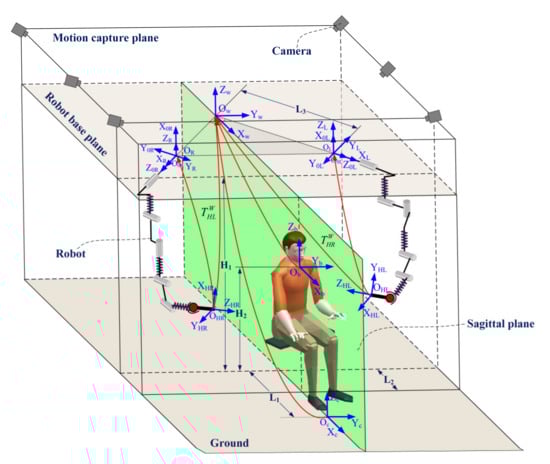
Figure 3.
The schematic diagram of the coordinate frames relationship.
2.3. Dynamics Model and Control
Regarding the end-effector rehabilitation robot developed in this paper, the dynamic analysis of the rehabilitation robot is mainly to carry out dynamic modeling and analysis for the two commercial manipulators. In general, the dynamic model of the serial manipulator can be derived through the Lagrangian equation or Newton–Euler equation. Once given the joint position, joint velocity, and joint acceleration, the dynamics model in the joint space can be written:
where are the applied torques by actuators; is the inertial matrix; denotes the centrifugal and Coriolis matrix; is the gravity vector; denotes the friction vector; is the external wrench applied on the end-effector, and is the Jacobian matrix.
According to Equation (2), Hogan [20] proposed the impedance control algorithm that describes a dynamic relationship between the motion and the force of the end of a manipulator, which can make the manipulator behave as a mass-spring-damping system when it is driven by an external wrench, or following a determined reference trajectory. For convenience of expression, the impedance control algorithm in the joint space of the manipulator makes the manipulator behave as a mass-spring-damping system, and the control law of impedance control in the joint space can be expressed as:
where , , and represent, respectively, the inertial, the damping, and the stiffness desired matrices at the joint level. In order to derive the impedance control model of the manipulator in Cartesian space, it is necessary to apply the geometric Jacobian matrix of the manipulator to map the robot joint space model to Cartesian space, as shown in Figure 4:
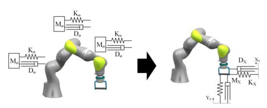
Figure 4.
Schematic diagram of the transformation from the joint space impedance control model to the Cartesian space impedance model.
Therefore, the control equation of the impedance control model of manipulator in Cartesian space is obtained [40]:
where , , ;, , and represent, respectively, the virtual inertial, damping, and stiffness matrices, defined at the Cartesian level. Therefore, the appropriate impedance parameters can be constructed to achieve the desired compliance level of the manipulator. When we expect the manipulator to work in position control mode, we could construct the stiffness parameters of the manipulator as ; now, the manipulator’s controller becomes a position controller combining the Equations (3), (4), and (9). When we expect the manipulator to work under torque control mode, we need to construct the stiffness parameters of the manipulator . When the manipulator is expected to work under impedance control, the stiffness parameters that meet the requirements need to be formulated according to the requirements.
3. Impedance-Based Assist-as-Needed Controller
3.1. Design of the Controller
In order to realize the assistance rehabilitation training of the upper limb, a band-type AAN controller is designed in this paper by building a virtual FTR around the predetermined trajectory. The patient’s arm has complete freedom when moving within the FTR, which is a zero-impedance region, while the robot would provide a time-varied adjustable assistance force when deviating from the FTR. The patient’s functional ability is evaluated through the deviation between the patient’s hand and the predetermined trajectory during the rehabilitation training. The greater the deviation, the worse the patient’s functional ability is, approximately, and the greater the assistance force needed to be applied by the robot is to assist the patient’s arm to finish the rehabilitation task. Generally, the movement of a patient’s upper extremity during the training is slow. Studies have shown that compared with fast rehabilitation training, slow rehabilitation training has a better effect on the recovery of a patient’s upper limb motor function [41]. Otherwise, compared with the influence of velocity on the robot’s assistance force, the impact of position is more significant. Therefore, the AAN controller proposed in this paper mainly focuses on the position of the patient’s upper extremity, and the model between the motion of the patient’s upper limb and the robot’s assistance force can be established as follows:
where is the stiffness coefficient matrix; and are the positions on the actual and desired trajectory of the patient’s arm, respectively.
A robot-aided rehabilitation control strategy based on the Equation (9) has been realized in research [42,43]; however, the spatial motion freedom of the patient’s upper limb in these studies is limited. In order to solve this tendency, a spatial channel with an adjustable radius was added to the rehabilitation trajectory in the impedance-based AAN controller, which enables the patient’s upper limb to have complete freedom, which is shown in Figure 5. The black curve in Figure 5 is the predetermined trajectory, the blue curve is the actual trajectory of the patient’s hand, and the red area is the virtual channel with full freedom set for the patient. Since the patient’s hand and the handle are connected together through a bandage, the position of the patient’s arm can be solved by the kinematic model of the manipulator, assuming that is the actual position coordinate of the patient’s hand, is the desired position of the patient’s arm during the training, and is the point on the desired trajectory that nearest to actual position of the patient’s arm.
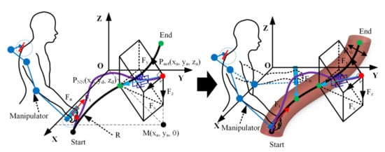
Figure 5.
Schematic diagram of enhancing the spatial virtual fault-tolerant region.
For an arbitrary trajectory , and are assumed to be the starting and ending points of the trajectory, respectively, and a cylindrical virtual channel with an adjustable radius is added around the trajectory. To better express the schematic of the FTR, it is simplified to a planar case, as shown in Figure 6. According to Equation (9), the magnitude and direction of the assistance force provided by the robot are related to the reference position during the rehabilitation training. Since the position of the patient’s hand is time-varying, a searching algorithm is needed to define the real-time reference position of the patient’s hand. First, the point that is nearest to the actual position of the patient’s arm on the training trajectory is solved:
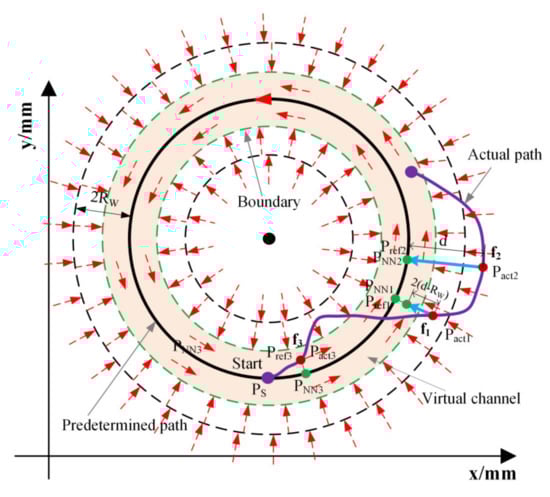
Figure 6.
The concept of the FTR (simplified to a planar circular case) in the assist-as-needed (AAN) controller.
A region with the width is then defined around the FTR to better define the reference position during the training. Firstly, the reference position was defined based on the distance between actual position of patient’s hand and the nearest point on predetermined trajectory:
As shown in Figure 6, the red dashed line is the boundary of the FTR. When the patient’s arm is moving inside the FTR, the reference point at this time is the actual point itself—for example, the point in Figure 6. When the patient’s hand deviates from the FTR but does not exceed , the reference point is calculated by Equation (12), such as the point in Figure 6. When the deviation of the patient’s arm from the FTR exceeds the radius , the reference point at this time is the nearest point on the predetermined trajectory, such as the point in Figure 6. Finally, when the patient’s hand is at the end of the trajectory , the reference point is the endpoint of the trajectory, such as the point in Figure 6. For any trajectory , the distance between current position and the nearest position should be greater than the radius of curvature of on the trajectory:
where is the curvature radius and is the point reachable by the manipulator.
After defining the reference point , the distance is solved to judge if the patient’s hand deviates from the predetermined trajectory or not, which is used to approximately evaluate the patient’s upper limb functional ability. The distance between the actual position of the hand and the reference position is used to calculate the time-varied assistance force provided by the robot:
According to Equation (9), an assistance force field distributed around the FTR is:
where is the assistance force and is the stiffness for the FTR.
According to the distance by which the patient deviates from the predetermined trajectory, the controller in reference [43] constructs a rigid wall with fixed stiffness to assist the patient’s arm by controlling the robot. In the controller proposed in this paper, the concept of the stiffness field is proposed and then the stiffness field is constructed within the scope of the width around the FTR. Assuming that the gradient of the stiffness field is , a series of columnar virtual stiffness walls are constructed. For example, the thin black solid line and the thick black solid line outside FTR in Figure 6; the thicker the line, the greater the stiffness of the wall. When the patient’s arm deviates from the FTR, a series of stiffness walls generated by the robot would provide a corresponding assistance force according to the patient’s functional ability. The greater the deviation of the patient’s hand, the greater the hardness of the stiffness wall, which could further improve the assistance effect of the manipulator. The stiffness of these columnar walls can be solved based on the position of the patient’s arm according to Equations (17) and (18):
where is the gradient of the stiffness field; is the stiffness inside the FTR; and are the upper and lower limits that could be changed according to the training tasks, respectively. Therefore, various stiffness fields can be constructed by changing and . According to Equations (9)–(18), a spatial assistance force field could be constructed during the rehabilitation training, and different intensities and distributions of the force field can be realized by adjusting the parameters of the controller. Therefore, the assistance force filed in Equation (15) can be rewritten as follows:
As a band-based FTR is provided in the controller, the patient has complete freedom when moving within the FTR, and the robot is in a complete compliant state without providing any assistance force. The purpose of the AAN controller is to improve the patient’s active participation and minimize the assistance of the robot. However, patients are prone to slacking because they only need to keep their arm within the FTR rather than try to complete the training task, which will greatly reduce the active participation of patients. Therefore, a velocity curve could be added in the FTR which will construct a virtual movement within the FTR. When the patient’s arm is stagnant or moving too slowly in the FTR, the controller will generate a moving wall to assist the patient’s arm to catch up with the virtual movement to avoid slacking. The assistance force is a fixed value along the direction of the training task trajectory within the FTR, which can be calculated by the following equations:
where is the assistance factor that can be adjusted by the therapist and is the tangent direction along the predetermined trajectory. Therefore, the total assistance force output by the AAN controller proposed in this paper is the superposition of the rectifying force outside the FTR and the fixed assistance force within the FTR. Then, the torque at each joint of the manipulator can be calculated according to Equation (3):
Therefore, once given the arbitrary training trajectory , a controllable assistance force field around the predetermined trajectory will be constructed. The distribution diagram of the assistance force field is shown in Figure 7a,b.
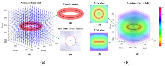
Figure 7.
The schematic diagram of the assistance force field with the FTR (take a circular trajectory as an example). (a) is the schematic diagram of the assistance force field; (b) is the distribution of the assistance force field.
The simplified control flow chart of the AAN controller proposed in this paper is shown in Figure 8. The right side of the flow chart is the joint torque caused by the interaction force between the patient’s hand and the robot, and is the dynamic model of the manipulator, which contains the Gravity term, the Coriolis force term, and the Friction term of the manipulator. The output item on the right side of the flow chart can be measured by the position sensor at each joint of the manipulator, and then, the actual position of the patient’s hand can be calculated based on the kinematic equation of the robot that is presented in Section 2. The left side of the flow chart is the input parameters of the AAN controller. The actual position of the patient’s hand is sent to the Set Point Generation module, and the output is the actual position of the patient’s hand and the real-time reference position. The real-time reference position and the actual position during the training are sent to the visual interface and the rehabilitation training scene based on Unity technology to visualize the patient’s movement. Besides, the visual interface also defines the training trajectory through the given starting and ending points of the trajectory, the point cloud data between the starting and ending points, and the reference position of the patient’s hand during the rehabilitation training. A traversal search algorithm is used to calculate the point on the trajectory that is nearest to the actual position of the patient’s upper limb. Meanwhile, the visual interface also provides the radius of the FTR, the gradient of the stiffness field, and the velocity curve within the FTR. This information is used as the input of the AAN controller. According to Equations (19), (21), and (22), the necessary time-varied assistance force provided by the robot can be calculated. The Jacobian matrix transpose is applied to solve the joint torque provided by the robot according to the AAN controller.
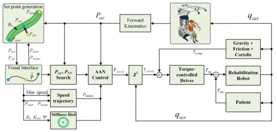
Figure 8.
The diagram control scheme of the proposed assist-as-needed controller.
3.2. Rehabilitation Training Mode of the Controller
According to the analysis in Section 3 (A), the parameters of the proposed AAN controller contain the radius of the virtual channel of the FTR , the upper and lower limits of the stiffness field and , the assistance factor , and the stiffness inside the FTR , which can make the controller show different performances by adjusting these parameters. Different controller parameters could satisfy the training requirement of patients at different rehabilitation stages. There are four rehabilitation training modes that could be realized through configuration and combination of those parameters above, namely passive rehabilitation training, assistant rehabilitation training, active rehabilitation training, and resistant rehabilitation training. The specific controller parameters of those training modes are shown in Table 1.

Table 1.
The controller parameters of different rehabilitation training modes.
As can be seen from Table 1, the robot moves with a high stiffness value with no fault tolerance without considering the participation of the patient in the passive training mode. The robot moves the patient’s arm to finish the training tasks on a fixed trajectory, which is suitable for patients in the early recovery stage. The controller provides a virtual FTR in the assistant training mode. The patient has complete freedom within the FTR and the robot does not provide any assistance force, while the controller will generate a series of columnar stiffness walls to provide the time-varied assistance force according to the patient’s functional ability when deviating from the FTR. It is suitable for patients with partial control ability of the upper limb in the middle and late rehabilitation stages. The radius of the FTR is infinite and the stiffness of the virtual stiffness wall is zero in the active training mode. The robot is in a completely compliant and backward-driven state and the patient has complete freedom. It is suitable for patients who have a certain upper limb motor ability and need to conduct movement stability training at the later rehabilitation stage. The controller has the characteristic of obstructing the patient’s movement in the resistant training mode, and it requires a certain amount of strength for the patients to overcome the obstacles to finish the rehabilitation task. It is suitable for patients in the later rehabilitation stage and patients who need to further strengthen their muscle force.
4. Validation Experiments and Results
This section mainly provides experiments under four different conditions to illustrate the correctness of the controller proposed in this paper for passive, assistant, active, and resistant robot-aided rehabilitation training for patients with an upper extremity motor dysfunction. There are five parameters of the proposed controller that need to be adjusted during the testing. The experiments were conducted on the end-effector rehabilitation robot designed in Section 2. The purpose of the experiments was to verify the function of the controller proposed in this paper. The experiments were not clinical experiments or patient-based experiments but merely healthy volunteer-based experiments to demonstrate the functionality and usability of the proposed AAN controller with different parameters. The participant was a healthy elderly female aged 65, 165 cm in height, and 55 kg in weight, and we assumed that the subject’s right arm was the affected side. The manipulator on the opposite side was moved to a safe position that was defined in advance, so as not to affect the testing. The subject was required to complete a rehabilitation training task on a circle trajectory under different controller parameters with relatively slow velocity. A visual scene developed based on the Unity technology was provided for the subject, which was displayed on a screen in front of the subject. A screenshot of the visual scene is shown in Figure 9, and two flat plane views are adopted to represent the three-dimensional trajectory and the FTR. The yellow curve in Figure 9 is the training trajectory, the gray curve is the inner and outer boundaries of the FTR with adjustable radius, and the white ball is for the actual position of the patient’s arm. Besides, the red arrow is the indication of the assistance force provided by the robot, and the longer the arrow is, the greater the assistance force provided by the robot. Since we paid more attention to the position of subject’s hand, the pose of the robot’s handle was fixed during the testing, as shown in Figure 10a.
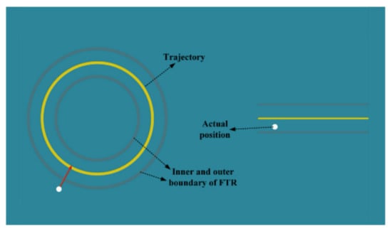
Figure 9.
The screenshot of the Unity scene for the testing.
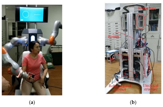
Figure 10.
The subject testing and the detail structure of the rehabilitation robot. (a) The experimental testing with the subject and (b) the internal structure of the rehabilitation robot prototype.
The internal structure of the rehabilitation robot prototype that was used for experimental testing is shown in Figure 10b. The controller cabinets of two manipulators were connected to a router and then connected to the control computer. Manipulators were installed on two perpendicular planes, as seen in Figure 10b. The commercial manipulator can conduct real-time external torque control through the robot software package FRI [44] with the following control law:
where is the joint stiffness matrix of manipulator; is the damping term, and is the dynamic term of the manipulator. Besides, is the expected torque, which is the assistance force calculated by Equation (22). The data of robot were received and sent by TCP/IP (Transmission Control Protocol / Internet Protocol) during the experiments, and the joint position of the robot was measured by a position sensor at each joint of the manipulator. The interaction force between the robot and the patient’s hand can be calculated by the torque measured through the torque sensor at each joint:
where is the Jacobian pseudo-inverse matrix and . The joint position and joint torque were dealt with by using a Gaussian lowpass filter to reduce the influence of noise. To further evaluate the functional ability of the subject’s arm, the distance between the actual and expected trajectories was calculated according to Equation (25):
where is the calculated distance. The total interaction force between the robot’s handle and the subject’s hand is calculated as follows:
4.1. Validation Experiment of Passive Rehabilitation Training Mode of the Controller
Passive training is mainly used in the early rehabilitation stage for patients with motor dysfunction. The patient does not have motor ability and the robot dominates the whole rehabilitation training process. The robot drives the patient’s arm to accurately track the rehabilitation trajectory. The subject’s arm was fixed by a bandage to the handle, and the subject was required to be relaxed during the passive training testing; then, the subject’s arm was guided by the robot to perform rehabilitation training on the circle trajectory. The testing tasks were performed, and the moving direction was counterclockwise with three turns. The Unity scene provides the subject with visual guidance and records the number of turns of movement. The parameters of the controller were = 0 mm, = [5000, 5000, 5000] N/m, = [5000, 5000, 5000] N/m, = [5000, 5000, 5000] N/m, and = [5000, 5000, 5000] N/m.
Figure 11 shows the trajectory of the subject’s arm, in which the blue curve is the actual trajectory of the patient’s hand and the black curve is the predetermined trajectory. Figure 12 shows the filtered interaction force and wrench between the robot and the subject’s hand, and Figure 13 shows the filtered deviation between the subject’s trajectory and the predetermined trajectory, as well as the total interactive force between the subject’s hand and the handle. As can be seen from the experimental results, the robot guided the subject’s hand to move along the predetermined trajectory accurately, and the root mean square (RMS) of the deviation between the actual trajectory of the subject’s hand and the predetermined trajectory is 2.44 mm. The RMS of the interaction force between the subject’s hand and the robot is 11.14 N, as shown in Figure 12a. In addition, the RMS of the interaction wrench between the subject’s hand and the handle is 2.24 Nm, owing to the fixed robot pose. The results in Figure 13 show that the deviation of the subject’s hand is quite small, which means the robot could drive the subject’s hand to track the predetermined trajectory accurately.
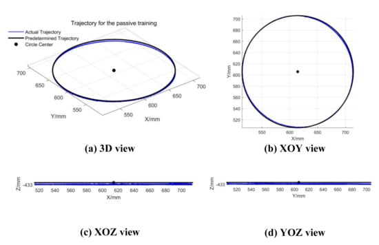
Figure 11.
The trajectory of the subject’s arm during the passive testing. (a) Three-dimensional view of the trajectory; (b–d) XOY, XOZ, and YOZ view of the trajectory, respectively.
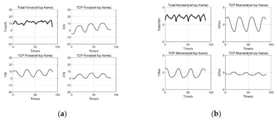
Figure 12.
The interaction force and moment between the handle and the subject’s hand. (a) is the interaction force between the handle and subject’s hand; (b) is the moment between the handle and subject’s hand.
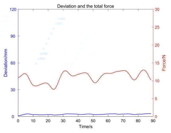
Figure 13.
The total interaction force and the deviation between the handle and the subject’s hand.
4.2. Validation Experiment of Assistant Rehabilitation Training Mode of the Controller
The AAN assistant training is applicable to patients with certain control ability of their upper arm. When the patient’s motor ability is better (moving in the FTR), the robot does not provide any assistance to the patient’s movement. Conversely, the robot would provide corresponding assistance force according to the patient’s functional ability to assist the patient’s arm to finish the training task. The controller will show AAN characteristics as long as the parameters of the controller are properly adjusted. In order to illustrate the AAN characteristics of the controller, the parameters of the controller were set as = 25 mm, = [300, 300, 300] N/m, = [500, 500, 500] N/m, = [500, 500, 500] N/m, and = [10, 10, 10] N/m. The pose of the robot was fixed during the test, and a total of seven turns of counterclockwise movement were tested. In the first three laps, the subject was required to be relaxed, and the moving wall within the controller would push the patient’s arm to catch up with the virtual movement to complete the training task. In the following three laps, the subject takes the initiative to complete the exercise. In the last lap, the subject was required to deliberately deviate from the FTR to test and verify the variation trend of the assistance force provided by the robot. The Unity scene provided the subject with visual guidance and recorded the number of laps of the movement during the testing.
Figure 14 shows the trajectory of the subject’s arm and the training trajectory, in which the blue curve is the actual trajectory of the subject’s arm, the black curve is the desired trajectory, and the red channel is for the virtual FTR. Figure 15 shows the filtered interaction force and wrench between the subject’s hand and the handle. Figure 16 shows the filtered distance between the subject’s hand and the training trajectory, as well as the total interactive force between the subject’s hand and the handle. In the first three laps, the subject was required to be relaxed, and her movement lagged behind the virtual movement in the FTR (considered as slacking occurred). Therefore, the robot would generate a moving wall to assist the subject to catch up with the virtual movement. It can be seen from Figure 14c,d that the trajectory of the subject’s hand is below the predetermined trajectory due to the influence of the weight of the subject’s arm. It can be seen from Figure 15a that the RMS of the total interaction force between the subject’s hand and the handle is 10.2 N, which is mainly caused by the weight of the arm. In the following three laps, the subject was required to be active and the moving trajectory mainly concentrated within the FTR. One can conclude from Figure 16 that the deviation between the actual trajectory and the predetermined trajectory of the subject’s hand was smaller than that of the first three laps obviously. The RMS of the total interactive force between the subject’s hand and the handle is 2.01 N, as shown in Figure 15a, which is mainly caused by the motion speed and the error of the torque sensor. During the last lap, it can be seen from Figure 14c,d that the trajectory of the subject’s hand intentionally deviated from FTR significantly. Figure 15a shows that the robot will provide assistance when the subject’s arm deviates from the FTR. The greater the degree of deviation, the stiffer the stiffness wall will be and the greater the assistance force will be. It can be seen from Figure 16 that when the subject’s arm moves in the FTR, the robot does not provide assistance force, while the robot will provide corresponding assistance force according to the deviation degree when deviating from the FTR. Since the robot’s pose remained fixed during the testing, the RMS of the interactive wrench is 2.05 Nm, as shown in Figure 15b.
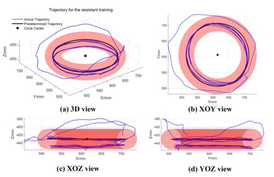
Figure 14.
The trajectory of the subject’s hand during the assistant testing. (a) A 3D view of the trajectory; (b–d) XOY, XOZ, and YOZ view of the trajectory, respectively.
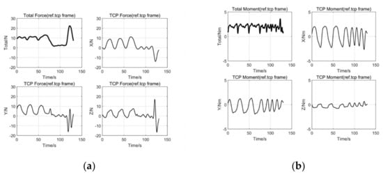
Figure 15.
The interaction force and moment between the handle and the subject’s hand. (a) is the interaction force between the handle and subject’s hand; (b) is the moment between the handle and subject’s hand.
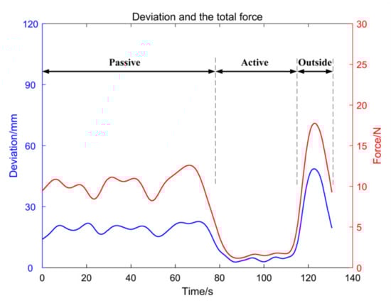
Figure 16.
The total interaction force and the deviation between the handle and the subject’s hand.
In order to verify the correctness of the controller that can be used for assistant training, the parameters of the controller were set as the values in the experiment. In fact, different parameters such as the size of the FTR, the assistance factor, and the distribution of the stiffness field can be adjusted according to the patient’s actual functional ability by the therapists.
4.3. Validation Experiment of Active Rehabilitation Training Mode of the Controller
For those patients who already have regained motor control ability of the upper limb, they could move their arm; however, stability training of their arm is needed. The robot could be in a completely backward-driven state by adjusting the parameters of the controller proposed in this paper, and the patient can move the robot on any trajectory without any assistance force from the robot. The subject was required to complete the predetermined circular trajectory during the test, moving counterclockwise for a total of three turns. Similarly, the pose of the robot remained fixed during the testing, and the parameters of the controller was set as is infinite, = [0, 0, 0] N/m, = [0, 0, 0] N/m, = [500, 500, 500] N/m, and = [0, 0, 0] N/m. Figure 17 shows the actual and training trajectories of the subject’s arm. Figure 18 presents the filtered interaction force and wrench between the subject’s hand and the handle. Figure 19 shows the filtered total force between the subject’s hand and the handle as well as the deviation between the actual trajectory and the predetermined trajectory.
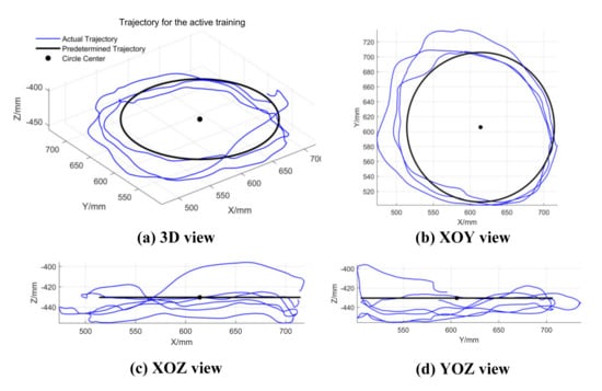
Figure 17.
The trajectory of the subject’s hand during the active testing. (a) A 3D view of the trajectory; (b–d) XOY, XOZ, and YOZ view of the trajectory, respectively.
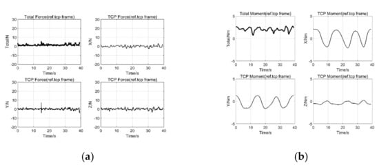
Figure 18.
The interaction force and moment between the handle and the subject’s hand. (a) is the interaction force between the handle and subject’s hand; (b) is the moment between the handle and subject’s hand.
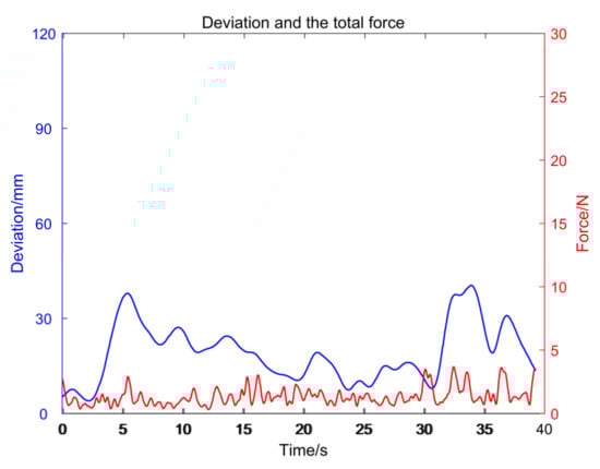
Figure 19.
The total interaction force and the deviation between the handle and the subject’s hand.
As can be seen from Figure 17, the deviation between the subject’s trajectory and the predetermined trajectory is relatively large, with the maximum value being 40.43 mm. It can be seen from Figure 18a that the RMS of the total interaction force between the subject’s hand and the handle is 1.66 N. As the robot’s pose remained fixed during the testing, it can be seen from Figure 18b that the RMS of the interactive wrench is 2.08 Nm. One can conclude that the robot does not provide any assistance force in the active rehabilitation training mode, so the subject can move freely and be allowed to choose his own trajectory. Therefore, active rehabilitation training can be performed under the guidance of a Unity scene.
4.4. Validation Experiment of Resistant Rehabilitation Training Mode of the Controller
For patients who have recovered their motor ability in the later rehabilitation stage, the strength of the main muscle groups of the arm is relatively weak. Therefore, resistant rehabilitation training is required for these patients to further strengthen their muscle force. To illustrate that the controller proposed in this paper can be applied to resistant rehabilitation training by adjusting the parameters, the parameters of the controller were set as = 25 mm, = [300, 300, 300] N/m, = [500, 500, 500] N/m, = [500, 500, 500] N/m, and = [500, 500, 500] N/m during the experimental testing. The robot’s pose remained fixed during the testing, and the subject was required to complete three laps in counterclockwise direction under the guidance of the Unity scene. Figure 20, Figure 21 and Figure 22 present the actual and predetermined trajectories of the subject’s arm, the filtered interaction force and torque between the subject’s arm and the handle, and the filtered total interaction force between the subject’s arm and handle as well as the deviation between the actual and predetermined trajectories, respectively.
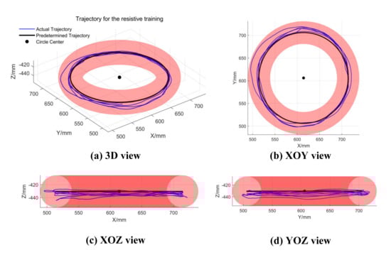
Figure 20.
The trajectory of subject’s hand during the resistant testing. (a) A 3D view of the trajectory; (b–d) XOY, XOZ, and YOZ view of the trajectory, respectively.
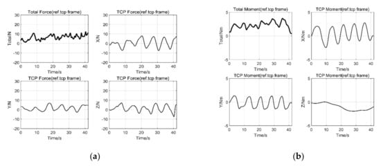
Figure 21.
The interaction force and moment between the handle and the subject’s hand. (a) is the interaction force between the handle and subject’s hand; (b) is the moment between the handle and subject’s hand.
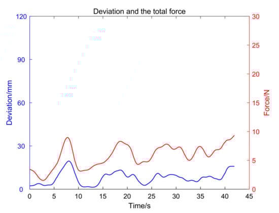
Figure 22.
The total interaction force and the deviation between the handle and the subject’s hand.
It can be seen from the experimental results that the trajectory of subject’s arm was mainly inside the FTR, as shown in Figure 20. However, the interaction force between the subject’s arm and the robot was relatively large, as shown in Figure 21a. Although the subject was moving within the FTR, the controller parameter was set as a constant value to create a resistance force that prevents the subject from moving. Therefore, the subject had to overcome the resistance before they could move their arm actively. To a certain extent, the upper limb muscle groups of patients could be strengthened by resistant rehabilitation training, and resistance training of different intensities can be achieved by adjusting the parameter . With the increase in , the intensity of the resistance training increases. One can conclude from the experimental results that the performance of the controller could be useful to train a participant’s upper limb muscle strength at different intensities by adjusting the values of controller parameters.
5. Discussion and Conclusions
In this paper, an impedance-based AAN controller for robot-aided rehabilitation training is proposed to provide training for all rehabilitation stages of upper limb and has been realized on an end-effector rehabilitation robot that was constructed by two commercial manipulators. The controller proposed in this work enables a subject’s arm to have motion freedom within the FTR constructed around the predetermined training trajectory and provides as much assistance as needed when the patient is in need of help. Meanwhile, when patients are deviating from the FTR, the concept of the stiffness field is also proposed around the FTR to assist the patient’s arm according to their functional ability. Furthermore, the controller contains five adjustable parameters: the radius of the FTR, the upper and lower limits and of the stiffness field, the assistance factor of the assistance wall to prevent slacking, and the stiffness inside the FTR . By adjusting these controller parameters, the AAN controller proposed in this paper could perform rehabilitation training of the passive mode, assistant mode, active mode, and resistant mode. Finally, the performance of the controller under different parameters was verified by experimental testing with a healthy elderly subject.
Among the tests, the robot could accurately track the predetermined rehabilitation trajectory when the controller was activated in the passive training mode. When the controller was activated in the assistant training mode, the controller showed the AAN characteristic. The controller enabled the patient’s arm to move freely in the allowed FTR, while the robot generated a series of columnar virtual stiffness walls according to the patient’s functional ability to provide assistance when deviating from the FTR. Once slacking occurred in the patient, the moving assistance wall inside the FTR assisted the patient’s arm to catch up with the virtual movement. Then, the robot would be in a completely backward-driven state when the controller is activated in the active training mode, and the patient has complete freedom, which can be used for stability training in the later rehabilitation stage. Finally, the controller could create a resistance force that hinders the patient’s movement when activated in the resistant training mode. Therefore, the patient needed to overcome this obstacle to finish the training task, which can be used to train a participant’s upper limb muscle strength. The preliminary experimental results under different training modes show the correctness of the controller proposed in this paper and the potential ability of providing passive, assistant, active, and resistant training modes by adjusting several controller parameters, which covers all rehabilitation stages of the upper limb. We expect that the impedance-based AAN controller proposed in this paper could be extended to develop similar controllers for the multi-DOF exoskeleton rehabilitation robot or bilateral rehabilitation robots.
As a prospective study, only one healthy elderly subject was tested in this paper to validate the correctness of the proposed impedance-based AAN controller in passive, assistant, active, and resistant rehabilitation training modes. Nonetheless, the effectiveness of the proposed controller for patients with upper limb motor dysfunction needs to be validated through clinical studies in future work. In the next step, the controller with different rehabilitation training modes is planned to be applied on more subjects and also patients to demonstrate the performance of the controller with different parameters and to help to increase the training intensity.
Author Contributions
In this work, L.Z. conceived, designed, and performed the experiments and wrote the paper; S.G. guided the writing of the article and gave some suggestions; L.Z. and Q.S. analyzed the data. All authors have read and agreed to the published version of the manuscript.
Funding
This research was supported by the National Natural Science Foundation of China (Grant No. 61973205) and the National Key Research and Development Program of China (Grant No. 2018YFC2001601).
Institutional Review Board Statement
Ethical review and approval were waived for this study, due to the fact that we are simply to illustrate and evaluate the function of our proposed control strategy and the method with a volunteer subject testing. In other words, we were used a test case/example to evaluate the performance of the controller proposed in our study.
Informed Consent Statement
Informed consent was obtained from all subjects (one subject in this study) involved in the study.
Data Availability Statement
The data presented in this study are available in Supplementary Material.
Acknowledgments
The authors are grateful to anonymous reviewers and the Editor for their comments and suggestions on improving our manuscript.
Conflicts of Interest
The authors declare no conflict of interest.
References
- Malcolm, M.P.; Massie, C.; Thaut, M. Rhythmic Auditory-Motor Entrainment Improves Hemiparetic Arm Kinematics During Reaching Movements: A Pilot Study. Top. Stroke Rehabil. 2009, 16, 69–79. [Google Scholar] [CrossRef] [PubMed]
- Cortese, M.; Cempini, M.; Rogerio, D.A.R.P.; Soekadar, S.R.; Carrozza, M.C.; Vitiello, N. A Mechatronic System for Robot-Mediated Hand Telerehabilitation. IEEE/ASME Trans. Mechatron. 2015, 20, 1753–1764. [Google Scholar] [CrossRef]
- Milot, M.; Spencer, S.J.; Chan, V.; Allington, J.P.; Klein, J.; Chou, C.; Bobrow, J.E.; Cramer, S.C.; Reinkensmeyer, D.J. A crossover pilot study evaluating the functional outcomes of two different types of robotic movement training in chronic stroke survivors using the arm exoskeleton BONES. J. Neuroeng. Rehabil. 2013, 10, 112. [Google Scholar] [CrossRef] [PubMed]
- Mehrholz, J.; Hädrich, A.; Platz, T.; Kugler, J.; Pohl, M. Electromechanical and robot-assisted arm training for improving generic activities of daily living, arm function, and arm muscle strength after stroke. Cochrane Database Syst. Rev. 2012, CD006876. [Google Scholar] [CrossRef]
- Roger, G.; Volker, D. Rehabilitation robots for the treatment of sensorimotor deficits: A neurophysiological perspective. J. Neuroeng. Rehabil. 2018, 15, 46. [Google Scholar]
- Krebs, H.I.; Ferraro, M.; Buerger, S.P.; Newbery, M.J.; Makiyama, A.; Sandmann, M.; Lynch, D.; Volpe, B.T.; Hogan, N. Rehabilitation robotics: Pilot trial of a spatial extension for MIT-Manus. J. Neuroeng. Rehabil. 2004, 1, 5. [Google Scholar] [CrossRef] [PubMed]
- Rui, L.; Amirabdollahian, F.; Topping, M.; Driessen, B.; Harwin, W. Upper Limb Robot Mediated Stroke Therapy—GENTLE/s Approach. Auton. Robot. 2003, 15, 35–51. [Google Scholar]
- Nef, T.; Guidali, M.; Riener, R. ARMin III—Arm therapy exoskeleton with an ergonomic shoulder actuation. Appl. Bionics Biomech. 2009, 6, 127–142. [Google Scholar] [CrossRef]
- Sugar, T.G.; He, J.; Koeneman, E.J.; Koeneman, J.B.; Herman, R.; Huang, H.; Schultz, R.S.; Herring, D.E.; Wanberg, J.; Balasubramanian, S. Design and control of RUPERT: A device for robotic upper extremity repetitive therapy. IEEE Trans. Neural Syst. Rehabil. Eng. 2007, 15, 336–346. [Google Scholar] [CrossRef]
- Akiyama, Y.; Yamada, Y.; Okamoto, S. Interaction forces beneath cuffs of physical assistant robots and their motion-based estimation. Adv. Robot. 2015, 29, 15. [Google Scholar] [CrossRef]
- Chang, W.H.; Kim, Y.H. Robot-assisted Therapy in Stroke Rehabilitation. J. Stroke 2013, 15, 174–181. [Google Scholar] [CrossRef] [PubMed]
- Lee, S.; Park, G.; Cho, D.; Kim, H.; Lee, J.; Suyoung, K.; Park, S.; Shin, J. Comparisons between end-effector and exoskeleton rehabilitation robots regarding upper extremity function among chronic stroke patients with moderate-to-severe upper limb impairment. Sci. Rep.-UK 2020, 10, 1806. [Google Scholar] [CrossRef] [PubMed]
- Warraich, Z.; Kleim, J. Neural Plasticity: The Biological Substrate for Neurorehabilitation. PM R J. Inj. Funct. Rehabil. 2010, 2, S208–S219. [Google Scholar] [CrossRef] [PubMed]
- Wolbrecht, E.T.; Chan, V.; Reinkensmeyer, D.J.; Bobrow, J.E. Optimizing Compliant, Model-Based Robotic Assistance to Promote Neurorehabilitation. IEEE Trans. Neural Syst. Rehabil. Eng. 2008, 16, 286–297. [Google Scholar] [CrossRef]
- Claude, L.; Moreno, J.C.; Luis, P.J. Human-robot interfaces in exoskeletons for gait training after stroke: State of the art and challenges. Appl. Bionics Biomech. 2014, 9, 193–203. [Google Scholar]
- Duschau-Wicke, A.; Caprez, A.; Riener, R. Patient-cooperative control increases active participation of individuals with SCI during robot-aided gait training. J. Neuroeng. Rehabil. 2010, 7, 43. [Google Scholar] [CrossRef]
- Agarwal, P.; Fernandez, B.R.; Deshpande, A.D. Assist-as-Needed Controllers for Index Finger Module of a Hand Exoskeleton for Rehabilitation. In Proceedings of the ASME 2015 Dynamic Systems and Control Conference, Columbus, OH, USA, 28–30 October 2015. [Google Scholar]
- Pehlivan, A.; Sergi, F.; O’Malley, M. A Subject-Adaptive Controller for Wrist Robotic Rehabilitation. IEEE/ASME Trans. Mechatron. 2014, 20, 1338–1350. [Google Scholar] [CrossRef]
- Grosmaire, A.G.; Duret, C. Does assist-as-needed upper limb robotic therapy promote participation in repetitive activity-based motor training in sub-acute stroke patients with severe paresis? Neurorehabilitation 2017, 41, 31–39. [Google Scholar] [CrossRef]
- Hogan, N. Impedance Control: An Approach to Manipulation: Part III—Applications. Asme J. Dyn. Syst. Meas. Control 1985, 107, 481–489. [Google Scholar] [CrossRef]
- Guidali, M.; Duschau-Wicke, A.; Broggi, S.; Klamroth-Marganska, V.; Nef, T.; Riener, R. A robotic system to train activities of daily living in a virtual environment. Med. Biol. Eng. Comput. 2011, 49, 1213–1223. [Google Scholar] [CrossRef]
- Klamroth-Marganska, V.; Blanco, J.; Campen, K.; Curt, A.; Dietz, V.; Ettlin, T.; Felder, M.; Fellinghauer, B.; Kollmar, A.; Luft, A.; et al. Three-dimensional, task-specific robot therapy of the arm after stroke: A multicentre, parallel-group randomised trial. Lancet Neurol. 2013, 13, 159–166. [Google Scholar] [CrossRef]
- Krebs, H.I.; Palazzolo, J.J.; Dipietro, L.; Ferraro, M.; Krol, J.; Rannekleiv, K.; Volpe, B.T.; Hogan, N. Rehabilitation Robotics: Performance-Based Progressive Robot-Assisted Therapy. Auton. Robot. 2003, 15, 7–20. [Google Scholar] [CrossRef]
- Krebs, H.; Volpe, B.; Williams, D.; Celestino, J.; Charles, S.; Lynch, D.; Hogan, N. Robot-Aided Neurorehabilitation: A Robot for Wrist Rehabilitation. IEEE Trans. Neural Syst. Rehabil. Eng. 2007, 15, 327–335. [Google Scholar] [CrossRef] [PubMed]
- Hogan, N.; Krebs, H.I.; Rohrer, B.; Palazzolo, J.J.; Dipietro, L.; Fasoli, S.E.; Stein, J.; Hughes, R.; Frontera, W.R.; Lynch, D. Motions or muscles? Some behavioral factors underlying robotic assistance of motor recovery. J. Rehabil. Res. Dev. 2006, 43, 605. [Google Scholar] [CrossRef] [PubMed]
- Wu, Q.; Chen, B.; Wu, H. Adaptive Admittance Control of an Upper Extremity Rehabilitation Robot with Neural-Network-Based Disturbance Observer. IEEE Access 2019, 7, 123807–123819. [Google Scholar] [CrossRef]
- Jabbari Asl, H.; Narikiyo, T.; Kawanishi, M. An assist-as-needed control scheme for robot-assisted rehabilitation. In Proceedings of the 2017 American Control Conference (ACC), Seattle, WA, USA, 24–26 May 2017; pp. 198–203. [Google Scholar]
- Cui, X.; Chen, W.; Jin, X.; Agrawal, S.K. Design of a 7-DOF Cable-Driven Arm Exoskeleton (CAREX-7) and a Controller for Dexterous Motion Training or Assistance. IEEE/ASME Trans. Mechatron. 2017, 22, 161–172. [Google Scholar] [CrossRef]
- Asl, H.J.; Yamashita, M.; Narikiyo, T.; Kawanishi, M. Field-Based Assist-As-Needed Control Schemes for Rehabilitation Robots. IEEE/ASME Trans. Mechatron. 2020, 25, 2100–2111. [Google Scholar] [CrossRef]
- Casadio, M.; Sanguineti, V. Learning, Retention, and Slacking: A Model of the Dynamics of Recovery in Robot Therapy. IEEE Trans. Neural Syst. Rehabil. Eng. 2012, 20, 286–296. [Google Scholar] [CrossRef]
- Teramae, T.; Noda, T.; Morimoto, J. EMG-Based Model Predictive Control for Physical Human–Robot Interaction: Application for Assist-As-Needed Control. IEEE Robot. Autom. Lett. 2017, 3, 210–217. [Google Scholar] [CrossRef]
- Andel, C.; Wolterbeek, N.; Doorenbosch, C.; Veeger, D.; Harlaar, J. Complete 3D Kinematics of upper extremity functional tasks. Gait Posture 2008, 27, 120–127. [Google Scholar] [CrossRef]
- Pehlivan, A.; Losey, D.; O’Malley, M. Minimal assist-as-needed (mAAN) controller for upper limb robotic rehabilitation. IEEE Trans. Robot. 2016, 32, 113–124. [Google Scholar] [CrossRef]
- Pérez-Rodríguez, R.; Rodriguez-Guerrero, C.; Costa, U.; Caceres, C.; Tormos, J.; Medina, J.; Gómez Aguilera, E. Anticipatory assistance-as-needed control algorithm for a multijoint upper limb robotic orthosis in physical neurorehabilitation. Expert Syst. Appl. 2013, 41, 3922–3934. [Google Scholar] [CrossRef]
- Vergaro, E.; Casadio, M.; Squeri, V.; Giannoni, P.; Morasso, P.; Sanguineti, V. Self-adaptive robot training of stroke survivors for continuous tracking movements. J. Neuroeng. Rehabil. 2010, 7, 13. [Google Scholar] [CrossRef] [PubMed][Green Version]
- Mancisidor, A.; Zubizarreta, A.; Cabanes, I.; Bengoa, P.; Brull, A.; Jung, J.H. Inclusive and seamless control framework for safe robot-mediated therapy for upper limbs rehabilitation. Mechatronics 2019, 58, 70–79. [Google Scholar] [CrossRef]
- Chen, C.; Wang, P.; Wang, H.; Chen, C.C. Developing industrial dual arm robot for flexible assembly through reachability map. Tech. Rep. 2015. [Google Scholar] [CrossRef]
- Zhang, L.; Guo, S.; Huang, Y.; Xiong, X. Kinematic Singularity Analysis and Simulation for 7dof Anthropomorphic Manipulator. Int. J. Mechatron. Appl. Mech. 2019, I, 157–164. [Google Scholar]
- Zhang, L.; Guo, S.; Sun, Q. Development and Assist-as-Needed Control of an End-Effector Upper Limb Rehabilitation Robot. Appl. Sci. 2020, 19, 6684. [Google Scholar] [CrossRef]
- Costa, J.M.S.D.; Martins, J.M. Dynamic Modelling of the Compliant KUKA-DLR Lightweight Robot; University of Lisbon: Lisboa, Portugal, 2014. [Google Scholar]
- Rodrigues, T.A.; Goroso, D.G.; Westgate, P.M.; Carrico, C.; Batistella, L.R.; Sawaki, L. Slow versus Fast Robot-Assisted Locomotor Training after Severe Stroke. Am. J. Phys. Med. Rehabil. 2017, 96, S165–S170. [Google Scholar] [CrossRef]
- Hui, G.; Misgeld, B.J.E.; Shi, Y.; Ji, L. Dynamic Modeling and Interactive Performance of PARM: A Parallel Upper-Limb Rehabilitation Robot Using Impedance Control for Patients after Stroke. J. Healthc. Eng. 2018, 2018, 8647591. [Google Scholar]
- Huo, J.; Zhang, X.; Ji, R.; Liu, Y.; Bi, S.; Ji, L.; Li, C. Development and Implementation of an End-Effector Upper Limb Rehabilitation Robot for Hemiplegic Patients with Line and Circle Tracking Training. J. Healthc. Eng. 2017, 2017, 4931217. [Google Scholar]
- Schreiber, G.; Stemmer, A.; Bischoff, R. In The Fast Research Interface for the KUKA Lightweight Robot. In Proceedings of the Workshop on IEEE ICRA Workshop on Innovative Robot Control Architectures for Demanding Applications—How to Modify & Enhance Commercial Controllers, Anchorage, AK, USA, 3–7 May 2010. [Google Scholar]
Publisher’s Note: MDPI stays neutral with regard to jurisdictional claims in published maps and institutional affiliations. |
© 2020 by the authors. Licensee MDPI, Basel, Switzerland. This article is an open access article distributed under the terms and conditions of the Creative Commons Attribution (CC BY) license (http://creativecommons.org/licenses/by/4.0/).