Article

Switched Control of Motor Assistance and Functional Electrical Stimulation for Biceps Curls †

Department of Mechanical Engineering, University of Florida, Gainesville, FL 32611, USA
*
Author to whom correspondence should be addressed.
Extended version of conference paper (Switched motorized assistance during switched functional electrical stimulation of the biceps brachii to compensate for fatigue).
Appl. Sci. 2020, 10(22), 8090; https://doi.org/10.3390/app10228090
Submission received: 15 October 2020 / Revised: 7 November 2020 / Accepted: 12 November 2020 / Published: 15 November 2020
(This article belongs to the Special Issue Robotic and Sensor Technology for Upper Limb Rehabilitation)

Abstract

:
Rehabilitation robotics is an emerging tool for motor recovery from various neurological impairments. However, balancing the human and robot contribution is an open problem. While the motor input can reduce fatigue, which is often a limiting factor of functional electrical stimulation (FES) exercises, too much assistance can slow progress. For a person with a neurological impairment, FES can assist by strategically contracting their muscle(s) to achieve a desired limb movement; however, feasibility can be limited due to factors such as subject comfort, muscle mass, unnatural muscle fiber recruitment, and stimulation saturation. Thus, motor assistance in addition to FES can be useful for prolonging exercise while still ensuring physical effort from the person. In this paper, FES is applied to the biceps brachii to perform biceps curls, and motor assistance is applied intermittently whenever the FES input reaches a pre-set comfort threshold. Exponential stability of the human–robot system is proven with a Lyapunov-like switched systems stability analysis. Experimental results from participants with neurological conditions demonstrate the feasibility and performance of the controller.

1. Introduction

Robot-assisted therapy has been shown to be beneficial for rehabilitation and neurological relearning for people with movement impairments. Specifically, in [1], robot-assisted therapy was used to aid in stroke recovery. More recently in [2], robot-assisted rehabilitation resulted in significant gains in motor impairment and functional recovery of the upper limb of acute stroke patients. The reviews in [3,4,5] compare various therapeutic robots that have been developed for the upper extremity. While exercises involving robotic assistance are advantageous for rehabilitation, intensive active involvement by the person (rather than only passive motion) is beneficial for motor recovery [6,7,8]. Balancing human and robot contributions often requires patient-specific adaptations of the controller [9]. Many methods have been used to facilitate maximal human contribution, such as challenge-based robots [10], assist-as-needed controllers [11,12], an adaptive algorithm based on lead/lag performance [13], and an algorithm for altering allowable error and decaying disturbance rejection [14].
Functional electrical stimulation (FES) is another rehabilitation tool that can be used alongside robot-assisted therapy. Used to elicit involuntary muscle contractions, FES is particularly useful for people with neurological disorders. For instance, FES has been found to increase strength in the biceps brachii [15] and motor function on the post-stroke paretic arm [16]; however, for people that have some sensory feedback intact, there is often discomfort at high levels of stimulation. Thus, stimulation often must be limited to levels below that necessary to perform certain exercises with muscle force alone. To compensate, it may be necessary to incorporate motor/robotic assistance. In [17], a combination of robotic assistance and FES resulted in arm mobility improvements in severely impaired stroke survivors. In this paper, we design an upper arm robot-assisted FES rehabilitiation device and protocol where the robot only assists when the necessary stimulation input reaches a saturation limit (e.g., due to a predefined comfort level by the participant).
This paper focuses on biceps curls since they are a common upper body exercise with a simple, one-degree-of-motion movement. Moreover, repetitive movements, such as biceps curls, are known to be beneficial for people with neurological conditions by improving coordination [3,18]. In [19], FES is used to induce biceps curls and motor assistance is provided intermittently whenever the stimulation reaches a pre-set comfort threshold; however, tracking performance may be further improved by extending bouts of motor assistance, during which stimulation is decreased (a byproduct of motor assistance decreasing the tracking errors), but the muscle is still activated and contracting. In this paper, and in [19,20], FES of the biceps brachii is used as the primary actuator for tracking a desired elbow angle trajectory that represents a biceps curl. Multiple electrodes (i.e., stimulation channels) are placed across the muscle, and the motor contributes when the stimulation threshold is reached; however, here, as in the preliminary works in [20], from which this paper builds upon, the motor will continue to contribute until the stimulation decays to a selected lower stimulation value, which prevents the FES control input from oscillating at the stimulation threshold and causing motor chatter. This novel approach eliminates the potential for motor chatter without the need to activate the motor throughout the entire biceps curl exercise, which may be too much assistance for the patient. Additionally, a strategy is developed to decrease the lower stimulation threshold throughout the biceps curl, such that the motor is active for longer as the person fatigues and/or performance decreases, yielding individualized adjustments. Switched sliding mode FES and motor controllers are developed and nonlinear control methods for switched systems are used to prove exponential stability by establishing a common Lyapunov function for all possible combinations of the actuators. Experiments on both arms of two participants with hemiparesis resulted in average root mean square (RMS) position errors of 4.55 degrees and 4.36 degrees for the impaired and unimpaired arms, respectively, which proves the feasibility of using the proposed combined FES-motor control system for biceps curls.

2. Materials and Methods

2.1. Dynamics

The dynamics of the human–robot system are
M q ¨ + V q ˙ + G + τ p + τ b + τ d = τ m + τ e ,
where q : R > 0 Q denotes the elbow joint angle, and Q 0 , π denotes the set of forearm angles. Full elbow extension is considered zero degrees and positive rotation is the direction in which the forearm is moving towards the biceps. The states q and q ˙ are assumed to be measurable and calculable, respectively. Inertial effects are denoted by M : Q R > 0 ; V : Q × R R denotes centripetal and Coriolis effects; and G : Q R denotes gravitational effects. Torques applied by passive viscoelastic tissue forces about the elbow joint are denoted by τ p : Q × R R ; τ b : R R denotes torques due to viscous damping at the testbed’s hinge; τ d : R 0 R denotes unknown disturbances (e.g., muscle spasticity); τ m : Q × R × R 0 R denotes torques applied by muscle contractions about the elbow joint; and τ e : Q × R × R 0 R denotes torques applied by the electric motor about the elbow joint.

2.2. Switched Muscle Subsystem

As in [19,20,21], w N distinct electrode channels that are placed along the biceps brachii receive stimulation when the forearm angle is at predefined ranges of Q, where w is a predetermined constant and each combination of channels comprises a subsystem. Let i S denote the i t h electrode channel and denote a finite indexed set of all channels. To predetermine regions of Q, an initial protocol is performed as in [22], where the normalized isometric torque produced by the i t h channel, τ i R , is measured a priori every 10 degrees throughout a range of angles defining a biceps curl. The portion of the dynamic biceps curl trajectory over which a particular electrode channel is stimulated is denoted by Q i Q , and defined as
Q i q Q | max τ i q , τ i q + 10 , τ i q 10 > ε ,
where i ϵ S Q i = Q and the threshold, ε 0 , 1 , is a design constant. The torque due to muscle contractions in (1) is generated by applying an electric potential field across the biceps brachii muscle and is defined as
τ m q , q ˙ , t i S B i q , q ˙ u i q , q ˙ , t , i S ,
where B i : Q × R R > 0 denotes an unknown, nonlinear, auxiliary function relating the stimulation intensity applied to the i t h stimulation channel to the torque produced by the activated sensory-motor structures; u i : Q × R × R 0 R denotes the control input and the electrical stimulation intensity applied to the i t h electrode, defined as
u i q , q ˙ , t σ i q T i q u m q , q ˙ , t , i S ,
where σ i q 0 , 1 is a piecewise switching signal for each channel such that
σ i 1 , i f q Q i q ˙ d > 0 0 o t h e r w i s e , i S ,
where q d : R 0 R is the desired elbow angle trajectory, designed so its first and second derivatives exist and are bounded. Since FES is used on the biceps brachii, the switching signals σ i ensure that FES is only applied during regions of desired elbow flexion (i.e., positive rotation). Note that σ i is based on desired velocity, rather than the actual velocity because it cannot be guaranteed that the actual velocity is positive throughout flexion and negative throughout extension (i.e., during flexion, we cannot guarantee that the forearm will not momentarily “fall back” in the negative direction due to gravity). A known function of the elbow angle, T i : Q R > 0 , is calculated a priori as in [19] and is based on the i t h channel’s effectiveness in producing torque at the given angle. The control input to the FES on the biceps brachii, denoted by u m : Q × R × R 0 R , is distributed amongst all electrodes along the biceps brachii according to σ i and T i : Q R .
The torque produced by the motor is defined as
τ e ( q , q ˙ , t ) B e u e ( q , q ˙ , t ) ,
where the current input applied to the motor is denoted as u e : Q × R × R 0 R and B e R > 0 is the known electric motor control constant relating input current to output torque. Substituting Equations (3)–(5) into (1) yields
M q ¨ + V q ˙ + G + τ p + τ b + τ d = B σ u m + B e u e ,
where B σ : Q × R R > 0 is the combined switched control effectiveness for the entire biceps brachii, defined as
B σ = i S σ i B i T i .
The system model in (6) has the following properties [23,24,25], which become important in the stability analysis of the control system:
Property 1.
c σ B σ q , q ˙ c Σ , where c σ , c Σ R > 0 are known constants.
Property 2.
c m M q c M , where c m , c M R > 0 .
Property 3.
| V q , q ˙ | c V | q ˙ | , where c V R > 0 is a known constant.
Property 4.
| G q | c G , where c G R > 0 is a known constant.
Property 5.
| τ b q ˙ | c b | q ˙ | , where c b R > 0 is a known constant.
Property 6.
| τ d | c d , where c d R > 0 is a known constant.
Property 7.
1 2 M ˙ q = V q , q ˙ .

2.3. Control Development

The control objective of the biceps curls experiment is to track a desired forearm trajectory, quantified by the position tracking error, e 1 : R 0 R , defined as
e 1 t q d t q t .
To facilitate the subsequent development of the FES and motor controllers, an auxiliary tracking error e 2 : R 0 R is defined as
e 2 t e ˙ 1 t + α e 1 t ,
where α R > 0 is a selectable constant gain. Taking the time derivative of (9), multiplying by M, adding and subtracting e 1 , and using Equations (6) and (8) yields
M e ˙ 2 = χ V e 2 B σ u m B e u e e 1 ,
where the auxiliary term χ : Q × R × R 0 R is defined as χ M q ¨ d + α e 2 α 2 e 1 + V q ˙ d + α e 1 + G + τ p + τ b + τ d + e 1 . From Properties 1–6, χ can be bounded as
| χ | c 1 + c 2 z + c 3 z 2 ,
where c 1 , c 2 , c 3 R > 0 are known constants, · denotes the Euclidean norm, and the error vector z R 2 is defined as z e 1 e 2 T . Based on Equations (10) and (11), and the subsequent stability analysis, the FES control input is designed as
u m s a t Γ c σ 1 k 1 e 2 + k 2 + k 3 z + k 4 z 2 s g n e 2 ,
where k i i = 1 , , 4 R > 0 , are selectable constant control gains, s a t Γ · is defined as s a t Γ ( κ ) κ for | κ | Γ and s a t Γ ( κ ) s g n ( κ ) Γ for | κ | > Γ , where Γ R > 0 is a selectable design constant and s g n · : R [ 1 , 1 ] is the signum function.
If the FES control input u m is saturated, the motor begins assisting the muscle until u m decreases to the lower threshold denoted by γ j : R 0 R 0 , which is initialized at γ 1 R > 0 , such that γ 1 Γ . The threshold γ j resets to γ 1 at the beginning of each biceps curl and updates every time it is reached, according to γ j + 1 = ρ γ j , where j N denotes the j t h time during the n t h biceps curl for which u m saturates at Γ and then decreases to γ j . The selected constant ρ 0 , 1 was used to decrease the lower threshold after every time the comfort threshold was reached in a single biceps curl, which was motivated by the observation that, as the muscle fatigues, the FES control input rises quicker to the comfort threshold (i.e., saturation point Γ ) after each successive bout of motor assistance. At the beginning of each biceps curl (i.e., when q ˙ d changes from negative to positive), the motor is not activated unless u m reaches Γ , and is again deactivated the next time that u m γ j or when a new biceps curl starts. Let T e x t , n , T f l e x , n R > 0 denote the initial times during the nth biceps curl for which q ˙ d 0 and q ˙ d > 0 . A schematic of this control strategy is shown in Figure 1.
Based on the subsequent stability analysis, the switched control input to the motor is designed as
u e δ B e 1 k 5 , β e 2 + k 6 , β + k 7 , β z + k 8 , β z 2 s g n e 2 ,
where k i , β i = 5 , 8 R > 0 are constant control gains and the subscript β indicates which of two sets of control gains are implemented. Movements involving both FES and motor (i.e., desired flexion, q ˙ d > 0 ) are indicated by β = 1 and movements for which only the motor is activated (i.e., desired extension, q ˙ d 0 ) are indicated by β = 0 . The motor’s switched signal, δ : R 0 0 , 1 , is defined as
δ 1 , q ˙ d 0 1 , m i n u m > γ j , t T n , j u , T n , j l 0 , o t h e r w i s e ,
where the superscripts u , l refer to the upper and lower saturation thresholds, such that T n , j u R > 0 is the j t h time during the n t h biceps curl for which u m saturates at the upper threshold Γ , after either beginning the biceps curl (i.e., when j = 1 ) or after u m rises from γ j , and T n , j l R > 0 is the j t h time during the n t h biceps curl for which u m falls from Γ to the lower threshold γ j . Note that u m may reach Γ multiple times before falling to γ j , and vice versa; however, T n , j u and T n , j l only refer to the first occurrence. Thus, within the n t h biceps curl, the times occur in succession such that T n , 1 u , T n , 1 l , T n , 2 u , T n , 2 l , , T n , J u , T n , J l . Substituting Equations (12) and (13) into (10) yields
M e ˙ 2 = χ V e 2 e 1 B σ sat Γ c σ 1 ( k 1 e 2 + k 2 + k 3 z + k 4 z 2 s g n e 2 B e δ B e 1 ( k 5 , β e 2 + k 6 , β + k 7 , β z + k 8 , β z 2 s g n e 2 .

2.4. Stability Analysis

The following analysis proves the stability of the FES and motor controllers designed in the previous subsection, such that they can be safely implemented during the biceps curls experiments described in the next subsection.
Let V L : R 2 R be a continuously differentiable, positive definite, common Lyapunov function candidate defined as
V L t 1 2 e 1 2 + 1 2 M e 2 2 ,
which satisfies the following inequalities:
λ A | | z | | 2 V L λ B | | z | | 2 ,
where λ A , λ B R > 0 are known positive constants defined as λ A min 1 2 , c m 2 and λ B max 1 2 , c M 2 , where c m and c M were introduced in Property 2.
Theorem 1.
When the desired trajectory indicates flexion (i.e., q ˙ d > 0 ) and the motor is inactivated, δ = 0 , B σ > 0 , and the FES controller in (12) ensures exponential tracking such that
z t λ B λ A z t n , j 1 exp 1 2 λ 2 t t n , j 1 ,
t [ t n , j 1 , t n , j 2 ) , where t n , j 1 , t n , j 2 R > 0 are defined as t n , j 1 max T f l e x , n , T n , j l and t n , j 2 min T e x t , n , T n , j + 1 u , respectively, and λ 2 R > 0 is defined as
λ 2 1 λ B min α , k 1 ,
provided the following gain conditions are satisfied:
k 2 c 1 , k 3 c 2 , k 4 c 3 ,
where c 1 , c 2 , c 3 are introduced in (11).
Proof. 
Because of the signum function in the closed-loop error system in (14), the time derivative of (15) exists almost everywhere (a.e.), and V ˙ L a . e . V ˜ ˙ L [26] such that
V ˜ ˙ L e 1 e 2 α e 1 + 1 2 M ˙ e 2 2 V e 2 2 + e 2 χ e 2 e 1 K B σ c σ 1 e 2 k 1 e 2 + k 2 + k 3 z + k 4 z 2 s g n e 2 ,
where K · is defined in [27] and K s g n · = S G N · , such that SGN · = 1 if · > 0 , 1 , 1 if · = 0 , and 1 if · < 0 . Upper bounding (20) using Property 7 and (11) results in
V ˙ L a . e . α e 1 2 k 1 e 2 2 k 2 c 1 e 2 k 3 c 2 e 2 z k 4 c 3 e 2 z 2 .
Since V ˙ L a . e . V ˜ ˙ L , further upper bounding of the Lyapunov derivative, provided the gain conditions in (19) are satisfied, results in
V ˙ L a . e . λ 2 V L t ,
where λ 2 is defined in (18). Using (16), the result in (17) can be obtained. □
Theorem 2.
When the desired trajectory indicates flexion (i.e., q ˙ d > 0 ), and the FES control input in (12) has saturated at Γ but not yet dropped as low as γ, the motor controller in (13) is also activated (i.e., δ = 1 , β = 1 , and B σ > 0 ) and ensures exponential tracking such that
z t λ B λ A z T n , j u exp 1 2 λ 3 t T n , j u ,
t [ T n , j u , min T e x t , n , T n , j l ) , j , where T e x t , n   and   T n , j l were previously defined, and λ 3 R > 0 is defined as
λ 3 1 λ B min α , k 5 , 1 ,
provided the following gain conditions are satisfied:
k 6 , 1 c 1 + c Σ Γ , k 7 , 1 c 2 , k 8 , 1 c 3 ,
where c 1 , c 2 , c 3 are introduced in (11), c Σ in Property 1, Γ in (12), and k i , 1 i = 6 8 are introduced in (13).
Proof. 
The time derivative of (15) exists a.e., and V ˙ L a . e . V ˜ ˙ L [26] such that
V ˜ ˙ L α e 1 2 + e 2 χ K B σ e 2 sat Γ c σ 1 k 1 e 2 + k 2 + k 3 z + k 4 z 2 s g n e 2 ) K k 5 , 1 e 2 2 k 6 , 1 + k 7 , 1 z + k 8 , 1 z 2 e 2 .
Noting the definitions of K · and s a t Γ · , (26) can be expressed as
V ˙ L a . e . α e 1 2 + χ e 2 c Σ e 2 Γ k 5 , 1 e 2 2 k 6 , 1 + k 7 , 1 z + k 8 , 1 z 2 e 2 .
After using (11) and Property 1, the Lyapunov derivative can be upper bounded as
V ˙ L a . e . α e 1 2 k 5 , 1 e 2 2 ,
assuming the gain conditions in (25) are satisfied, the first of which is formed noting that γ j Γ , j , n . Equations (16), (24), and (23) can be obtained. □
Theorem 3.
When the desired trajectory indicates extension (i.e., q ˙ d 0 ), only the motor is activated (i.e., δ = 1 , β = 0 , B σ = 0 ), and the motor controller in (13) results in global exponential tracking in the sense that
z t λ B λ A z T e x t , n exp 1 2 λ 1 t T e x t , n ,
t [ T e x t , n , T f l e x , n + 1 ) , and λ 1 R > 0 is defined as
λ 1 1 λ B min α , k 5 , 0 ,
provided the following gain conditions are satisfied:
k 6 , 0 c 1 , k 7 , 0 c 2 , k 8 , 0 c 3 ,
where c 1 , c 2 , c 3 are introduced in (11) and k i , 0 i = 6 8 are introduced in (13).
Proof. 
The time derivative of (15) exists a.e., and V ˙ L a . e . V ˜ ˙ L , where V ˜ ˙ L is the generalized time derivative of V L [26], such that
V ˜ ˙ L e 1 e 2 α e 1 + 1 2 M ˙ V e 2 2 + e 2 χ e 2 e 1 K k 5 , 0 e 2 2 + k 6 , 0 + k 7 , 0 z + k 8 , 0 z 2 e 2 .
Canceling common terms and using Property 7 and (11) yields an upper bound on (32) as
V ˙ L a . e . α e 1 2 k 5 , 0 e 2 2 k 6 , 0 c 1 e 2 k 7 , 0 c 2 e 2 z k 8 , 0 c 3 e 2 z 2 .
Further upper bounding this Lyapunov derivative results in
V ˙ L a . e . λ 1 V L t ,
where λ 1 is defined in (30). Using (16), the result in (29) can be obtained.
Using Equations (22), (28), (33) and Theorems 1 and 2, a common Lyapunov bound can be obtained as V ˙ L a . e . λ s V L , which proves that the FES and motor controllers in (12) and (13) yield global exponential tracking t [ t 0 , ) , such that
z t λ B λ A z t 0 exp 1 2 λ s t t 0 ,
where λ s R > 0 is defined as λ s min λ 1 , λ 2 , λ 3 . Since all subsystems share the radially unbounded common Lyapunov function in (15), global exponential convergence to the desired trajectory holds true in all cases, according to (34) and ([28], Th. 2.1, Remark 2.1). □

2.5. Experiments

Biceps curls experiments were performed on two participants with neurological conditions that impaired their right arm. Both participants gave written informed consent under protocol number 201701089 approved by the University of Florida Institutional Review Board. The purpose of the experiments was to verify the feasibility, safety, and performance of the controllers in (12) and (13) for rehabilitation purposes. The first participant had post-polio syndrome that affected their right arm noticeably more than the left, and the second participant had both a spinal cord injury (SCI) and a right elbow joint that had been surgically removed and autografted with shoulder tissue, preventing any supination. Both participants reported that their left arms were fully functional for all daily activities. Both participants were also able to perform unassisted (i.e., fully volitional) biceps curls on the testbed, against the resistance of the motor and hinge, with their left, but not their right arms. While safety was not objectively measured, it was verified by ensuring the patient did not feel unsafe; they had no pain aside from mild soreness following the experiments; and both the FES and motor behaved as expected.

2.5.1. Test Setup

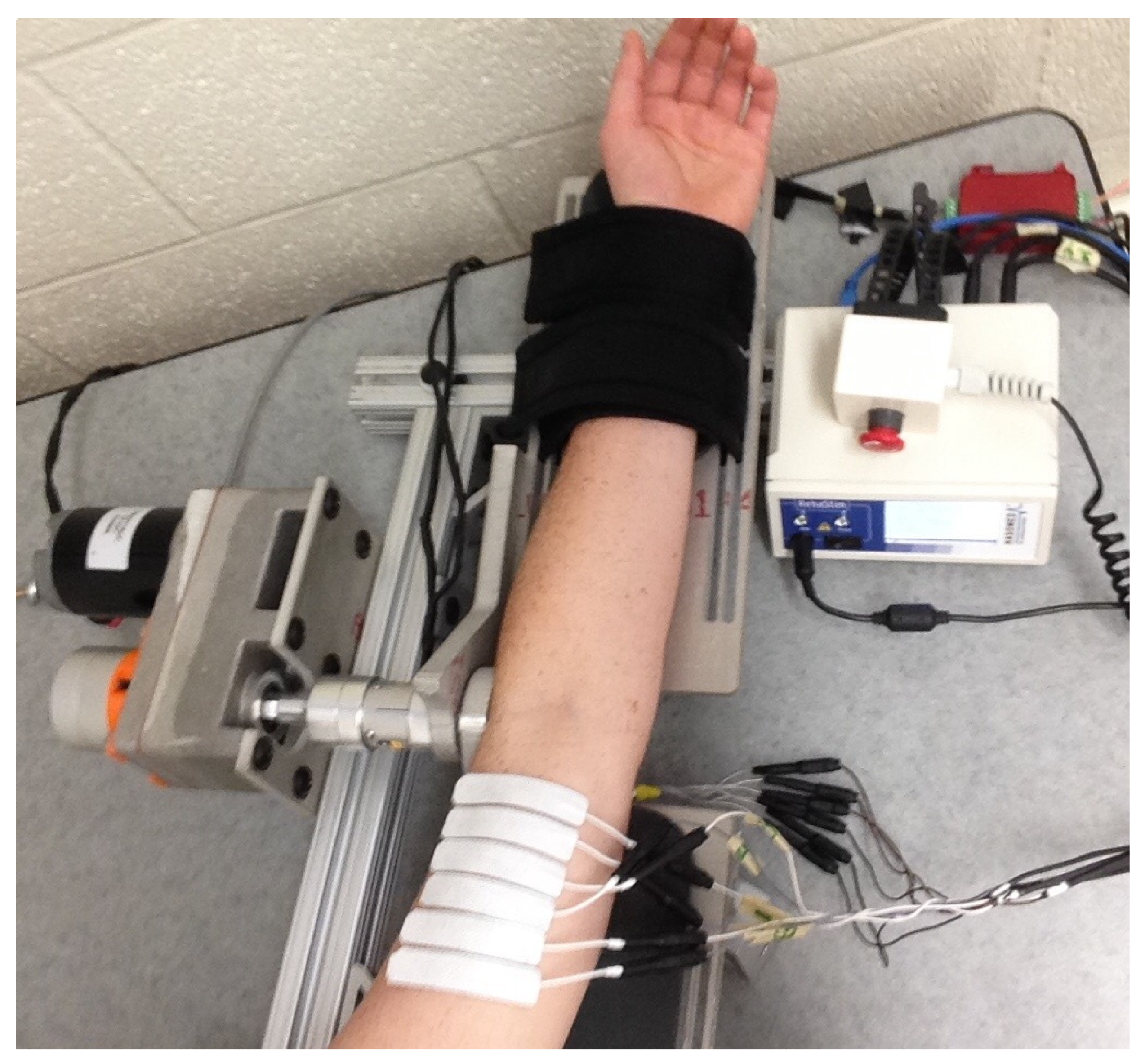
For the experiments, a customized testbed, seen in Figure 2, composed of two rectangular aluminum plates was used. The triceps side of the upper arm rested on a stationary plate and the forearm was fixed to the other plate with velcro straps and rotated about a hinge aligned with the elbow. The designed motor controller was applied to a 27 Watt, brushed, parallel-shaft 12 VDC electric gearmotor and the FES controller regulated the pulsewidth sent to six 0.6” × 2.75” Axelgaard electrodes on the biceps brachii via a Hasomed stimulator, as in [22]. The controllers were implemented using real-time control software (QUARC, MATLAB 2015b/Simulink, Windows 8). The placement of the electrodes, which can be seen in Figure 2, followed a strict procedure to ensure consistent biceps coverage and evenly spaced electrode placement. The first electrode was placed at 21% of the distance from the elbow crease to the acromion, the sixth electrode at 50% of this distance, and the other four biceps electrodes spaced evenly between the first and last. A seventh electrode (3” × 5”) was placed on the shoulder as the reference electrode for all six biceps electrode channels. Based on comfort and necessary torque values, stimulation amplitude was fixed at a current of 30 mA with a frequency of 35 Hz for each channel, while the closed-loop FES controller modulated the pulse-width.

2.5.2. Protocol

After all seven electrodes were placed on the subject’s upper arm, the subject was seated such that the upper arm and forearm could comfortably rest on their respective parts of the testbed. The desired angular position, q d , of the forearm was selected as q d t = 7 π 18 1 cos π 2 t 5 T + π 9 , t 5 4 t , t < 5 , where the period, T , or amount of time for the forearm to move from 20 to 90 degrees, was 5 s. The motor first brought the arm to 20 degrees, which was found to be the beginning of the region where the muscle could always produce sufficient torque, and, from there, 10 biceps curls were completed.
The control gains, k i i = 1 , . . , 4 , k i , β i = 5 , 8 , introduced in (12) and (13), were adjusted to yield acceptable tracking performance with values for both the right and left arms as follows: k 1 = 25 ,   k 2 = k 3 = k 4 = 1 ,   k 5 , 0 = 15 ,   k 5 , 1 = 35 ,   k 6 , β = k 7 , β = k 8 , β = 1 . A saturation limit for the muscle control input was established based on comfort, where the procedure for doing so involved slowly increasing the stimulation level (i.e., current) until the participant states they would like no higher stimulation. The decay constant for γ j was selected as ρ = 0.8 . When the muscle control input was below saturation, electrical stimulation was used to control the forearm from 20 to 90 degrees, whereas both muscle stimulation and the DC motor were used at any point that the muscle controller reached the saturation limit. Only the DC motor brought the forearm from the highest forearm angle (90 degrees) to the starting position (20 degrees). The set of channels used to stimulate within the muscle control region (i.e., during flexion) varies with angular position as in [19], where ε = 0.22 was selected as the normalized torque threshold for all but the impaired right arm of the Subject 1, which was set to 0.10 due to no electrode locations producing sufficient isometric torque.

3. Results

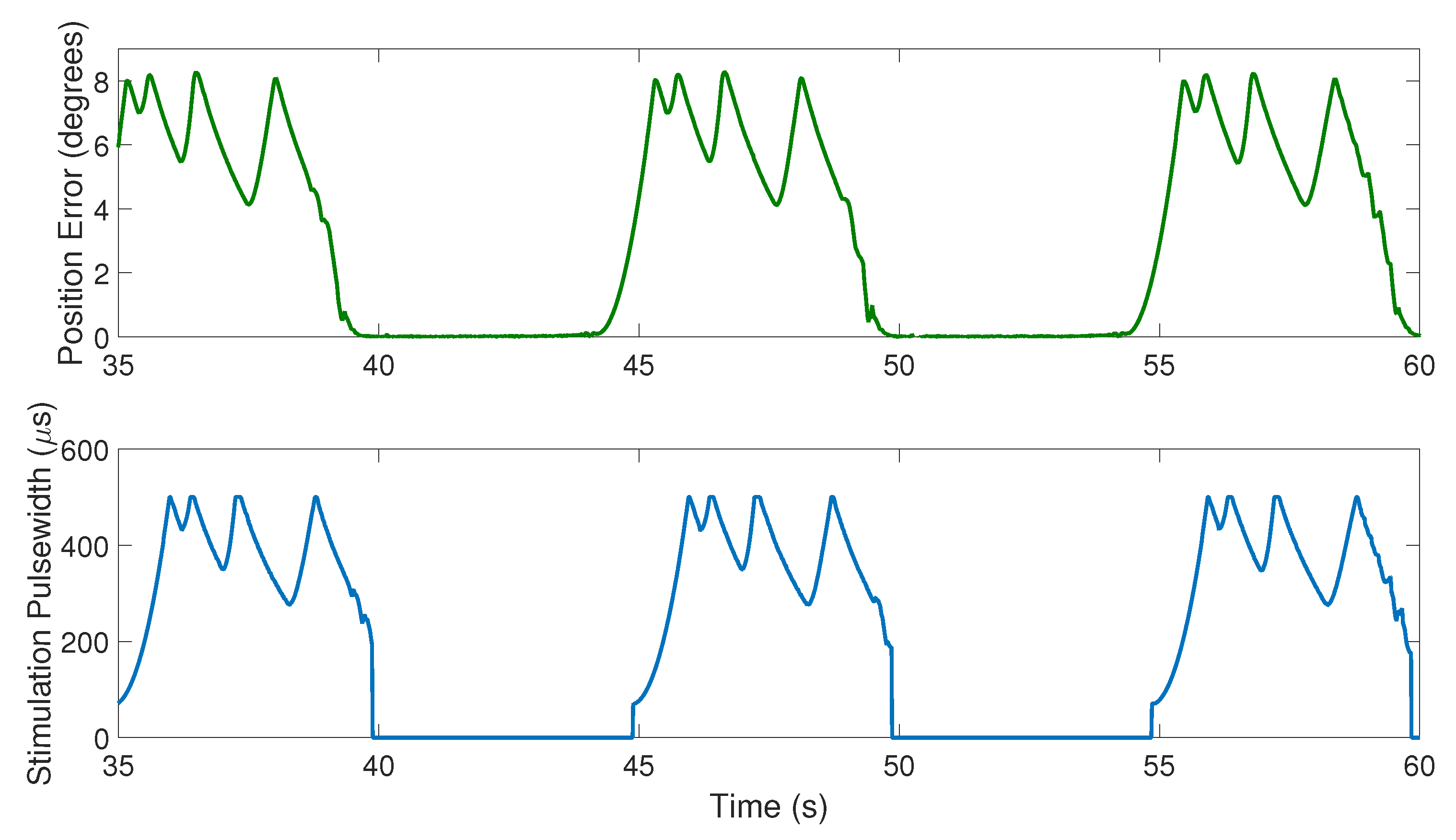
Average RMS position and velocity errors, along with average FES and motor control inputs for the impaired and unimpaired arms of each participant are compared in Table 1. All statistics are averaged over times of desired flexion. No data from when the arm was in extension was used. Figure 3 shows both the position error and FES control input (stimulation pulsewidth) for the right (impaired) arm of Participant 2 during biceps curls 4–6.

4. Discussion

The results in Table 1 show that the average position and velocity errors of the impaired arm are similar to that of the unimpaired arm for both participants, despite each having movement disorders that significantly limit performing daily activities with their impaired arm. By design, the motor only contributes as needed and the FES activates the biceps throughout flexion. The goal of rehabilitation is generally to challenge the patient to build muscle and coordination, but not so much that they can only perform a limited number of repetitions. The assist-as-needed motor controller, in combination with the FES-controller, allows for this sort of rehabilitation goal and are a promising development for rehabilitation robotics.
Since the control system essentially replaces the broken neurological pathways in the participant and, since volitional effort was not encouraged, it may be expected that the experiments on the participant’s impaired arms performed similar to their healthy arms; however, there are many factors that the control system must account for in a healthy vs. impaired limb. For instance, the impaired limb is likely not used much in daily activities, and, thus, has atrophied and requires more FES and motor assistance, for which the control system automatically adjusts. Moreover, the electrodes used in this study were surface electrodes placed on the skin, which may not penetrate deep enough to reach all muscle fibers, which may disproportionately affect the impaired arm that already takes more control input to move. Lastly, the first participant had physical damage in addition to neurological damage in his impaired right arm, which the designed control system was able to account for.
In [19], exponential tracking of the desired elbow angle trajectory is achieved and the motor assists when the stimulation comfort threshold Γ is reached; however, the motor only assists for an instant before the error drops, resulting in the FES control input to fall below the single threshold Γ . This method resulted in the motor being frequently activated and deactivated (i.e., chattering), in addition to the chattering that can result from sliding mode control. Not only does this fail to accurately mimic the relatively consistent and smooth muscle contractions achieved during voluntary exercise, it is also undesirable from a control and hardware perspective. Comparing the error and stimulation results in Figure 3 of this paper to Figures 3 and 4 of [19], it can be seen that both the stimulation and the error smoothly increase and decrease in the current experiments, but change very quickly around the threshold value in [19]. Since the motor control input is mathematically dependent on the FES control input, when the FES control input is chattering, so is the motor. Moreover, the reliance on the motor for longer bouts results in lower average position and velocity errors. The results from [19] motivated the control design in this paper, where the motor continues to assist the muscle until u m reaches the lower threshold γ j . Moreover, to prevent the motor from turning on and off more frequently as the biceps fatigues, the motor remains activated until the position and velocity errors are low enough to result in an FES control input of γ j . This does not guarantee that the motor is activated over a longer amount of time or range of elbow angles, which is typically the result because it takes more time for u m to rise back to Γ . However, if a physical therapist or other rehabilitation specialist desired, ρ = 1 would cause the lower threshold to remain constant throughout the protocol.
As seen in Figure 3, as an example of a typical portion of an experiment, changes in the stimulation pulsewidth mirror changes in the position error, but with a short lag time. This is not surprising given the design of the FES control input in (12); the lagged mirroring occurs because the FES control input is a function of the error and thus changes when the error changes. However, the relation is dependent on control gains. In this experiment, α = 40 was selected, meaning that the dependence of e 2 (and thus the FES control input) on the position error is 40 times greater than its dependence on the velocity error. Thus, the control input nearly mirrors the position error, which decreases during the bouts of continuous motor assistance. The control gain α was selected as such because any more dependence on the velocity error resulted in small but frequent changes in direction. This is because any undesired movement in the negative direction during flexion was amplified just as much as movement in the positive direction.
The control technique in this paper may depend on muscle delay even more so than other FES protocols [29]. Because the motor instantaneously switches off after the γ j condition is met, the muscle must react to the rapid increase in stimulation back to Γ that often occurred, as seen in Figure 3, which is likely a combination of fatigue, an insufficiently high comfort threshold, and/or muscle delay. Methods from recent studies on delay in FES cycling [30] could be applied to the FES protocol in this biceps curl study.

5. Conclusions

In this paper, an FES controller is used to track a desired elbow angle trajectory resembling a typical biceps curl on a customized arm testbed, and a motor controller is designed to assist when needed. It is critical for patient comfort to select an individualized threshold for the FES control input. Rather than allowing error growth and high stimulation, an electric motor temporarily assists with elbow flexion, resulting in a decrease in error and stimulation intensity. From a rehabilitation perspective, it is desired to work a patient’s muscles sufficiently to build muscle and strength, but not so much that the patient fatigues too quickly to achieve other rehabilitative benefits such as improving range of motion and cardiovascular exercise. The method developed in this paper, which includes switched sliding mode controllers for both the FES and motor control input, is a promising development for rehabilitation robots and resulted in four successful sets of experimental data on two participants with asymmetrical impairments. Future long-term studies are necessary to measure improvements in rehabilitative outcomes.

Author Contributions

C.R. contributed to the project outlined in this manuscript with data curation, formal analysis, investigation, methodology, project administration, resources, visualization, and writing—original draft. W.D. contributed with conceptualization, funding acquisition, supervision, validation, and writing—review and editing. B.A. contributed with validation and writing—review and editing. All authors have read and agreed to the published version of the manuscript.

Funding

This material is based upon work supported by the National Science Foundation Graduate Research Fellowship Program under Grant No. DGE-1315138, NSF Award number 1762829, and AFOSR award number FA9550-18-1-0109. Any opinions, findings and conclusions, or recommendations expressed in this material are those of the author(s) and do not necessarily reflect the views of the sponsoring agency.

Conflicts of Interest

The authors declare no conflict of interest.

Abbreviations

The following abbreviations are used in this manuscript:
MDPIMultidisciplinary Digital Publishing Institute
DOAJDirectory of Open Access Journals
FESFunctional Electrical Stimulation
DCDirect Current
VDCVoltage Direct Current

References

  1. Aisen, M.L.; Krebs, H.I.; Hogan, N.; McDowell, F.; Volpe, B.T. The effect of robot-assisted therapy and rehabilitative training on motor recovery following stroke. Arch. Neurol. 1997, 54, 443–446. [Google Scholar] [CrossRef]
  2. Masiero, S.; Celia, A.; Rosati, G.; Armani, M. Robotic-Assisted Rehabilitation of the Upper Limb After Acute Stroke. Arch. Phys. Med. Rehabil. 2007, 88, 142–149. [Google Scholar] [CrossRef]
  3. Riener, R.; Nef, T.; Colombo, G. Robot-aided neurorehabilitation of the upper Extremities. Med. Biol. Eng. Comput. 2005, 43, 2–10. [Google Scholar] [CrossRef] [Green Version]
  4. Zollo, L.; Gallotta, E.; Guglielmelli, E.; Sterzi, S. Robotic technologies and rehabilitation: New tools for upper-limb therapy and assessment in chronic stroke. Eur. J. Phys. Rehabil. Med. 2011, 47, 223–236. [Google Scholar]
  5. Poli, P.; Morone, G.; Rosati, G.; Masiero, S. Robotic Technologies and Rehabilitation: New Tools for Stroke Patients Therapy. Biomed. Res. Int. 2013, 2013, 153872. [Google Scholar] [CrossRef]
  6. Combs, S.; Kelly, S.; Barton, R.; Ivaska, M.; Nowak, K. Effects of an intensive, task-specific rehabilitation program for individuals with chronic stroke: A case series. Disabil. Rehabil. 2010, 32, 669–678. [Google Scholar] [CrossRef]
  7. Fritz, S.; Merlo-Rains, A.; Rivers, E.; Brandenburg, B.; Sweet, J.; Donley, J.; Mathews, H.; deBode, S.; McClenaghan, B. Feasibility of intensive mobility training to improve gait, balance, and mobility in persons with chronic neurological conditions: A case series. J. Neurol. Phys. Ther. 2011, 35, 141–147. [Google Scholar] [CrossRef]
  8. Kwakkel, G.; Veerbeek, J.; van Wegen, E.; Wolf, S. Constraint-Induced Movement Therapy after Stroke. Lancet Neurol. 2015, 14, 224–234. [Google Scholar] [CrossRef] [Green Version]
  9. Krebs, H.I.; Palazzolo, J.J.; Dipietro, L.; Ferraro, M.; Krol, J.; Rannekleiv, K.; Volpe, B.T.; Hogan, N. Rehabilitation robotics: Performance-based progressive robot-assisted therapy. Auton. Robot. 2003, 15, 7–20. [Google Scholar] [CrossRef]
  10. Cousin, C.; Duenas, V.H.; Rouse, C.; Dixon, W.E. Admittance Trajectory Tracking using a Challenge-Based Rehabilitation Robot with Functional Electrical Stimulation. In Proceedings of the 2018 Annual American Control Conference (ACC), Milwaukee, WI, USA, 27–29 June 2018; pp. 3732–3737. [Google Scholar]
  11. Frullo, J.; Elinger, J.; Pehlivan, A.U.; Fitle, K.; Nedley, K.; Sergi, F.; O’Malley, M.K. Effects of Assist-As-Needed Upper Extremity Robotic Therapy after Incomplete Spinal Cord Injury: A parallel-Group Controlled Trial. Front. Neurorobot. 2017, 11, 26. [Google Scholar] [CrossRef] [Green Version]
  12. Pehlivan, A.U.; Sergi, F.; O’Malley, M.K. A Subject-Adaptive Controller for Wrist Robotic Rehabilitation. IEEE Trans. Mechatron. 2015, 20, 1338–1350. [Google Scholar] [CrossRef]
  13. Chemuturi, R.; Amirabdollahian, F.; Dautenhahn, K. Adaptive training algorithm for robot-assisted upper-arm rehabilitation, applicable to individualised and therapeutic human–robot interaction. J. Neuroeng. Rehabil. 2013, 10, 102. [Google Scholar] [CrossRef] [Green Version]
  14. Pehlivan, A.U.; Losey, D.P.; O’Malley, M.K. Minimal assist-as-needed controller for upper limb robotic rehabilitation. IEEE Trans. Robot. 2016, 32, 113–124. [Google Scholar] [CrossRef]
  15. Gomis, M.; Gonzalez, L.; Querol, F.; Gallach, J.; Toca-Herrera, J. Effects of electrical stimulation on muscle trophism in patients with hemophilic arthropathy. Arch. Phys. Med. Rehabil. 2009, 90, 1924–1930. [Google Scholar] [CrossRef]
  16. Sonde, L.; Gip, C.; Fernaeus, S.; Nilsson, C.; Viitanen, M. Stimulation with low frequency (1.7 Hz) transcutaneous electric nerve stimulation (low-tens) increases motor function of the post-stroke paretic Arm. Scand. J. Rehabil. Med. 1998, 30, 95–99. [Google Scholar] [CrossRef]
  17. McCabe, J.; Monkiewicz, M.; Holcomb, J.; Pundik, S.; Daly, J.J. Comparison of robotics, functional electrical stimulation, and motor learning methods for treatment of persistent upper extremity dysfunction after stroke: A randomized controlled trial. Arch. Phys. Med. Rehabil. 2015, 96, 981–990. [Google Scholar] [CrossRef] [Green Version]
  18. Langhammer, B.; Stanghelle, J. Bobath or motor relearning program? A comparison of two different approaches of physiotherapy in stroke rehabilitation: A randomised controlled Study. Clin. Rehabil. 2000, 14, 361–369. [Google Scholar] [CrossRef] [Green Version]
  19. Rouse, C.; Cousin, C.; Duenas, V.H.; Dixon, W.E. Switched Motorized Assistance during Switched Functional Electrical Stimulation of the Biceps Brachii to Compensate for Fatigue. In Proceedings of the IEEE Conference on Decision and Control, Melbourne, Australia, 12–15 December 2017; pp. 5912–5918. [Google Scholar]
  20. Rouse, C.; Cousin, C.; Duenas, V.H.; Dixon, W.E. Varying Motor Assistance During Biceps Curls Induced Via Functional Electrical Stimulation. In Proceedings of the ASME Dynamic Systems and Control Conference, Atlanta, Georgia, 30 September–3 October 2018. [Google Scholar]
  21. Rouse, C.; Duenas, V.H.; Cousin, C.; Parikh, A.; Dixon, W.E. A Switched Systems Approach Based on Changing Muscle Geometry of the Biceps Brachii During Functional Electrical Stimulation. IEEE Control Syst. Lett. 2018, 2, 73–78. [Google Scholar] [CrossRef]
  22. Gonzalez, E.J.; Downey, R.J.; Rouse, C.A.; Dixon, W.E. Influence of Elbow Flexion and Stimulation Site on Neuromuscular Electrical Stimulation of the Biceps Brachii. IEEE Trans. Neural Syst. Rehabil. Eng. 2018, 26, 904–910. [Google Scholar] [CrossRef]
  23. Sharma, N.; Stegath, K.; Gregory, C.M.; Dixon, W.E. Nonlinear Neuromuscular Electrical Stimulation Tracking Control of a Human Limb. IEEE Trans. Neural Syst. Rehabil. Eng. 2009, 17, 576–584. [Google Scholar] [CrossRef] [Green Version]
  24. Schauer, T.; Negård, N.O.; Previdi, F.; Hunt, K.J.; Fraser, M.H.; Ferchland, E.; Raisch, J. Online identification and nonlinear control of the electrically stimulated quadriceps muscle. Control Eng. Pract. 2005, 13, 1207–1219. [Google Scholar] [CrossRef] [Green Version]
  25. Ferrarin, M.; Pedotti, A. The Relationship Between Electrical Stimulus and Joint Torque: A Dynamic Model. IEEE Trans. Rehabil. Eng. 2000, 8, 342–352. [Google Scholar] [CrossRef]
  26. Fischer, N.; Kamalapurkar, R.; Dixon, W.E. LaSalle-Yoshizawa Corollaries for Nonsmooth Systems. IEEE Trans. Autom. Control 2013, 58, 2333–2338. [Google Scholar] [CrossRef] [Green Version]
  27. Paden, B.E.; Sastry, S.S. A calculus for computing Filippov’s differential inclusion with application to the variable structure control of robot manipulators. IEEE Trans. Circ. Syst. 1987, 34, 73–82. [Google Scholar] [CrossRef]
  28. Liberzon, D. Switching in Systems and Control; Birkhauser: Basel; Switzerland, 2003. [Google Scholar]
  29. Downey, R.; Merad, M.; Gonzalez, E.; Dixon, W.E. The Time-Varying Nature of Electromechanical Delay and Muscle Control Effectiveness in Response to Stimulation-Induced Fatigue. IEEE Trans. Neural Syst. Rehabil. Eng. 2017, 25, 1397–1408. [Google Scholar] [CrossRef]
  30. Allen, B.; Cousin, C.; Rouse, C.; Dixon, W.E. Cadence Tracking For Switched FES-Cycling with Unknown Time-Varying Input Delay. In Proceedings of the ASME Dynamic Systems and Control (DSC) Conference, Park City, UT, USA, 8–11 October 2019. [Google Scholar]
Figure 1. For a given calculated control input and set of FES thresholds, the diagram shows whether FES, motor, or both will control the forearm rotation.
Applsci 10 08090 g001
Figure 2. Six electrodes connected to a stimulator are evenly spaced on a particpants biceps brachii. The participant’s elbow joint is aligned with the motorized testbed’s joint axis. An emergency stop button is provided for participants to voluntarily stop the test at any time.
Applsci 10 08090 g002
Figure 3. Position error and stimulation pulsewidth (i.e., FES input) for the right arm of Participant 2 during trials where the lower stimulation threshold iteratively decreased according to the constant ρ = 0.8 . The zoomed view of biceps curls 4–6 is provided to easily compare the change in FES control input to the position error.
Applsci 10 08090 g003
Table 1. Average position and velocity errors, FES control input, and motor control input for both arms (one impaired, one unimpaired) for both subjects. S1 and S2 denote Subjects 1 and 2; R and L denote the right and left arms.
RMS Position Error (deg)RMS Velocity Error (deg/s)Average FES Control Input ( μ s)Average Motor Control Input (Amps)
S1, Impaired/R Arm 4.26 3.70 286.7 2.08
S1, Unimpaired/L Arm 3.75 4.33 317.6 1.61
S2, Impaired/R Arm 4.83 5.56 354.0 1.79
S2, Unimpaired/L Arm 4.96 5.04 346.0 1.67
Publisher’s Note: MDPI stays neutral with regard to jurisdictional claims in published maps and institutional affiliations.