Abstract
We demonstrate the beneficial effects of introducing glide symmetry in a two-dimensional periodic structure. Specifically, we investigate dielectric parallel plate waveguides periodically loaded with Jerusalem cross slots in three configurations: conventional, mirror- and glide-symmetric. Out of these three configurations, it is demonstrated that the glide-symmetric structure is the least dispersive and has the most isotropic response. Furthermore, the glide-symmetric structure provides the highest effective refractive index, which enables the realization of a broader range of electromagnetic devices. To illustrate the potential of this glide-symmetric unit cell, a Maxwell fish-eye lens is designed to operate at 5 GHz. The lens is manufactured in printed circuit board technology. Simulations and measurements are in good agreement and a measured peak transmission coefficient of −0.5 dB is achieved.
1. Introduction
A periodic structure is said to possess a higher symmetry if it has an additional geometrical symmetry beyond its translational symmetry. One particular type of higher symmetry is glide symmetry. A glide-symmetric structure is invariant under a translation by half a period and a reflection in a glide plane [1]. Higher symmetries in one dimensional periodic structures were extensively studied for electromagnetic purposes in the 1960s and 1970s [1,2,3,4,5] (some earlier works on helical twist-symmetric structures exist [6,7]). These works outlined a theoretical basis for the analysis of higher-symmetric structures but did not highlight all details of the propagation characteristics in these structures. Recently, it was demonstrated that higher-symmetric periodic structures provide attractive properties; for instance, the possibility of realizing a higher value of the effective refractive index [8,9,10,11] and a reduction of the intrinsic frequency dispersion in periodic structures [12,13,14,15,16,17]. It was also discovered that glide-symmetric metasurfaces can support edge modes [18], provide an increased control of the anisotropy [19] and effective permeability [20] in two-dimensional (2D) periodic structures. In other words, the recent studies demonstrate that higher symmetries provide an additional degree of freedom to control the wave propagation in periodic structures [11,14,19,21,22,23,24,25], which enables the design of novel millimeter wave devices; such as lenses [26,27,28], filters [29,30], phase shifters [31,32,33], polarizers [34,35,36,37] and low-cost efficient high-frequency waveguides and antennas [38,39,40,41]. Additionally, glide-symmetric holey structures have been used to suppress the leakage between waveguide flanges, which enables contact-less measurements of electromagnetic devices [42]. The attractive properties found in higher-symmetric structures have inspired several works on numerical methods for the analysis [16,43,44,45,46,47,48,49,50]. These methods also give valuable physical insight.
Due to the forthcoming increase of the operation frequency to millimeter waves in communication systems [51], the requirements on transmitters and receivers are increasing. For instance, highly directive antennas are required to compensate for the increase in the free space path loss [52]. Graded index lenses are a viable option to achieve highly directive antennas at millimeter wave frequencies [52,53,54,55,56,57,58,59]. One example of a graded index lens is the Maxwell fish-eye (MFE) lens. The MFE lens is a rotationally symmetric lens that converges electromagnetic waves passing through a point in space to its antipodal point [60], and it is an attractive solution for imaging systems. Due to the rotational symmetry, the focusing property of the MFE lens is maintained for all angles and there is an ongoing debate among scientists whether or not the MFE lens has the ability of perfect imaging [61,62,63,64,65,66,67,68,69,70,71]. Furthermore, the half MFE (HMFE) lens has received significant attention [53,54,55,56,57,58] due to its ability to transform a spherical wave into a planar wave, similar to a Luneburg lens [26,59,72]. Contrary to the Luneburg lens, reflection occurs at output of the HMFE lens. Additionally, since the rotational symmetry is broken in the HMFE lens, the scanning capabilities are limited. However, the HMFE lens is half the size of the Luneburg lens and is thus useful for size-constrained applications where only a limited scanning is required.
In this work, we study the effect of introducing glide symmetry into a 2D periodic structure. Specifically, we analyze a parallel plate waveguiding structure where one or both of the conductors are loaded with slots. It is demonstrated that a less dispersive and higher effective refractive index is obtained in a glide-symmetric structure, compared to its non-glide-symmetric counterparts. The large achievable range of effective refractive indices enables a variety of microwave devices to be realized. Here, we design a planar MFE lens in printed circuit board (PCB) technology using the analyzed glide-symmetric structure. In fact, without glide symmetry, the performance of the designed lens is severely limited. A prototype of the lens is constructed in order to corroborate the simulations.
2. Glide Symmetry
A periodic structure is glide-symmetric if it is invariant under a translation and a reflection. A 2D glide-symmetric structure implemented in a parallel plate waveguide (PPW) is exemplified in Figure 1. The inset displays a top view of the unit cell. The displacement between the discontinuities in the top and bottom plates is , where p is the periodicity.
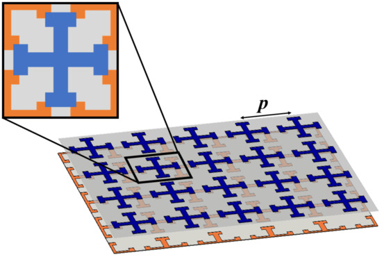
Figure 1.
Illustration of a 2D glide-symmetric structure implemented in a PPW. The orange and blue crosses are placed on the bottom and top conductor, respectively. The inset displays a top view of the unit cell.
The effect of the displacement between the discontinuities on the propagation characteristics in a 2D periodic structure is illustrated in Figure 2, where the dispersion diagram is obtained using the eigenmode solver of CST Microwave Studio [73]. The analyzed structure is a PPW with Jerusalem cross slots placed in both conductors, as illustrated in Figure 2a. The displacement of the slots, s, is varied from perfectly aligned () to glide-symmetric (). For a shift smaller than , there is a stop band between the first and second modes and the modes experience significant dispersion near this stop band. However, for , the stop band is suppressed and the modes connect. Therefore, the group velocity is no longer required to be zero at the band edge and the dispersion is reduced. Furthermore, it is observed that the refractive index in the glide-symmetric configuration is increased, compared to the non-glide-symmetric structures. In the following sections, these properties of glide-symmetric structures are employed to design a planar Maxwell fish-eye lens.
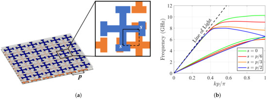
Figure 2.
Illustration of the effect of displacing the cross in the two PPW layers: (a) periodic structure with a top view of the unit cell as an inset, and (b) simulated dispersion diagram for different displacements.
3. Lens Design
3.1. Unit Cell Design
The studied unit cells are composed of two metallic layers with a dielectric in between, illustrated in Figure 3a. A Jerusalem cross slot is placed in the top metallic layer, as illustrated in Figure 3b. The three studied structures have different bottom conductors. Two reference structures are analyzed, with a solid bottom conductor (Figure 3c) and with a mirror-symmetric Jerusalem cross slot in the bottom conductor (Figure 3d). The third structure has a glide-symmetric Jerusalem cross slot in the bottom conductor (Figure 3e). The metallic layers have a thickness of mm.
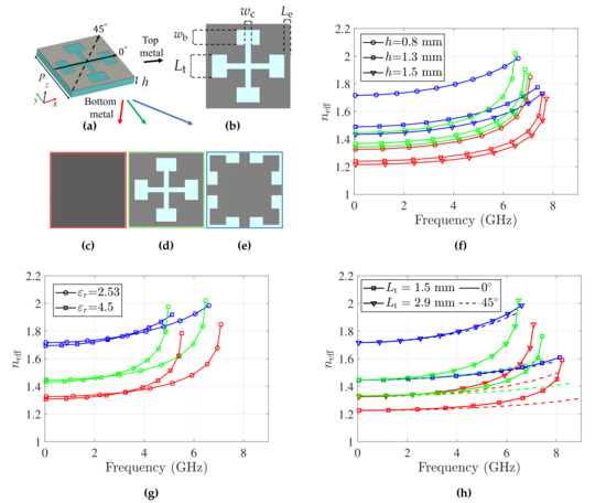
Figure 3.
Dispersion analysis for the dielectric parallel plate waveguide loaded with Jerusalem cross slots. The unit cell is illustrated in (a) perspective view, and (b) top view. Three unit cell configurations with different bottom metallic conductors are studied: (c) conventional, (d) mirror-, and (e) glide-symmetric. Effective refractive index for different values of: (f) the substrate thickness, h, (g) the substrate permittivity, εr, and (h) the parameter Lt. The level of isotropy is illustrated in (h). The red, green and blue curves correspond to the conventional, mirror- and glide-symmetric unit cells. The parameters are (unless otherwise specified)
mm, mm, mm, mm, mm, mm, and . A normalization factor of is applied to .
The three unit cells are modeled and simulated with the Eigenmode solver of CST. The normalized effective refractive index (with ) for a parametric sweep of the different structures is presented in Figure 3f–h. The parameters are (unless otherwise specified) mm, mm, mm, mm, mm, mm, and . From the parametric sweep, we observe that the glide-symmetric structure has the least dispersive response and provides a higher effective refractive index. Furthermore, in Figure 3h, the effective refractive index for waves propagating in two directions ( and with respect to the x-axis) is presented. The response of the glide-symmetric structure is almost isotropic, which is not the case over a wider range of frequencies compared to the reference structures. A less dispersive behavior entails a broader bandwidth for the device. A relative measure of the dispersion can be obtained by comparing the change of the effective refractive index around a reference value at a given frequency. For instance, if we allow a maximum change of 2% around the normalized effective refractive index value 2 at 5 GHz the bandwidth is 4.7%, 5.2% and 19% for the conventional, mirror- and glide-symmetric structures. Hence, the 2%-deviation bandwidth around an effective refractive index of 2 is almost four times larger in the glide-symmetric structure, compared to its non-glide counterparts. The acceptable deviation from the nominal value, and the bandwidth increase, depends on the intended application.
3.2. Maxwell Fish-Eye Lens
The refractive index profile of an MFE lens is given by
where is the refractive index of the surrounding media, a is the radius of the lens and r is the radial position in the lens. The refractive index must range from to . Such variation can be achieved with the glide-symmetric structure by varying the parameters and , as illustrated in Figure 4. The refractive index profile (1) is realized by spatially varying and throughout the lens. A rendition of the lens is presented in Figure 5a. The radius of the lens, a, is 130 mm. The prototype of the lens is displayed in Figure 5b and it is manufactured on a mm thick Teflon substrate ( and ).
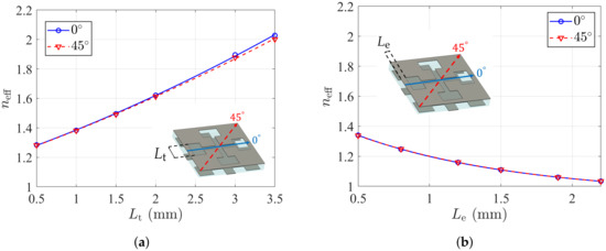
Figure 4.
Effective refractive index at 5 GHz for a parametric sweep of: (a) Lt and (b) Le. The blue and red line represent a wave traveling in the 0° and 45° directions, with respect to the x-axis. The effective refractive index is normalized with . The parameters are mm (Figure 4a), mm (Figure 4b), mm, mm (Figure 4a), mm (Figure 4b), mm, mm, and .
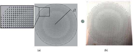
Figure 5.
Top view of the designed lens: (a) rendition, and (b) manufactured prototype.
Metallic vias are placed along the perimeter of the lens to emulate a cylindrical metallic wall. In this way, the feed and image point can be moved inside the lens [74]. This is done to avoid uncontrolled reflection at the termination of the PPW, which facilitates the characterization of the lens. The vias have a diameter of mm, are placed at the radius a, and are separated by mm (center to center).
3.3. Feed Design
Due to the metallic shielding of the lens, an omnidirectional feed can be used. Therefore, the lens is fed by a probe placed at the radius mm. A probe is also placed at the corresponding image point. In order to match the impedance of the lens to the generator impedance (50 Ω), a single-stub matching circuit is designed in microstrip technology. The matching circuit is illustrated in Figure 6a. The simulated reflection coefficient for the matching circuit when loaded with a 0.8 mm high PPW is presented in Figure 6b. The manufactured matching circuit is presented in the inset of Figure 6b. The dimensions are mm, mm, mm, mm, mm and mm and the circuit is manufactured on a mm thick Teflon substrate ( and ).
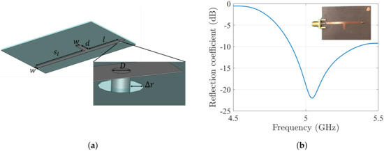
Figure 6.
Simulation results of the matching circuit: (a) 3D model and (b) reflection coefficient when loaded with a dielectric PPW. The manufactured prototype is presented in the inset. The dimensions are mm, mm, mm, mm, mm and mm. The circuit is manufactured on a 0.8 mm thick Teflon substrate ( and ).
4. Results
The full lens is simulated in the Time domain solver of CST. Waveguide ports are used to excite a quasi-TEM mode on the matching circuits which in turn are connected to the lens with vias. The imaging properties of the lens are illustrated in Figure 7a with the absolute value of the electric field sampled at GHz. The lens is excited at probe 1, which is connected to the matching circuit through a hole in the bottom conductor of the PPW. An image is created at the antipodal point, where probe 2 is placed, similarly connected to a matching circuit.
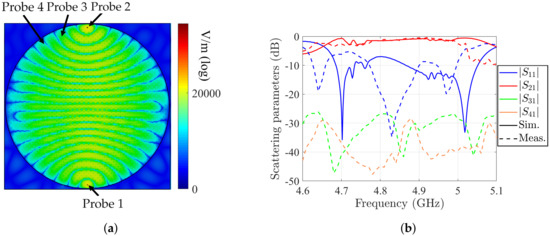
Figure 7.
(a) Absolute value of the electric field distribution at 4.8 GHz obtained with CST simulation. (b) Simulated (solid lines) and measured (dashed lines) scattering parameters.
The simulated and measured scattering parameters are presented in Figure 7b. The simulation and measurement agrees well, apart from a slight frequency shift. However, since the distance between peaks in the is similar in the simulations and measurements, the reflections occur at the same location in the structure. The frequency shift is accounted for by the error margin in the relative permittivity of the substrate. The measured has a peak value of −0.5 dB and it is above −3 dB from 4.63 to 5.03 GHz. The bandwidth depends on the refractive index variation and the feed design. Two more probes are connected to the lens at the same radius as the feed probe, but displaced and from the image point. The measured transmission coefficients to these probes are also included in Figure 7b and are below −25 dB.
5. Conclusions
In this paper, we have studied the effect of applying glide symmetry to a 2D periodic structure. We have demonstrated that a glide-symmetric structure presents a more isotropic and a less dispersive response compared to conventional periodic structures. Furthermore, a glide-symmetric structure can obtain a higher effective refractive index, which enables a wider range of devices to be realized. These properties have been used to design a PPW MFE lens in PCB technology operating at 5 GHz.
Without applying glide symmetry, the highest refractive index of the MFE lens could not be practically reached for this specific thickness of the slab and dielectric constant. Measurements of the lens agree well with the simulations, and the measured peak transmission coefficient through the lens is −0.5 dB.
Author Contributions
Conceptualization, O.Q.-T.; formal analysis, P.A. and O.B.P.; visualization, P.A. and O.B.P.; writing, original draft preparation, P.A. and O.B.P.; writing, review and editing, O.Z., F.G. and O.Q.-T.; supervision, O.Z., F.G. and O.Q.-T. All authors have read and agreed to the published version of the manuscript.
Funding
This research was partly funded by the Stiftelsen Åforsk project H-Materials (18-302).
Conflicts of Interest
The authors declare no conflict of interest
References
- Hessel, A.; Chen, M.H.; Li, R.; Oliner, A. Propagation in periodically loaded waveguides with higher symmetries. Proc. IEEE 1973, 61, 183–195. [Google Scholar] [CrossRef]
- Crepeau, P.; Mcisaac, P. Consequences of symmetry in periodic structures. Proc. IEEE 1964, 52, 33–43. [Google Scholar] [CrossRef]
- Trigg, G.L. Higher Symmetries. Phys. Rev. Lett. 1965, 14, 479. [Google Scholar]
- Mittra, R.; Laxpati, S. Propagation in a wave guide with glide reflection symmetry. Can. J. Phys. 1965, 43, 353–372. [Google Scholar] [CrossRef]
- Kieburtz, R.; Impagliazzo, J. Multimode propagation on radiating traveling-wave structures with glide-symmetric excitation. IEEE Trans. Antennas Propag. 1970, 18, 3–7. [Google Scholar] [CrossRef]
- Pocklington, H.C. Electrical oscillations in wires. Proc. Camb. Philos. Soc. 1897, 9, 324–332. [Google Scholar]
- Sensiper, S. Electromagnetic Wave Propagation on Helical Structures (A Review and Survey of Recent Progress). Proc. IRE 1955, 43, 149–161. [Google Scholar] [CrossRef]
- Chang, T.; Kim, J.U.; Kang, S.K.; Kim, H.; Kim, D.K.; Lee, Y.H.; Shin, J. Broadband giant-refractive-index material based on mesoscopic space-filling curves. Nat. Commun. 2016, 7. [Google Scholar] [CrossRef] [PubMed]
- Cavallo, D.; Felita, C. Analytical Formulas for Artificial Dielectrics With Nonaligned Layers. IEEE Trans. Antennas Propag. 2017, 65, 5303–5311. [Google Scholar] [CrossRef]
- Cavallo, D. Dissipation Losses in Artificial Dielectric Layers. IEEE Trans. Antennas Propag. 2018, 66, 7460–7465. [Google Scholar] [CrossRef]
- Dahlberg, O.; Ghasemifard, F.; Valerio, G.; Quevedo-Teruel, O. Propagation characteristics of periodic structures possessing twist and polar glide symmetries. EPJ Appl. Metamater. 2019, 6, 14. [Google Scholar] [CrossRef]
- Mitchell-Thomas, R.C.; Sambles, J.R.; Hibbins, A.P. High index metasurfaces for graded lenses using glide symmetry. In Proceedings of the 2017 11th European Conference on Antennas and Propagation (EUCAP), Paris, France, 19–24 March 2017; pp. 1396–1397. [Google Scholar]
- Camacho, M.; Mitchell-Thomas, R.C.; Hibbins, A.P.; Sambles, J.R.; Quevedo-Teruel, O. Designer surface plasmon dispersion on a one-dimensional periodic slot metasurface with glide symmetry. Opt. Lett. 2017, 42, 3375–3378. [Google Scholar] [CrossRef] [PubMed]
- Camacho, M.; Mitchell-Thomas, R.C.; Hibbins, A.P.; Sambles, J.R.; Quevedo-Teruel, O. Mimicking glide symmetry dispersion with coupled slot metasurfaces. Appl. Phys. Lett. 2017, 111, 121603. [Google Scholar] [CrossRef]
- Dahlberg, O.; Mitchell-Thomas, R.; Quevedo-Teruel, O. Reducing the dispersion of periodic structures with twist and polar glide symmetries. Sci. Rep. 2017, 7, 10136. [Google Scholar] [CrossRef] [PubMed]
- Ghasemifard, F.; Norgren, M.; Quevedo-Teruel, O. Dispersion Analysis of 2-D Glide-Symmetric Corrugated Metasurfaces Using Mode-Matching Technique. IEEE Microw. Wirel. Components Lett. 2018, 28, 1–3. [Google Scholar] [CrossRef]
- Ghasemifard, F. Periodic Structures with Higher Symmetries: Analysis and Applications. Ph.D. Thesis, Electrical Engineering School of Electrical Engineering and Computer Science, KTH Royal Institute of Technology, Stockholm, Sweden, 2018. [Google Scholar]
- De Pineda, J.D.; Hibbins, A.P.; Sambles, J.R. Microwave edge modes on a metasurface with glide symmetry. Phys. Rev. B 2018, 98, 205426. [Google Scholar] [CrossRef]
- Ebrahimpouri, M.; Quevedo-Teruel, O. Ultrawideband Anisotropic Glide-Symmetric Metasurfaces. IEEE Antennas Wirel. Propag. Lett. 2019, 18, 1547–1551. [Google Scholar] [CrossRef]
- Ebrahimpouri, M.; Herran, L.F.; Quevedo-Teruel, O. Wide-Angle Impedance Matching Using Glide-Symmetric Metasurfaces. IEEE Microw. Wirel. Components Lett. 2020, 30, 8–11. [Google Scholar] [CrossRef]
- Quesada, R.; Martín-Cano, D.; García-Vidal, F.J.; Bravo-Abad, J. Deep-subwavelength negative-index waveguiding enabled by coupled conformal surface plasmons. Opt. Lett. 2014, 39, 2990–2993. [Google Scholar] [CrossRef]
- Padilla, P.; Herrán, L.F.; Tamayo-Domínguez, A.; Valenzuela-Valdés, J.F.; Quevedo-Teruel, O. Glide Symmetry to Prevent the Lowest Stopband of Printed Corrugated Transmission Lines. IEEE Microw. Wirel. Compon. Lett. 2018, 28, 750–752. [Google Scholar] [CrossRef]
- Ghasemifard, F.; Norgren, M.; Quevedo-Teruel, O. Twist and Polar Glide Symmetries: An Additional Degree of Freedom to Control the Propagation Characteristics of Periodic Structures. Sci. Rep. 2018, 8, 11266. [Google Scholar] [CrossRef] [PubMed]
- Tamayo-Dominguez, A.; Fernandez-Gonzalez, J.M.; Quevedo-Teruel, O. One-Plane Glide-Symmetric Holey Structures for Stop-Band and Refraction Index Reconfiguration. Symmetry 2019, 11, 495. [Google Scholar] [CrossRef]
- Padilla, P.; Palomares-Caballero, Á.; Alex-Amor, A.; Valenzuela-valdés, J.; Fernández-González, J.M.; Quevedo-Teruel, O. Broken Glide-Symmetric Holey Structures for Bandgap Selection in Gap-Waveguide Technology. IEEE Microw. Wirel. Components Lett. 2019, 29, 327–329. [Google Scholar] [CrossRef]
- Quevedo-Teruel, O.; Ebrahimpouri, M.; Ng Mou Kehn, M. Ultrawideband Metasurface Lenses Based on Off-Shifted Opposite Layers. IEEE Antennas Wirel. Propag. Lett. 2016, 15, 484–487. [Google Scholar] [CrossRef]
- Dahlberg, O.; Valerio, G.; Quevedo-Teruel, O. Fully Metallic Flat Lens Based on Locally Twist-Symmetric Array of Complementary Split-Ring Resonators. Symmetry 2019, 11, 581. [Google Scholar] [CrossRef]
- Shanei, M.M.; Fathi, D.; Ghasemifard, F.; Quevedo-Teruel, O. All-silicon reconfigurable metasurfaces for multifunction and tunable performance at optical frequencies based on glide symmetry. Sci. Rep. 2019, 9, 13641. [Google Scholar] [CrossRef]
- Monje-Real, A.; Fonseca, N.J.G.; Zetterstrom, O.; Pucci, E.; Quevedo-Teruel, O. Holey Glide-Symmetric Filters for 5G at Millimeter-Wave Frequencies. IEEE Microw. Wirel. Components Lett. 2020, 30, 31–34. [Google Scholar] [CrossRef]
- Mouris, B.A.; Fernandez-Prieto, A.; Thobaben, R.; Martel, J.; Mesa, F.; Quevedo-Teruel, O. Increment of the Bandwidth of Mushroom-type EBG Structures with Glide Symmetry. IEEE Trans. Microw. Theory Tech. 2020, 68, 1365–1375. [Google Scholar] [CrossRef]
- Rajo-Iglesias, E.; Ebrahimpouri, M.; Quevedo-Teruel, O. Wideband Phase Shifter in Groove Gap Waveguide Technology Implemented With Glide-Symmetric Holey EBG. IEEE Microw. Wirel. Components Lett. 2018, 28, 476–478. [Google Scholar] [CrossRef]
- Quevedo-Teruel, O.; Dahlberg, O.; Valerio, G. Propagation in Waveguides With Transversal Twist-Symmetric Holey Metallic Plates. IEEE Microw. Wirel. Components Lett. 2018, 28, 858–860. [Google Scholar] [CrossRef]
- Palomares-Caballero, A.; Alex-Amor, A.; Padilla, P.; Luna, F.; Valenzuela-Valdes, J. Compact and Low-Loss V-Band Waveguide Phase Shifter Based on Glide-Symmetric Pin Configuration. IEEE Access 2019, 7, 31297–31304. [Google Scholar] [CrossRef]
- Wei, Z.; Cao, Y.; Fan, Y.; Yu, X.; Li, H. Broadband polarization transformation via enhanced asymmetric transmission through arrays of twisted complementary split-ring resonators. Appl. Phys. Lett. 2011, 99, 221907. [Google Scholar] [CrossRef]
- Zhao, Y.; Belkin, M.; Alù, A. Twisted optical metamaterials for planarized ultrathin broadband circular polarizers. Nat. Commun. 2012, 3, 870. [Google Scholar] [CrossRef] [PubMed]
- Askarpour, A.; Zhao, Y.; Alu, A. Wave propagation in twisted metamaterials. Phys. Rev. Condens. Matter Mater. Phys. 2014, 90, 054305. [Google Scholar] [CrossRef]
- Zhao, Y.; Askarpour, A.N.; Sun, L.; Shi, J.; Li, X.; Alù, A. Chirality detection of enantiomers using twisted optical metamaterials. Nat. Commun. 2017, 8, 14180. [Google Scholar] [CrossRef] [PubMed]
- Ebrahimpouri, M.; Rajo-Iglesias, E.; Sipus, Z.; Quevedo-Teruel, O. Cost-Effective Gap Waveguide Technology Based on Glide-Symmetric Holey EBG Structures. IEEE Trans. Microw. Theory Tech. 2018, 66, 927–934. [Google Scholar] [CrossRef]
- Ebrahimpouri, M.; Quevedo-Teruel, O.; Rajo-Iglesias, E. Design Guidelines for Gap Waveguide Technology Based on Glide-Symmetric Holey Structures. IEEE Microw. Wirel. Components Lett. 2017, 27, 542–544. [Google Scholar] [CrossRef]
- Zetterstrom, O.; Pucci, E.; Padilla, P.; Wang, L.; Quevedo-Teruel, O. Low-Dispersive Leaky Wave Antennas for mmWave Point-to-Point High-Throughput Communications. IEEE Trans. Antennas Propag. 2020, 68, 1322–1331. [Google Scholar] [CrossRef]
- Chen, Q.; Zetterstrom, O.; Pucci, E.; Palomares-Caballero, A.; Padilla, P.; Quevedo-Teruel, O. Glide-Symmetric Holey Leaky-Wave Antenna with Low Dispersion for 60-GHz Point-to-Point Communications. IEEE Trans. Antennas Propag. 2019, 68, 1925–1936. [Google Scholar] [CrossRef]
- Ebrahimpouri, M.; Algaba Brazalez, A.; Manholm, L.; Quevedo-Teruel, O. Using Glide-Symmetric Holes to Reduce Leakage Between Waveguide Flanges. IEEE Microw. Wirel. Components Lett. 2018, 28, 473–475. [Google Scholar] [CrossRef]
- Valerio, G.; Sipus, Z.; Grbic, A.; Quevedo-Teruel, O. Accurate Equivalent-Circuit Descriptions of Thin Glide-Symmetric Corrugated Metasurfaces. IEEE Trans. Antennas Propag. 2017, 65, 2695–2700. [Google Scholar] [CrossRef]
- Valerio, G.; Ghasemifard, F.; Sipus, Z.; Quevedo-Teruel, O. Glide-Symmetric All-Metal Holey Metasurfaces for Low-Dispersive Artificial Materials: Modeling and Properties. IEEE Trans. Microw. Theory Tech. 2018, 66, 3210–3223. [Google Scholar] [CrossRef]
- Chen, Q.; Ghasemifard, F.; Valerio, G.; Quevedo-Teruel, O. Modeling and Dispersion Analysis of Coaxial Lines With Higher Symmetries. IEEE Trans. Microw. Theory Tech. 2018, 66, 4338–4345. [Google Scholar] [CrossRef]
- Ghasemifard, F.; Norgren, M.; Quevedo-Teruel, O.; Valerio, G. Analyzing Glide-Symmetric Holey Metasurfaces Using a Generalized Floquet Theorem. IEEE Access 2018, 6, 71743–71750. [Google Scholar] [CrossRef]
- Bagheriasl, M.; Valerio, G. Bloch Analysis of Electromagnetic Waves in Twist-Symmetric Lines. Symmetry 2019, 11, 620. [Google Scholar] [CrossRef]
- Bagheriasl, M.; Quevedo-Teruel, O.; Valerio, G. Bloch Analysis of Artificial Lines and Surfaces Exhibiting Glide Symmetry. IEEE Trans. Microw. Theory Tech. 2019, 67, 2618–2628. [Google Scholar] [CrossRef]
- Sipus, Z.; Bosiljevac, M. Modeling of Glide-Symmetric Dielectric Structures. Symmetry 2019, 11, 805. [Google Scholar] [CrossRef]
- Mesa, F.; Rodríguez-Berral, R.; Medina, F. On the Computation of the Dispersion Diagram of Symmetric One-Dimensionally Periodic Structures. Symmetry 2018, 10, 307. [Google Scholar] [CrossRef]
- Wang, Y.; Li, J.; Huang, L.; Jing, Y.; Georgakopoulos, A.; Demestichas, P. 5G Mobile: Spectrum Broadening to Higher-Frequency Bands to Support High Data Rates. IEEE Veh. Technol. Mag. 2014, 9, 39–46. [Google Scholar] [CrossRef]
- Quevedo-Teruel, O.; Ebrahimpouri, M.; Ghasemifard, F. Lens Antennas for 5G Communications Systems. IEEE Commun. Mag. 2018, 56, 36–41. [Google Scholar] [CrossRef]
- Fuchs, B.; Lafond, O.; Rondineau, S.; Himdi, M.; Le Coq, L. Off-Axis Performances of Half Maxwell Fish-Eye Lens Antennas at 77 GHz. IEEE Trans. Antennas Propag. 2007, 55, 479–482. [Google Scholar]
- Fuchs, B.; Lafond, O.; Palud, S.; Le Coq, L.; Himdi, M.; Buck, M.; Rondineau, S. Comparative Design and Analysis of Luneburg and Half Maxwell Fish-Eye Lens Antennas. IEEE Trans. Antennas Propag. 2008, 56, 3058–3062. [Google Scholar]
- Mei, Z.L.; Bai, J.; Niu, T.M.; Cui, T.J. A Half Maxwell Fish-Eye Lens Antenna Based on Gradient-Index Metamaterials. IEEE Trans. Antennas Propag. 2012, 60, 398–401. [Google Scholar]
- Huang, M.; Yang, S.; Gao, F.; Quarfoth, R.; Sievenpiper, D. A 2-D Multibeam Half Maxwell Fish-Eye Lens Antenna Using High Impedance Surfaces. IEEE Antennas Wirel. Propag. Lett. 2014, 13, 365–368. [Google Scholar]
- Xu, H.X.; Wang, G.M.; Tao, Z.; Cai, T. An Octave-Bandwidth Half Maxwell Fish-Eye Lens Antenna Using Three-Dimensional Gradient-Index Fractal Metamaterials. IEEE Trans. Antennas Propag. 2014, 62, 4823–4828. [Google Scholar]
- Shi, Y.; Li, K.; Wang, J.; Li, L.; Liang, C.H. An Etched Planar Metasurface Half Maxwell Fish-Eye Lens Antenna. IEEE Trans. Antennas Propag. 2015, 63, 3742–3747. [Google Scholar]
- Quevedo-Teruel, O.; Miao, J.; Mattsson, M.; Algaba-Brazalez, A.; Johansson, M.; Manholm, L. Glide-Symmetric Fully Metallic Luneburg Lens for 5G Communications at Ka-Band. IEEE Antennas Wirel. Propag. Lett. 2018, 17, 1588–1592. [Google Scholar]
- Maxwell, J. Solutions of problems. Camb. Dublin Math. J. 1854, 8, 76. [Google Scholar]
- Leonhardt, U. Reply to comment on perfect imaging without negative refraction. N. J. Phys. 2011, 13, 058001. [Google Scholar]
- Leonhardt, U.; Philbin, T. Reply to “Comment on ‘Perfect imaging with positive refraction in three dimensions”. Phys. Rev. A 2010, 82, 057802. [Google Scholar]
- Miñano, J.C.; Marqués, R.; González, J.C.; Benítez, P.; Delgado, V.; Grabovickic, D.; Freire, M. Super-resolution for a point source better than λ/500 using positive refraction. N. J. Phys. 2011, 13. [Google Scholar] [CrossRef]
- Minano, J.; Sanchez-Dehesa, J.; Gonzalez, J.; Benitez, P.; Grabovickic, D.; Carbonell, J.; Ahmadpanahi, H. Experimental evidence of super-resolution better than [lamada]/105 with positive refraction. N. J. Phys. 2014, 16, 33015. [Google Scholar] [CrossRef]
- Tyc, T.; Zhang, X. Perfect lenses in focus. Nature 2011, 480, 42–43. [Google Scholar] [CrossRef] [PubMed]
- Blaikie, R.J. Comment on perfect imaging without negative refraction. N. J. Phys. 2010, 12, 058001. [Google Scholar] [CrossRef]
- Merlin, R. Comment on “perfect imaging with positive refraction in three dimensions”. Phys. Rev. A At. Mol. Opt. Phys. 2010, 82, 057801. [Google Scholar] [CrossRef]
- Merlin, R. Maxwell’s fish-eye lens and the mirage of perfect imaging. J. Opt. 2011, 13, 024017. [Google Scholar] [CrossRef]
- Blaikie, R.J. Perfect imaging without refraction? N. J. Phys. 2011, 13, 125006. [Google Scholar] [CrossRef]
- Kinsler, P.; Favaro, A. Comment on reply to comment on perfect imaging without negative refraction. N. J. Phys. 2011, 13, 028001. [Google Scholar] [CrossRef]
- Tyc, T.; Danner, A. Resolution of Maxwell’s fisheye with an optimal active drain. N. J. Phys. 2014, 16, 1–11. [Google Scholar] [CrossRef]
- Luneberg, K. Mathematical Theory of Optics; University of California Press: Berkeley, CA, USA, 1944. [Google Scholar]
- CST Microwave Studio, Version 2018. Available online: http://www.cst.com/ (accessed on 21 November 2019).
- Leonhardt, U. Perfect imaging without negative refraction. N. J. Phys. 2009, 11, 093040. [Google Scholar] [CrossRef]
© 2020 by the authors. Licensee MDPI, Basel, Switzerland. This article is an open access article distributed under the terms and conditions of the Creative Commons Attribution (CC BY) license (http://creativecommons.org/licenses/by/4.0/).