Article

CPW-Fed Transparent Antenna for Vehicle Communications

by
Jorge Iván Trujillo-Flores
1,
Richard Torrealba-Meléndez
1,*,
Jesús Manuel Muñoz-Pacheco
1,
Marco Antonio Vásquez-Agustín
1,
Edna Iliana Tamariz-Flores
2,
Edgar Colín-Beltrán
3 and
Mario López-López
1
1
Faculty of Electronics Sciences, Autonomous University of Puebla, Puebla 72000, Mexico
2
Faculty of Computer Sciences, Autonomous University of Puebla, Puebla 72000, Mexico
3
CONACYT—Instituto Nacional de Astrofísica, Óptica y Electrónica, Tonantzintla, Puebla 72840, Mexico
*
Author to whom correspondence should be addressed.
Appl. Sci. 2020, 10(17), 6001; https://doi.org/10.3390/app10176001
Submission received: 22 July 2020 / Revised: 21 August 2020 / Accepted: 27 August 2020 / Published: 29 August 2020
(This article belongs to the Special Issue Passive Planar Microwave Devices )

Abstract

:
In this paper, a fully transparent multiband antenna for vehicle communications is designed, fabricated, and analyzed. The antenna is coplanar waveguide-fed to facilitate its manufacture and increase its transmittance. An indium-tin-oxide film, a type of transparent conducting oxide, is selected as the conductive material for the radiation path and ground plane, with 8 ohms/square sheet resistance. The substrate is glass with a relative permittivity of 5.5, and the overall dimensions of the optimized design are 50 mm × 17 mm × 1.1 mm. The main antenna parameters, namely, sheet resistance, reflection coefficient, and radiation diagram, were measured and compared with simulations. The proposed antenna fulfills the frequency requirements for vehicular communications according to the IEEE 802.11p standard. Additionally, it covers the frequency bands from 1.82 to 2.5 GHz for possible LTE communications applied to vehicular networks.

1. Introduction

Communications have acquired an important role in the development of concepts such as the internet of things (IoT) [1]. The IoT provides emerging and novel applications to transform cities in smart cities by improving the quality and performance of its public services [2,3]. Smart cities are capable of sensing, integrating, and analyzing critical information in city operation and evolution to ensure sustainability and quality of life through the advancement of urban electronic communications in interoperable systems [4,5,6]. One of the principal goals in smart cities is to count on smart mobility. Smart mobility consists of transport that defines an innovative infrastructure for traffic and transport that saves resources by using new technologies for maximum accessibility and efficiency for citizens [7]. In the IoT field, there exist specific networks that can improve and grow smart mobility; these are known as vehicular networks (VN) [8]. These networks carry out vehicle to vehicle (V2V), vehicle to infrastructure (V2I) [9], and vehicle to everything (V2X) communication [8]. The development and implementation of VN contribute to the integration of mobility with everything. That is, being reached by the concept of smart [1,10], which ranges from smart devices and homes to smart cities. Currently, several communications systems integrate with vehicles due to the growing demand for connectivity in vehicular environments [11,12]. Such integration is regulated under the framework of the IEEE 802.11p standard [11,13]. At present, several works on VN have employed communications systems based on IEEE 802.11p—this standard is the core for the wireless access for vehicular environments [14,15,16,17]. The IEEE 802.11p standard allows vehicular communications defined in the physical (PHY) and medium access control (MAC) layers in the dedicated short-range communications (DSRC) protocol stack [18]. In DSRC, the 5.85–5.925 GHz range is divided into seven channels of 10-MHZ bandwidth each, which is the half bandwidth of 802.11a [18]. This standard offers short transmission distance less than 300 m and data rates ranging from 6 to 27 Mb/s [14]. Besides, 802.11p uses a carrier frequency of 5.9 GHz [16]. Moreover, recent developments have been carried out proposing a system that combines the traditional 802.11p standard VANET networks with LTE networks to form a hybrid Cloud-VANET to provide an efficient routing protocol with low latency and high reliability along with less congestion [19]. Reference [20] presents an analysis of the obtained results of a V2V framework developed on VANETs to reduce large amounts of traffic from LTE networks.
A relevant element in the design of vehicular communication systems is the antenna, which must satisfy the appropriate radiation specifications [21]. Besides, the antennas must ensure that there is no intervention with the vehicle operation. Usually, antennas are made of metal on dielectric substrates, which can be unattractive for the growing need to optimize spaces and offer better technical and aesthetic performance. Some examples of this are in references [22,23]—present antennas for 802.11p standard, but are implemented in an opaque substrate. Even in reference [22], the proposed design is a volumetric structure. Furthermore, in [24], a fractal antenna design is presented—this antenna was fabricated using Polyvinyl chloride as a transparent substrate, but it uses copper for the radiation element, making it not completely transparent. Therefore, demand is emerging for research, development, and use of transparent antennas that can be integrated into windshields and windows, solar cell panels, mobile devices, and in the automotive industry, [25,26]. Finally, it has to be mentioned that there exist other transparent antenna designs for vehicular communications, but they operate within the UHF and VHF bands [27,28].
Additionally, transparent antennas start to be an option in the application of RF energy harvesting. Some examples of these applications are described by [29,30]. For the development of transparent antennas, various materials and configurations have been tested to improve efficiency. Some of the transparent conductive films that have been tested for use in this type of antennas include silver-coated polyester film (AgHT-8) [31], indium-tin-oxide (ITO) [32], Indium-zinc-tin oxide (IZTO) [33], Silver grid layer coating (AgGL) [34], and zinc oxide heavily doped with gallium (GZO) [25]. Besides, some transparent antennas designs employ mesh metal films printed on glass substrates—these metal layers present a low sheet resistance [35,36]. Recently, mesh metal films are applied in transparent antennas at 60 GHz to improve their performance [37].
On the other hand, there are many investigations of transparent antenna geometries. In reference [26] a transparent antenna for WLAN application in 5 GHz is introduced, whose topology is inspired in a flower with six petals built into indium-tin oxide film (ITO) as a transparent radiation element. Several antennas designs use coplanar wave feed [31,38,39], because the transparent conductive film is on just one side of the substrate. In [31], a coplanar waveguide-fed transparent antenna for extended ultrawideband applications is presented, using AgHT-8 thin film as conductive material with a staircase-shaped rectangular radiator and a modified partial ground. Moreover, references [38,39] report a multiband transparent antenna using a coplanar waveguide for 5G applications.
Notwithstanding the vast developed area, a remaining problem for designing transparent antennas based on conductive films with sheet resistance over 5 Ohms, (mainly with ITO) [26,29,30], is to obtain a multiband behavior with narrow bandwidths. Typically, the transparent antennas with ITO show a fractional bandwidth higher than 20% generating a UWB response. In this work, a multiband operation achieves, and the frequencies bands are well defined.
In this work, the design of a fully transparent antenna using ITO-coated glass with a coplanar waveguide (CPW)-fed slot dipole with a multiband operation, IEEE 8002.11p (5.9 GHz), and LTE sub 6 GHz bands, is proposed for future vehicular communications applications. In order to obtain the desired frequencies, a modified ground plane was introduced with symmetrical rectangular stubs [40,41]. The antenna characterization is performed by considering the measured reflection coefficient and the radiation pattern. Even though the ITO has a high sheet resistance, the experimental results obtained satisfy the frequency requirements for the standard IEEE 802.11 and LTE sub 6 GHz bands. Besides, the experimental results are similar in behavior to the simulated ones, but with a slight shift in frequency. Nevertheless, this good concordance is unusual in other reported transparent antennas based on conductive films with a high sheet impedance. The main contributions of the proposed design are a fully transparent antenna that operates at frequencies for vehicular communications standards, and small size.

2. Materials and Methods

In this research, Adafruit commercial indium-tin-oxide (ITO)-coated glass with a thickness of 1850 Å was employed to fabricate the proposed antenna. The transparent conductive oxide (TCO) sheet resistance (Rs) was estimated by the well-known method of the four-point probe [42] performed over thirteen positions on a film sample, as can be seen in Figure 1. Table 1 presents those results and the final average for Rs of 7.943 ohm/square that was used for the design and simulations of the antenna. The substrate is glass with relative permittivity and thickness of 5.5 and 1.1 mm, respectively. In the development of antennas, those factors are significant to determine the frequency responses and antenna efficiency [32]. Therefore, it is important to incorporate them into the antenna design and simulation process. Moreover, a coplanar waveguide-fed slot antenna with impedance matching stub was chosen to obtain a multiband response through a crossmatch technique for a proper impedance matching [40,41], and allowing both the radiator and the ground plane to be on the same side for fabrication ease. High-frequency structural simulator (HFSS, ANSYS, PA, US) was used to design and optimize the chosen topology for the transparent antenna through parametric analysis.
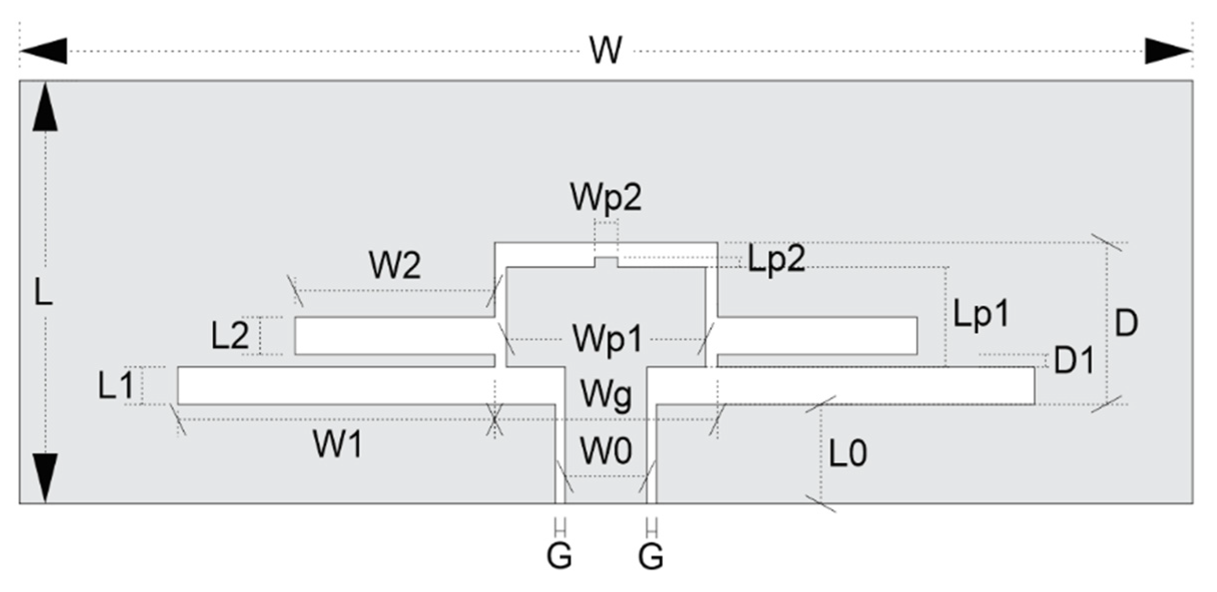
Through a parametric analysis in the HFSS simulator, the optimized antenna dimensions were obtained, and they are shown in Figure 2 and described in Table 2, respectively. The antenna feedline was calculated to obtain a coplanar waveguide (CPW) with a characteristic impedance of 50 ohms. The proposed transparent antenna is a capacitively coupled CPW-fed slot, dipole antenna with two pairs of protruded slot lines with different lengths, W1 and W2. The resonant frequencies correspond to the two different resonant paths. The two resonance frequencies for the design are 1.9 GHz and 5.9 GHz, which are used in LTE and 802.11p, respectively. Besides, in the parametric analysis, we made variations over the parameters W1, W2, and Wp1, to reach the desired frequency bands performing the matching impedance and observe their impact on the antenna design.
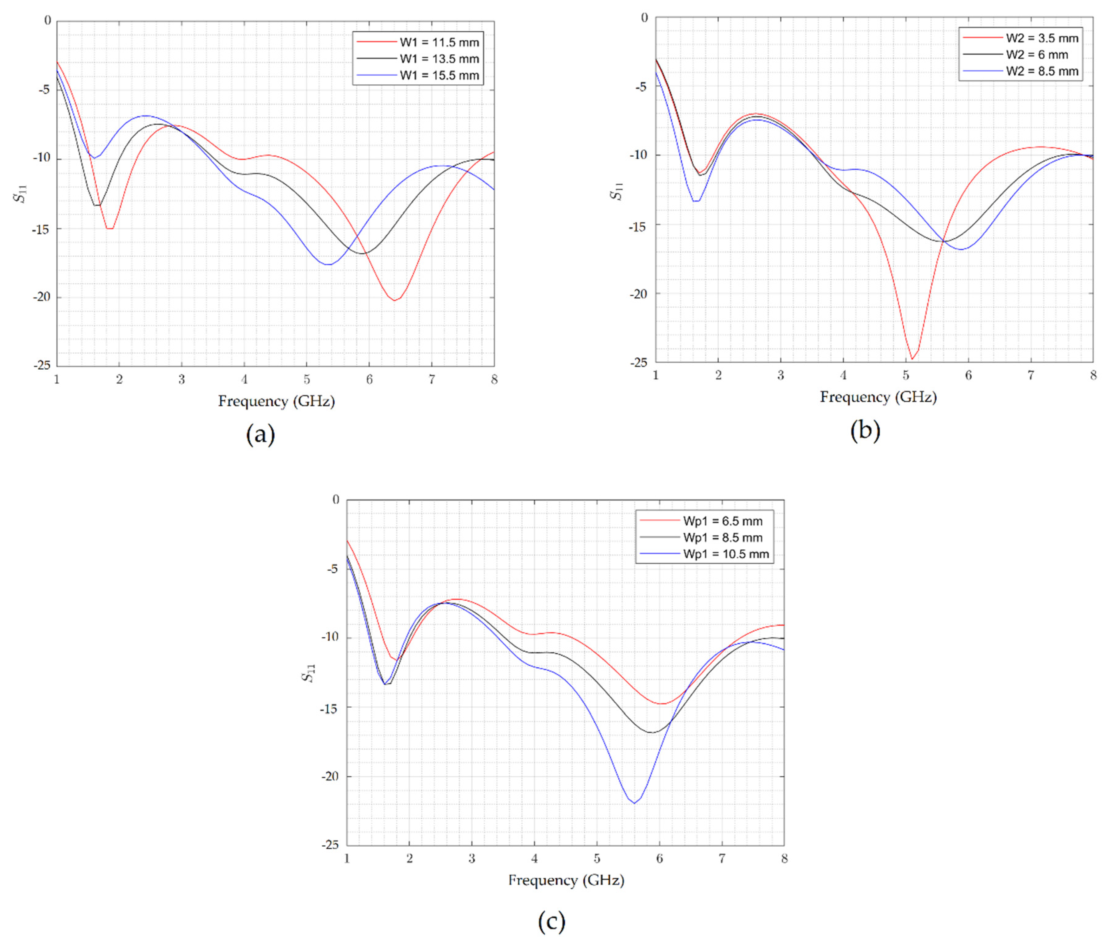
In [40], it is mentioned that the resonant frequencies are independently controlled by a common aperture and the three pairs of respective thin slots. However, in our design, the variation of the length W1 shift both frequencies, as shown in Figure 3a. Moreover, Figure 3b shows variations in the higher frequency due to change in the length W2, while the lower frequency is fixed. Similar behavior is observed in Figure 3c when varying the width of the central patch, the high frequency is mainly affected, whereas the lower band is minimally changed. The reason is attributable to the fact that lengths of W2 and Wp1 are closer to the shortest wavelength [41]. It is important to mention that in our simulations, the SMA connector was considered.

3. Results and Discussion

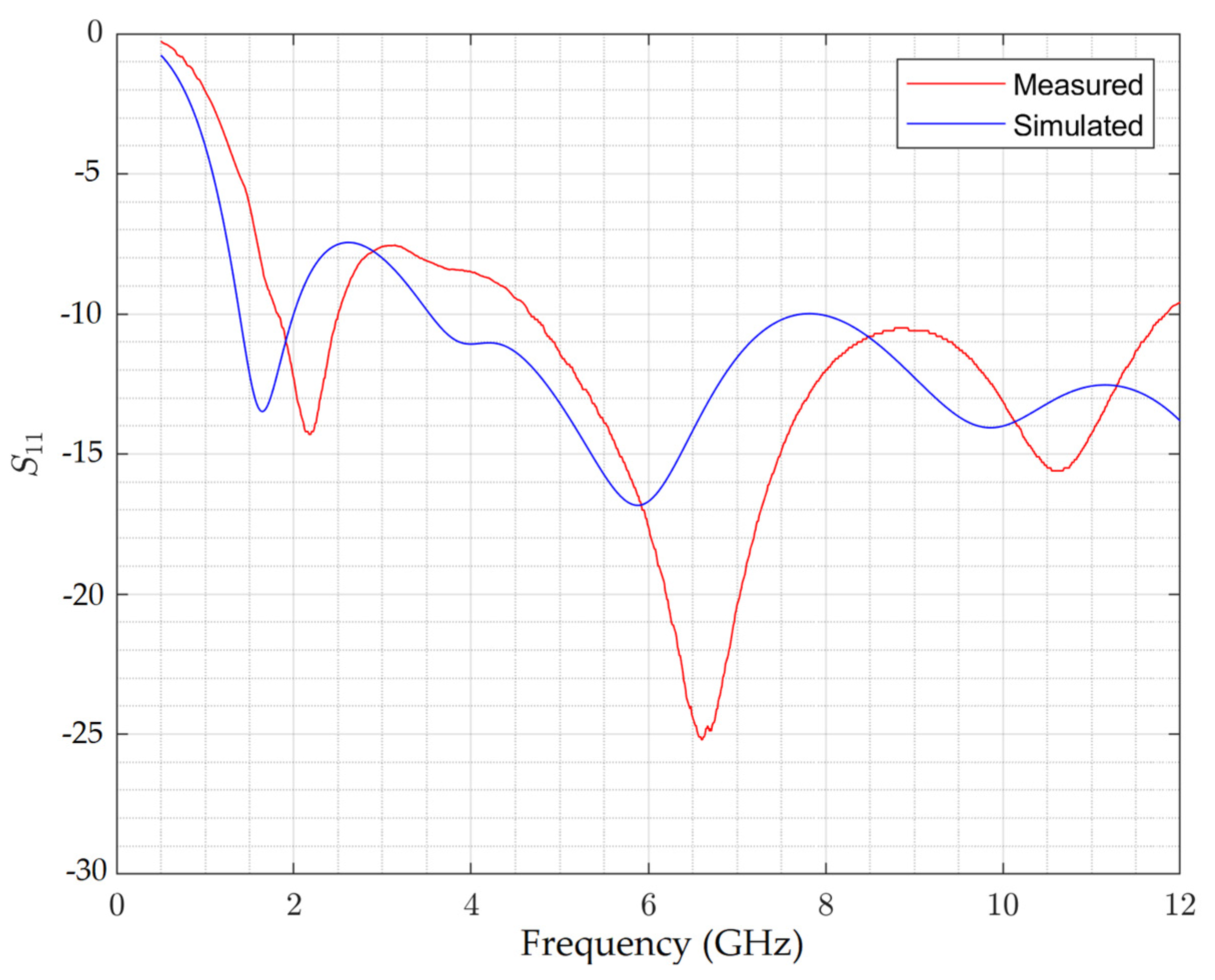
After obtaining the results through numerical simulation, the antenna was manufactured, and measurements of return loss, gain, and radiation diagrams were performed. The transparent antenna was fabricated by using a photolithography process. The transfer of the antenna geometry to the ITO-coated glass was made using a photosensitive film, which was exposed to UV light through a mask with the antenna geometry. Then the area exposed was removed to continue with the etching of the ITO films with a (1:1) solution of hydrochloric acid (HCL). This last process was done at 40 °C temperature for 2 min. Finally, we remove the photoresistant layer. Besides, an SMA connector was employed to connect the antenna; this connector was soldered to the transparent antenna using indium (In) solder spheres. The fabricated antenna placed onto the BUAP label is shown in Figure 4, where the transmittance of the ITO can be observed. The vector network analyzer (VectorStar, Anritsu) was used to measure the S11 from 0.5 GHz to 12 GHz. The simulated and measured return loss (S11) are shown and compared in Figure 5. The measured S11 at 5.9 GHz is −16.7 dB, which shows a good agreement with the simulated results.
Although a slightly detuned response is obtained from the measurement, related to fabrication flaws, each fractional bandwidth (FWB) remains, as can be seen in Table 3, showing the FBW for every band in simulation and measurement. The measured FBWs for S11 below −10 dB at the lower band is 31.34% (1.82 to 2.5 GHz), and at the upper band is 87.03% (4.66 to 11.84 GHz), which is large enough to cover the 5.9 GHz required frequency. Thus, experimental results fulfill the communication IEEE 802.11p standard for the required band.
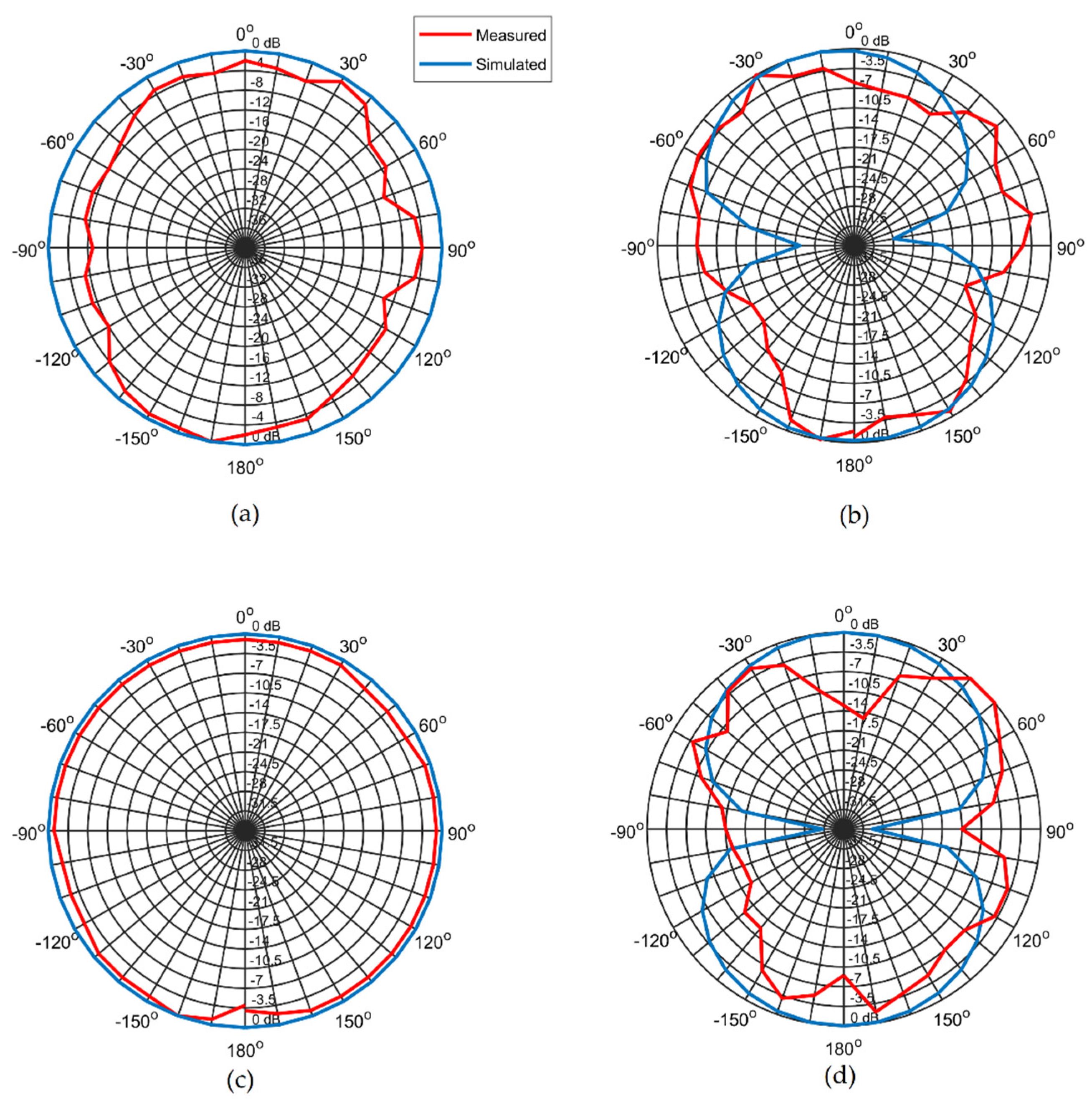
Figure 6 shows the simulated and measured 2-D radiation patterns of the proposed antenna at 2.1 and 5.9 GHz. At both frequencies, the H-plane radiation pattern presents omnidirectional behavior, whereas the E-plane radiation pattern is bidirectional. Moreover, to complete the characterization of the antenna, the peak gain of the antenna was simulated and measured at 2.1 and 5.9 GHz—Table 4 summarizes the obtained peak gains. The measured radiation patterns and peak gains are in concordance with the simulate results. Besides, the antenna efficiency at 2.1 and 5.9 GHz was simulated; the obtained values are 10% and 15%, respectively. These gain peaks and efficiency values are in agreement with those reported for other antennas that use ITO as a conductive film [43].
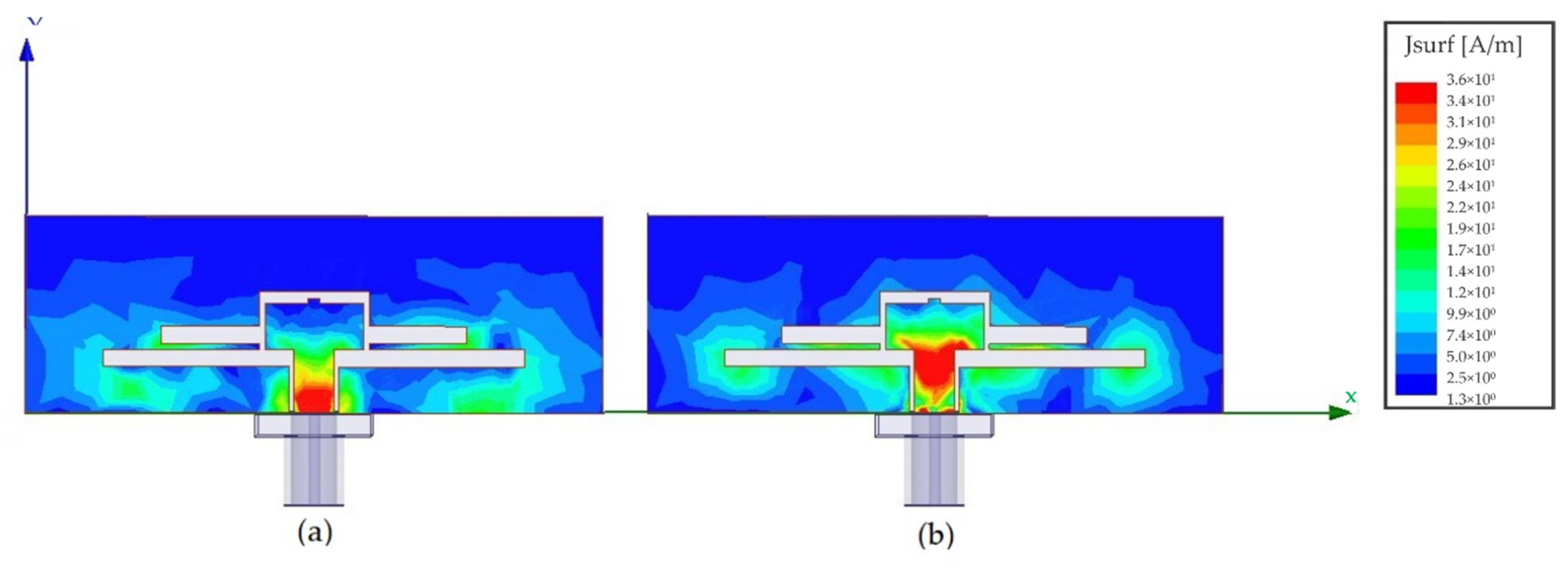
Furthermore, the current distribution for the transparent antenna was obtained by simulation at 2.1 and 5.9 GHz, and it is presented in Figure 7. From Figure 7a, it is observed that the distribution current at 2.1 GHz is more intense on the feedline and, at the bottom of the middle path. Another significant amount of current is around the geometry of the antenna. On the other hand, at 5.9 GHz, the current distribution is mainly on the feedline, and at the middle patch. However, there is a significant amount of current between the resonators and at the largest resonator edges, as shown in Figure 7b.
Finally, Table 5 presents a comparison of the proposed antenna with other transparent antennas. From the table, it can be noted that the antennas manufactured with ITO [22,23,24] do not report a fair agreement between the simulated and measured values of the reflection coefficient throughout the entire frequency range of the study, whereas in this work we can see a reasonable concordance between simulated and measured values. The frequency shift may be due to the manufacturing process and the variations in the permittivity of the substrate.

4. Conclusions

A CPW-fed fully transparent antenna for vehicular communication standards was designed, manufactured, and measured. The crossmatch technique was used for the impedance matching to achieve the target frequencies through parametric simulation. The antenna was designed and fabricated using commercial ITO-coated glass with a sheet resistance of 8 ohms/square. Opposite to other works that also use conductive films with a high sheet resistance, the experimental parameters obtained showed a behavior following the one simulated. Despite the frequency shift in the measured reflection coefficient, the fabricated antenna covers the range of 1.82–2.5 GHz at the lower band and 4.66–11.84 GHz at the upper band for 2.1 GHz and 5.9 GHz requirements, respectively. Those ranges comply with the IEEE 802.11p standard and LTE sub 6 GHz communication bands for vehicular communications applications. The proposed antenna achieves an omnidirectional radiation H-plane patterns. As expected, the peaks gain of the antenna, in the desired frequencies, were negative. Additionally, the proposed antenna presents low radiation efficiency under 15%. These behaviors are due to the sheet resistance of the ITO film, and it can be improved by increasing the thickness of the ITO film, but it would reduce the transparency of the antenna.

Author Contributions

Conceptualization, J.I.T.-F., R.T.-M., J.M.M.-P., M.A.V.-A., E.I.T.-F., M.L.-L., and E.C.-B.; methodology, J.I.T.-F., R.T.-M., and E.C.-B.; software, J.I.T.-F., R.T.-M., M.L.-L., and E.C.-B.; validation, J.I.T.-F., R.T.-M., and E.C.-B.; formal analysis, J.I.T.-F., R.T.-M., J.M.M.-P., E.I.T.-F., M.L.-L., and E.C.-B.; investigation, J.I.T.-F., R.T.-M., and E.C.-B.; measurements, J.I.T.-F., R.T.-M., and E.C.-B.; data curation, J.I.T.-F., R.T.-M., and E.C.-B.; writing—original draft preparation, J.I.T.-F., R.T.-M., and E.C.-B.; writing—review and editing, J.I.T.-F., R.T.-M., J.M.M.-P., E.I.T.-F., M.L.-L., and E.C.-B.; supervision, R.T.-M. and J.M.M.-P.; project administration, J.I.T.-F., and R.T.-M.; All authors have read and agreed to the published version of the manuscript.

Funding

This research received no external funding.

Acknowledgments

With thanks to the laboratory of characterization of systems based on microwaves at FCE-BUAP where all experimental characterizations were carried out. J.

Conflicts of Interest

The authors declare no conflict of interest.

References

  1. Koga, Y.; Kai, M. A transparent double folded loop antenna for IoT applications. In Proceedings of the 2018 IEEE-APS Topical Conference on Antennas and Propagation in Wireless Communications (APWC), Cartagena des Indias, Colombia, 10–14 September 2018; pp. 762–765. [Google Scholar]
  2. Jain, B.; Brar, G.; Malhotra, J.; Rani, S. A novel approach for smart cities in convergence to wireless sensor networks. Sustain. Cities Soc. 2017, 35, 440–448. [Google Scholar] [CrossRef]
  3. Kirimtat, A.; Krejcar, O.; Kertesz, A.; Tasgetiren, M.F. Future trends and current state of smart city concepts: A survey. IEEE Access 2020, 8, 86448–86467. [Google Scholar] [CrossRef]
  4. Alavi, A.H.; Jiao, P.; Buttlar, W.G.; Lajnef, N. Internet of things-enabled smart cities: State-of-the-art and future trends. Measurement 2018, 129, 589–606. [Google Scholar] [CrossRef]
  5. Bibri, S.E.; Krogstie, J. Smart sustainable cities of the future: An extensive interdisciplinary literature review. Sustain. Cities Soc. 2017, 31, 183–212. [Google Scholar] [CrossRef]
  6. Wang, J.; Jiang, C.; Zhang, K.; Quek, T.Q.S.; Ren, Y.; Hanzo, L. Vehicular sensing networks in a smart city: Principles, technologies and applications. IEEE Wirel. Commun. 2018, 25, 122–132. [Google Scholar] [CrossRef] [Green Version]
  7. Matyakubov, M.; Rustamova, O. Development of smart city model: Smart bus system. In Proceedings of the 2019 International Conference on Information Science and Communications Technologies (ICISCT), Tashkent, Uzbekistan, 9–10 March 2019; pp. 1–5. [Google Scholar]
  8. Yang, L.; Mo, T.; Li, H. Research on V2V communication based on peer to peer network. In Proceedings of the 2018 International Conference on Intelligent Autonomous Systems (ICoIAS), Singapore, 1–3 March 2018; pp. 105–110. [Google Scholar]
  9. Alami, A.J.; El-Sayed, K.; Al-Horr, A.; Artail, H.; Guo, J. Improving the Car GPS accuracy using V2V and V2I communications. In Proceedings of the 2018 IEEE International Multidisciplinary Conference on Engineering Technology (IMCET), Beirut, Lebanon, 14–16 November 2018; pp. 1–6. [Google Scholar]
  10. Franzo, S.; Latilla, V.M.; Longo, M.; Bracco, S. Towards the new concept of smart roads: Regulatory framework and emerging projects overview. In Proceedings of the 2018 International Conference of Electrical and Electronic Technologies for Automotive, Milan, Italy, 9–11 July 2018; pp. 1–6. [Google Scholar]
  11. Jiang, D.; Delgrossi, L. Towards an international standard for wireless access in vehicular environments. In Proceedings of the VTC Spring 2008—IEEE Vehicular Technology Conference, Singapore, 11–14 May 2008; pp. 2036–2040. [Google Scholar]
  12. Roque-Cilia, S.; Tamariz-Flores, E.I.; Torrealba-Meléndez, R.; Covarrubias-Rosales, D.H. Transport tracking through communication in WDSN for smart cities. Measurement 2019, 139, 205–212. [Google Scholar] [CrossRef]
  13. IEEE Standard for Information Technology—Local and Metropolitan Area Networks—Specific Requirements—Part 11: Wireless LAN Medium Access Control (MAC) and Physical Layer (PHY) Specifications Amendment 6: Wireless Access in Vehicular Environments; IEEE: New York, NY, USA, 2010.
  14. Ucar, S.; Ergen, S.C.; Ozkasap, O. Multihop-cluster-based IEEE 802.11p and LTE hybrid architecture for VANET safety message dissemination. IEEE Trans. Veh. Technol. 2016, 65, 2621–2636. [Google Scholar] [CrossRef] [Green Version]
  15. Arena, F.; Pau, G.; Severino, A. A Review on IEEE 802.11p for intelligent transportation systems. J. Sens. Actuator Netw. 2020, 9, 22. [Google Scholar] [CrossRef]
  16. Choi, J.-Y.; Jo, H.-S.; Mun, C.; Yook, J.-G. Preamble-based adaptive channel estimation for IEEE 802.11p. Sensors 2019, 19, 2971. [Google Scholar] [CrossRef] [Green Version]
  17. Klapez, M.; Grazia, C.A.; Casoni, M. Minimization of IEEE 802.11p packet collision interference through transmission time shifting. J. Sens. Actuator Netw. 2020, 9, 17. [Google Scholar] [CrossRef] [Green Version]
  18. Xie, Y.; Ho, I.W.; Magsino, E.R. The modeling and cross-layer optimization of 802.11p VANET Unicast. IEEE Access 2018, 6, 171–186. [Google Scholar] [CrossRef]
  19. Syfullah, M.; Lim, J.M.-Y. Data broadcasting on Cloud-VANET for IEEE 802.11p and LTE hybrid VANET architectures. In Proceedings of the 3rd International Conference on Computational Intelligence & Communication Technology (CICT), Ghaziabad, India, 10–13 February 2017; pp. 1–6. [Google Scholar]
  20. Arora, A.; Mehra, A.; Mishra, K.K. Vehicle to vehicle (V2V) VANET based analysis on waiting time and performance in LTE network. In Proceedings of the 3rd International Conference on Trends in Electronics and Informatics (ICOEI), Tirunelveli, India, 23–25 April 2019; pp. 482–489. [Google Scholar]
  21. IEEE Standard for Definitions of Terms for Antennas; IEEE: New York, NY, USA, 1973.
  22. Duraj, D.; Rzymowski, M.; Nyka, K.; Kulas, L. ESPAR Antenna for V2X applications in 802.11p frequency band. In Proceedings of the 13th European Conference on Antennas and Propagation (EuCAP), Krakow, Poland, 31 March–5 April 2019; pp. 1–4. [Google Scholar]
  23. Condo Neira, E.; Carlsson, J.; Karlsson, K.; Ström, E.G. Combined LTE and IEEE 802.11p antenna for vehicular applications. In Proceedings of the 9th European Conference on Antennas and Propagation (EuCAP), Lisbon, Portugal, 12–17 April 2015; pp. 1–5. [Google Scholar]
  24. Madhav, B.; Anilkumar, T.; Kotamraju, K. Transparent and conformal wheel-shaped fractal antenna for vehicular communication applications. AEU Int. J. Electron. Commun. 2018, 91, 1–10. [Google Scholar] [CrossRef]
  25. Green, R.B.; Toporkov, M.; Ullah, M.D.B.; Avrutin, V.; Ozgur, U.; Morkoc, H.; Topsakal, E. An alternative material for transparent antennas for commercial and medical applications. Microw. Opt. Technol. Lett. 2017, 59, 773–777. [Google Scholar] [CrossRef]
  26. Lee, S.; Choo, M.; Jung, S.; Hong, W. Optically transparent nano-patterned antennas: A review and future directions. Appl. Sci. 2018, 8, 901. [Google Scholar] [CrossRef] [Green Version]
  27. Eltresy, N.A.; Elsheakh, D.N.; Abdallah, E.A.; Elhennawy, H.M. RF energy harvesting using transparent antenna for IoT application. In Proceedings of the 2019 International Conference on Innovative Trends in Computer Engineering (ITCE), Aswan, Egypt, 2–4 February 2019; pp. 287–291. [Google Scholar]
  28. Cai, L. An on-glass optically transparent monopole antenna with ultrawide bandwidth for solar energy harvesting. Electronics 2019, 8, 916. [Google Scholar] [CrossRef] [Green Version]
  29. Hakimi, S.; Rahim, S.K.A.; Abedian, M.; Noghabaei, S.M.; Khalily, M. CPW-fed transparent antenna for extended ultrawideband applications. IEEE Antennas Wirel. Propag. Lett. 2014, 13, 1251–1254. [Google Scholar] [CrossRef]
  30. Júnior, P.F.D.S.; Freire, R.C.S.; Serres, A.; Catunda, S.Y.; Silva, P.H.D.F. Bioinspired transparent antenna for WLAN application in 5 GHz. Microw. Opt. Technol. Lett. 2017, 59, 2879–2884. [Google Scholar] [CrossRef]
  31. Hong, S.; Kang, S.H.; Kim, Y.; Jung, C.W. Transparent and flexible antenna for wearable glasses applications. IEEE Trans. Antennas Propag. 2016, 64, 2797–2804. [Google Scholar] [CrossRef]
  32. Hautcoeur, J.; Colombel, F.; Castel, X.; Himdi, M.; Cruz, E.M. Radiofrequency performances of transparent ultra-wideband antennas. Prog. Electromagn. Res. C 2011, 22, 259–271. [Google Scholar] [CrossRef] [Green Version]
  33. Martin, A.; Castel, X.; Lafond, O.; Himdi, M. Optically transparent frequency-agile antenna for X-band applications. Electron. Lett. 2015, 51, 1231–1233. [Google Scholar] [CrossRef]
  34. Martin, A.; Castel, X.; Himdi, M.; Lafond, O. Mesh parameters influence on transparent and active antennas performance at microwaves. AIP Adv. 2017, 7, 085120. [Google Scholar] [CrossRef]
  35. Martin, A.; Lafond, O.; Himdi, M.; Castel, X. Improvement of 60 GHz transparent patch antenna array performance through specific double-sided micrometric mesh metal technology. IEEE Access 2019, 7, 2256–2262. [Google Scholar] [CrossRef]
  36. Desai, A.; Upadhyaya, T.; Patel, J.; Patel, R.; Palandoken, M. Flexible CPW fed transparent antenna for WLAN and sub-6 GHz 5G applications. Microw. Opt. Technol. Lett. 2020, 62, 2090–2103. [Google Scholar] [CrossRef]
  37. Desai, A.; Upadhyaya, T.; Palandoken, M.; Patel, J.; Patel, R. Transparent conductive oxide-based multiband CPW fed antenna. Wirel. Pers. Commun. 2020, 113, 961–975. [Google Scholar] [CrossRef]
  38. Kashanianfard, M.; Sarabandi, K. Vehicular optically transparent UHF antenna for terrestrial communication. IEEE Trans. Antennas Propag. 2017, 65, 3942–3949. [Google Scholar] [CrossRef]
  39. Lee, J.; Lee, H.; Kim, D.; Jung, W. Transparent dual-band monopole antenna using a μ-metal mesh on the rear glass of an automobile for frequency modulation/digital media broadcasting service receiving. Microw. Opt. Technol. Lett. 2019, 61, 503–508. [Google Scholar] [CrossRef]
  40. Liu, T.-W.; Tu, W.-H. CPW-fed tri-band slot antenna with impedance matching stub. In Proceedings of the 2016 IEEE/ACES International Conference on Wireless Information Technology and Systems (ICWITS) and Applied Computational Electromagnetics (ACES), Honolulu, HI, USA, 13–17 March 2016; pp. 1–2. [Google Scholar]
  41. Chen, S.-Y.; Chen, Y.-C.; Hsu, P. CPW-fed aperture-coupled slot dipole antenna for tri-band operation. IEEE Antennas Wirel. Propag. Lett. 2008, 7, 535–537. [Google Scholar] [CrossRef]
  42. Smits, F.M. Measurement of sheet resistivities with the four-point probe. Bell Syst. Tech. J. 1958, 37, 711–718. [Google Scholar] [CrossRef]
  43. Haraty, M.R.; Naser-Moghadasi, M.; Lotfi-Neyestanak, A.A.; Nikfarjam, A. Improving the efficiency of transparent antenna using gold nano Layer deposition. IEEE Antennas Wirel. Propag. Lett. 2015, 4–7. [Google Scholar] [CrossRef]
Figure 1. Schematic positions on indium-tin oxide (ITO) film placed on a glass slide for sheet resistance (Rs)/square measurement.
Applsci 10 06001 g001
Figure 2. Antenna configuration with dimensions.
Applsci 10 06001 g002
Figure 3. Simulated reflection coefficient of the ITO antenna for three parameters variations: (a) W1; (b) W2; (c) Wp1.
Applsci 10 06001 g003
Figure 4. Manufactured antenna photography.
Applsci 10 06001 g004
Figure 5. Comparison of simulated and measured return loss parameters.
Applsci 10 06001 g005
Figure 6. Simulated and measured radiation patterns: (a) H-plane patterns at 5.9 GHz; (b) E-plane patterns at 5.9 GHz; (c) H-plane patterns at 2.1 GHz; (d) E-plane patterns at 2.1 GHz.
Applsci 10 06001 g006
Figure 7. Simulated distribution current at (a) 2.1 GHz and (b) 5.9 GHz.
Applsci 10 06001 g007
Table 1. Rs/Square Measurements Obtained on ITO Film.
PositionResistance (Ω)
17.831
27.909
37.970
48.008
58.035
67.997
77.914
87.954
97.914
107.900
117.922
127.958
137.950
Average7.943
Table 2. Dimensions of the Proposed Antenna.
ParameterSize (mm)ParameterSize (mm)
W50L17
Wg9.5Lp14
Wp18.5Lp20.4
Wp21L04
W03.5L11.5
W113.5L21.5
W28.5D6.5
G0.4D10.5
Table 3. Simulated (S) and Measured (M) Fractional Bandwidth Comparison. FBW: Fractional Bandwidth.
frangeFBW
S1.39–1.9936.36%
M1.82–2.531.34%
S3.54–7.7571.35%
M4.66–11.8487.03%
Table 4. Simulated (S) and Measured (M) Peak Gain.
2.1 GHz5.9 GHz
S−0.167 dB−2.12 dB
M−0.145 dB−3.9 dB
Table 5. Comparative Analysis with Other Transparent Antennas.
Reference.Frequencies (GHz)S11 Min Level (dB)Substrate//Conductive FilmDimensions (mm)Match between M and S of S11 *
[25]2.19–2.58−13.97Sapphire//GZO60 × 10 × 0.375No
[29]2–6−25Glass//ITO25 × 25 × 1.1No
[30]1–7<−15Glass//ITO50 × 50 × 1.1No reported
[32]4.5–7−25Acetate//ITO50 × 51 × 0.28No
[33]2.4–2.65−15C58//IZTO/Ag/IZTO23.4 × 2Yes
[38]3.89–5.97−24PET//AgHT-858 × 78 × 0.9Yes
This work1.8–2.5/4.66–11.84−25Glass//ITO50 × 17 × 1.1Yes
* (M) Measured, (S) Simulated.